

GPI MR 5-30 Series, MR 5-30N Series Owner's Manual
General Information ....................2
Installation ..................................3
Operation ....................................3
Calibration ..................................4
Maintenance ...............................5
Troubleshooting ..........................6
Specications .............................7
Illustrated Parts List ....................8
TABLE OF CONTENTS
SAVE THESE INSTRUCTIONS
MR 5-30 or MR 5-30N Series
Fuel Meter
Owner’s Manual
To the owner…
Congratulations on receiving your GPI
MR 5-30 Meter . W e are pleased to provide
you with a meter designed to give you
maximum reliability and efciency.
Our business is the design, manufacture and
marketing of liquid handling, agricultural and
recreational products. We succeed because
we provide customers with innovative,
reliable, safe, timely and competitivelypriced products. We pride ourselves in
conducting our business with integrity and
professionalism.
We are proud to provide you with a quality
product and the support you need to obtain
years of safe, dependable service.
Great Plains Industries, Inc. is a member
of the Petroleum Equipment Institute.
Victor Lukic, President
Great Plains Industries, Inc
2
GENERAL INFORMATION
The purpose of this manual is to
assist you in installing, operating
and maintaining your mechanical
fuel meter. Please take a few moments to read these instructions
before installing and operating your
fuel meter.
SAFETY INSTRUCTIONS
The following safety alert symbols
are used in this manual.
DANGER
DANGER indicates a hazardous
situation which, if not avoided, will
result in death or serious injury.
WARNING
WARNING indicates a hazardous
situation which, if not avoided, could
result in death or serious injury.
CAUTION
CAUTION indicates a hazardous
situation which, if not avoided, may
result in minor or moderate injury.
It is your responsibility to:
• know and follow applicable
national, state and local safety
codes pertaining to installing and
operating electrical equipment for
use with ammable liquids.
• know and follow all safety precau-
tions when handling petroleum
fuels
• ensure that all equipment operators have access to adequate
instructions concerning safe
operation and maintenance.
1. This meter is designed for use
only with thin viscosity petroleum fuels such as gasoline,
gasoline/ethanol blends at levels
designated as "gasohol" (E10
maximum), diesel and kerosene.
2. Do not use this equipment for
dispensing any uids other than
those for which it was designed.
T o do so may damage the meter
and will void the warranty.
3.
DANGER
Observe precau-
tions against re or explosion
when dispensing fuel. Do not
operate the meter in the presence
of any source of ignition including
running or hot engines, lighted
cigarettes, or gas or electric
heaters.
4.
WARNING
Any components
such as hose, nozzle, or pump
added to your meter must be
statically grounded and approved
for use with petroleum fuels.
5.
WARNING
Avoid prolonged
skin contact with petroleum fuels.
Use protective goggles, gloves,
and aprons in case of accidental
splashing or spillage. Change
saturated clothing and wash skin
contact areas promptly with soap
and water.
The MR 5-30 Mechanical Fuel
Meter is designed for the eld measurement of thin viscosity petroleum
fuels only and intended for use with
pump systems in the 5 to 30 GPM
or 19 to 114 LPM ow range (not
intended for gravity ow systems).
Using mechanical gears, these
meters translate ow data from a
nutating disk into calibrated units
which are indicated on the face
of the meter. This meter is factory
calibrated for diesel fuel. Field calibration feature is available for other
uids, see Calibration section.
3
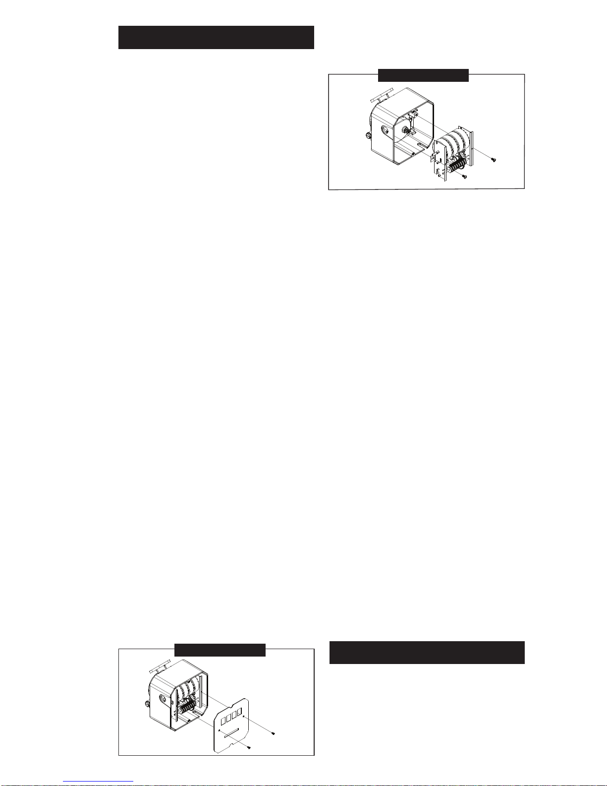
FIGURE 1
INSTALLATION
Before installing your meter, review
the safety instructions given above.
Examine your meter to make sure
there are no visible signs of shipment
damage. Plan your meter installation
by reviewing the following procedures.
Your system must be mounted on a
vented tank. If the tank is unvented,
your local dealer or distributor can
supply a pressure cap.
If the meter is located in a rigid piping
system where the uid is trapped
(for example, by gravity, valves or
nozzles) thermal expansion of the
uid can create pressure spikes that
can damage a meter.
Install a thermal relief valve or oth-
erwise allow for thermal expansion
of the uid.
Prior to installation, determine the
tting angle desired and whether
horizontal or vertical orientation is
required.
Rotate Fittings
To rotate inlet and/or outlet ttings,
remove the two nuts and bolts that
secure each tting. Rotate the tting
to the desired orientation. Make sure
the O-ring is fully seated. Tighten the
nuts and bolts snugly.
C
hange Orientation
1. Pull the knob to remove from unit.
Remove screws that hold bezel
in place and set aside.
2. Remove the two screws that hold
the faceplate in place and remove
faceplate. (Figure 1)
FIGURE 2
3. Remove two screws to release
the counter assembly . (Figure 2)
4. Remove the bevel gear from the
center of the coverplate. Remove
the eight pairs of nuts and bolts
that hold the coverplate assembly
in place.
5. Now you can rotate the coverplate
to the desired orientation. Reassemble in reverse order , making
sure the O-ring is fully seated.
Torque eight nuts and bolts to
60 - 72 in-lb.
Meter Installation
1. Remove protective plugs from
the meter inlet and outlet ports.
2. Wrap threaded male connections
with thread tape or use a pipe
sealant compound compatible
with petroleum fuels. We recommend thread sealant at the inlet
tting in horizontal orientation.
3. Install the meter on the pump using an appropriately sized nipple.
The meter’s ow path is marked on
the housing exterior with an arrow
pointing toward the outlet port.
4. Install other system components
on the meter and tighten snugly .
OPERATION
AL WA YS FOLLOW SAFETY PRECAUTIONS WHEN OPERATING
THIS EQUIPMENT. REVIEW THE
SAFETY INSTRUCTIONS. Before
each use, visually check the meter
to ensure it is securely connected to
 Loading...