

Page 1
1
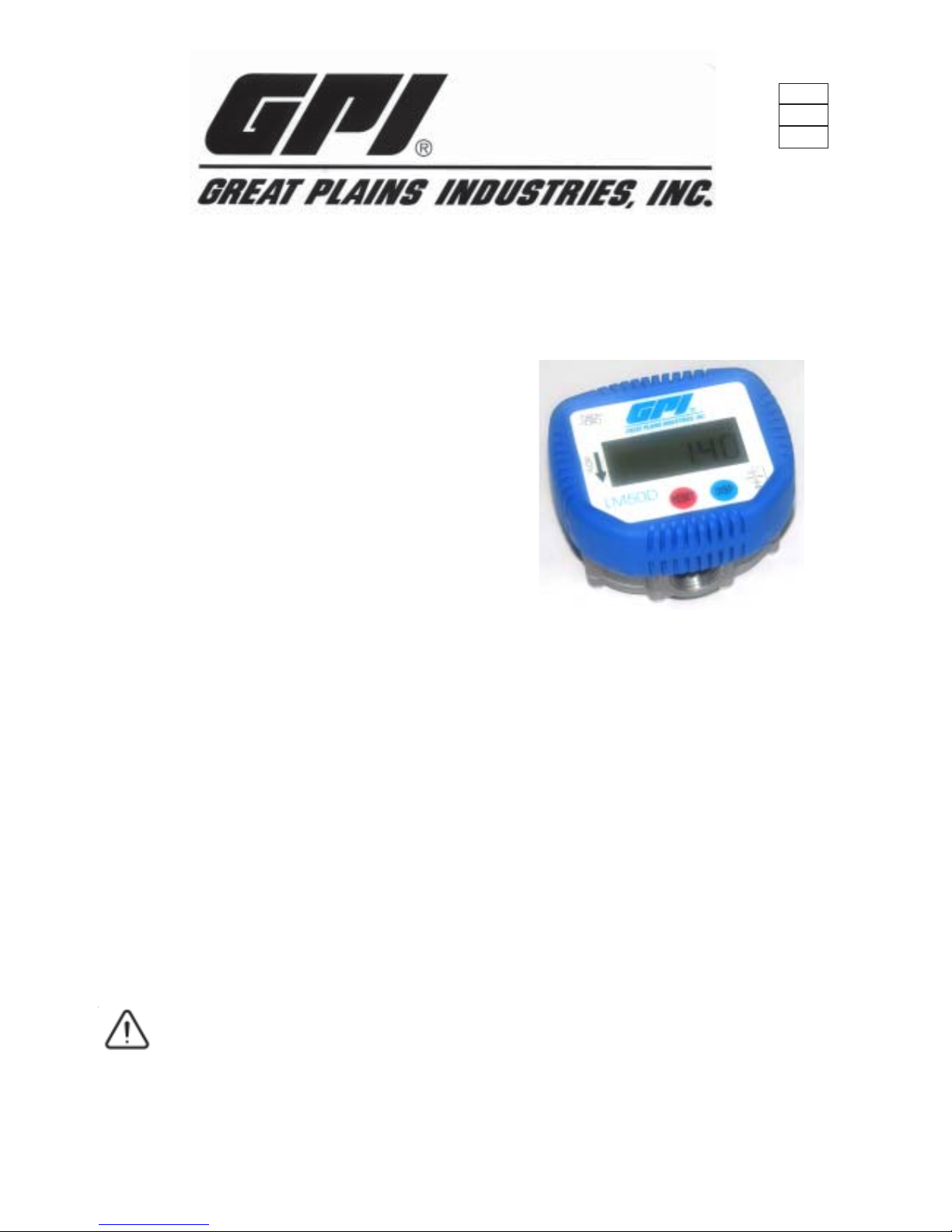
LM50DB / LM50DN (ELECTRONIC)
INSTRUCTION MANUAL
This meter is designed for in line use with Engine Oil & A TF
up to a maximum viscosity of SAE 140, Diesel & Water Glycol mixtures with a maximum water content of less than 50%.
Please read and retain this instruction manual to
assist you in the operation and maintenance of this
quality product.
GENERAL INFORMA TION
This manual assists you in operating and maintaining your
new positive displacement flowmeter. The information
contained will help you ensure many years of dependable
performance and trouble free operation.
Please take a few moments to read through this manual before
installing and operating your new meter. If you experience
problems with this product, refer to the Maintenance and
Trouble Shooting sections of this manual. If you require
further assistance please contact your local GPI
Distributor.
IMPORTANT INFORMA TION
The GPI quality Positive displacement flowmeter has
incorporated the oval rotor principal into its design. This has
proven to be a highly reliable and highly
accurate method of measuring flow, pr oviding exceptional
repeatability and high accuracy .
GPI recommends, that if you are using your meter as an inline application you should install a filter
before the inlet of the meter. Contact your local GPI distributor
for further details.
INSTALLATION
2) Do not over tighten connections.
0002
OPERATION
LM50DB or LM50DN ELECTRONIC REGISTER
DISPLA Y BUTT ON
Each press of the DISP button will allow you to scroll through
the meter options
Resetable Batch T otal
Resetable Accumulative T otal
Non Resetable Accumulative T otal
Flowrate
RESET BUTTON
The RESET button allows you to reset the Batch T otal or the
Resettable Acumulative T otal to zero.
To reset either the Batch total or Resetable Acumulative total.
Press the DISP button to scroll to either the Batch or Resetable
total . When the required total is displayed. Press reset to zero
the totalizer.
FLOWRATE
This display option shows the flowrate of the fluid
passing through the meter.
IM083
0106
POSITIVE DISPLACEMENT FLOWMETERS
Page 2
2
CAUTION
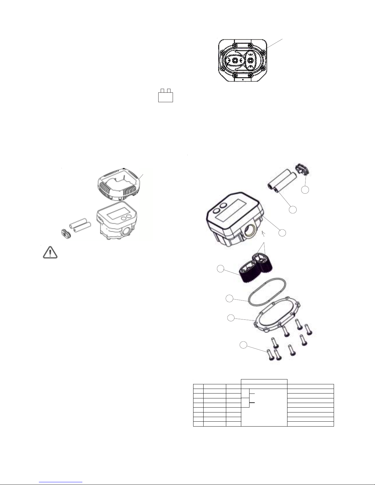
METER DISASSEMBLY
P A RTS DIAGRAM
Ensure the fluid supply to the meter is disconnected and
the line pressure is released befor e disassembly.
METER REASSEMBLY
1) Replace both rotors (4) so as they are at 90O to each other.
(see fig 2). Check the rotor rotation by turning either of the
rotors. If the rotors are not in mesh correctly or do not
rotate freely remove one of the rotors and replace it
correctly at 900 to the other rotor. Re-check the operation of
the rotors.
5) Test the meter by turning the rotors with a finger or by
applying low air pressure (No more than a good breath)
to the inlet port of the meter. This will confirm the meter
is operating correctly .
1
2
5
6
7
4
3
PARTS LIST
BA TTERY REPLACEMENT
1) Remove the plastic protector shroud from the meter
body. (fig 1)
3) Replace the 2 x (AAA) Alkaline batteries. (Refer to the
front of the meter for correct battery orientation).
Note: Only use Alkaline batteries.
If NO flow goes through the meter for 60 seconds the display
will go into sleep mode (Blank). The display will
automatically wake if the buttons are pressed or flow occurrs.
SLEEP MODE
Note: The electronic computer module is non-repairable. The
meter will need to be replaced if found to be damaged or faulty.
1) Remove the 8 x philips head screws (1) from the meter
cover.
2) Remove the meter cover (2) and o’ring (3).
3) Remove both rotors (4).
4) Clean and inspect all parts. Replace any suspect, worn or
damaged components.
NOTE: Ensure the rotor with the magnets is assembled on
the same side as the batteries. The magnets in the rotor must
face towards the electronic display .
The Rotor with Magnets
( fig 2)
(fig 1)
magnets
Note: Replace the batteries as soon as the battery
indicator on the LCD is displayed
+
-
2) Remove the battery cover.
4) Replace the battery cover and re-fit the plastic shroud.
All data will be saved when the batteries are removed.
2) Lightly grease the o’ring (3) and place it on the meter body.
3) Clean the meter cover plate (2) and place it on the body.
T ake care not to damage the o’ring (3).
4) Install the 8 screws (1) and tighten in a diagonal pattern to
1nm (0.73 ft.lb). Visual check the cap has been pulled down
evenly.
Protector Shroud
(fig 3)
ORDER FOR REPLACEMENT
ITEM PART NO No. of f PART/ SET DESCRIPTION
1 N65 8 LM50K02 SCREW SET
2 IM011 1 METER COV ER PLATE SET
3 BS035 1 LM50K01 O'RING SEAL
4IM020 2 ROTOR SET
5 1 N/A METER BODY
6 2 N/A BATTERY SET
7 1 N/A BATTERY COVER SET
8 IM070-BLUE 1 LM50K03 PROTECTOR SHROUD SET
Page 3

3
ELECTRONIC MODULE
PROGRAMING DETAILS
c) To access the programs and settings, hold down the RESET button for 5 seconds
d) T o scroll through the setting options press theDISP button.
The electronic module has been set up as follows:-
totL 2
rAtE 3
diSP 4
CALI 5
CONF 6
dIA 7
2. TOTALS
3. FLOWRATE
4. DISPLAY
5. CALIBRATION
6. CONFIGURATION
7. DIAGNOSTICS
NOTE: Details for changing individual options .
For example to change the units setting on the batch total turn to item 2 - 21
21 change batch total (units)
23 change resetable accumulative total (units)
24 change resetable accumulative total (decimal point)
25 change non-resetable accumulative total (units)
26 change non-reset accumulative total (decimal point)
22 change batch total (decimal point)
27 change “K” factor
31 change flowrate (units)
32 change flowrate (decimal point)
33 change flowrate (time base setting)
34 set the amount of signal pulses to calculate flowrate
35 set minimum flow rate
41 set sleep mode
43 set sleep time
42 change display (wake up default setting )
51 calibration adjustment
6 configuration details
71 diagnostic mode
a) Ensure the meter is awake before trying to enter the programming mode.
b) If the meter goes into sleep mode during programming, it will automatically
return to operating mode.
totL 2
Note: As the decimal point does not float we recommend that a maximum of 2 decimal
places be used, see below for details.
Page 4

4
e) Press and hold down RESET until “program” disappears
to accept setting.
2. TOTALS SETTINGS
totL2
a) Press and hold down RESET for 5 seconds until “totL2”
appears.
21 BATCH TOTAL = unit 21 (set units)
c) Press and hold down RESET for 2 seconds ( program will
appear)
d) Press RESET to scroll through the settings (ltr , gal, qrt) to
the desired units
b) Press RESET “ unit 21” will appear.
22 BA TCH T OTAL = dEC 22 (set decimal point)
b) Press RESET twice “ dEC 22” will appear.
c) Press and hold down RESET for 2 seconds ( program will
appear)
d) Press RESET to set the decimal point to 1st, 2nd, 3rd or
no decimal place. (e.g 11111.1 = 1 decimal place)
23 RESETABLE ACCUM T OTAL = unit 23 (set units)
b) Press RESET 3 times “ unit 23” will appear.
c) Press and hold down RESET for 2 seconds ( program will
appear)
d) Press RESET to scroll through the settings ( ltr, gal, qrt )
to the desired units
24 RESETABLE ACCUM T OTAL = dEC 24
( set decimal point )
b) Press RESET 4 times “ dEC 24” will appear.
c) Press and hold down RESET for 2 seconds ( program will
appear)
d) Press RESET to set the decimal point to 1st, 2nd, 3rd or
no decimal place (e.g. 11111.1 = 1 decimal place).
25 NON-RESET ACCUM TOTAL = unit 25 (set units)
b) Press RESET 5 times “ unit 25” will appear .
c) Press and hold down RESET for 2 seconds ( program will
appear)
d) Press RESET to scroll through the settings (ltr, gal, qrt) to
the desired units.
26 NON-RESET ACCUM TOT AL = dEC 26
(set decimal point)
b) Press RESET 6 times “ dEC 26” will appear.
c) Press and hold down RESET for 2 seconds ( program will
appear)
d) Press RESET to set the decimal point to 1st, 2nd, 3rd or
no decimal place (e.g. 11111.1 = 1 decimal place).
27 “K” FACTOR = kFac 27
(normal setting is 112.00 pulses)
b) Press RESET 7 times “ kFac 27” will appear.
c) Press and hold down RESET for 2 seconds ( program will
appear)
T o change the ‘K’ factor , press RESET ( digit will flash),
to change digit press RESET.
Press DISP to scroll to the next number. Press RESET
to change the value
To change the decimal point, press DISP until it is
in the required position. Press RESET to set the decimal
point.
d)
e) Press and hold down RESET until “program” disappears
to accept setting.
e) Press and hold down RESET until “program” disappears
to accept setting.
e) Press and hold down RESET until “program” disappears
to accept setting.
e) Press and hold down RESET until “program” disappears
to accept setting.
e) Press and hold down RESET until “program” disappears
to accept setting.
e) Press and hold down RESET until “program” disappears
to accept setting.
f) Press RESET for five seconds to return the meter to the
operating mode.
f) Press RESET for five seconds to return the meter to the
operating mode.
f) Press RESET for five seconds to return the meter to the
operating mode.
f) Press RESET for five seconds to return the meter to the
operating mode.
f) Press RESET for five seconds to return the meter to the
operating mode.
f) Press “RESET” for five seconds to return the meter to the
operating mode.
f) Press RESET for five seconds to return the meter to the
operating mode.
a) Press and hold down RESET for 5 seconds until “totL2”
appears.
a) Press and hold down RESET for 5 seconds until “totL2”
appears.
a) Press and hold down RESET for 5 seconds until “totL2”
appears.
a) Press and hold down RESET for 5 seconds until “totL2”
appears.
a) Press and hold down RESET for 5 seconds until “totL2”
appears.
a) Press and hold down RESET for 5 seconds until “totL2”
appears.
Page 5

34 NUMBER OF PULSES = nuM 34
(Number of pulses used to calculate flowrate)
3. FLOW RATE rAtE 3
b) Press the DISP button 1 time to reach “rAtE 3”
c) Press RESET “ unit 31” will appear.
31 UNITS = unit 31 (set units)
d) Press and hold down RESET for 2 seconds ( program will
appear)
e) Press RESET to scroll through the settings (ltr, gal, qrt) to
the desired units
32 DECIMAL POINT = dEC 32. (decimal point setting)
b) Press the DISP button 1 time to reach “rAtE 3”
c) Press RESET twice “ dEC 32” will appear.
d) Press and hold down RESET for 2 seconds ( program will
appear)
e) Press RESET to set the decimal point to 1st, 2nd, 3rd or
no decimal place (e.g. 11111.1 = 1 decimal place)
33 TIME = tiME 33 (rate time base)
b) Press the DISP button 1 time to reach “rAtE 3”
c) Press RESET 3 times “tiME 33” will appear.
d) Press and hold down RESET for 2 seconds ( program will
appear)
e) Press RESET to set time base (seconds, minutes, hours )
Note: When there is fluctuating flowrate present increasing
the number will give a more accurate flowrate reading.
(number range is 0 - 299)
b) Press the DISP button 1 time to reach “rAtE 3”
c) Press RESET 4 times “ NUM 34” will appear.
d) Press and hold down RESET for 2 seconds ( program will
appear and the digit will flash). To change press RESET
e) Press DISP to go to the next digit. To change press
RESET
35 FLOW = Cut 35 (Set minumum measurable flowrate)
b) Press the DISP button 1 time to reach “rAtE 3”
c) Press RESET 5 times “ Cut 35” will appear.
d) Press and hold down RESET for 2 seconds ( program will
appear and the digit will flash). To change press RESET
e) Press DISP to go to the next digit. T o change press RESET
Note : Total number 999.9
4. DISPLA Y diSP 4
41 SLEEP MODE = SLP 41 ( set sleep mode)
b) Press the DISP button 2 times to reach “diSP 4”
c) Press RESET “ SLP41” will appear.
d) Press and hold down RESET for 2 seconds ( program will
appear)
e) Press RESET to select sleep setting ( no sleep, sleep)
5
f) Press and hold down RESET until “program” disappears
to accept setting.
f) Press and hold down RESET until “program” disappears
to accept setting.
f) Press and hold down RESET until “program” disappears
to accept setting.
f) Press and hold down RESET until “program” disappears
to accept setting.
f) Press and hold down RESET until “program” disappears
to accept setting.
f) Press and hold down RESET until “program” disappears
to accept setting.
g) Press RESET for five seconds to return the meter to the
operating mode.
g) Press RESET for five seconds to return the meter to the
operating mode.
g) Press RESET for five seconds to return the meter to the
operating mode.
g) Press RESET for five seconds to return the meter to the
operating mode.
g) Press RESET for five seconds to return the meter to the
operating mode.
g) Press RESET for five seconds to return the meter to the
operating mode
42 UNIT = unit 42 (set default display)
Note: The display will reset to the default units after a time
which is set in time 43. If no units are set, the display will
remain as selected
b) Press RESET 2 times “ unit 42 ” will appear.
This value is the maximum time (sec) to measure the number
of pulses set in nuM34
a) Press and hold down RESET for 5 seconds until “totL2”
appears.
a) Press and hold down RESET for 5 seconds until “totL2”
appears.
a) Press and hold down RESET for 5 seconds until “totL2”
appears.
a) Press and hold down RESET for 5 seconds until “totL2”
appears.
a) Press and hold down RESET for 5 seconds until “totL2”
appears.
a) Press and hold down RESET for 5 seconds until “totL2”
appears.
a) Press and hold down RESET for 5 seconds until “totL2”
appears.
c) Press and hold down RESET for 2 seconds ( program will
appear)
d) Press RESET to select required display (batch, reset total,
total, rate, blank)
e) Press and hold down RESET until “program” disappears
to accept setting.
f) Press RESET for five seconds to return the meter to the
operating mode.
Page 6

6
5. CALIBRATION
CALI 5
Note: Provides calibration adjustment up to +/- 5% of
reading. You will need to calculate the percentage
adjustment you require. If the meter is reading over you will
need to enter a minus figure. If the meter is reading under you
will need to enter a plus figure.
51 CALIBRA TION = CALI 51 ( adjust calibration +/- 5%)
b) Press the DISP button 3 times to reach “CALI 5”
c) Press RESET “CALI 51” will appear.
d) Press and hold down RESET for 2 seconds ( program will
appear and the first digit will flash)
e) Press RESET to change number.
Press DISP to change the decimal point position, or go
to the next number.
Press the RESET button to set the negative value.
f) Press and hold down RESET until “program” disappears
to accept setting.
g) Press RESET for five seconds to return the meter to the
operating mode.
6. CONFIGURATION
CONF 6
6 CONFIGURA TION = CONF 6 (configuration details)
b) Press the DISP button 4 times to reach “CONF 6”
c) Press RESET “MOD” plus model number will appear.
d) Press RESET “REL” plus hardwear release number will
appear.
e) Press RESET the screen will flash between “SOFT” and
the softwear release no’s (at 2 second intervals)
f) Press RESET the screen will flash between “SEr” and the 6
figure serial number (at 2 second intervals)
g) Press RESET “MAN” plus manufacturer number
h) Press RESET the screen will flash between “CONFIG”
and the configuration number (at 2 second intervals).
i) Press RESET for five seconds to return the meter to the
operating mode.
7. DIAGNOSTICS
dIA 7
a) Press and hold down RESET for 5 seconds until “MEtr 1”
appears.
71 DIAGNOSTICS = dIA 7 (diagnostic mode)
b) Press the DISP button 5 times to reach “dIA 7”
c) Press RESET “ dIA 71” will appear.
d) Press and hold down RESET for 2 seconds ( Program will
appear then all the segments should be displayed).
e) Press the DISP button “diSP” ( to check that the display
button is working properly).
f) Press the RESET button “RESEt” ( to check that the reset
button is working properly).
g) Press and hold down RESET for 2 seconds ( Program
will disappear (check the condition of the reed switch).
The condition of the reed switch can only be checked
when there is liquid flowing through the meter. The reed
switch should be reading between 50 - 80.
h) Press RESET for five seconds to return the meter to the
operating mode.
d) Press RESET to select default time (5-20 seconds)
e) Press and hold down RESET until “program” disappears
to accept setting.
f) Press RESET for five seconds to return the meter to the
operating mode.
Step 1. Reset the batch reading to zero.
Step 2. Dispence at least 5 liters, using a constant flow rate,
into a graduated calibrated container.
Step 3. Take the reading from the IM50.
Step 4. Calculate the % error as follows.
% error = (( container volume - IM50 volume) / container volume) * 100
Step 5. Enter the % error into the meter as calculated, if the
value is negative enter a negative number
a) Press and hold down RESET for 5 seconds until “totL2”
appears.
a) Press and hold down RESET for 5 seconds until “totL2”
appears.
c) Press and hold down RESET for 2 seconds ( program will
appear)
b) Press the DISP button 2 times to reach “tiME 43”
a) Press and hold down RESET for 5 seconds until “totL2”
appears.
43 TIME = tiME 43 (time to revert to default display)
Note: The display shows ( Hxx rYY ) when fluid flows through
the meter. YY is the sensitivity of the reed switch.
Page 7

7
NOTES:
Page 8

TROUBLE SHOOTING GUIDE
SPECIFICATIONS
TROUBLE CAUSE RE M EDY
No fl uid p assi ng through a) Dirt particles jam m i ng th e roto rs a) Remove ro to rs and rem o ve any dirt or cont am i nat ion
the meter
The meter is no t reg ist er ing fl ui d out put a) Flat b a tte ry a) Replace batte ry
b) No signal fro m ro to r t he magnets b) C heck m agnets and rep lace ro to rs if req u ired
c) Damaged com p uter ( r eed switc h un it )c) Replace meter
Meter not accurate a) Flow rate outside recom m end ed flow ra te a) Adjust flowrate to
b) "K " f act or incorr ect b) R e- set "K" fact or to fact ory setting (1 12 . 00 pulses)
8
A cc ur a cy + / - 0.5% of Reading
Type Oval Gear
Flow rate 1 Ltr -30 Ltr (0.26 - 7.8 US Gal) per minute
Maximum Working Pr essure 10350kPa / 1500psi / 103.5 Bar
Suitable for use w ith : Engine Oil, Diesel Oil, Automatic Transmission Fluid (Maximum Visc ocity SAE140),
Ethelene Glycol Based Anti-Freeze / Anti-Boil mixture (Max 50% w ater)
Wetted Materia ls Acetal, Aluminium, Steel, Nitrile Rubber
Battery Type 2 x AAA Alkaline
Resettable Totalizer 999999 ( ltr or gal )
Non-Resettable Totalizer 999999 ( ltr or gal )
Connec tions 1/2" BSPT or 1/2" NPT
Maximum Temperatur e 55 deg C (131 deg F)
Minimum Temper atur e 5 deg C ( 41 deg F )
G reat Plains Ind ustries, Inc. 5252 E. 36
th
Street N orth, W ichita, KS USA 67220-3205, hereby provides a limited
warranty against defects in m aterial and workmanship on all products manufactured b y Great Plains Industries, Inc.
This product includes a 1 year w arranty. M anufacturer’s sole obligation under the foregoing warranties will be
lim ite d to e ith e r, a t M a n u fa ctu r e r’s o p tio n , r ep la c in g o r re p a ir ing de fe c tiv e G o od s (s u b je c t to lim ita tio n s h e re in a fte r
provided) or refunding the purchase price for such Goods theretofore paid by the Buyer, and Buyer’s exclusive
remedy for breach of any such warranties w ill b e enforcem ent of such obligations of Manufacturer. The w arranty
shall extend to the purchaser of this produ ct and to any person to whom such product is transferred d uring the
w a rra nty pe rio d.
The warranty period shall begin on the date of manufacture or on the d ate of purchase with an original sales receipt.
T his w ar ra n ty sh a ll n o t a p p ly if:
A. th e p r o d u c t h a s b e e n a lte re d o r m o d ifie d o u ts id e th e w a rr a n to r ’s d u ly a p p oi n te d r e p r e s e n ta tiv e ;
B. the product has been subjected to neglect, misuse, ab use or dam age or has been installed or operated
oth e r th a n in a c c o rd a n c e w ith th e m a n u fa ctu r e r’s o p e ra tin g in s tru c tio n s.
To m ake a claim against this warranty , contact the GPI Custom er Service Departm ent at
316-686-7361 or 888-996-3837. O r by m ail at:
Great Plains Industries, Inc.
5252 E. 36
th
St. North
W ichita, KS, U SA 67220 -3205
The comp any shall, notify the customer to either send the product, transportation prepaid, to the comp any at its office
in Wichita, Kansas, or to a duly authorized service center. The com pa ny shall p erform all obligations im posed on it by
th e te r m s o f th is w a rr a n ty w ith in 6 0 d a y s o f re c e ip t o f th e d e fe c tiv e p ro d u c t.
GRE AT PLAINS IND USTRIES, INC., EXC LUDES LIABILITY UNDE R THIS W A RRAN TY FO R DIRECT, INDIRECT,
IN C ID E N T A L A N D C O N S E Q U E N T IA L D A M A G E S IN C U R R E D IN TH E U S E O R LO S S O F U SE O F TH E PR O D U C T
W A RRAN TED H EREU ND ER.
The comp any herew ith expressly disclaim s any warranty of merchantability or fitness for any particular purp ose
oth e r th a n fo r w h ic h it w as d e s ig n e d .
This warranty gives you specific rig hts and you may also have other rights w hich vary from U.S. state to U.S. state.
Note: In com pliance with M AG NU SO N M O SS CO NSU M ER W A RRAN TY AC T – Part 702 (governs the resale availability
of the w arranty term s).
 Loading...