

Page 1

MS244G
0899
0001
Positive Displacement Flowmeters
GM50 series instruction manual
GM50 Pulse • GM50 Standard LCD • G540 Deluxe LCD • From serial No. CXXXX
Page 2
Thank you for purchasing a GPI GM
Series Flow Meter. Please take a few
minutes to read through this manual
before installing and operating your
meter. If you have any problems with
the meter, refer to the maintenance
and trouble shooting sections of this
manual.
This manual contains connection and
operating instructions for the M50
Series meters with pulse outputs and
liquid crystal displays. For models
with deluxe liquid crystal display an
additonal instruction manual is
supplied. If you need further
assistance, contact your local GPI
representative or contact GPI by
telephone or fax.
The GPI GM Series Flow Meter has
incorporated the oval rotor principal
into its design. This has proven to be a
reliable and highly accurate method
of measuring flow. Exceptional
repeatability and high accuracy over a
wide range of fluid viscosities and
flow rates are features of the GM
Series flow meter design. The low
pressure drop and high pressure rating
means the GM Series flow meter is
suitable for both gravity and pump (in
line) applications.
The GPI GM Series flow meters are
available in either aluminum or 316
stainless steel. Standard rotors are
made from PPS (Polyphenylene
Sulfide Resins) with optional 316
stainless steel rotors available for both
stainless steel and aluminum models.
The M50 Series is available with
either;
* Standard Pulse
* Standard LC Display and Pulse
* Deluxe LC Display and Pulse
PLEASE READ THIS INFORMATION
CAREFULLY BEFORE USE!
Before use, confirm the fluid to be used
is compatible with the meter (refer to
the GPI fluid compatibility chart), or
consult your local GPI representative
for advice.
This meter will handle particle sizes up
to 0.4mm/0.016”.
To prevent damage from dirt or foreign
matter, GPI recommends a Y or Basket
type 60 mesh strainer be installed as
close as possible to the inlet side of the
meter (if required contact GPI for
further information).
Note: When a strainer is installed it
should be regularly inspected and
cleaned. Failure to keep the strainer
clean will dramatically effect flow
meter performance.
To prevent damage to the meter slowly
fill the system with fluid (this will
prevent damage caused by air purge).
Note: Failure to do this could damage
the meter.
For pump applications, turn off the
pump at the end of each day.
Maintenance can be carried out to the
liquid crystal displays and pulse units
without removing or isolating the meter
from the line. When maintenance to
any other part of the meter is required,
the meter must be isolated and the line
pressure reduced.
The reed switch pulse unit can cause
inaccurate rate counts when used with
high speed counters. It is advised that
a debounce circuit be used or
alternatively use the hall effect sensor
option.
PTB - Deluxe LC Display
EEX1A IIC T6 (PTBnr EX-93.C4033X)
1
To the owner
Important Information
Page 3
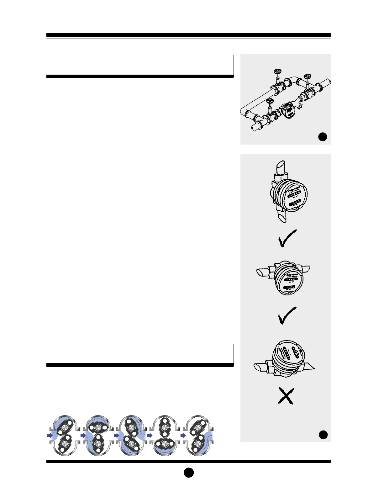
1] GPI recommends that when setting
up pipework for meter installations
a bypass line be included in the
design. This provides the facility for
a meter to be removed for
maintenance without interrupting
production. (See Fig.1)
2] Use thread sealant on all pipe
threads. For flanged versions 2”
ANSI 150lb or DIN16, appropriate
companion flanges and gaskets are
required.
3] For pump applications ensure pipe
work has the appropriate working
pressure rating to match the pressure
output of the pump. The maximum
working pressures are;
2” flanged stainless steel or aluminum
series. See appropriate ANSI/DIN
flange rules.
4] Install a wire mesh strainer (Y or
basket type 40 mesh as close as
possible to the inlet side of the meter.
5] Ensure that the meter is installed so
that the flow of the liquid is in the
direction of the arrows embossed on
the meter body.
6] The meter can be installed in any
orientation as long as the meter
shafts are in a horizontal plane.
(Refer to Fig.2 for correct
installation) The register assembly
may be orientated to suit the
individual installation.
Note: Incorrect installation can cause
premature wear of meter components.
7] Do not over tighten meter connections.
8] It is important that after initial
installation you fill the line slowly,
high speed air purge could cause
damage to the rotors.
9] Test the system for leaks.
10] Check the strainer for swarf or
foreign material, after the first 200
litres check periodically,
particularly if the flow rate
decreases.
2
Installation
When fluid passes through the meter,
rotors turn. The magnets which are
located in the rotors will pass across
the pulser circuit board (containing
either Reed switches or Hall Effect
sensors). A signal is received which is
then sent by the Pulse Circuit Board
(PCB) to the relevant LC display or
receiving instrument.
Operation
1
2
Bypass Line
Flow Outlet
Flow Inlet
Strainer
Do Not Install Meter This Way
Page 4

Disassembly
Ensure that the fluid supply to the
meter is disconnected, and the line
pressure is released before
disassembly, with the exception for
repair or maintenance to the LC
Display or PCB where there is no
necessity to isolate the meter from
flow. Refer to the exploded parts
diagram on pages 7 and 8 for item
numbers.
1a] Units with Pulse Caps; Undo the
conduit connector, remove pulse
cap (item 9) and remove the wires
from the pulse terminal board (item 5).
1b] Standard LC Display; Mark the
display orientation with a marking
pen, unscrew the four large screws
(Item 30) on top of the LC Display.
Carefully separate the LC Display
from the plastic housing and
disconnect the wires from the
Reed Switch Connections for PCB Terminals - refer Fig.3
Hall Effect Sensor Connections - refer Fig.4
3
Electrical Connections
Service Instructions
3
Contact rating 15VA
Maximum Voltage 150VDC
Configuration 1
2 x pulse outputs
Configuration 2
Link 2 & 3 for double
pulse output
LCD Versions
1 x Hall Effect Sensor
1 x Reed Switch
1 - Reed Switch
2 - Reed Switch
3 - HE Common 4 - HE Signal
5 - HE Supply +
Pulse V
ersions Only
2 x Hall Effect Sensor
1 - HE Supply +
2 - HE 1 Signal
3 - HE Common 4 - HE 2 Signal
5 - HE Ground
4
Hall Effect Voltage 4.5 to 24 VDC
Current Draw Minimum 4.6mA
Output NPN Open Collector 25mA
Page 5

This section of the instruction manual
assists you in the operating of the GPI
Standard LC Display. Please take a few
minutes to acquaint yourself with the
information that follows.
Replace Battery
1] Remove the two large screws (Item
30) and the two small screws (Item
31) from the battery cover plate
(Item 29).
2] Remove the battery cover plate
Standard LC Display
4
pulse terminal block. (See Standard
LC Display instructions).
1c] Deluxe LC Display; Mark the
display orientation with a marking
pen, remove the four retaining
screws on the display face (Item
16). Lift off the display unit and
remove the 9 pin connector at the
back of the display unit. (Refer to
separate Deluxe LC Display
instruction manual).
2] Remove the mounting adaptor plate
and gasket (Item 14).
3] Loosen the eight cap head screws
(Item 7) that hold down the meter
cap (Item 4), remove the screws,
washers and lift off the cap.
4] Remove the o’ring (Item 2) from the o’ring
groove in the meter cap (Item 4).
5] Remove rotors (Item 3).
Reassembly
1] Before reassembling check the
condition of the rotors (replace if
necessary).
2] Check that the smooth side of the
rotors (not the plug side) is facing
you when inserting the rotors, the
smooth side of the rotor is the
magnet side. There is no difference
between rotor one or rotor two.
3] Replace the rotors (Item 3) onto the
shafts at 90oto each other (refer Fig.
5) and check their operation by
turning either of the rotors. If the
rotors are not in mesh correctly or
do not move freely, remove one of
the rotors and replace correctly at
90oto the other rotor. Re-check the
operation of the rotors.
4] Replace the o’ring (Item 2) into
groove in the meter cap, if the o’ring
has grown or is damaged in any way
replace it with a new part.
5] Replace the meter cap making sure
that the locating pin in the body
lines up with the hole in the meter
cap. Insert the cap head screws (Item
7) and tighten in the sequence 1, 6,
2, 5, 3, 7, 4, 8.
6] The replacement of cables and
connectors are a reversal of the
disassembly procedure, replace
conduit fitting if required. When
replacing the Standard LC Display or
the Deluxe LC Display, confirm the
orientation marks made on
disassembly are aligned then screw
the register into place.
7] Test the meter by turning the rotors
with a finger or by applying very low
air pressure (no more than a good
breath) to one end of the meter,
before returning the meter to the line.
Pulse Circuit Board (PCB) Notes:
The PCB (Item 5) is fitted with (A) two
reed switches; (B) hall effect sensors; or
(C) one reed switch and one hall effect
sensor. The PCB board is fastened to
the meter cap (Item 4) by two screws
and stand off’s. All care and caution
should be taken when removing or
handling the PCB as both the reed
switch and hall effect sensor are fragile.
Individual reed switches or hall effect
sensors are not available as individual
replacement parts and are only
available with the PCB (Item 5).
5
Rotors must be at 90oto each other.
Rotor #2
Rotor #1
6
Standard LC Display
Page 6

5
(Item 29) and gasket (Item 28).
3] Remove battery, and clean any
corrosion from the battery terminals
(to protect terminals from corrosion
or condensation coat the terminals
with petroleum jelly).
4] Install the new battery.
5] Check gasket (Item 28) for damage
(replace if required). Position gasket
(Item 28) and cover plate (Item 29)
correctly, insert the screws and
tighten.
Display Operation
All meter operations are reflected in the
readout on the face of the meter. The
readout contains three lines of
information; refer to Fig. 7.
Note: The calibration is preset and is
permanently stored in the meter’s
computer.
The meter will turn on automatically
when the liquid flows through the
meter. The meter can also be turned on
manually by pressing and releasing the
display button.
T
urn Off
The meter turns off automatically two
minutes after flow stops. When the
meter is off, the readout is blank.
Batch T
otal
The resettable batch total indicates flow
during a single use. This total can be
reset by holding down the display
button for three seconds until zeros
appear. The batch total can be found by
pressing and releasing the display button
until the bottom line displays “Total 2”.
Cumulative T
otal
The cumulative total is the total of all
the liquid measured since the meter’s
power supply was connected. This total
cannot be manually zeroed, but will
zero when the battery has been
removed, goes dead, or when it
reaches the maximum value of
999,999.
The cumulative total can be found by
pressing and releasing the display
button until the bottom line displays
“Total 1 Locked”.
Flow Rate
The flow rate is the rate the fluid is
flowing through the meter. The flow
rate setting can be found by pressing
and releasing the display button until
the bottom line displays “flow rate”.
Propeller
Any time liquid flows through the
meter, a small propeller displays.
Battery Replacement
Your meter is powered by a 9 volt
lithium battery. (Replacement batteries;
Lithium U9VL, Alkaline 522 or
MN1604). If the meter’s readout should
become dim or blank, the battery
should be replaced.
When the battery either falls or is
disconnected the batch and cumulative
totals return to zero. The factory
calibration is retained in the meter’s
computer permanently and will not be
affected by battery failure.
Auxiliary Facilities
Connection of an external 12 volt DC
power supply facility;
1] Remove the 4 large screws (Item 30)
and remove the register from the
coverplate.
2] Disconnect the internal battery.
3] Solder the external power leads to
the terminals marked ‘Ext 12V’ on
the registers printed circuit board.
4] Re-assemble the register onto the
coverplate, replace the 4 screws
(Item 30) and screw firmly together.
Connection of external pulse output
1] Remove the 4 large screws (Item 30)
and remove the register coverplate.
2] Connect external signal lead. (Refer
Fig. 8)
Pulse O/P and Ext Power are the
connections located on the interface
PCB, to use this output a 1K resistor
will need to be soldered between the +
voltage of the external power input and
the + of the pulse O/P. Pulse signal
represents the output cabling to the
receiving instrument.
7
Top line indicates
“Preset Factory Calibration”
Bottom line indicates
“Totaliser” mode
Middle
line
indicates
“Flow”
Page 7

6
Meter Trouble Shooting
8
1KR (2 watt 1%)
Pulse O/P PCB Connection
Ext Power PCB
Connection 12~24
vdc 100mA
Pulse Signal to Instrument
TROUBLE SHOOTING GUIDE
TROUBLE
Fluid will not flow through meter
Reduced flow through the meter
Meter reading inaccurate
Meter not giving a pulse signal
LCD Register not working
CAUSE
a] Foreign matter blocking rotors
b] Line strainer blocked
c] Damaged rotors
d] Meter connections over tightened
e] Fluid is too viscous
a] Strainer is partially blocked
b] Fluid is too viscous
a] Fluid flow rate is too high or too low
b] Fluid is too viscous
c] Excess wear caused by incorrect
installation
a] Faulty hall effect sensor
b] Faulty reed switch
c] Magnets failed
a] Battery not connected properly
b] Battery flat
c] Faulty wiring connections
d] Faulty LC display
e] Faulty connection from LC display
to Pulse PCB
REMEDY
a] Dismantle meter, clean rotors
(Strainer must be fitted in line)
b] Clean strainer
c] Replace rotors (Strainer must be
fitted in line)
d] Re-adjust connections
e] See specifications for maximum
viscosity
a] Clean strainer
b] See specifications for maximum
viscosity
a] See “specifications” for minimum
and maximum flow rates
b] Consult GPI
c] Check meter body and rotors.
Replace as required. Refer to
installation instructions
a] Replace PCB Board
b] Replace PCB Board
c] Replace magnets
a] Check battery connections
b] Replace battery
c] Check wiring for loose or faulty
connections
d] Replace LC display
e] Check wiring connections
Note: Internal 9 volt battery must be disconnected when using the display pulse output.
Page 8

7
Meter Parts Listing
1
23 4 56 7 8 910
1 1 MS283F Meter Body 2” ANSI 150lb Flange (Aluminium)
1 1 MS281D Meter Body 2” DIN16 Flange (Aluminium)
1 1 MS281F Meter Body 2” ANSI 150lb Flange (S/Steel)
1 1 MS283D Meter Body 2” DIN16 Flange (S/Steel)
21* BS252 “O” Ring (NBR)
21* BS252E “O” Ring (EPDM)
21* BS252TE “O” Ring (Teflon)
21* BS252V “O” Ring (Viton)
32* MS147S Rotors PPS (Polyphenylene Sulfide Resins)
32* MS147TS High Temperature Rotors (PPS)
32* MS147HS High Viscosity Rotors (PPS)
32* MS147HTS HighViscosity/High Temperature Rotors (PPS)
4 1 MS230 Meter Cap (Aluminium)
4 1 MS231 Meter Cap (Stainless Steel)
51* MS201-R PCB (Standard Reed Switch)
51* MS201-HE PCB (Hall Effect Sensor)
5 1 MS201-R/HE PCB ( 1 Reed Switch & 1 Hall Effect Sensor)
6 4 MS284S PCB Board Screws
76* MS243S Meter Cap Screws (Standard)
76* MS282S Meter Cap Screws (Stainless Steel)
81* MS300 Pulser Cap Gasket
9 1 MS160 Pulser Cap (Aluminium) 20mm Conduit Thread
9 1 MS160N Pulser Cap (Aluminum) 1/2” NPT Thread
9 1 MS170 Pulser Cap (Stainless Steel) 20mm Conduit Thread
9 1 MS170N Pulser Cap (Stainless Steel) 1/2” NPT Thread
10 4 MS115S Pulser Cap Screw (Stainless Steel)
11 1 MS37 Warning Lebel (Not Shown)
12 1 MS14 Explosion Proof Approval Label (Not Shown)
13 1 Customer to Specify Legend Plate (Not Shown) inc. Hammer Screws
Item
No.
No.
Off.
Part or Set
(Order from this column only)
Part Description
Key:
u Indicates recommended Spare Parts to stock
Bold text indicates Stainless Steel Model Parts
Rec.
Parts
Page 9

8
MS280S Deluxe LCD Display (Complete)
14 1 MS279 Mounting Adaptor Plate
15 4 * MS117S Adaptor Screws
16 1 * MS69 LC Display Unit
17 4 * MS118S LC Display Mounting Screws
18 1 * MS127 Battery Retaining Screw
19 1 * MS126 Battery (Standard) CR2040
20 1 * MS68 Connector and Cable (Not Shown)
21 1 MS87 PTB Approval Label (Not Shown)
22 1 * MS128 Extended Life Battery 2/3 AA (Not Shown)
NOTE: Note Suitable for Intrinsic Use
33 1 * MS307 Gasket
MS275S Standard LC Display (Complete)
23 1 MS238 Mounting Adaptor Plate
24 4 * MS203S Adaptor Screws
25 1 * BS045 “O”Ring
26 1 * MS205 LC Display
27 1 * MS274 9 Volt Battery
28 1 * MS184S (Inc. MS184B) Battery Gasket
29 1 * MS184S (Inc. MS184A) Battery Cover
30 4 * MS206S Register Screws
31 4 * MS182S Battery Cover Plate Screws
32 1 Customer to Specify Battery Cover Label
Display Parts Listing
823242526282930
27
32 31
814
15
18 19
1716
33
Item
No.
No.
Off.
Part or Set
(Order from this column only)
Part Description
Rec.
Parts
Page 10

9
Meter Specifications
Heating Jackets
Meter Type
Flow Ranges
(Litres per minute/US Gallons per
minute)
Above 5 Centipoise
Below 5 Centipoise
Accuracy of Reading
Maximum Viscosity*
Maximum Operating Pressure
Maximum Operating Temperature
Pulse Type
Pulses Per Litre/US Gallon
Pulse
15 to 350/ 4 to 92
33 to 300/ 9 to 79
+/- 0.5%
1000 Centipoise
As per flange rule
80°C/ 176°F
Dual Reed Switches or
Hall Effect Sensor or
combination HE
Sensor/Reed Switch
6.68/ 13.3 or 25.28/ 50.34
Pulse with Standard
LC Display
15 to 350/ 4 to 92
33 to 300/ 9 to 79
+/- 0.5%
1000 Centipoise
As per flange rule
80°C/ 176°F
Dual Reed Switches or
Hall Effect Sensor or
combination HE
Sensor/Reed Switch
6.68/ 13.3 or 25.28/ 50.34
Pulse with Deluxe
LC Display
15 to 350/ 4 to 92
33 to 300/ 9 to 79
+/- 0.5%
1000 Centipoise
As per flange rule
80°C/ 176°F
Dual Reed Switches or
Hall Effect Sensor or
combination HE
Sensor/Reed Switch
6.68/ 13.3 or 25.28/ 50.34
1
2
3
Complete Assembly: GHJ500-1 - Aluminium BSP
GHJ500-2 - Aluminium NPT
Spare Parts Listing:
GHJ400-1: MS333 SHCS Screws
MS133B Jacket Body - Aluminium/BSP
BS156 “O” Ring
GHJ400-2: MS333 SHCS Screws
MS133N Jacket Body - Aluminium/NPT
BS156 “O” Ring
* Unless High Viscosity or High Temperature Rotors are fitted
Page 11

178mm
102mm
185mm
55
mm
10
Meter Dimensions
178mm
86mm
188mm
18mm
55mm
137mm
178
mm
55mm
GM50 Pulse Meter Dimensions
GM50 Pulse Meter with Standard LC Display
GM50 Pulse Meter with Deluxe LC Display
240mm
152mm
213mm
210mm
240mm
152mm
210mm
240
mm
127
mm
235mm
152mm
Page 12

Warranty
Great Plains Industries, Inc. Limited Warranty Policy
Great Plains Industries, Inc., 5252 East 36th Street North, Wichita, Kansas USA 67220-3205,
hereby provides a limited one year warranty against defects in material and workmanship on
all products manufactured by Great Plains Industries, Inc. This warranty shall extend to the
purchaser of this product and to any person to whom such product is transferred during the
warranty period.
The warranty period shall begin on the date of the original new equipment purchase.
Warrantor’s obligation hereunder shall be limited to repairing defective workmanship or
replacing or repairing any defective part or parts. This warranty shall not apply if:
a.)The product has been altered or modified outside the warrantor’s duly appointed
representative;
b.)The product has been subjected to neglect, misuse, abuse or damage or has been installed
or operated other than in accordance with the manufacturer’s operating instructions.
To make a claim against this warranty, notice of claim must be given in writing to the company
at its address below no later than 30 days after the expiration of the warranty period. Such
notice shall identify the defect in the product. The company shall, within 14 days of receipt of
such notice, notify the customer to either send the product, transportation prepaid, to the
company at its office in Wichita, Kansas, or to a duly authorized service center. The company
shall perform all obligations imposed on it by the terms of this warranty within 60 days of
receipt of the defective product.
GREAT PLAINS INDUSTRIES, INC. EXCLUDES LIABILITY UNDER THIS WARRANTY FOR
DIRECT, INDIRECT, INCIDENTALAND CONSEQUENTIAL DAMAGES INCURRED IN THE
USE OR LOSS OF USE IF THE PRODUCT WARRANTED HEREUNDER.
The company herewith expressly disclaims any warranty of merchantability or fitness for any
particular purpose other than for which it was designed.
This warranty gives you specific rights and you may also have other rights which vary from
U.S. state to U.S. state.
NOTE: In compliance with MAGNUSON MOSS CONSUMER WARRANTY ACT - Part 702
(governs the resale availability of the warranty terms).
 Loading...