

Page 1
MS499G
0603
0003
Positive Displacement Flowmeters
GM007 series instruction manual
GM007 Pulse Meter From serial No. CXXXX
Page 2
Thank you for purchasing a GPI GM
Series Flow Meter. Please take a few
minutes to read through this manual
before installing and operating your
meter. If you have any problems with
the meter, refer to the maintenance
and trouble shooting sections of this
manual.
This manual contains connection and
operating instructions for the GM007
Series meters with pulse outputs. For
models with displays an additonal
instruction manual is supplied. [If you
need further assistance, contact your
local GPI representative or contact
GPI by telephone or fax.]
The GPI GM Series Flow Meter has
incorporated the oval rotor principal
into its design. This has proven to be a
reliable and highly accurate method
of measuring flow. Exceptional
repeatability and high accuracy over a
wide range of fluid
viscosities and flow rates are features
of the GM Series flow meter design.
The low pressure drop and high
pressure rating means the GM Series
flow
meter is suitable for both gravity and
pump (in line) applications.
The GPI GM Series flow meters are
available in aluminum, 316 stainless
steel, or PPS. Standard rotors are made
from PPS (Polyphenylene Sulfide
Resins) with optional 316 stainless
steel rotors available for either
stainless steel or aluminium models.
PLEASE READ THIS INFORMATION
CAREFULLY BEFORE USE!
Before use, confirm the fluid to be used
is compatible with the meter (refer to
the GPI fluid compatibility chart), or
consult your local GPI distributor for
advice.
To prevent damage from dirt or foreign
matter, GPI recommends a Y or Basket
type 60 mesh strainer be installed as
close as possible to the inlet side of the
meter (if required contact GPI for
further information).
Note: When a strainer is installed it
should be regularly inspected and
cleaned. Failure to keep the strainer
clean will dramatically effect flow
meter performance.
To prevent damage to the meter slowly
fill the system with fluid (this will
prevent damage caused by air purge).
Note: Failure to do this could damage
the meter.
For pump applications, turn off the
pump at the end of each day.
Maintenance can be carried out to the
liquid crystal displays and pulse units
without removing or isolating the meter
from the line. When maintenance to
any other part of the meter is required,
the meter must be isolated and the line
pressure reduced.
The reed switch pulse unit can cause
inaccurate rate counts when used with
high speed counters. It is advised that
a debounce circuit be used or
alternatively use the hall effect sensor
option.
1
To the owner
Important Information
Page 3
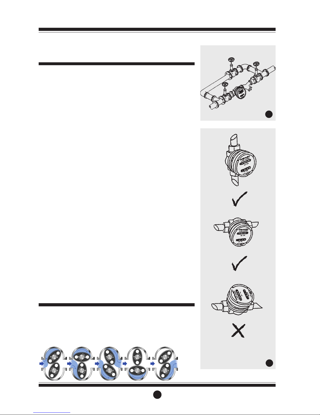
1] GPI recommends that when setting
up pipework for meter installations
a bypass line be included in the
design. This provides the facility for
a meter to be removed for
maintenance without interrupting
production. (See Fig.1)
2] Use thread sealant on all pipe
threads.
3] For pump applications ensure pipe
work has the appropriate working
pressure rating to match the
pressure output of the pump.
4] Install a wire mesh strainer (Y or
basket type 60 mesh as close as
possible to the inlet side of the
meter.
5] Ensure that the meter is installed so
that the flow of the liquid is in the
direction of the arrows embossed
on the meter body.
6] The meter can be installed in any
orientation as long as the meter
shafts are in a horizontal plane.
(Refer to Fig.2 for correct
installation) The register assembly
may be orientated to suit the
individual installation.
Note: Incorrect installation can cause
premature wear of meter
components.
7] Do not over tighten meter
connections.
8] It is important that after initial
installation you fill the line slowly,
high speed air purge could cause
damage to the rotors.
9] Test the system for leaks.
10] Check the strainer for swarf or
foreign material, after the first 200
litres check periodically,
particularly if the flow rate
decreases.
2
Installation
When fluid passes through the meter,
the rotors turn. The magnets which are
located in the rotors will pass across
the pulser circuit board (containing
either Reed switches or Hall Effect
sensors). A signal is received which is
then sent by the Pulse Circuit Board
(PCB) to the relevant LC display or
receiving instrument.
Operation
1
2
Bypass Line
Flow Outlet
Flow Inlet
Strainer
Do Not Install Meter This Way
Page 4

Disassembly
Ensure that the fluid supply to the
meter is disconnected, and the line
pressure is released before
disassembly, with the exception for
repair or maintenance to the LC
Display or PCB where there is no
necessity to isolate the meter from the
flow. Refer to the exploded parts
diagram on pages 5.
1a] Units with Pulse Caps; Undo the
conduit connector, remove pulse cap
(item 9) and remove the wires from the
pulse terminal board (item 5).
1b] Standard LC Display; Mark the
display orientation with a marking
pen, unscrew the four large
screws on top of the LC Display.
Reed Switch Connections for PCB Terminals - refer Fig.3
Hall Effect Sensor Connections - refer Fig.4
3
Electrical Connections
Service Instructions
3
Contact rating 15VA
Maximum Voltage 150VDC
Configuration 1
2 x pulse outputs
Configuration 2
Link 2 & 3 for double
pulse output
LCD Versions
1 x Hall Effect Sensor
1 x Reed Switch
1 - Reed Switch
2 - Reed Switch
3 - HE Common 4 - HE Signal
5 - HE Supply +
Pulse V
ersions Only
2 x Hall Effect Sensor
1 - HE Supply +
2 - HE 1 Signal
3 - HE Common 4 - HE 2 Signal
5 - HE Ground
4
Hall Effect Voltage 4.5 to 24 VDC
Current Draw Minimum 4.6mA
Output NPN Open Collector 25mA
Page 5

4
Carefully separate the LC Display
from the plastic housing and
disconnect the wires from the
pulse terminal block.
2] Remove the mounting adaptor plate
and gasket (Item 8).
3] Loosen the four cap screws (Item 7)
and nuts that hold down the meter
cap (Item 4), remove the screws
and nuts and lift off the cap.
4] Remove the o’ring (Item 2) from the
o’ring groove in the meter cap (Item 4).
5] Remove rotors (Item 3).
Reassembly
1] Before reassembling check the
condition of the rotors (replace if
necessary).
2] Check that the smooth side of the
rotors (not the plug side) is facing
you when inserting the rotors, the
smooth side of the rotor is the
magnet side. There is no difference
between rotor one or rotor two.
3] Replace the rotors (Item 3) onto the
shafts at 90oto each other (refer
Fig. 5) and check their operation by
turning either of the rotors. If the
rotors are not in mesh correctly or
do not move freely, remove one of
the rotors and replace correctly at
90oto the other rotor. Re-check the
operation of the rotors.
4] Replace the o’ring (Item 2) into
groove in the meter cap, if the
o’ring has grown or is damaged in
any way replace it with a new part.
5] Replace the meter cap. Insert the
cap head screws (Item 7) and fix
nuts and tighten in the sequence 1,
3, 2, 4
6] The replacement of cables and
connectors are a reversal of the
disassembly procedure, replace
conduit fitting if required. When
replaceing the Standard LC Display,
confirm the orientation marks made
on disassembly are aligned then
screw the register into place.
7] Test the meter by turning the rotors
with a finger or by applying very low
air pressure ( a good breath) to one
end of the meter, before returning
the meter to the line.
Pulse Circuit Board (PCB) Notes:
The pulse PCB (Item 5) is fitted with
(A) two reed switches; (B) hall effect
sensors; or (C) one reed switch and
one hall effect sensor. The PCB board
is fastened to the meter cap (Item 4)
by two screws and stand off’s. All care
and caution should be taken when
removing or handling the PCB as both
the reed switch and hall effect sensor
are fragile.
Individual reed switches or hall effect
sensors are not available as
replacement parts and are only
available with the PCB (Item 5).
5
Rotors must be at 90oto each other.
Rotor #2
Rotor #1
Meter Trouble Shooting
TROUBLE
Fluid will not flow through meter
Reduced flow through the meter
Meter reading inaccurate
Meter not giving a pulse signal
CAUSE
a] Foreign matter blocking rotors
b] Line strainer blocked
c] Damaged rotors
d] Meter connections over tightened
e] Fluid is too viscous
a] Strainer is partially blocked
b] Fluid is too viscous
a] Fluid flow rate is too high or too low
b] Fluid is too viscous
c] Excess wear caused by incorrect
installation
a] Faulty hall effect sensor
b] Faulty reed switch
c] Magnets failed
REMEDY
a] Dismantle meter, clean rotors
(Strainer must be fitted in line)
b] Clean strainer
c] Replace rotors (Strainer must be
fitted in line)
d] Re-adjust connections
e] See specifications for rated viscosity
a] Clean strainer
b] See specifications for rated viscosity
a] See “specifications” for flow range
b] Bleed air from system
c] Check meter body and rotors.
Replace as required.
a] Replace PCB Board
b] Replace PCB Board
c] Replace rotors
Page 6

5
Meter Parts Listing
1
23 4 56 7 8 9 10
1 1 MS351B Meter Body 1” BSP (PPS) & St St Shafts
1 1 MS351N Meter Body 1” NPT (PPS) & St St Shafts
1 1 MS352B Meter Body 1” BSP (PPS) & Hastalloy Shafts
1 1 MS352N Meter Body 1” NPT (PPS) & Hastalloy Shafts
21u BS235TE “O” Ring (Teflon) Encapsulated
21u BS235V “O” Ring (Viton)
32u MS370S Rotors PPS (Polyphenylene Sulfide Resins)
3 2 MS370CPS Rotors PPS **
4 1 MS405R Meter Cap (PPS)
51u MS368-R PCB (Standard Reed Switch)
51u MS344-HE PCB (Hall Effect Sensor)
5 1 MS368-R/HE PCB ( 1 Reed Switch & 1 Hall Effect Sensor)
6 2 MS284S PCB Board Screws
74u MS350S Meter Cap Screws (Stainless Steel)
81u MS340 Pulser Cap Gasket
9 1 MS406R Pulser Cap (PPS) 16mm Conduit Thread
9 1 MS406R-N Pulser Cap (PPS) 1/2” NPT Thread
10 2 MS347S Pulser Cap Screw (Stainless Steel)
11 1 MS37 Warning Label (Not Shown)
12 1 Specify plate details Legend Plate (Not Shown) inc. Hammer Screws
33 1 MS111 Earthing Screw
34 4 MS497S Nut - Stainless Steel - Not Shown, recessed in body
**For PPS Meters fitted with Hastalloy shafts only
Item
No.
No.
Off.
Part or Set
(Order from this column only)
Part Description
Key:
u Indicates recommended Spare Parts to stock
Rec.
Parts
33
Meter Specifications
Flow Ranges (Litres/min. - US Gall./min.)
Above 5 Centipoise
Below 5 Centipoise
Accuracy of Reading
Maximum Viscosity
Maximum Operating Pressure
Maximum Operating Temperature
Pulse Type
Pulses Per Litre/US Gallon
3 to 80 / 0.8 to 21
8 to 70 / 2 to 18.5
+/- 0.5%
1000 Centipoise
1000 kPa/ 150 PSI/ 10 BAR
80°C/ 176°F
Dual Reed Switches or Hall Effect Sensor or
combination HE Sensor/Reed Switch
52 or 104/197 or 394
Page 7

Warranty
Great Plains Industries, Inc. Limited Warranty Policy
Great Plains Industries, Inc., 5252 East 36th Street North, Wichita, Kansas USA 67220-3205, hereby provides a limited one
year warranty against defects in material and workmanship on all products manufactured by Great Plains Industries, Inc. This
warranty shall extend to the purchaser of this product and to any person to whom such product is transferred during the
warranty period.
The warranty period shall begin on the date of the original new equipment purchase. Warrantor’s obligation hereunder shall
be limited to repairing defective workmanship or replacing or repairing any defective part or parts. This warranty shall not
apply if:
a.)The product has been altered or modified outside the warrantor’s duly appointed representative;
b.)The product has been subjected to neglect, misuse, abuse or damage or has been installed or operated other than in
accordance with the manufacturer’s operating instructions.
To make a claim against this warranty, notice of claim must be given in writing to the company at its address below no later
than 30 days after the expiration of the warranty period. Such notice shall identify the defect in the product. The company
shall, within 14 days of receipt of such notice, notify the customer to either send the product, transportation prepaid, to the
company at its office in Wichita, Kansas, or to a duly authorized service center. The company shall perform all obligations
imposed on it by the terms of this warranty within 60 days of receipt of the defective product.
GREAT PLAINS INDUSTRIES, INC. EXCLUDES LIABILITY UNDER THIS WARRANTY FOR DIRECT, INDIRECT,
INCIDENTAL AND CONSEQUENTIAL DAMAGES INCURRED IN THE USE OR LOSS OF USE IF THE PRODUCT
WARRANTED HEREUNDER.
The company herewith expressly disclaims any warranty of merchantability or fitness for any particular purpose other than for
which it was designed.
This warranty gives you specific rights and you may also have other rights which vary from U.S. state to U.S. state.
NOTE: In compliance with MAGNUSON MOSS CONSUMER WARRANTY ACT - Part 702
(governs the resale availability of the warranty terms).
Meter Dimensions
70mm
108mm
120mm
18mm
30
mm
Pulse Meter Dimensions
100mm
 Loading...