

Page 1
5252 East 36th Street North
Wichita, KS USA 67220-3205
TEL: 316-686-7361
FAX: 316-686-6746
1- 888 -99 6-3 837
SAVE THESE INSTRUCTIONS
GPI 4-20 mA Out with Display
Owner’s Manual
Local Models
GX510
To the owner…
Congratulations on receiving your GPI 4-20 mA Out with
Display. We are pleased to provide you with a product
designed to give you maximum reliability and efficiency.
Our business is the design, manufacture, and marketing of
liquid handling, agricultural, and recreational products. We
succeed because we provide customers with innovative,
reliable, safe, timely, and competitively-priced products. We
pride ourselves in conducting our business with integrity and
professionalism.
We are proud to provide you with a quality product and the
support you need to obtain years of safe, dependable service.
President
Great Plains Industries, Inc.
Display information in this manual supersedes display information provided with your meter.
GM Series
(Shown here on GM001)
Remote Model
GX500
TABLE OF CONTENTS
General Information ............................................................. 2
Safety Instructions ............................................................... 2
Installation ........................................................................... 2
Wiring .................................................................................. 3
Configuration ....................................................................... 9
Operation ............................................................................. 9
Calibration ........................................................................... 9
K-Factor Method Calibration Procedures ........................... 9
Correction Factor Method Calibration Procedures ........... 10
Maintenance ...................................................................... 12
Troubleshooting ................................................................. 13
Dimensional Drawings ....................................................... 14
Illustrated Parts Drawing ................................................... 15
Specifications - Local ........................................................ 16
Specifications - Remote .................................................... 17
Service ............................................................................... 18
WEEE Directive .................................................................. 18
06/10
Rev. H 920765-05
1
Page 2
GENERAL INFORMATION
SAFETY INSTRUCTIONS
This manual will assist you in operating and maintaining
the GPI electronics supplied with your GPI meter or as an
accessory unit on both local and remote models. The GPI
Electronics can be used in indoor or outdoor applications
where occasional exposure to moisture is common.
• The 4-20 mA Out with Display is available in two versions. One indicates flowrate in units/minute and one
in units/hour. Both indicate flow totals in gallons and
litres.
• The 4-20 mA Out with Display can be used on all GPI
models, including the Precision G series, the Industrial
Grade G2 series, the Commercial Grade A1 series,
and the positive displacement GM series oval gear
meters.
Product differences in this manual are identified by either,
Local or Remote as necessary.
If the meter was purchased with this display, then it will come
calibrated from the factory for gallons “GAL” and litre “LTR”.
Field calibration is also available.
If the unit was purchased as an accessory or remote, the
calibration has not been entered and the end user will need
to configure and calibrate the display.
The GPI 4-20 mA Out with Display is a flow totalizer and rate
meter with industry standard current loop output. The unit is
loop powered, and provides a 4-20 mA analog output proportional to the frequency signal for communication with PLCs
and other customer equipment. The 4-20 mA (or 0-20 mA)
output is calibrated under actual flow conditions with simple
push-button calibration. Auxiliary output includes 0-5 VDC.
The microprocessor-based electronics have extremely low
power requirements and are completely powered by the
4-20 loop. The electronics provides the options of local (on
the meter) and/or remote (up to 5,000 feet) display. Flow total
and rate are displayed on a large 6-digit LCD readout with
two-point floating decimal for totals from .01 to 999,999. All
operations are easily accessed with the push buttons on the
display front panel.
CAUTION
This unit is not FM Approved. Therefore, use of this
transmitter with an approved metering system voids
FM Approval.
NOTE: This unit is loop powered, requiring an input power
supply of 8.5 to 35 volts (24 VDC is recommended).
NOTE: Setpoint calibration of the unit is required for the 4-20
mA, 0-20 mA, and 0-5 V output options.
• When measuring flammable liquids, observe precautions against fire or explosion.
• When working in hazardous environments, always
exercise appropriate safety precautions.
• When applying external power to the transmitter, use
DC power only.
• Disconnect external power to the transmitter before
detaching or attaching input or output wires.
• Ground loops between sensor and user equipment can
damage the transmitter and can be dangerous.
• If you cannot galvanically isolate the sensor from earth
ground, you may need to use the transmitter’s optically
isolated inputs.
• Be sure O-rings and seals are kept in good repair.
INSTALLATION
CAUTION
Installation should be performed only by qualified
personnel, and in accordance with local governing
regulations.
The following installation guidelines are separated by meter
series and mounting type.
Precision G Series:
• Local – The GX510 4-20 mA Out with Display mounts
directly to the 1 inch MNPT conduit connector.
• Remote – The GX500 4-20 mA Out with Display
connects via an output cable as shown in the Wiring
Diagram.
Industrial Grade G2 Series:
• Local – The GX510 4-20 mA Out with Display requires
the GPI Conduit Connector Kit (Part #113437-01) for
local mounting to the G2 series meter.
• Remote – The GX500 4-20 mA Out with Display
connects via an output cable as shown in the Wiring
Diagram.
Commercial Grade A1 Series:
• Local – The GX510 4-20 mA Out with Display requires
the GPI Conduit Connector Kit (Part #113437-01) for
local mounting to the A1 series meter.
• Remote – The GX500 4-20 mA Out with Display
connects via an output cable as shown in the Wiring
Diagram.
2
GM Oval Gear Series:
• Local – The 4-20 mA Out with Display is mounted
directly to the oval gear meter housing.
Page 3
• Remote – The GX500 4-20 mA Out with Display connects via an output cable as shown in the Wiring Diagram.
Mount the GPI 4-20 mA Out with Display using bolts, screws
or standard U-bolts for pipes. Mounting options include:
• Wall
• Pipe
• Meter (1 inch FNPT conduit connection required)
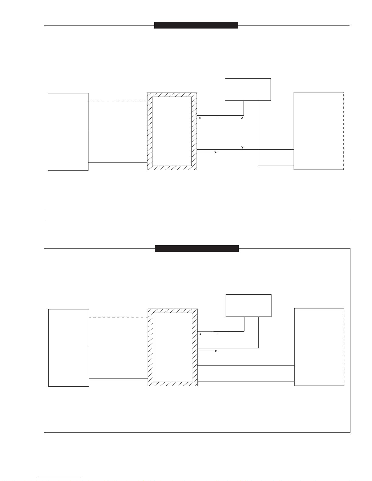
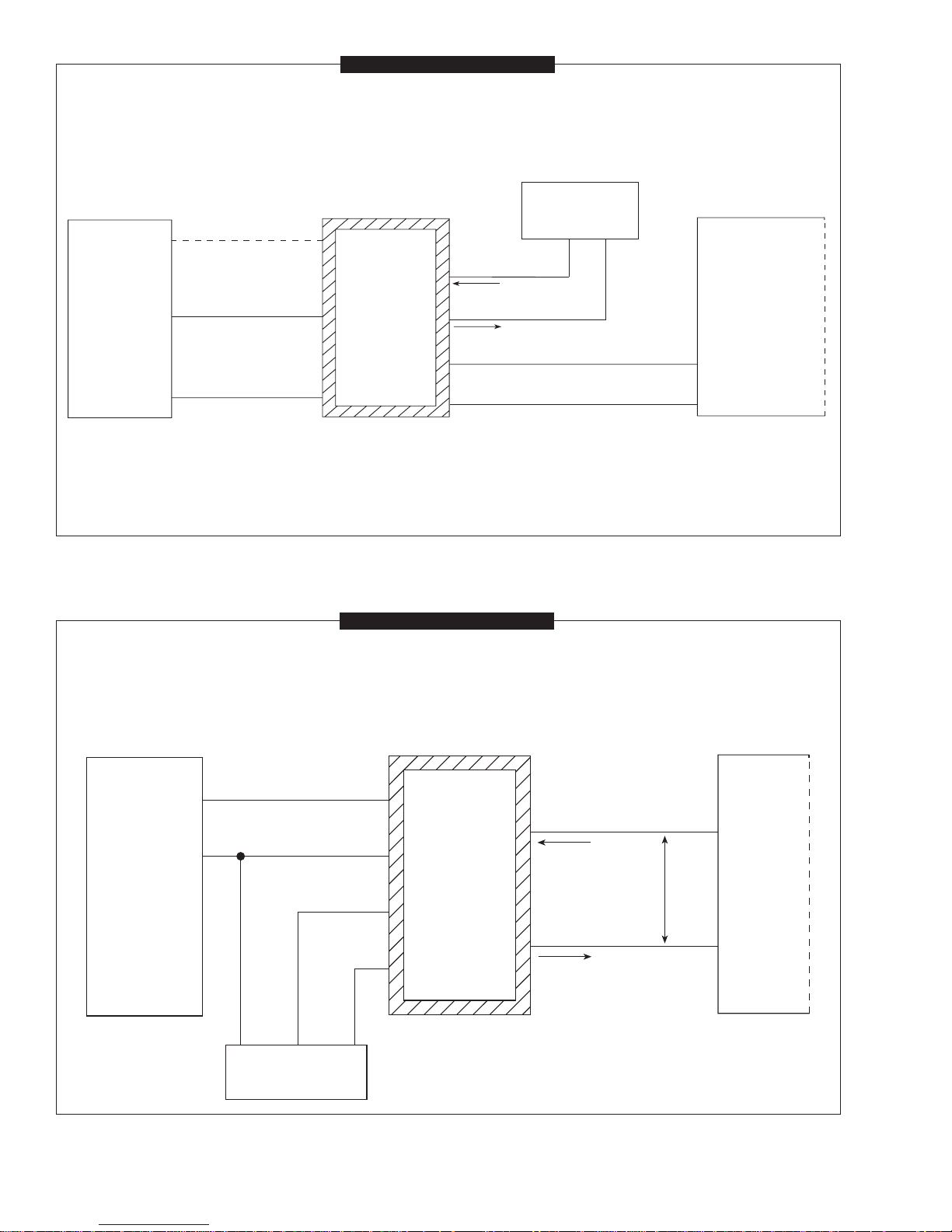
WIRING
This manual refers to various models of GPI flowmeters.
Determine what type of input the electronics will receive and
what type of output, if any, you require. Use the diagrams
found in the wiring diagrams section (if the unit is not already
wired) to correctly wire the system.
The display is externally powered by the loop.
NOTE: Totals will be lost with loss of power on loop.
Environmental
Choose a mounting location suitable for the 4-20 mA Out with
Display. The ideal mounting location is where the:
• flowmeter is as close as possible.
• mounting surface has minimal vibration.
• ambient temperature is +32°F to +140°F (0°C to
+60°C).
• cable lengths are minimal.
Avoid mounting locations where the 4-20 mA Out with Display is:
• subject to constant exposure to water or other liquids
(occasional low-pressure splashing will not harm unit
if cable entry points are well-sealed).
• subject to > 5g shock loading.
• facing the sun directly for long periods of time.
• close to high voltage/current runs, DC motors, internal
combustion engines, or frequency inverters.
Cable Guidelines
4-20 mA Current Loop:
• The current loop itself is very resistant to electrical noise
pickup and shielded cable is seldom needed except in
very “noisy” (electrical) locations and/or when very long
runs (thousands of feet) are used.
Sensor Cabling:
• Some products come with 20 ft. of shielded cable.
• If you require a longer cable, a 100 ft. cable kit is available from GPI, or use Belden 9363 cable. When wiring
longer lengths of cable, be sure to connect the shield
to LOCAL-COM ONLY! (Multiple shield connections
may cause ground-loop problems).
• Some trial and error may be needed because of the wide
variety of user conditions. Try to keep cable lengths
short!
CAUTION
Determine maximum power supply voltage after determining maximum allowable voltage of all electronic
devices in the system.
The 4-20 mA Out with Display may come with 20 ft. of cable
to connect to the meter. The customer must supply the communication loop cable. Although the unit is usually powered
through the communication loop, there are some circumstances that might require external power.
Connecting the Equipment:
• Remove the faceplate by removing the four (4) corner
screws.
• Attach wiring from your equipment according to the
following terminal connections and wiring diagrams,
depending on your circumstances.
Terminal Connections
Remote Transmitter INPUTS / OUTPUTS
ISO-IN COM: Return for
isolated inputs
ISO-LF IN: Optically-Isolated
High-level Low-frequency
Input
ISO-HF IN: Optically-Isolated
High-level High-frequency
Input
HL-LF IN: High-level Low-
frequency Input. 150 Hz
maximum
COIL-A IN: Low-level
Sinewave Input
COIL-B IN: Low-level
Sinewave Input
HL-HF IN: High-level High-
frequency Input
EDM PWR: Local Vcc. Regu-
lated 5-VDC internal power.
This terminal can supply up
to approximately 2.5 mA,
continuously, to external
circuitry. Typical load/line regulation under ordinary conditions is about ± 10%
LOCAL COM: Local Common
0-5 V OUT: 0 to 5 V Voltage Output. Frequency to Analog Output.
PULSE OUT: Pulse-Out Frequency Output Signal. It is an “open-collector” output
(also known as “n-p-n” or “current-sinking”), referenced to transmitter Local-
Common
LOOP (–): 4 to 20 mA Current Loop – current into transmitter
LOOP (+): 4 to 20 mA Current Loop – current out of transmitter
ISO-IN COM
ISO-LF IN
ISO-HF IN
HL-LF IN
COIL-A IN
COIL-B IN
HL-HF IN
EDM PWR
LOCAL COM
LOCAL COM
0-5 V OUT
PULSE OUT
LOOP (–)
LOOP (+)
3
Page 4
W I R I N G D I A G R A M 1
— 4-20 mA or 0-20 mA Output —
Customer Equipment with Built-in Power Supply
Input: Turbine Mounted Display or Conditioned Signal Sensor (Open Collector)
Output: Customer Equipment, 0-20 mA Sensing, Built-in Loop Power Supply
INPUTS OUTPUTS
Ext. Power
(Red)
GPI
Meter
Note Regarding Resistor “R”: R not generally required for distance up to 25 ft.
Use R = 10k (10000 ohms) for distance up to 50 ft.
Use R = 5.1k (5100 ohms) for distance up to 100 ft.
Use R = 2.7k (2700 ohms) for distance up to 250 ft.
Do not use R less than 2.4k (ohms)
Pulse Out
(White)
Common
(Black)
Shield recommended.
If used, connect to
transmitter’s local
com ONLY!
EDM Power
R
(See note)
HL-HF IN
Local Com
W I R I N G D I A G R A M 2
— 4-20 mA or 0-20 mA Output —
Customer Equipment With Built-in Power Supply – High Temp Applications
Input: Standard Remote Sensor (Variable Reluctance Pickup Coil)
Output: Customer Equipment, 0-20 mA Sensing, Built-in Loop Power Supply
4-20 mA Out
with Display
Loop (+)
(current)
Min. V = 8.5
Max. V = 35
Loop (–)
(current)
CAUTION: Whe n reassembling the f ac ep la te ,
make sure that the enclosure seal is not
crimped or twisted. Do not over-tighten
corner screws (hand tighten only). Faceplate can be rotated 90°.
Customer
Equipment
GPI Meter
Unpowered
Pickup Coil
Only
➤ Minimum signal amplitude required for normal operation approx. 15 mV P-P
➤ Recommended cable type – twisted pair with shield
➤ Recommended maximum cable length – 20 ft.
Coil-A
Coil-B
Shield recommended.
Connect shield to
transmitter’s local
com ONLY!
4
INPUTS OUTPUTS
4-20 mA Out
with Display
Coil-A
Coil-B
Local Com
Loop (+)
(current)
Min. V = 8.5
Max. V = 35
Loop (–)
(current)
CAUTION: Whe n reassembling the f ac ep la te ,
make sure that the enclosure seal is not
crimped or twisted. Do not over-tighten
corner screws (hand tighten only). Faceplate can be rotated 90°.
Customer
Equipment
Page 5
W I R I N G D I A G R A M 3
— 4-20 mA or 0-20 mA Output —
Customer Equipment Without Built-in Power Supply
Input: Turbine Mounted Display or Conditioned Signal Sensor (See inputs from Diagram 1) Standard Remote Sensor (See inputs from Diagram 2)
Output: Customer Equipment, 0-20 mA Sensing, Separate Power Supply
Loop Power Supply
Typ 12 – 24 VDC
(+)
(current)
Min. V = 8.5
Max. V = 35
(current)
(–)
CAUTION: Whe n reassembling the f ac ep la te ,
make sure that the enclosure seal is not
crimped or twisted. Do not over-tighten
corner s crews (hand tighten only).
Faceplate can be rotated 90°.
Customer Equipment
Loop (+) Input
Loop (–) Input
Frequency-Generating
Input Device
NOTE: Minimum loop power supply voltage required:
8.5V + (Max - Customer - Equipment - Drop) +
(Wiring - IR - Drop)
INPUTS OUTPUTS
4-20 mA Out
with Display
W I R I N G D I A G R A M 4
Loop (+)
Loop (–)
— 0-5 V Output —
Customer Equipment Without Built-in Power Supply
Input: Turbine Mounted Display or Conditioned Signal Sensor (See inputs from Diagram 1) Standard Remote Sensor (See inputs from Diagram 2)
Output: Customer Equipment, 0-5 V Sensing, Separate Loop Power Supply
Frequency-Generating
Input Device
NOTE 1: Loop power supply electrically isolated
from customer equipment
NOTE 2: Actual value of loop current (mA) is
disregarded
INPUTS OUTPUTS
4-20 mA Out
with Display
Loop (+)
Loop (–)
0-5 V Output
Local Com
Loop Power Supply
Typ 12 – 24 VDC
(+)
(current)
(current)
(–)
CAUTION: Whe n reassembling the f ac ep la te ,
make sure that the enclosure seal is not
crimped or twisted. Do not over-tighten
corner screws (hand tighten only). Faceplate can be rotated 90°.
Customer Equipment
0-5 V Analog Input (+)
Analog In Return (–)
5
Page 6
W I R I N G D I A G R A M 5
— Pulse Output —
Customer Equipment Without Built-in Power Supply
Input: Turbine Mounted Display or Conditioned Signal Sensor (See inputs from Diagram 1) Standard Remote Sensor (See inputs from Diagram 2)
Output: Customer Equipment, Frequency Sensing, Separate Loop Power Supply
INPUTS OUTPUTS
Frequency-Generating
Input Device
NOTE 1: Loop power supply electrically isolated
from customer equipment
NOTE 2: Actual value of loop current (mA) is
disregarded
Customer Equipment with Built-in Power Supply
Output: Customer Equipment, 0-20 mA Sensing, Built-in Loop Power Supply
Loop Power Supply
Typ 12 – 24 VDC
4-20 mA Out
with Display
W I R I N G D I A G R A M 6
Loop (+)
(current)
Loop (–)
(current)
Pulse Out
Local Com
(+)
(–)
CAUTION: Whe n reassembling the f ac ep la te ,
— 4-20 mA or 0-20 mA Output —
Input: Reed Switch
Customer Equipment
Open-Collector Pulse In
Pulse-In Return
make sure that the enclosure seal is not
crimped or twisted. Do not over-tighten
corner screws (hand tighten only). Faceplate can be rotated 90°.
GPI
Meter
* Optional to use HL-HF IN
Signal
Common
Black Blue Red
PCB Assembly
INPUTS OUTPUTS
* HL-LF IN
Local Com
GPI
4-20 mA Out
Pulse Out
EDM Pwr
with Display
Loop (+)
Loop (–)
(current)
Min. V = 8.5
Max. V = 35
(current)
CAUTION: Whe n reassembling the f ac ep la te ,
make sure that the enclosure seal is not
crimped or twisted. Do not over-tighten
corner screws (hand tighten only). Faceplate can be rotated 90°.
Customer
Equipment
6
Page 7

Output: Customer Equipment, 0-20 mA Sensing, Built-in Loop Power Supply
HE Power Supply
4.5 - 24 VDC
(+) (–)
Supply (+)
W I R I N G D I A G R A M 7
— 4-20 mA or 0-20 mA Output —
Customer Equipment With Built-in Power Supply
Input: Hall Effect
INPUTS OUTPUTS
*
Signal
GPI
Meter
*
Note: Hall Effect requires dedicated power supply.
Common (–)
Black Blue Red
Input: Reed Switch (See inputs from Diagram 6) or Hall Effect* (See inputs from Diagram 7)
PCB Assembly
HL-HF IN
Local Com
Pulse Out
EDM Pwr
W I R I N G D I A G R A M 8
GPI
4-20 mA Out
with Display
Loop (+)
(current)
Customer
Min. V = 8.5
Max. V = 35
Loop (–)
(current)
CAUTION: When reassembling the faceplate, make sure that the enclosure
seal is not crimped or twisted. Do not over-tighten corner screws
(hand tighten only). Faceplate can be rotated 90°.
Equipment
— 4-20 mA or 0-20 mA Output —
Customer Equipment Without Built-in Power Supply
Output: Customer Equipment, 0-20 mA Sensing, Separate Loop Power Supply
GPI
Meter
*
Note: Hall Effect requires dedicated power supply.
INPUTS OUTPUTS
Loop (+)
GPI
4-20 mA Out
with Display
Loop (–)
Loop Power Supply
Typ 12 - 24 VDC
(+)
(current)
(current)
CAUTION: When reassembling the faceplate, make sure that the enclosure
(–)
Customer
Equipment
Loop (–) Input
Min. V = 8.5
Max. V = 35
Loop (+) Input
seal is not crimped or twisted. Do not over-tighten corner screws
(hand tighten only). Faceplate can be rotated 90°.
7
Page 8

W I R I N G D I A G R A M 9
— 0-5 V Output —
Customer Equipment Without Built-in Power Supply
Input: Reed Switch (See inputs from Diagram 6) or Hall Effect* (See inputs from Diagram 7)
Output: Customer Equipment, 0-5 V Sensing, Separate Loop Power Supply
INPUTS OUTPUTS
GPI
Meter
NOTE 1: Loop power supply electrically isolated from customer equipment
NOTE 2: Actual value of loop current (mA) is disregarded
*
Note: Hall Effect requires dedicated power supply.
4-20 mA Out
with Display
W I R I N G D I A G R A M 1 0
GPI
Loop (+)
(current)
Loop (–)
(current)
0-5 V Output
Local Com
Loop Power Supply
Typ 12 – 24 VDC
(+)
CAUTION: When reassembling the faceplate, make sure that the enclosure
(–)
Customer
Equipment
0-5 V Analog Input (+)
Analog In Return (–)
seal is not crimped or twisted. Do not over-tighten corner screws
(hand tighten only). Faceplate can be rotated 90°.
— 4-20 mA or 0-20 mA Output and Pulse Output —
Customer Equipment With Built-in Power Supply
Input: Reed Switch
Output: Customer Equipment, 0-20 mA Sensing, Frequency Sensing, Built-in Loop Power Supply
INPUTS OUTPUTS
Loop (+)
1
GPI
Meter
NOTE 1: Loop power supply electrically isolated from customer equipment
NOTE 2: Actual value of loop current (mA) is disregarded
NOTE 3: 4-20 mA and Pulse Output option available only with Reed Switch input
* Optional to use HL-HF IN
2
3
4
* HL-LF IN
Local Com
GPI
4-20 mA Out
with Display
Loop (–)
(current)
Min. V = 8.5
Max. V = 35
(current)
CAUTION: When reassembling the faceplate, make sure that the enclosure
seal is not crimped or twisted. Do not over-tighten corner screws
(hand tighten only). Faceplate can be rotated 90°.
Customer
Equipment
Common
Open Collector
Pulse-In
8
Page 9

CONFIGURATION
Configuration determines what information is present on the
LCD display. For instance, total, flowrate, type of calibration,
etc.
The Display has been programmed with many features, which
can be enabled by the end user through the configuration
process. By disabling unnecessary features, day-to-day
flowmeter operation can be greatly simplified, making the
unit easier to use. Alternately, there are several features not
found in the default configuration.
Available features include:
• 0 to 3 totals, either resettable (Batch) or non-resettable
(Cumulative).
• Flowrate or no flowrate. Available in units per minute, hour
or day.
• Three different field calibration methods: K-factor entry,
Dispense/Display or % Correction Factor.
• Various units of measure (some or all): GL (gallon), LT
(litre), IGL (imperial gallon), QT (quart), CF (cubic feet),
CM (cubic meter), BL (42 gal. barrel), CC (cubic centimeter) or OZ (ounce).
Changing Configuration Settings
Access to the configuration settings require a specific procedure and a pin code available through the GPI Website at
www.gpimeters.net or call GPI Customer Serivce at 888996-3837.
OPERATION
Computer Display
All operations are reflected in the LCD readout. The large center
digits indicate amounts, where smaller words or “icons” located
above and below indicate specific information regarding totals,
flow, calibration and units of measure.
Computer is on continuously while the loop is powered.
Press the DISPLAY button briefly to switch between the TOTAL
1, TOTAL 2 BATCH and FLOWRATE. Press DISPLAY briefly
to display the TOTAL 2 BATCH. Hold the DISPLAY button for
3 seconds to reset the Batch Total to zero.
When fluid is flowing through the meter, a small propeller
icon is highlighted.
Flowrate Feature
To use this feature, press and release DISPLAY until FLOWRATE
icon appears. The factory set time base will be highlighted to
the right of FLOWRATE (M = minutes, H = hours, D = days).
When FLOWRATE is invoked, the display will be indicating
rate of flow.
Factory and Field Calibration
All calibration information is visible to the user as icons on the
top line of the display, above the numeric digits.
All units are configured with a “factory” calibration. Both
gallons and liters are available (“GL” or “LT” will be displayed).
While holding the CALIBRATE button, briefly press DISPLAY
to toggle between gallons and litres. This factory calibration
(indicated with FAC) is permanently programmed into the
computer and is not user adjustable.
NOTE: Your computer may have other units of measure
programmed into it. If so, holding the CALIBRATE button and momentarily pressing the DISPLAY button will
toggle through all factory set units. Other possible units
are: IGL (imperial gallon), QT (quart), CF (cubic feet), CM
(cubic meter), BL (42 gal. barrel), CC (cubic centimeter)
or OZ (ounce).
Switching between different units will not corrupt the Total’s
contents. For example, in GL mode, the computer totalizes
10.00 gallons, if the user switches to LT mode, the display will
read 37.85 litres (the same volume, different unit).
The “field” calibration may be set by the user, and can be
changed or modified at any time using the calibration procedure
described in the Calibration Section. Totals derived from the
field calibration are invoked when the FAC icon is no longer
visible on the top line of the display.
Batch and Cumulative Totals
The computer maintains two totals. The Cumulative Total
provides continuous measurement and cannot be manually
reset. The Batch Total can be reset to measure flow during a
single use. The Cumulative Total is labeled TOTAL 1, Batch
Total is labeled TOTAL 2 BATCH.
When the Cumulative Total reaches a display reading of 999,999
the computer will highlight an X10 icon. This indicates to the
operator that a zero must be added to the 6 digits shown.
When the next rollover occurs, the computer will highlight an
X100 icon. This indicates to the operator that two zeros must
be added to the 6 digits shown.
CALIBRATION
Field Calibration Procedures
(K-Factor Method)
If the display was purchased as an accessory or remote,
then the field calibration method set at the factory is K-factor
Entry method.
This method allows the user to key in a single point K-factor
value that represents the meter it will be used with. K-factor
values for specific meters can be found on the meter itself,
in Table 1 or www.gpimeters.net.
1. To field calibrate, press and hold both CALIBRATE and
DISPLAY buttons for about 3 seconds until you see
FLdCAL. Release both buttons and you will see Kxxxx.x
(where “x” represents the current field-cal k-factor value).
You are now in the field calibration mode.
9
Page 10

2. The far left digit will be blinking. The DISPLAY button
can then be pressed to select the digit location and the
CALIBRATE button can be pressed to scroll the desired
value at the blinking position. Edit the K-factor shown to
the desired value. Acceptable K-factor range is 0000.1 to
9999.9.
3. After the new value has been entered, momentarily press
and release both buttons. “CALEND” will be momentarily
displayed. Unit is now ready for use.
4. Notice that the upper display line, the “FAC” icon and all
the units of measure have disappeared.
Alternate units of measure are not selectable when the meter
is operating with field calibration. This calibration is a unique
single-point calibration for the meter and/or application.
NOTE: To return to factory calibration (FAC), press and hold both
CALIBRATE and DISPLAY buttons for about 3 seconds,
until FAcCAL is displayed. Then release buttons. Unit
should return to normal operation and FAC icon is visible.
NOTE: If the field calibration mode is entered and NO fluid is
dispensed, then upon leaving, the computer will use data
from the last successful field calibration.
T A B L E 1
Typical K-Factor
Model Size (pulses / gallon)
G2_05 1/2 in. 2500
G2_07 3/4 in. 1100
G2_10 1 in. 560
G2_15 1-1/2 in. 215
G2_20 2 in. 100
G2P05 1/2 in. 2400
G2P10 1 in. 540
G_T-051 1/2 in. 10000
G_T-075 3/4 in. 3750
G_T-100 1 in. 896
G_T-150 1-1/2 in. 350
G_T-200 2 in. 181
G_T-300 3 in. 50
G_P-050 1/2 in. 10000
G_P-051 1/2 in. 10000
G_P-075 3/4 in. 3750
G_P-100 1 in. 896
G_P-150 1-1/2 in. 340
G_P-200 2 in. 181
GM001 1/8 in. 5855
GM002 1/4 in. 3785
GM003 1/4 in. 1514
GM005 1/2 in. 424
GM006 3/4 in. 197
GM007 1 in. 197
GM010 1 in. 136
GM015 1-1/2 in. 55
GM020 2 in. 25
Field Calibration Procedures
(Correction Factor Method)
If the display was purchased with a meter body then the
field calibration method set at the factory is the Correction
Factor method.
This method allows the user to tweak the factory calibration
by a percent that represents application, fluid or plumbing
differences.
1. To calibrate, press and hold the CALIBRATE and DISPLAY
buttons for about 3 seconds until you see FLdCAL. Release
both buttons and you will see CF-00.0. You are now in the
field calibration mode and values from -99.9% to +99.9%
can be entered.
2. The +/– position appears either as an “underscore” character for plus, or as a “hyphen” character for minus. The
DISPLAY button selects the position and the CALIBRATE
button toggles this character.
3. The DISPLAY button can then be pushed to select the
numeric positions. Press the CALIBRATE button to scroll
from 0 to 9. Enter the percentage of change you want the
display to correct. When satisfied with the value, press
both CALIBRATE and DISPLAY buttons simultaneously.
CALEnd will be displayed and unit will go back to normal
operation, less the FAC (factory calibration) icon.
4. All enabled units-of-measure remain visible and selectable – the entered correction will be applied to all enabled
units.
5. To return to factory calibration (FAC), press and hold both
CALIBRATE and DISPLAY buttons for about 3 seconds
until FAcCAL is displayed. Then release buttons. Unit
should return to normal operation and FAC icon is visible.
Setting 4-20 mA Endpoints
The 4-20 mA endpoint settings are independent from the
display calibration. If you reset the response time you MUST
reset the 4-20 mA endpoints.
All units are shipped with the following items preset:
• 4 mA setpoint = 10 Hz
• 20 mA setpoint = 1000 Hz
• Response time = 0.7 seconds
Any new values you set for these items are automatically
saved when the transmitter is powered down, and automatically restored the next time power is applied.
Procedure
Before you start, the fluid pumping system should be ready
to make two simple calibrating runs, first at the lowest anticipated flowrate, and then the second at the highest anticipated flowrate. Position yourself so you can easily operate
the transmitter’s pushbuttons. You should be able to see the
indicator light (the small window beside the “4” button).
10
Page 11

Setting the Low (4 mA) Endpoint:
To set 4 mA at zero flow, go to step 3. Otherwise follow
steps 1, 2 and 3:
1. Start the fluid pumping system. Set it for steady flow at
the lowest anticipated rate (or the rate at which you want
a “minimum” indication).
2. Wait while the fluid flow is uninterrupted for at least 10
seconds.
3. While watching the transmitter’s indicating light, press
and hold both its “SET” and “4” buttons. Release them
when the light blinks.
NOTE: The length of time between “button press” and “light
blink” depends on the transmitter response time. The
maximum is 5.2 seconds. If you can’t see the indicator
light (if you’re outdoors in bright light), you can safely just
count to 10 while holding the pushbuttons.
NOTE: After setting the minimum, the loop current should be
registering at or near 4 mA. Don’t worry if it’s not exact, it
will be correct after setting the high (20 mA) endpoint.
Setting the High (20 mA) Endpoint
1. Start the fluid pumping system. Set it for steady flow at
the highest anticipated rate (or the rate at which you want
a “maximum” indication).
2. Wait while the fluid flow is uninterrupted for at least 10
seconds.
NOTE: If you observe the current loop after completing the
procedure, it should be registering at or very near 20
mA (within the resolution specifications for the present
conditions).
3. While watching the transmitter’s indicating light, press
and hold both its “SET” and “20” buttons. Release them
when the light blinks.
NOTE: During the high and low setpoint procedure, if the new
settings are very different from the previous settings, it is
possible to reverse the 4 mA and 20 mA setpoints so that
the 4 mA frequency is higher than the 20 mA frequency.
The situation corrects itself after you complete both
setpoints. If the new settings are close to the previous
settings, you may safely set either the low and high settings independently.
Lockout Feature
This transmitter includes a user selectable lockout feature.
Select the feature after setting the 4 and 20 mA endpoints
during initial use. The lockout feature prevents tampering with
the 4 and 20 mA settings on the transmitter.
Before activating the lockout feature make sure there is no
signal being received by the transmitter. If signal is being
received, deactivate it by one of the following methods:
• Stop the flow through the line that is being recorded.
• Disconnect the output device on the flowmeter.
Locking / Unlocking the Transmitter
Position yourself so you can easily operate the pushbuttons on
the transmitter. You should be able to see the indicator light.
To lock the transmitter, use the pushbuttons to enter the
following sequence with a brief pause between each button
press: 20 – 20 – 20 – SET. The indicator light will blink twice
to indicate the unit is locked.
To unlock the transmitter, use the pushbuttons to enter the
following sequence with a brief pause between each button
press: 4 – 4 – 4 – SET. The indicator light will blink once to
indicate the unit is unlocked.
Checking the Status of the Lockout Feature
To check the status of the transmitter, use the pushbuttons
to enter the following sequence with a brief pause between
each button press: SET – 4 – 20 – SET. The indicator light
will blink once if unlocked or twice if locked.
Optional 0-20 mA Mode
A few current loop systems use 0-20 mA output. The input
signal frequency of “0” produces an output analog signal of
“0” with direct proportionality and no offset.
NOTE: A true loop current of “0” in a loop powered device
like the GPI transmitter is not obtainable. That’s because
the current loop powers the transmitter, and its operating current is non-zero even at zero frequency input. In
0-20 mode, the GPI Transmitter’s loop current will drop
to as near zero as possible at zero input, in most units
between 1 and 2 mA.
Procedure
1. To enter 0-20 mode, simply press and hold all three pushbuttons simultaneously (4, SET, and 20) at any flowrate.
Continue holding until the indicator light blinks (light will
blink in up to 5 seconds) and release all buttons. This
sets the LOW END calibration point to zero/zero.
2. Set the 20 mA endpoint as described above under 4-20
mA calibration.
3. The special 0-20 mode will remain in effect until a new
4 mA endpoint is established in the usual way.
Auxiliary 0-5 VDC
The 4-20 mA Out with Display is equipped with an auxiliary
voltage output with a range of 0-5 VDC. This signal is capable
of dropping to within a few milliVolts of zero, and thus may
be more suitable for use in the 0-20 mode.
No special equipment is required to use the 0-5V output,
but wiring to customer equipment is different (see Wiring
Diagram 4).
11
Page 12

Changing Response Time
The 4-20 mA with Display comes from the factory with a
default 0.7 seconds response time.
WARNING
If you reset the response time (procedure detailed below) you MUST then reset the 4-20 mA endpoints.
To give good performance with a variety of sensor types,
many frequency-to-analog converters, including the GPI
4-20 mA Out with Display, offer two or more settings for
“response time” (sometimes referred to as “settling time” or
“averaging time”).
• Longer (slower) response times are needed for sensor
types that generate very low frequency outputs (like
GM Series oval gear flowmeters).
• Operating a meter at high flowrates may require a
shorter (faster) response time to achieve the best
transmitter performance.
• Shorter (faster) response times are preferable for sensors that generate higher frequency outputs (GPI turbine
meters, for example).
• Longer (slower) response times are also appropriate in
situations where sensor-output frequency fluctuates or
wobbles substantially.
The GPI 4-20 mA Out with Display offers a choice of five response-time settings, selectable by the unit’s pushbuttons.
MAINTENANCE
Check cable-entry seals periodically. Tighten and/or apply
sealant if needed. This is especially important in environments containing heavy concentrations of dust, oil mist, or
other residue.
Check all wiring connections occasionally for oxidation or
corrosion. Clean and re-seat if such conditions are noted.
If necessary, check and re-seat any connections that may
have been subjected to strain (during rework or construction,
for example).
Procedure
1. Start with the unit unpowered. If the unit is presently
operating, temporarily disable its external power supply.
Be sure to allow at least 30 seconds to elapse with unit
unpowered.
2. Press and hold the “4” button. While holding, watch
the indicator light and power up the 4-20 mA Out with
Display.
3. Shortly after power is applied, the light will blink one or
more times. Count the number of blinks (from 1 to 5 blinks)
and release the button after the blinking has finished.
NOTE: If necessary, repeat steps 1 through 3 to get the
number of blinks corresponding to the response time
you want.
Blinks Response Time
1 blink 0.3 second
2 blinks 0.7 second
3 blinks 1.3 second
4 blinks 2.6 second
5 blinks 5.2 second
In normal operation, the 4-20 mA Out with Display always averages two sequential input readings. The time delay from an
abrupt change in input frequency to a final, stabilized output
reading is always twice that shown in the above table.
12
Page 13

TROUBLESHOOTING
SYMPTOM PROBABLE CAUSE CORRECTIVE ACTION
A. METER IS NOT 1. Field Calibration not performed properly. Field Calibrate again or select Factory Calibration.
ACCURATE
2. Factory Calibration not suitable Perform a Field Calibration according to Calibration Section or
for liquid being measured. select the proper Factory Calibration selection (i.e., gallon or litre).
3. Improper installation of flowmeter. Check for electrical noise, pulsation or swirl in the flow.
4. Flowrates too high or too low. See section on display calibration for flowrates.
B. READOUT FADED 1. Power not connected. Check power supply.
OR BLANK
2. Wiring incorrect. Verify connections.
3. Computer defective. Contact the factory.
4. Temperature limits exceeded. Check temperature specifications.
C. NORMAL FLOW- 1. Field Calibration not performed correctly. Field Calibrate again or select Factory Calibration.
RATE B UT METER
2. Computer defective. Contact the factory.
DOES NOT COUNT
(Meter comes on
3. Loose wire or mis-wired. Check wiring diagram or cable installation.
when DISPLAY
4. Sensor not attached to turbine. Check continuity of sensor.
button pushed)
5. Faulty sensor. Contact the factory.
D. LOOP OUTPUT 1. 4 mA / 20 mA setpoints bad or not set. Perform new setpoint procedure for both 4 mA and 20 mA points.
WITHIN NORMAL
RANGE, BUT
INCORRECT
E. LOOP OUTPUT 1. Output response-time setting too short, Select a longer response-time setting.
“BOUNCES” especially for slow input signal.
ERRATICALLY
2. Input connections bad. Check all signal-input connections for intermittent open- or
(is unstable)
short-circuits.
F. LOOP-OUTPUT 1. Output response-time setting too long, Select a shorter response-time setting.
STABLE BUT especially for fast input signal.
RESPONSE TIME
TOO SLOW
G. LOOP-OUTPUT OK, 1. 0-5 V output loaded too heavily. Be sure 0-5 V load impedance is at least 1000 ohms (1KΩ).
BUT 0-5 V OUTPUT
2. Wiring incorrect. Verify connections.
DOESN’T WORK
H. LOOP OUTPUT 1. Loop not supplying power. Be sure loop power supply is present and working, and has
“STUCK”AT ZERO correct polarity.
(No reading at all,
2. Loop connections bad. Check all loop connections for open- or short-circuits.
regardless of input
signal.)
3. Transmitter is faulty. Replace transmitter.
I. LOOP OUTPUT 1. 4 mA / 20 mA setpoints bad or Perform new setpoint procedure for both 4 mA and 20 mA
“STUCK” AT LOW not set. points.
VALUE (Between 1
and 4 mA) RE- 2. No input signal. Verify presence of input signal at terminal block.
GARDLESS OF
INPUT SIGNAL 3. Input connections bad. Check all signal input connections for open- or short-circuits.
4. Unit is faulty. Replace unit.
J. LOOP OUTPUT 1. 4 mA / 20 mA setpoints bad or Perform new setpoint procedure for both 4 mA and 20 mA
“STUCK” AT FULL- not set. points.
SCALE (above
20 mA) REGARD- 2. Short-circuit between Loop (–) Check all Loop and LOCAL-COM circuitry for shorts.
LESS OF INPUT and LOCAL-COM circuits.
SIGNAL
3. Incorrect connection of Hall Hall Effect requires dedicated power supply.
Effect device.
13
Page 14

DIMENSION DRAWINGS
14
Page 15

ILLUSTRATED PARTS DRAWING
12
13
11
14
15
20
16
17
18
8
10
9
21
19
7
6
5
4
3
2
Item No.
No. Part No. Description Req’d.
1 120512-01 Switch Keypad Kit ............................................................1
2 120048-01 Gasket .............................................................................. 1
3 12051803 Computer Kit (Hours) ........................................................ 1
12051804 Computer Kit (Minutes) .....................................................1
4 120043-01 PCB Assembly ..................................................................1
5 904005-63 Screw, 4-40 x 3/16 in. ....................................................... 2
6 901002-82 O-Ring ..............................................................................1
7 120509-01 Adapter Kit - Remote Display & Local (GM001, .................
GM002 & GM003) ........................................................1
120509-02 Adapter Kit - Local (GM005 & GM007) ............................. 1
120509-03 Adapter Kit - Local (GM010, GM015 & GM020) ............... 1
12051701 Adapter Kit (GX510) .......................................................... 1
8 904006-94 Screw, Tapping, GM001, GM002 and GM003 ..................2
9 120058-01 Bracket .............................................................................1
10 904005-13 Screw, 6-32 x 1/2 in. ......................................................... 4
* Varies by model.
1
Item No.
No. Part No. Description Req’d.
11 904002-44 Screw, 8-32 x 5/16 in. ....................................................... 2
12 125066-20 Cable, 20 ft. ......................................................................1
125066-3 Cable, 100 ft. .................................................................... 1
13 906005-47 Threaded Plug ..................................................................
14 902005-9 Strain Relief ......................................................................
15 901002-87 O-Ring ..............................................................................
16 904006-95 Screw, Hex Socket M5-0.8 x 12:
For GM005 and GM007 ............................................... 2
For GM010, GM015 and GM020 .................................4
17 120054-01 Main Circuit Assembly ......................................................1
18 904005-28 Sealing Seal, 1/4-20 x 5/8 in. ........................................... 4
19 904005-74 Screw, Fillister HD, #6-32 x 3/8", CR ...............................2
20 906005-48 Seal for Threaded (Item #13) Plug ....................................
21 90400811 Washer, Flat, #6 (Type B), Narrow, SS .............................. 2
*
*
*
*
15
Page 16

SPECIFICATIONS – LOCAL MODEL
Applications:
Use for indoor or outdoor applications where occasional
moisture is common.
Materials:
Acetal, Amorphous Nylon, Silicone Rubber, Polyester
(decals), Viton (gasket & seals), Stainless Steel (fasteners)
Power Source:
2-wire, loop powered*. 8.5 VDC to 35 VDC loop voltage
required for correct operation.
Outputs**:
Analog Primary: 4-20 mA current loop. With loop voltage
maintained within specified limits, will maintain advertised
linearity over 4 mA to 20 mA range, with good linearity in
over-range conditions to about 1.5 mA and 25 mA.
Analog Auxiliary: 0 to 5 VDC. Relationship to primary current output: V(volts) = l (ma) ÷ 5 . Will maintain advertised
linearity over 0.8 V to 4.0 V range, with good linearity in
over-range conditions to about 0.1 V and 4.9 V.
Recommended minimum driven impedance = 10K Ohms.
Digital (Pulse-Out): Open Collector, square wave. Will
switch up to 60 V and up to 200 mA. Closed circuit voltage drop typically 0.1 V; guaranteed less than 0.5 V at any
current up to 200 mA.
Configuration:
2-Totals (1 cumulative and 1 batch), Rate, 2 Cals
(Factory calibration in gallons or litres; 1 field calibration)
Input Signal:
Hall Effect, Reed Switch, NPN, Open Collector or
Sine Wave
Time Base:
Hours or minutes
Unit of Measure:
U.S. gallons or litres
Accuracy / Performance:
Possible conversion error, in addition to any inaccuracy of
coupled flowmeter, as follows:
Max. Conversion Error: (nonlinearity plus span, any input,
loop current output, 0°C to 70°C, loop voltage supply 12
VDC to 24 VDC) 0.5% of span plus possible resolution
uncertainty.
Max. Conversion Resolution Uncertainty: (Loop current
output, when properly calibrated) Larger of 0.1 mA or
[20 mA / (10 x ( f20–f4)]. Where f20 = frequency at 20 mA,
f4 = frequency at 4 mA.
Speed of Response: After step change in input frequency,
loop output guaranteed stable within 3 x accumulating time
(Accumulating time user selectable from 0.3 sec, 0.7 sec,
1.3 sec, 2.6 sec, 5.2 sec).
Frequency Range:
0.25 to 1,000 hertz
Batch Total:
Up to 999,999 (x100)
Cumulative Total:
Up to 999,999 (x100)
Temperature:
Ambient Temperature: +32° F to 140° F (0° C to 60° C)
Cable:
No cable provided
Mechanical Connections:
Display is mounted directly to flow meter body.
Electrical Connections:
GX500 - Two strain relief ports
GX510 - One strain relief port: one threaded plug
G2 Series - Two strain relief ports
GM Local Models - Two strain relief ports
GM 1/2 in. and Larger - One strain relief port: one
threaded plug
Shipping Weight:
1.1 lb. (.5 kg)
* Models utilizing Reed Switch pickup are completely loop powered, and
do not require any additional power supply. Note, however, that models
utilizing Hall Effect signal pickup require an additional independent, iso-
lated DC power supply for powering the Hall Effect device.
** If you want to use the 4-20 mA output and one or both of the other
outputs at the same time, you must provide electrical isolation between
the current loop and all other circuit elements. Failure to do so will result in
incorrect 4-20 mA signal conversion, and possible damage to the unit.
16
Page 17

SPECIFICATIONS – REMOTE MODEL
Applications:
Use for indoor or outdoor applications where occasional
moisture is common.
Materials:
Acetal, Amorphous Nylon, Silicone Rubber, Polyester
(decals), Viton (gasket & seals), Stainless Steel (fasteners),
PVC (cable jacket)
Power Source:
2-wire, loop powered*. 8.5 VDC to 35 VDC loop voltage
required for correct operation.
Outputs**:
Analog Primary: 4-20 mA current loop. (This is also the
power supply input for the module.) With loop voltage
maintained within specified limits, will maintain advertised
linearity over 4 mA to 20 mA range, with good linearity
in over-range conditions to about 1.5 mA and 25 mA.
Absolute maximum current limit under fault conditions
approximately 35 mA.
Analog Auxiliary: 0 to 5 VDC. Relationship to primary current output: V(volts) = l (ma) ÷ 5 . Will maintain advertised
linearity over 0.8 V to 4.0 V range, with good linearity in
over-range conditions to about 0.1 V and 4.9 V.
Recommended minimum driven impedance = 10K Ohms.
Digital (Pulse Out): Open Collector, square wave. Will
switch up to 60 V and up to 200 mA. Closed circuit voltage
drop typically 0.1 V; guaranteed less than 0.5 V at any in
range current.
Configuration:
2-Totals (1 cumulative and 1 batch), Rate, 2 Cals
(Factory calibration in gallons or litres; 1 field calibration),
K-factor to match published K-factor for each size meter.
Batch Total:
Up to 999,999 (x100)
Cumulative Total:
Up to 999,999 (x100)
Ambient Temperature:
+32° F to +140° F (0° C to +60° C)
Cable:
20 feet, 3-conductor (red, black & white), tinned drain wire,
22 AWG, PVC jacket .212 dia., (Reference Belden 9363 or
equivalent cable)
Mechanical Connections:
Wall or pipe mountable with standard U-bolts
Electrical Connections:
GX500 - Two strain relief ports
GX510 - One strain relief port: one threaded plug
G2 Series - Two strain relief ports
GM Local Models - Two strain relief ports
GM 1/2 in. and Larger - One strain relief port: one
threaded plug
Shipping Weight:
1.1 lb. (.5 kg)
* To power some low power pickup/display devices, such as a GPI
“EDM” module, a loop powered GX500 can supply 5 VDC at up to approximately 2.5 mA without degrading conversion accuracy. However, “active” pickup devices or conditioners (i.e., Hall Effect or R-F) usually require
more current. If such a device is used, or if you use the optically isolated
inputs, you must provide an independent, isolated DC power supply to
operate the pickup circuitry.
** If you want to use the 4-20 mA output and one or both of the other
outputs at the same time, you must provide electrical isolation between
the current loop and all other circuit elements. Failure to do so will result in
incorrect 4-20 mA signal conversion, and possible damage to the unit.
Time Base:
Hours or minutes
Unit of Measure:
U.S. gallons or litres
Frequency Limits for Correct Operation:
Display and
Input Type Analog Conversion Digital Output
LLC (sine): approx. 11-1000 Hz approx. 0-1000 Hz
HLLF: 0.25-150 Hz 0-150 Hz
HLHF: 0.25-1200 Hz 0-1200 Hz
Optically Isolated HLLF: same as standard HLLF
Optically Isolated HLHF: same as standard HLHF
Accuracy / Performance:
Max. Conversion Error: (nonlinearity plus span, any input,
loop current output, 0°C to 70°C, loop voltage supply 12
VDC to 24 VDC) 0.5% of span plus possible resolution
uncertainty. Coupled flowmeter may add additional error.
Max. Conversion Resolution Uncertainty: (Loop current
output, when properly calibrated) Larger of 0.1 mA or
[20 mA / (10 x ( f20–f4)]. Where f20 = frequency at 20 mA,
f4 = frequency at 4 mA.
Speed of Response: After step change in input frequency,
loop output guaranteed stable within 3 x accumulating time
(Accumulating time user selectable from 0.3 sec, 0.7 sec,
1.3 sec, 2.6 sec, 5.2 sec).
17
Page 18

SERVICE
The Waste Electrical and Electronic Equipment (WEEE) directive
(2002/96/EC) was approved by the European Parliament
and the Council of the European Union in 2003. This symbol
indicates that this product contains electrical and electronic
equipment that may include batteries, printed circuit boards,
liquid crystal displays or other components that may be
subject to local disposal regulations at your location. Please
understand those regulations and dispose of this product in
a responsible manner.
For warranty consideration, parts, or other service information, please contact your local distributor. If you need further
assistance, contact the GPI Customer Service Department
in Wichita, Kansas, Monday-Friday, 8:00 a.m. to 5:00 p.m.
Central time.
Tel: 316-686-7361
Fax: 316-686-6746
Toll free: 1-888-996-3837
To obtain prompt, efficient service, always be prepared with
the manufacturing date code, found behind the coverplate.
For warranty work, always be prepared with your original sales
slip or other evidence of purchase date.
Please contact GPI before returning any part. It may be
possible to diagnose the trouble and find a solution with a
telephone call. GPI can also inform you of any special requirements you will need to follow for shipping.
WEEE DIRECTIVE
18
Page 19

Page 20

5252 East 36th Street North
Wichita, KS USA 67220-3205
TEL: 316-686-7361
FAX: 316-686-6746
1-888-996-3 837
Limited Warranty Policy
Great Plains Industries, Inc. 5252 E. 36th Street North, Wichita, KS USA 67220-3205, hereby provides a limited warranty against defects in material and workmanship on all products manufactured by Great Plains Industries, Inc. This product includes a 1 year warranty. Manufacturer’s sole
obligation under the foregoing warranties will be limited to either, at Manufacturer’s option, replacing or repairing defective Goods (subject to
limitations hereinafter provided) or refunding the purchase price for such Goods theretofore paid by the Buyer, and Buyer’s exclusive remedy for
breach of any such warranties will be enforcement of such obligations of Manufacturer. The warranty shall extend to the purchaser of this product
and to any person to whom such product is transferred during the warranty period.
The warranty period shall begin on the date of manufacture or on the date of purchase with an original sales receipt. This warranty shall not apply
if:
A. the product has been altered or modified outside the warrantor’s duly appointed representative;
B. the product has been subjected to neglect, misuse, abuse or damage or has been installed or operated other than in accordance with
the manufacturer’s operating instructions.
To make a claim against this warranty, contact the GPI Customer Service Department at 316-686-7361 or 888-996-3837. Or by mail at:
The company shall, notify the customer to either send the product, transportation prepaid, to the company at its office in Wichita, Kansas, or to
a duly authorized service center. The company shall perform all obligations imposed on it by the terms of this warranty within 60 days of receipt
of the defective product.
GREAT PLAINS INDUSTRIES, INC., EXCLUDES LIABILITY UNDER THIS WARRANTY FOR DIRECT, INDIRECT, INCIDENTAL AND CONSEQUENTIAL DAMAGES INCURRED IN THE USE OR LOSS OF USE OF THE PRODUCT WARRANTED HEREUNDER.
The company herewith expressly disclaims any warranty of merchantability or fitness for any particular purpose other than for which it was
designed.
This warranty gives you specific rights and you may also have other rights which vary from U.S. state to U.S. state.
Note: In compliance with MAGNUSON MOSS CONSUMER WARRANTY ACT – Part 702 (governs the resale availability of the warranty terms).
Great Plains Industries, Inc.
5252 E. 36
Wichita, KS, USA 67220-3205
th
St. North
GPI is a registered trademark of Great Plains Industries, Inc.
© 2010 by GREAT PLAINS INDUSTRIES, INC., Wichita, KS
Printed in U.S.A. 06/10
Rev. H 920765-05
 Loading...