

Page 1
PLEASE READ THIS INFORMATION
CAREFULLY BEFORE USE!
Before use, confirm the fluid to be used
is compatible with the meter. Refer to
Industry fluid compatibility charts or
consult your local representative for
advice.
To prevent damage from dirt or foreign
matter it is recommended that a Y or
basket type 200 mesh strainer be
installed as close as possible to the inlet
side of the meter. Contact your local
representative for advice.
Note:
To prevent damage to the meter slowly
fill the system with fluid (this will
prevent damage caused by air purge).
Failure to do this could damage the
meter.
To reduce pressure build up turn off the
pump at the end of each day.
Positive displacement flowmeters
GM001 series instruction manual
To the owner
Operation
1
Please take a few minutes to read
through this manual before installing
and operating your meter. Always
retain this manual for future reference.
If you have any problems with the
meter, refer to the maintenance and
trouble shooting sections of this
manual.
This manual contains connection and
operating instructions for the GM001
Series meters. For models with display,
an additional manual is supplied. If you
need further assistance, contact your
local representative or distributor for
advice.
This Flowmeter has incorporated the
oval rotor principal into its design. This
has proven to be a reliable and highly
accurate method of measuring flow.
Exceptional repeatability and high
accuracy over a wide range of fluid
viscosities and flow rates are features of
the oval rotor design. With low pressure
drop and high pressure rating means
oval rotor flow meters are suitable for
both gravity and pump (in-line)
applications.
GM001 Series Flowmeters are available
in Aluminium or 316 Stainless Steel.
Standard rotors are made from 316
Stainless Steel.
MS15G
0603
0002
Page 2

1. Use thread sealant on all pipe
threads.
2. Ensure the meter is installed so that
rotor shafts are always in a
horizontal plane. Flow is bi-
directional.
3. GPI recommends use of flexible
connections.
4. Extreme care must be taken when
installing the meter. Pipe strain or
overtightening meter connections
can cause meter damage.
2
Installation
Hall Effect Sensor Specifications;
l 4.5V to 24V (4.6 ~ 9mA) operation
needs only an unregulated supply.
l Open collector 25mA output NPN
compatible with digital logic.
l Reverse battery protection.
l Temperature -40oC / -40oF ~
150oC / 300oF.
Reed Relay Specifications;
l Two wire SPST N/O.
l Switching voltage 150VDC
maximum current 0.25 AMPS.
l Rating 3 watts.
l Temperature -40oC / -40oF ~
150oC / 300oF.
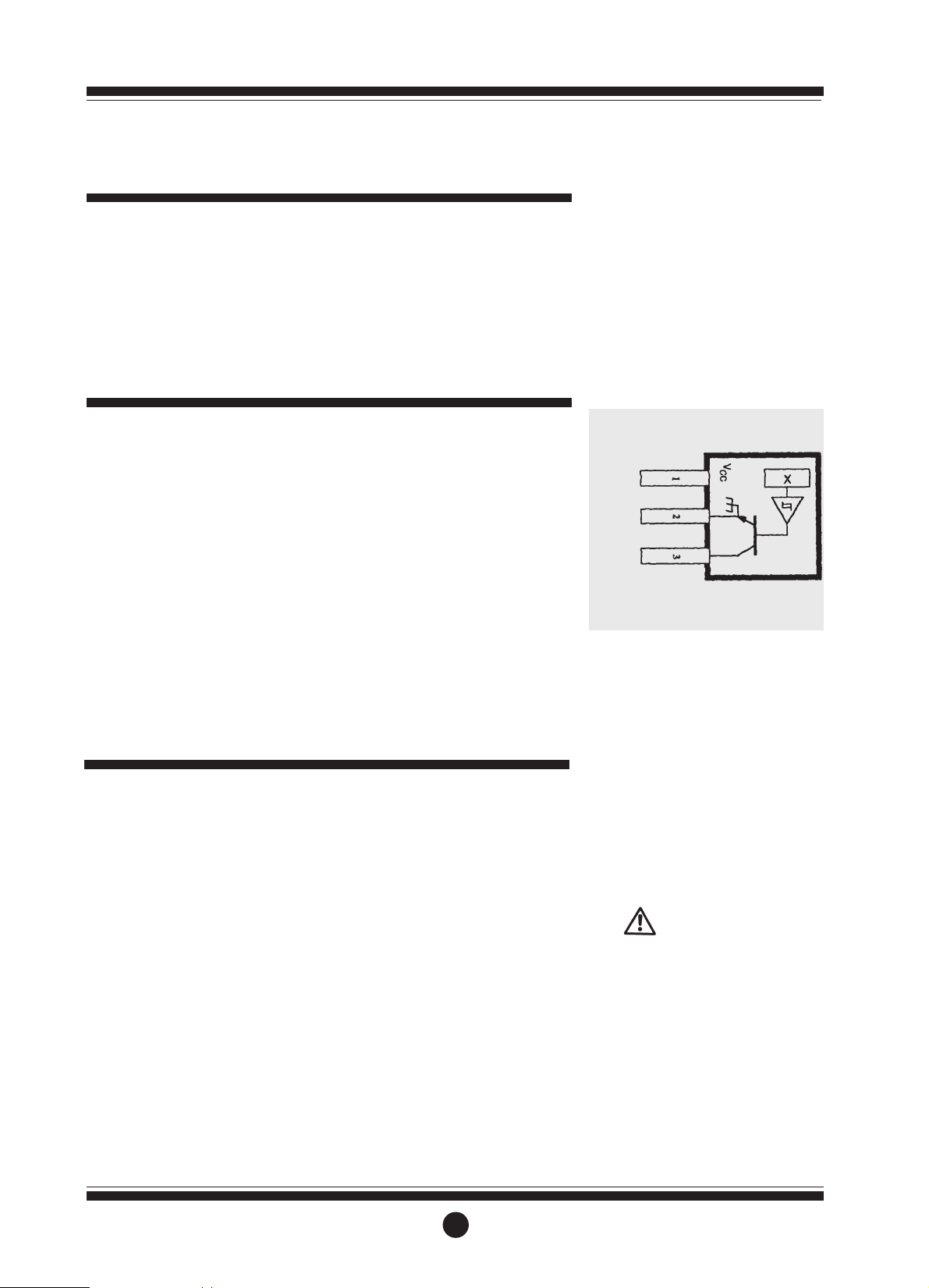
Pulser details
Hall Effect Sensor Wiring Details
Red - Supply
Green - Ground
Blue - Output
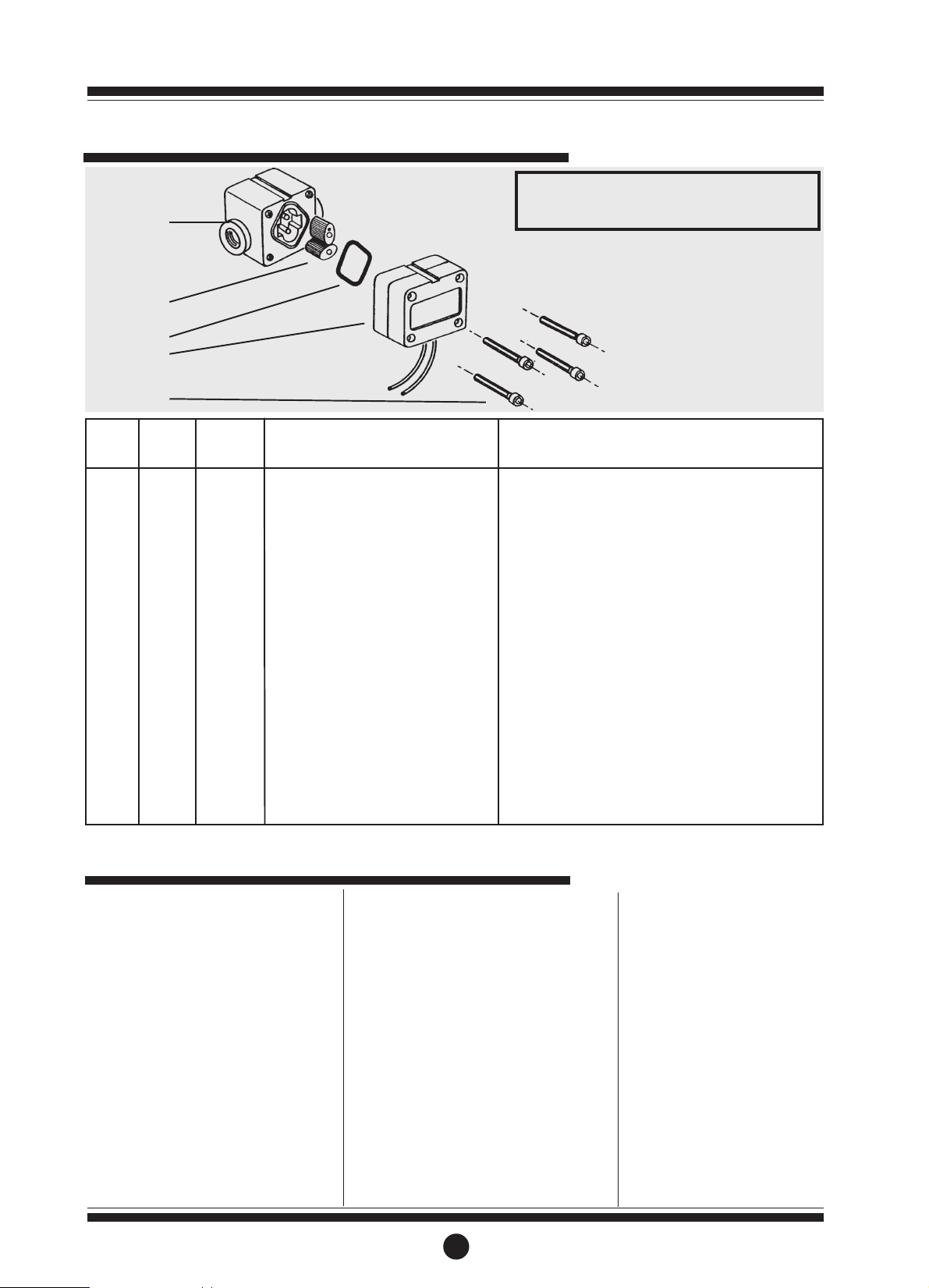
Disassembly:
1. Ensure the fluid supply to the meter
has been disconnected, and the
line pressure has been released
before disassembly.
2. Remove four (4) screws (Item 3) and
remove the meter body cover (Item
2).
3. Remove o-ring (Item 5) and inspect
(replace o-ring if damaged).
4. Remove rotors (Item 4), clean and
inspect (replace rotors if damaged).
Reassembly:
1. Place rotors (Item 4) into the meter
body. The rotors should be at 90
o
to each other.
Note: The rotor with magnets must be
placed in the body on the same side as
the groove on the body (refer to
diagram).
2. Lightly rotate the rotors (Item 4) by
hand (they must rotate freely).
3. Install o-ring (Item 5).
4. Replace the meter cap (Item 2).
Note: The groove on the cover must
line up with the groove on the meter
body (refer to diagram).
5. Replace four screws (Item 3).
CAUTION:
Care must be taken not to overtighten
the screws (Item 3) or damage may
occur.
Maintenance
Page 3

3
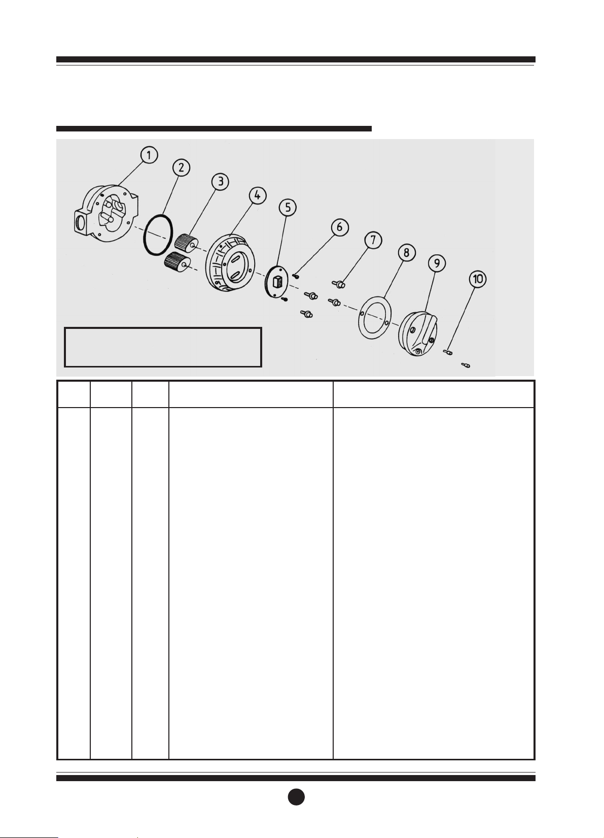
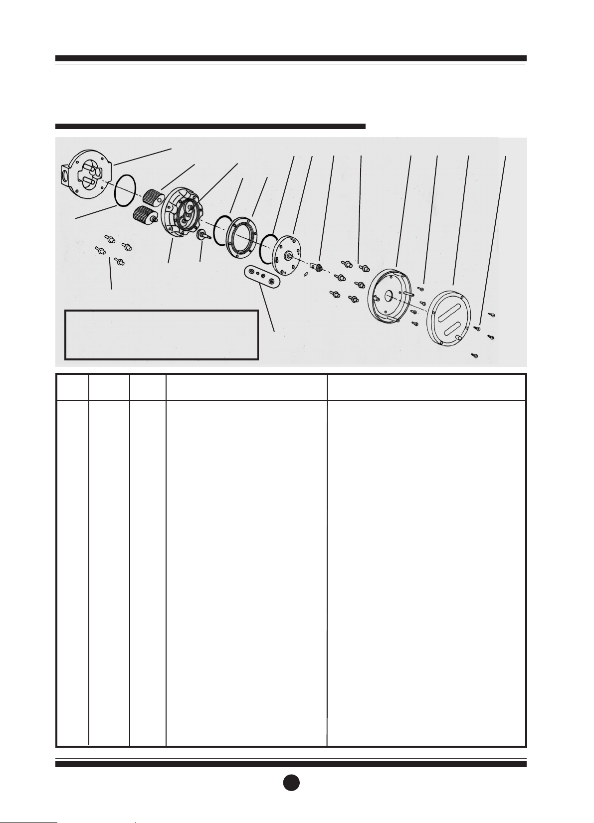
Display parts listing
1
2
3
4
5
Key:
u Indicates recommended Spare Parts to stock
Bold text indicates Stainless Steel Model Parts
1 1 MS600BS Meter Body Assy. (BSP) Stainless Steel
1 1 MS600NS Meter Body Assy. (NPT) Stainless Steel
1 1 MS605BS Meter Body Assy. (BSP) Aluminium
1 1 MS605NS Meter Body Assy. (NPT) Aluminium
21u MS3R-S Meter Cap Hall Effect Sensor Aluminium
21u MS3S-S Meter Cap Hall Effect Sensor Stainless Steel
21u MS3R-SR Meter Cap Reed Switch Aluminium
21u MS3S-SR Meter Cap Reed Switch Stainless Steel
34u MS98s Screws Aluminium
34
uu
MS113s Screws Stainless Steel
42
uu
MS601S Rotor Set Stainless Steel
51u BS127Vs O-ring (Viton)
51u BS127Ps O-ring (Perfluro Elastomer)
Item
No.
No.
Off.
Part or Set
(Order from this column only)
Part Description
Rec.
Parts
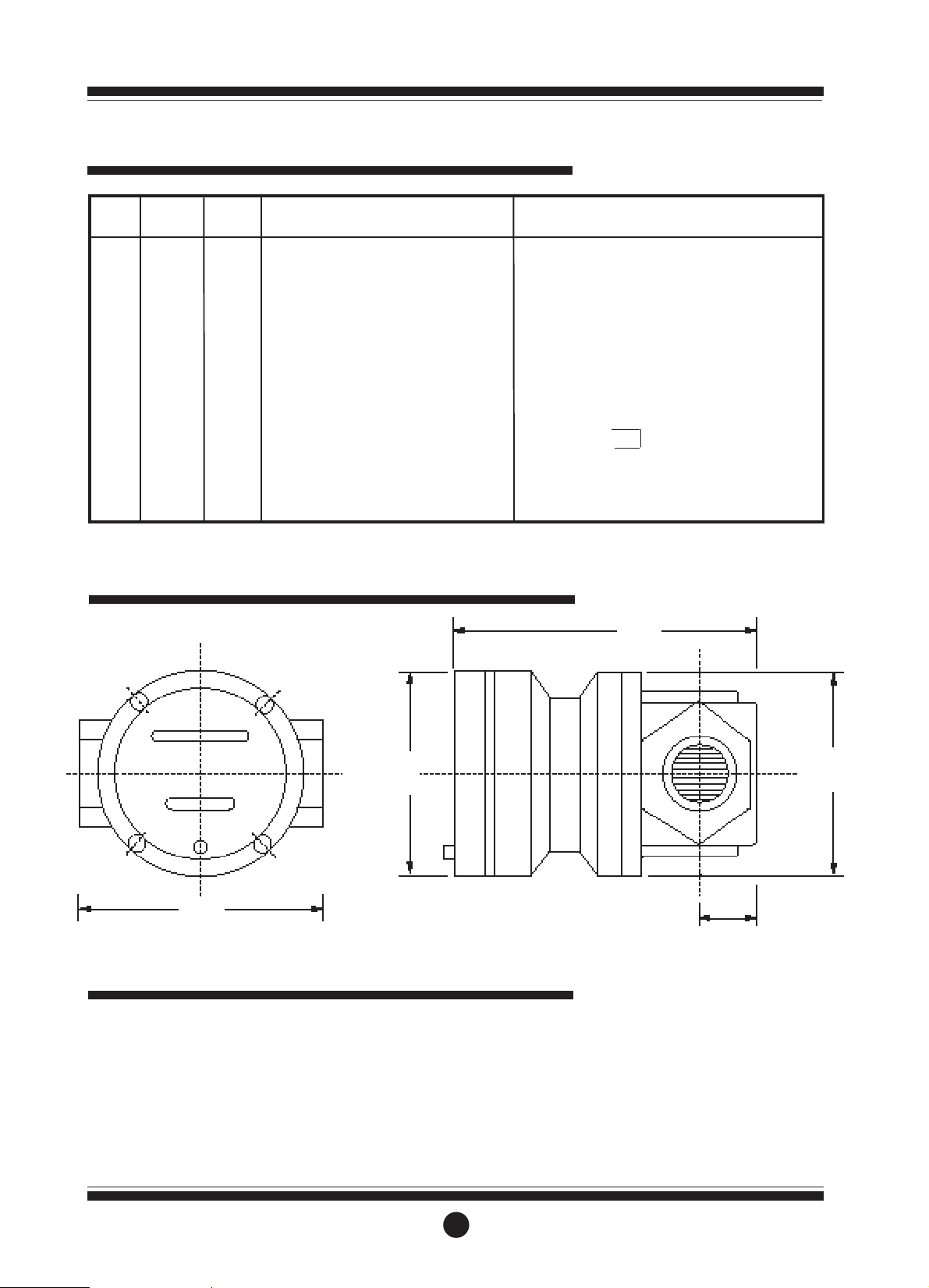
Meter specifications
Meter Type Stainless Steel Models Aluminium Models
Flow Ranges (Litres/hr or US Gall./hr)
Above 5 centipoise 0.5 to 50 / 0.132 to 13.2 0.5 to 50 / 0.132 to 13.2
Below 5 centipoise 2 to 50 / 0.528 to 13.2 2 to 50 / 0.528 to 13.2
Accuracy of Reading +/- 1% +/- 1%
Maximum Viscosity 1000 Centipoise 1000 Centipoise
Max. Operating Pressure 1000kPa/150PSI/10Bar 500kPa/75PSI/5Bar
Maximum Operating Temperature 120oC / 248oF80
o
C / 176oF
Pulse Type Hall Effect Sensor/Reed Switch Hall Effect Sensor/Reed Switch
Pulses per Litre/US Gallons 1547/5855.4 1547/5855.4
Meter Dimensions (Width x Height) 50x50mm / 1.97” x 1.97” 50x50mm / 1.97”x1.97”
Meter Dimensions Port Face to Face 67mm / 2.63” 60mm / 2.36”
Weight 602g / 21.23oz 308g / 10.86oz
Wetted Components 316 SS , Sapphire 6061 Alum., 316 SS, Sapphire
Page 4

Warranty
Trouble shooting
TROUBLE
Fluid will not flow through the meter
Reduced flow through the meter
Meter reading inaccurate
Meter not giving a pulse signal
TROUBLE SHOOTING GUIDE
CAUSE
A] Foreign matter blocking rotors
B] Line strainer blocked
C] Damaged rotors
D] Meter connections over tightened
A] Line stariner partially blocked
B] Fluid is too viscous
A] Fluid flowrate is too low or too high
B] Air in fluid
C] Excess wear caused by incorrect installation
A] Faulty hall effect sensor or reed switch
B] Faulty magnet
C] Rotors installed in wrong position
REMEDY
A] Dismantle meter, clean rotors (Strainer must
be fitted in line.
B] Clean strainer
C] Replace rotors (Strainer must be fitted in
line)
D] Re-adjust connections
A] Clean strainer
B] Maximum viscosity 1000 centipoise
A] See specifications for min. and max.
flowrates
B] Bleed air from system
C] Check meter body and rotors
A] Replace meter cap
B] Replace rotors
C] Refer to correct rotor positioning - assembly
instructions.
Great Plains Industries, Inc. Limited Warranaty Policy
Great Plains Industries, Inc., 5252 East 36th Street North, Wichita, Kansas USA 67220-3205, hereby provides a limited one year
warranty against defects in material and workmanship on all products manufactured by Great Plains Industries, Inc. This warranty
shall extend to the purchaser of this product and to any person to whom such product is transferred during the warranty period.
The warranty period shall begin on the date of the original new equipment purchase. Warrantor’s obligation hereunder shall be
limited to repairing defective workmanship or replacing or repairing any defective part or parts. This warranty shall not apply if:
a.)The product has been altered or modified outside the warrantor’s duly appointed
representative;
b.)The product has been subjected to neglect, misuse, abuse or damage or has been installed or operated other than in
accordance with the manufacturer’s operating instructions.
To make a claim against this warranty, notice of claim must be given in writing to the company at its address below no later than
30 days after the expiration of the warranty period. Such notice shall identify the defect in the product. The company shall, within
14 days of receipt of such notice, notify the customer to either send the product, transportation prepaid, to the company at its office
in Wichita, Kansas, or to a duly authorized service center. The company shall perform all obligations imposed on it by the terms of
this warranty within 60 days of receipt of the defective product.
GREAT PLAINS INDUSTRIES, INC. EXCLUDES LIABILITY UNDER THIS WARRANTY FOR DIRECT, INDIRECT, INCIDENTAL
AND CONSEQUENTIAL DAMAGES INCURRED IN THE USE OR LOSS OF USE IF THE PRODUCT WARRANTED
HEREUNDER.
The company herewith expressly disclaims any warranty of merchantability or fitness for any particular purpose other than for
which it was designed.
This warranty gives you specific rights and you may also have other rights which vary from U.S. state to U.S. state.
NOTE: In compliance with MAGNUSON MOSS CONSUMER WARRANTY ACT - Part 702
(governs the resale availability of the warranty terms).
Page 5

PLEASE READ THIS INFORMATION
CAREFULLY BEFORE USE!
Before use, confirm the fluid to be used
is compatible with the meter. Refer to
Industry fluid compatibility charts or
consult your local representative for
advice.
To prevent damage from dirt or foreign
matter it is recommended that a Y or
basket type 200 mesh strainer be
installed as close as possible to the inlet
side of the meter. Contact your local
representative for advice.
Note:
To prevent damage to the meter slowly
fill the system with fluid (this will
prevent damage caused by air purge).
Failure to do this could damage the
meter.
To reduce pressure build up turn off the
pump at the end of each day.
Positive displacement flowmeters
GM002 series instruction manual
To the owner
Operation
1
Please take a few minutes to read
through this manual before installing
and operating your meter. Always
retain this manual for future reference.
If you have any problems with the
meter, refer to the maintenance and
trouble shooting sections of this
manual.
This manual contains connection and
operating instructions for the GM002
Series meters. For models with display,
an additional manual is supplied. If you
need further assistance, contact your
local representative or distributor for
advice.
This Flowmeter has incorporated the
oval rotor principal into its design. This
has proven to be a reliable and highly
accurate method of measuring flow.
Exceptional repeatability and high
accuracy over a wide range of fluid
viscosities and flow rates are features of
the oval rotor design. With low pressure
drop and high pressure rating means
oval rotor flow meters are suitable for
both gravity and pump (in-line)
applications.
GM002 Series Flowmeters are available
in either PPS (Polyphenylene Sulfide)
Aluminium or 316 Stainless Steel.
Standard rotors are made from 316
Stainless Steel. Optional PPS rotors
with Hastalloy C Shafts available on
PPS models only.
MS16G
0603
0005
Page 6
1. Use thread sealant on all pipe
threads.
2. Ensure the meter is installed so that
rotor shafts are always in a
horizontal plane. Flow is bi-
directional.
3. GPI recommends use of flexible
connections.
4. Extreme care must be taken when
installing the meter. Pipe strain or
overtightening meter connections
can cause meter damage.
2
Installation
Hall Effect Sensor Specifications;
l 4.5V to 24V (4.6 ~ 9mA) operation
needs only an unregulated supply.
l Open collector 25mA output NPN
compatible with digital logic.
l Reverse battery protection.
l Temperature -40oC / -40oF ~
150oC / 300oF.
Reed Relay Specifications;
l Two wire SPST N/O.
l Switching voltage 150VDC
maximum current 0.25 AMPS.
l Rating 3 watts.
l Temperature -40oC / -40oF ~
150oC / 300oF.
Pulser details
Hall Effect Sensor Wiring Details
Red - Supply
Green - Ground
Blue - Output
Disassembly:
1. Ensure the fluid supply to the meter
has been disconnected, and the
line pressure has been released
before disassembly.
2. Remove four (4) screws (Item 3) and
remove the meter body cover (Item
2).
3. Remove o-ring (Item 5) and inspect
(replace o-ring if damaged).
4. Remove rotors (Item 4), clean and
inspect (replace rotors if damaged).
Reassembly:
1. Place rotors (Item 4) into the meter
body. The rotors should be at 90
o
to each other.
Note: The rotor with magnets must be
placed in the body on the same side as
the groove on the body (refer to
diagram).
2. Lightly rotate the rotors (Item 4) by
hand (they must rotate freely).
3. Install o-ring (Item 5).
4. Replace the meter cap (Item 2).
Note: The groove on the cover must
line up with the groove on the meter
body (refer to diagram).
5. Replace four screws (Item 3).
CAUTION:
Care must be taken not to overtighten
the screws (Item 3) or damage may
occur.
Maintenance
Page 7
3
Display parts listing
1
2
3
4
5
1 1 MS1R-1S Meter Body Assy. (BSP)
1 1 MS1R-1C Meter Body Assy. (BSP) Hastalloy C Shafts
1 1 MS1S-1S Meter Body Assy. (BSP) Stainless Steel
1 1 MS1R-2S Meter Body Assy. (NPT)
1 1 MS1R-2C Meter Body Assy. (NPT) Hastalloy C Shafts
1 1 MS1S-2S Meter Body Assy. (NPT) Stainless Steel
1 1 MS1AL-1S Meter Body Assy. (BSP) Aluminium
1 1 MS1AL-2S Meter Body Assy. (NPT) Aluminium
21u MS3R-S Meter Cap Hall Effect Sensor
21u MS3S-S Meter Cap Hall Effect Sensor Stainless Steel
21u MS3R-SR Meter Cap Reed Switch
21u MS3S-SR Meter Cap Reed Switch Stainless Steel
34u MS98s Screws
34
uu
MS113s Screws Stainless Steel
42u MS6s Rotor Set
42
uu
MS6-1s Rotor Set Stainless Steel
51u BS127Vs O-ring (Viton)
51u BS127Ps O-ring (Perfluro Elastomer)
Item
No.
No.
Off.
Part or Set
(Order from this column only)
Part Description
Rec.
Parts
Key:
u Indicates recommended Spare Parts to stock
Bold text indicates Stainless Steel Model Parts
Meter specifications
Meter Type SS & Ryton Models Aluminium Models
Flow Ranges (Litres/hr or US Gall./hr)
Above 5 centipoise 2 to 100 / 0.53 to 26.4 2 to 100 / 0.53 to 26.4
Below 5 centipoise 5 to 100 / 1.32 to 26.4 3 to 100 / 0.8 to 26.4
Accuracy of Reading +/- 1% +/- 1%
Maximum Viscosity 1000 Centipoise 1000 Centipoise
Max. Operating Pressure Ryton Models 500kPa/75PSI/5Bar 500kPa/75PSI/5Bar
SS Models 1000/kPa/150PSI/10Bar 80oC / 176oF
Maximum Operating Temp. Ryton Models 80oC / 176oF
SS Models 120oC / 240oF
Pulse Type Hall Effect Sensor/Reed Switch Hall Effect Sensor/Reed Switch
Pulses per Litre/US Gallons 1000/3785 1000/3785
Meter Dimensions (Width x Height) 50x50mm / 1.97” x 1.97” 50x50mm / 1.97”x1.97”
Meter Dimensions Port Face to Face 65mm / 2.58” 60mm / 2.36”
Weight Ryton Models 240g / 8.5oz 310g / 11oz
SS Models 600g / 21.2oz
Wetted Components SS Models 316 SS, Zirconia Bush 6061 Alum., 316 SS, Ryton
Ryton Models Ryton, 316 SS, Zirconia Bush, Hastalloy C Zirconia Bush
Page 8

Warranty
Trouble shooting
TROUBLE
Fluid will not flow through the meter
Reduced flow through the meter
Meter reading inaccurate
Meter not giving a pulse signal
TROUBLE SHOOTING GUIDE
CAUSE
A] Foreign matter blocking rotors
B] Line strainer blocked
C] Damaged rotors
D] Meter connections over tightened
A] Line stariner partially blocked
B] Fluid is too viscous
A] Fluid flowrate is too low or too high
B] Air in fluid
C] Excess wear caused by incorrect installation
A] Faulty hall effect sensor or reed switch
B] Faulty magnet
C] Rotors installed in wrong position
REMEDY
A] Dismantle meter, clean rotors (Strainer must
be fitted in line.
B] Clean strainer
C] Replace rotors (Strainer must be fitted in
line)
D] Re-adjust connections
A] Clean strainer
B] Maximum viscosity 1000 centipoise
A] See specifications for min. and max.
flowrates
B] Bleed air from system
C] Check meter body and rotors
A] Replace meter cap
B] Replace rotors
C] Refer to correct rotor positioning - assembly
instructions.
Great Plains Industries, Inc. Limited Warranaty Policy
Great Plains Industries, Inc., 5252 East 36th Street North, Wichita, Kansas USA 67220-3205, hereby provides a limited one year
warranty against defects in material and workmanship on all products manufactured by Great Plains Industries, Inc. This warranty
shall extend to the purchaser of this product and to any person to whom such product is transferred during the warranty period.
The warranty period shall begin on the date of the original new equipment purchase. Warrantor’s obligation hereunder shall be
limited to repairing defective workmanship or replacing or repairing any defective part or parts. This warranty shall not apply if:
a.)The product has been altered or modified outside the warrantor’s duly appointed
representative;
b.)The product has been subjected to neglect, misuse, abuse or damage or has been installed or operated other than in
accordance with the manufacturer’s operating instructions.
To make a claim against this warranty, notice of claim must be given in writing to the company at its address below no later than
30 days after the expiration of the warranty period. Such notice shall identify the defect in the product. The company shall, within
14 days of receipt of such notice, notify the customer to either send the product, transportation prepaid, to the company at its office
in Wichita, Kansas, or to a duly authorized service center. The company shall perform all obligations imposed on it by the terms of
this warranty within 60 days of receipt of the defective product.
GREAT PLAINS INDUSTRIES, INC. EXCLUDES LIABILITY UNDER THIS WARRANTY FOR DIRECT, INDIRECT, INCIDENTAL
AND CONSEQUENTIAL DAMAGES INCURRED IN THE USE OR LOSS OF USE IF THE PRODUCT WARRANTED
HEREUNDER.
The company herewith expressly disclaims any warranty of merchantability or fitness for any particular purpose other than for
which it was designed.
This warranty gives you specific rights and you may also have other rights which vary from U.S. state to U.S. state.
NOTE: In compliance with MAGNUSON MOSS CONSUMER WARRANTY ACT - Part 702
(governs the resale availability of the warranty terms).
Page 9
MS17G
0603
0008
Positive displacement flowmeters
GM003 series instruction manual
To the owner
Operation
1
Please take a few minutes to read
through this manual before installing
and operating your meter. Always
retain this manual for future reference.
If you have any problems with the
meter, refer to the maintenance and
trouble shooting sections of this
manual.
This manual contains connection and
operating instructions for the GM003
meters. For models with displays, an
additional manual is supplied. If you
need further assistance, contact your
local representative or distributor for
advice.
This Flowmeter has incorporated the
oval rotor principal into its design. This
has proven to be a reliable and highly
accurate method of measuring flow.
Exceptional repeatability and high
accuracy over a wide range of fluid
viscosities and flow rates are features of
the oval rotor design. With low pressure
drop and high pressure rating means
oval rotor flow meters are suitable for
both gravity and pump (in-line)
applications.
The GPI GM003 Series Flowmeters are
available in either PPS (Polyphenylene
Sulfide Resins),
Aluminium or 316 Stainless Steel.
Standard rotors are made from 316
Stainless Steel. Optional PPS rotors
with Hastalloy C Shafts available on
PPS models only.
PLEASE READ THIS INFORMATION
CAREFULLY BEFORE USE!
Before use, confirm the fluid to be used
is compatible with the meter. Refer to
Industry fluid compatibility charts or
consult your local representative for
advice.
To prevent damage from dirt or foreign
matter it is recommended that a Y or
basket type 200 mesh strainer be
installed as close as possible to the inlet
side of the meter. Contact your local
representative for advice.
Note:
To prevent damage to the meter slowly
fill the system with fluid (this will
prevent damage caused by air purge).
Failure to do this could damage the
meter.
To reduce pressure build up turn off the
pump at the end of each day.
Page 10
1. Use thread sealant on all pipe
threads.
2. Ensure the meter is installed so that
rotor shafts are always in a
horizontal plane. Flow is bi-
directional.
3. GPI recommends use of flexible
connections.
4. Extreme care must be taken when
installing the meter. Pipe strain or
overtightening meter connections
can cause meter damage.
2
Installation
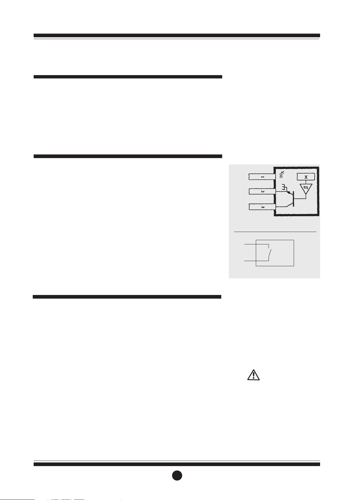
Hall Effect Sensor Specifications;
l 4.5V to 24V (4.6 ~ 9mA)
operation needs only an
unregulated supply.
l Open collector 25mA output
NPN (Current Sink) compatible
with digital logic.
l Reverse battery protection.
l Temperature -40oC / -40oF ~
150oC / 300oF.
Reed Relay Specifications;
l Two wire SPST N/O.
l Switching voltage 150VDC
maximum current 0.25 AMPS.
l Rating 3 watts.
l Temperature -40oC / -40oF ~
150oC / 300oF.
l Duty Cycle 20% on 80% off.
Pulser details
Hall Effect Sensor Wiring Details
Red - Supply
Green - Ground
Blue - Output
Disassembly:
1. Ensure the fluid supply to the meter
has been disconnected, and the
line pressure has been released
before disassembly.
2. Remove four (4) screws (Item 3) and
remove the meter body cover (Item
2).
3. Remove o-ring (Item 5) and inspect
(replace o-ring if damaged).
4. Remove rotors (Item 4), clean and
inspect (replace rotors if damaged).
Reassembly:
1. Place rotors (Item 4) into the meter
body. The rotors should be at 90o
to each other.
Note: The rotor with magnets must be
placed in the body on the same side as
the groove on the body (refer to
diagram).
2. Lightly rotate the rotors (Item 4) by
hand (they must rotate freely).
3. Install o-ring (Item 5).
4. Replace the meter cap (Item 2).
Note: The groove on the cover must
line up with the groove on the meter
body (refer to diagram).
5. Replace four screws (Item 3).
CAUTION:
Care must be taken not to overtighten
the screws (Item 3) or damage may
occur.
Maintenance
1
2
Reed Switch Wiring Details
Page 11

1 1 MS2R-1S Meter Body Assy. (BSP)
1 1 MS2R-1C Meter Body Assy. (BSP) Hastalloy C Shafts
1 1 MS2S-1S Meter Body Assy. (BSP) Stainless Steel
1 1 MS2R-2S Meter Body Assy. (NPT)
1 1 MS2R-2C Meter Body Assy. (NPT) Hastalloy C Shafts
1 1 MS2S-2S Meter Body Assy. (NPT) Stainless Steel
1 1 MS2AL-1S Meter Body Assy. (BSP) Aluminium
1 1 MS2AL-2S Meter Body Assy. (NPT) Aluminium
21u MS3R-S Meter Cap Hall Effect Sensor
21u MS3S-S Meter Cap Hall Effect Sensor Stainless Steel
21u MS3R-SR Meter Cap Reed Switch (Ryton & Alumin. Models)
21u MS3S-SR Meter Cap Reed Switch Stainless Steel
34u MS98s Screws (Ryton & Alumin. Models)
34
uu
MS113s Screws Stainless Steel
4 2 u MS7-1Es Rotor SS Hall (Set)
4 2 u MS7-1HEs Rotor SS High Viscosity Hall (Set)
42
uu
MS7-1Rs Rotor SS Reed (Set)
42
uu
MS7-1HRs Rotor SS Reed High Viscosity (Set)
42u MS7Rs Rotor PPS Reed (Set)
42u MS7Es Rotor PPS Hall (Set)
51u BS127Vs O-ring (Viton)
51u BS127Ps O-ring (Perfluro Elastomer)
3
Display parts listing
1
2
3
4
5
Item
No.
No.
Off.
Part or Set
(Order from this column only)
Part DescriptionRec.
Parts
Key:
u Indicates recommended Spare Parts to stock
Bold text indicates Stainless Steel Model Parts
Meter specifications
Meter Type SS & Ryton Models Aluminium Models
Flow Ranges (Litres/hr or US Gall./hr)
Above 5 centipoise 15 to 500 / 4 to 132 15 to 500 / 4 to 132
Below 5 centipoise 25 to 500 / 6 to 132 25 to 500 / 6 to 132
Accuracy of Reading +/- 1% +/- 1%
Maximum Viscosity 1000 Centipoise 1000 Centipoise
Max. Operating Pressure Ryton Models 500kPa/75PSI/5Bar 500kPa/75PSI/5Bar
SS Models 1000/kPa/150PSI/10Bar
Max. Operating Temp. Ryton Models 80oC / 176oF80
o
C / 176oF
SS Models 120oC / 248oF
Pulse Type Hall Effect Sensor/Reed Switch Hall Effect Sensor/Reed Switch
Pulses per Litre/US Gallons 400/1514 400/1514
Meter Dimensions (Width x Height) 50x50mm / 1.97” x 1.97” 50x50mm / 1.97”x1.97”
Meter Dimensions Port Face to Face 65mm / 2.58” 60mm / 2.36”
Weight SS 600g / 21.2oz Ryton 240g / 8.5oz 320g / 12oz
Wetted Components SS Models 316 SS, Zirconia Bush 6061 Alum., 316 SS, Ryton
Ryton Models Ryton, 316 SS, Zirconia Bush, Hastalloy C Zirconia Bush
Page 12

Warranty
Trouble shooting
TROUBLE
Fluid will not flow through the meter
Reduced flow through the meter
Meter reading inaccurate
Meter not giving a pulse signal
TROUBLE SHOOTING GUIDE
CAUSE
A] Foreign matter blocking rotors
B] Line strainer blocked
C] Damaged rotors
D] Meter connections over tightened
A] Line stariner partially blocked
B] Fluid is too viscous
A] Fluid flowrate is too low or too high
B] Air in fluid
C] Excess wear caused by incorrect installation
A] Faulty hall effect sensor or reed switch
B] Faulty magnet
C] Rotors installed in wrong position
REMEDY
A] Dismantle meter, clean rotors (Strainer must
be fitted in line.
B] Clean strainer
C] Replace rotors (Strainer must be fitted in
line)
D] Re-adjust connections
A] Clean strainer
B] Maximum viscosity 1000 centipoise
A] See specifications for min. and max.
flowrates
B] Bleed air from system
C] Check meter body and rotors
A] Replace meter cap
B] Replace rotors
C] Refer to correct rotor positioning - assembly
instructions.
Great Plains Industries, Inc. Limited Warranaty Policy
Great Plains Industries, Inc., 5252 East 36th Street North, Wichita, Kansas USA 67220-3205, hereby provides a limited one year
warranty against defects in material and workmanship on all products manufactured by Great Plains Industries, Inc. This warranty
shall extend to the purchaser of this product and to any person to whom such product is transferred during the warranty period.
The warranty period shall begin on the date of the original new equipment purchase. Warrantor’s obligation hereunder shall be
limited to repairing defective workmanship or replacing or repairing any defective part or parts. This warranty shall not apply if:
a.)The product has been altered or modified outside the warrantor’s duly appointed
representative;
b.)The product has been subjected to neglect, misuse, abuse or damage or has been installed or operated other than in
accordance with the manufacturer’s operating instructions.
To make a claim against this warranty, notice of claim must be given in writing to the company at its address below no later than
30 days after the expiration of the warranty period. Such notice shall identify the defect in the product. The company shall, within
14 days of receipt of such notice, notify the customer to either send the product, transportation prepaid, to the company at its office
in Wichita, Kansas, or to a duly authorized service center. The company shall perform all obligations imposed on it by the terms of
this warranty within 60 days of receipt of the defective product.
GREAT PLAINS INDUSTRIES, INC. EXCLUDES LIABILITY UNDER THIS WARRANTY FOR DIRECT, INDIRECT, INCIDENTAL
AND CONSEQUENTIAL DAMAGES INCURRED IN THE USE OR LOSS OF USE IF THE PRODUCT WARRANTED
HEREUNDER.
The company herewith expressly disclaims any warranty of merchantability or fitness for any particular purpose other than for
which it was designed.
This warranty gives you specific rights and you may also have other rights which vary from U.S. state to U.S. state.
NOTE: In compliance with MAGNUSON MOSS CONSUMER WARRANTY ACT - Part 702
(governs the resale availability of the warranty terms).
Page 13
MS345G
0603
0005
Positive Displacement Flowmeters
GM005 series instruction manual
GM005 Pulse Meter From serial No. CXXXX
Page 14
PLEASE READ THIS INFORMATION
CAREFULLY BEFORE USE!
Before use, confirm the fluid to be used
is compatible with the meter. Refer to
industry fluid compatibility charts or
consult your local representative for
advice.
To prevent damage from dirt or foreign
matter it is recommended that a Y or
Basket type 60 mesh strainer be
installed as close as possible to the
inlet side of the meter. Contact your
local representative for advice.
Note: When a strainer is installed it
should be regularly inspected and
cleaned. Failure to keep the strainer
clean will dramatically effect flow
meter performance.
Note: To prevent damage caused by air
purge slowly fill the meter with fluid.
To reduce pressure build up turn off the
pump at the end of each day.
Maintenance can be carried out to the
liquid crystal displays and pulse units
without removing or isolating the meter
from the line. When maintenance to
any other part of the meter is required,
the meter must be isolated and the line
pressure reduced.
The reed switch pulse unit can cause
inaccurate rate counts when used with
high speed counters. It is advised that a
debounce circuit be used. Contact your
meter distributor for further
information.
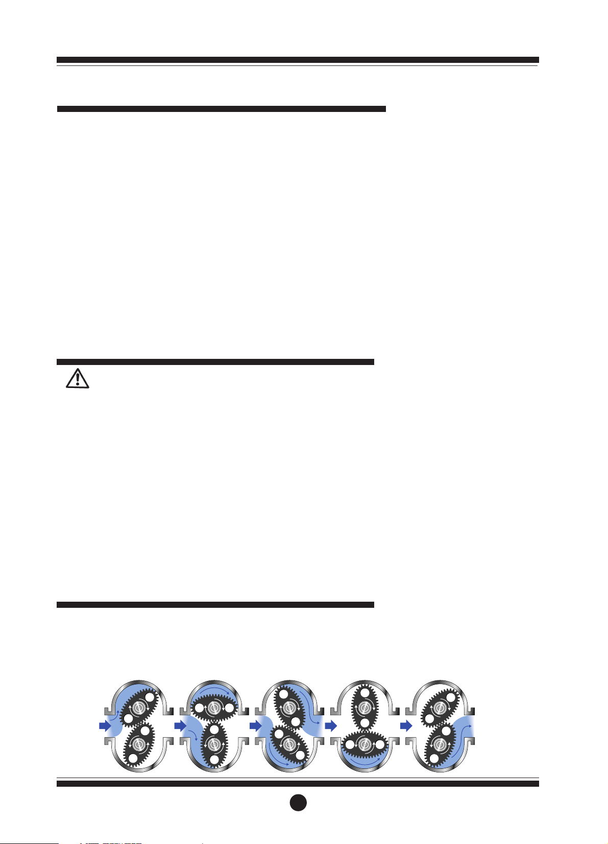
When fluid passes through the meter
the rotors turn, as shown below. The
magnets which are located in the rotors
will pass across the pulser circuit board
(containing either Reed switches or
Hall Effect sensors). A signal is
generated which is then sent by the
Pulse Circuit Board (PCB) to the
relevant LC display or receiving
instrument.
Operating Principle
Please take a few minutes to read
through this manual before installing
and operating your meter. Always
retain this manual for future reference.
If you have any problems with the
meter, refer to the maintenance and
trouble shooting sections of this
manual.
This manual contains connection and
operating instructions for the GM005
Series meters with Pulse outputs. For
models with an Liquid Crystal Display
an additional instruction manual is
supplied. If you need further assistance,
contact your local representative or
distributor for advice.
This Flow Meter has incorporated the
oval rotor principal into its design. This
has proven to be a reliable and highly
accurate method of measuring flow.
Exceptional repeatability and high
accuracy over a wide range of fluid
viscosities and flow rates are features of
the oval rotor design. With low
pressure drop and high pressure rating
oval rotor flow meters are suitable for
both gravity and pump (in line)
applications.
Flow meters are available in either
Aluminium or 316 Stainless Steel.
Standard rotors are made from PPS
(Polyphenylene Sulfide Resins) with
optional 316 Stainless Steel rotors
available for both Stainless steel and
Aluminium models.
GM005 Series Meters are available
with either;
* Pulse output
* Standard LC Display and Pulse
1
To the owner
Important Information
Page 15
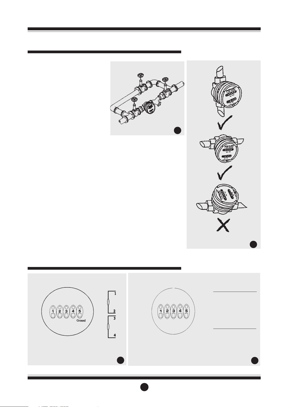
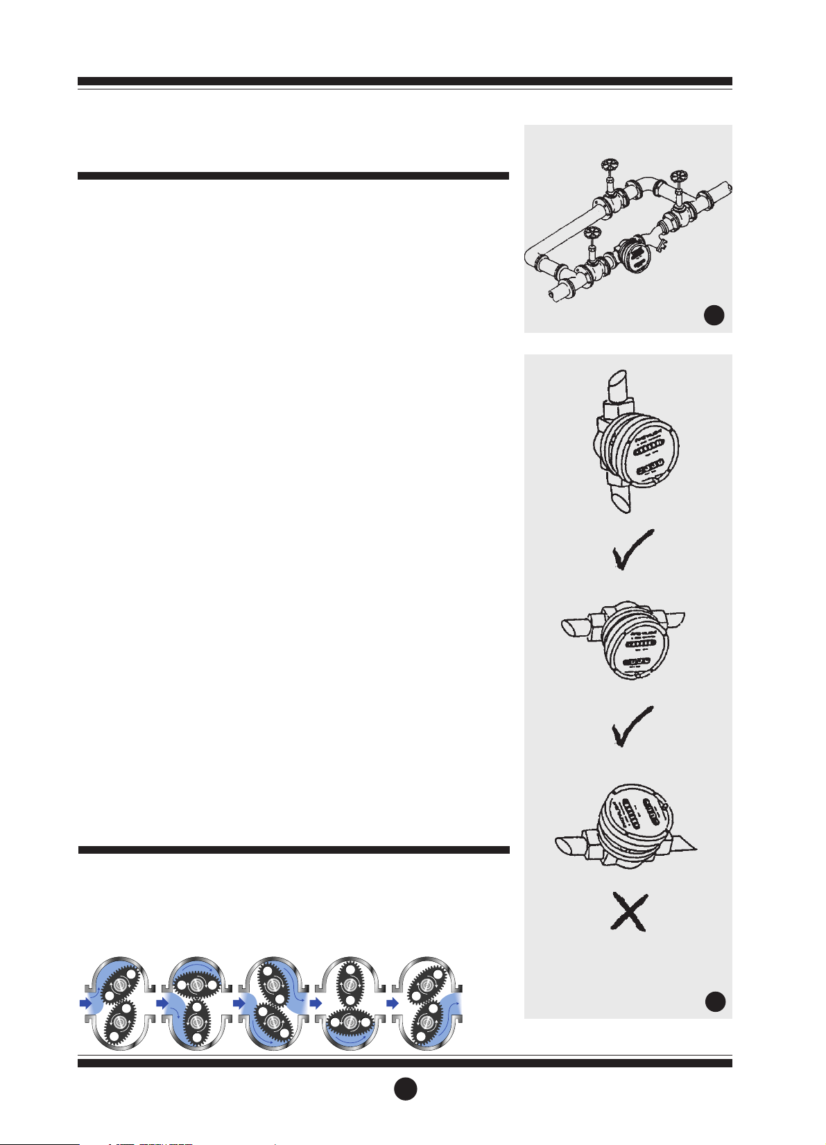
1] it is recommended that when setting
up pipework for meter installations a
bypass line be included in the design.
This provides the facility for a meter
to be removed for maintenace
without interrupting production. (See
Fig.1)
2] Use thread sealant on all pipe
threads.
3] For pump applications ensure pipe
work has the appropriate working
pressure rating to match the pressure
output of the pump. See Meter
Specifications section for further
details.
4] Install a wire mesh strainer (Y or
basket type 60 mesh as close as
possible to the inlet side of the meter.
5] Ensure that the meter is installed so
that the flow of the liquid is in the
direction of the arrows embossed on
the meter body.
6] The meter can be installed in any
orientation as long as the meter shafts
are in a horizontal plane. (Refer to
Fig.2 for correct installation) The
register assembly may be orientated
to suit the individual installation.
Note: Incorrect installation can cause
premature wear of meter components.
7] Do not over tighten meter
connections.
8] It is important that after initial
installation you fill the line slowly,
high speed air purge could cause
damage to the rotors.
9] Test the system for leaks.
10] Check the strainer for swarf or
foreign material, after the first 200
litres check periodically,
particularly if the flow rate
decreases.
2
Installation
1
2
Bypass Line
Flow Outlet
Flow Inlet
Strainer
Do Not Install Meter This Way
Electrical Connections
Contact rating 15VA
Maximum Voltage 150VDC
Note: Double rate pulse output not available
3
4
Reed/Hall combination
1 - Reed Switch
2 - Reed Switch
3 - HE Common 4 - HE Signal
5 - HE Supply +
Hall/Hall Combination
1 - HE1 Supply +
2 - HE1 Signal
3 - HE Common 4 - HE2 Signal
5 - HE Ground
Hall Effect Voltage 4.5 to 24 VDC
Current Draw Minimum 4.6mA
Output NPN Open Collector 25mA
Reed Switch Connections
Hall Effect or Reed/Hall Sensor Connections
Page 16

Disassembly
Ensure that the fluid supply to the
meter is disconnected, and the line
pressure is released before
disassembly, with the exception for
repair or maintenance to the LC
Display or PCB where there is no
necessity to isolate the meter from flow.
Refer to the exploded parts diagram on
subsequent pages for item numbers.
1a] Pulse Caps models: Undo the
conduit connector, remove pulse
cap (item 9) and remove the wires
from the pulse terminal board (item 5).
1b] Standard LC Display: Mark the
display orientation with a marking
pen, unscrew the four large screws
(Item 26) on top of the LC Display.
Carefully separate the LC Display
from the plastic housing and
disconnect the wires from the
pulse terminal block. (Refer to
additional Standard LC Display
instruction manual).
2] Remove the mounting adaptor plate
and gasket (Item 14).
3] Loosen the cap head screws (Item 7)
that hold down the meter cap (Item
4), remove the screws, washers and
lift off the cap.
4] Remove the o’ring (Item 2) from the o’ring
groove in the meter cap (Item 4).
5] Remove rotors (Item 3).
Reassembly
1] Before reassembling check the
condition of the rotors (replace if
necessary).
2] Check that the smooth side of the
rotors (not the plug side) is facing
you when inserting the rotors, the
smooth side of the rotor is the
magnet side. There is no difference
between rotor one or rotor two.
3] Replace the rotors (Item 3) onto the
shafts at 90oto each other (refer Fig.
5) and check their operation by
turning either of the rotors. If the
rotors are not in mesh correctly or
do not move freely, remove one of
the rotors and replace correctly at
90oto the other rotor. Re-check the
operation of the rotors.
4] Replace the o’ring (Item 2) into
groove in the meter cap, if the o’ring
has grown or is damaged in any way
replace it with a new part.
5] Replace the meter cap making sure
that the locating pin in the body
lines up with the hole in the meter
cap. Insert the cap head screws
(Item 7) and tighten in a diagonal
sequence 1, 3, 2, 4, etc.
6] The replacement of cables and
connectors are a reversal of the
disassembly procedure, replace
conduit fitting if required. When
replaceing the Standard LC Display,
confirm the orientation marks made
on disassembly are aligned then
screw the register into place.
7] Test the meter by turning the rotors
with a finger or by applying very low
air pressure (no more than a good
breath) to one end of the meter,
before returning the meter to the line.
Pulse Circuit Board (PCB) Notes:
The pulse PCB (Item 5) is fitted with (A)
two reed switches; (B) hall effect
sensors; or (C) one reed switch and one
hall effect sensor. The PCB board is
fastened to the meter cap (Item 4) by
two screws and stand off’s. All care and
caution should be taken when
removing or handling the PCB as both
the reed switch and hall effect sensor
are fragile.
Reed switch or hall effect sensors are
not available as individual replacement
parts and are only available with the
complete PCB (Item 5).
3
Service Instructions
5
Rotors must be at 90oto each other.
Rotor #2
Rotor #1
Page 17
4
Meter Parts Listing
1 1 MS298B Meter Body 1/2” BSP (Aluminium)
1 1 MS298N Meter Body 1/2” NPT (Aluminium)
1 1 MS337B Meter Body 1/2” BSP (Stainless Steel)
1 1 MS337N Meter Body 1/2” NPT (Stainless Steel)
21u BS145S “O” Ring (NBR)
21u BS145TES “O” Ring (Teflon)
21u BS145VS “O” Ring (Viton)
32u MS342S Rotors PPS (Polyphenylene Sulfide Resins)
32
uu
MS342-1S Rotors (Stainless Steel)
32u MS342HS High Viscosity Rotors (PPS)
32u MS342-1HS High Viscosity Rotors (Stainless Steel)
4 1 MS297 Meter Cap (Aluminium)
4 1 MS338 Meter Cap (Stainless Steel)
51u MS344-RS PCB (Standard Reed Switch)
51u MS344-HES PCB (Hall Effect Sensor)
5 1 MS344-R/HES PCB ( 1 Reed Switch & 1 Hall Effect Sensor)
6 2 MS284S PCB Board Screws
74u MS346S Meter Cap Screws (Standard)
74u MS350S Meter Cap Screws (Stainless Steel)
81u MS340S Pulser Cap Gasket
9 1 MS296 Pulser Cap (Aluminium) 20mm Conduit Thread
9 1 MS296N Pulser Cap (Aluminum) 1/2” NPT Thread
9 1 MS339 Pulser Cap (Stainless Steel) 20mm Conduit Thread
9 1 MS339N Pulser Cap (Stainless Steel) 1/2” NPT Thread
10 2 MS347S Pulser Cap Screw (Stainless Steel)
11 1 MS37 Warning Label (Not Shown)
13 1 Customer to Specify Legend Plate (Not Shown) inc. Hammer Screws
Item
No.
No.
Off.
Part or Set
(Order from this column only)
Part Description
Key:
u Indicates recommended Spare Parts to stock
Bold text indicates Stainless Steel Model Parts
Rec.
Parts
Page 18

Pulse
1 to 30/ 0.26 to 8
3 to 25/ 0.8 to 6.60
+/- 0.5%
1000 Centipoise
5500kPa/ 800 PSI/ 55 BAR
80°C/ 176°F
(S.S. Models 120°C/ 248°F)
Dual Reed Switches or Hall
Effect Sensor or combination
HE Sensor/Reed Switch**
112 / 224
* Unless High Viscosity Rotors are fitted.
5
Meter Specifications
Meter Type
Flow Ranges
Litres/minute - US Gall/min
Above 5 Centipoise
Below 5 Centipoise
Accuracy of Reading
Maximum Viscosity*
Max. Operating Pressure
Max. Operating Temp.
Pulse Type
Pulses Per Litre/US Gallon
Meter Trouble Shooting
TROUBLE
Fluid will not flow through meter
Reduced flow through the meter
Meter reading inaccurate
Meter not giving a pulse signal
CAUSE
a] Foreign matter blocking rotors
b] Line strainer blocked
c] Damaged rotors
d] Meter connections over tightened
e] Fluid is too viscous
a] Strainer is partially blocked
b] Fluid is too viscous
a] Fluid flow rate is too high or too low
b] Fluid is too viscous
c] Excess wear caused by incorrect
installation
a] Faulty hall effect sensor
b] Faulty reed switch
c] Magnets failed
REMEDY
a] Dismantle meter, clean rotors
(Strainer must be fitted in line)
b] Clean strainer
c] Replace rotors (Strainer must be
fitted in line)
d] Re-adjust connections
e] See specifications for maximum
viscosity
a] Clean strainer
b] See specifications for maximum
viscosity
a] See specifications for minimum and
maximum flow rates
b] Bleed air from system
c] Check meter body and rotors.
Replace as required. Refer to
installation instructions
a] Replace PCB Board
b] Replace PCB Board
c] Replace magnets
Page 19

Warranty
Meter Dimensions
96mm
70mm
100mm
105mm
18mm
20mm
Pulse Meter Dimensions
Great Plains Industries, Inc. Limited Warranty Policy
Great Plains Industries, Inc., 5252 East 36th Street North, Wichita, Kansas USA 67220-3205, hereby provides a limited one year warranty against defects in material and
workmanship on all products manufactured by Great Plains Industries, Inc. This warranty shall extend to the purchaser of this product and to any person to whom such
product is transferred during the warranty period.
The warranty period shall begin on the date of the original new equipment purchase. Warrantor’s obligation hereunder shall be limited to repairing defective workmanship or
replacing or repairing any defective part or parts. This warranty shall not apply if:
a.)The product has been altered or modified outside the warrantor’s duly appointed representative;
b.)The product has been subjected to neglect, misuse, abuse or damage or has been installed or operated other than in accordance with the manufacturer’s operating
instructions.
To make a claim against this warranty, notice of claim must be given in writing to the company at its address below no later than 30 days after the expiration of the warranty
period. Such notice shall identify the defect in the product. The company shall, within 14 days of receipt of such notice, notify the customer to either send the product,
transportation prepaid, to the company at its office in Wichita, Kansas, or to a duly authorized service center. The company shall perform all obligations imposed on it by the
terms of this warranty within 60 days of receipt of the defective product.
GREAT PLAINS INDUSTRIES, INC. EXCLUDES LIABILITY UNDER THIS WARRANTY FOR DIRECT, INDIRECT, INCIDENTAL AND CONSEQUENTIAL DAMAGES
INCURRED IN THE USE OR LOSS OF USE IF THE PRODUCT WARRANTED HEREUNDER.
The company herewith expressly disclaims any warranty of merchantability or fitness for any particular purpose other than for which it was designed.
This warranty gives you specific rights and you may also have other rights which vary from U.S. state to U.S. state.
NOTE: In compliance with MAGNUSON MOSS CONSUMER WARRANTY ACT - Part 702
(governs the resale availability of the warranty terms).
Page 20
MS489G
0703
0004
Positive Displacement Flowmeters
GM505 series instruction manual
GM505 Mechanical meter • From serial No. CXXXX
Page 21
Thank you for purchasing a GPI GM
Series Flow Meter. Please take a few
minutes to read thorugh this manual
before installing and operating your
meter. If you have any problems with
the meter, refer to the maintenance and
trouble shooting sections of this
manual.
This manual contains connection and
operating instructions for the GM505
Series meters with mechanical
displays. If you need further assistance,
contact your local GPI representative
or contact GPI by telephone or fax for
advice.
The GPI GM Series Flow Meter has
incorporated the oval rotor principal
into its design. This has proven to be a
reliable and highly accurate method of
measuring flow. Exceptional
repeatability and high accuracy over a
wide range of fluid viscosities and flow
rates are features of the GM Series flow
meter design. The low pressure drop
and high pressure rating means the GM
Series flow meter is suitable forboth
gravity and pump (in line) applications.
The GPI GM Series flow meters are
available in either aluminium or 316
stainless steel. Standard rotors are
made from PPS.
The GM505 Series mechanical
displays have a resettable batch
totaliser and non-resettable
accumulative totaliser.
PLEASE READ THIS INFORMATION
CAREFULLY BEFORE USE!
Before use, confirm the fluid to be used
is compatible with the meter (refer to
the GPI fluid compatibility chart), or
consult your local GPI representative
for advice.
To prevent damage from dirt or foreign
matter, GPI recommends a Y or Basket
type 60 mesh strainer be installed as
close as possible to the inlet side of the
meter (if required contact GPI for
further information).
Note: When a strainer is installed it
should be regularly inspected and
cleaned. Failure to keep the strainer
clean will dramatically effect flow
meter performance.
To prevent damage to the meter slowly
fill the system with fluid (this will
prevent damage caused by air purge).
Note: Failure to do this could damage
the meter.
For pump applications, turn off the
pump at the end of each day.
1
To the owner
Important Information
Page 22
1] GPI recommends that when setting
up pipework for meter installations a
bypass line be included in the
design. This provides the facility for
a meter to be removed for
maintenace without interrupting
production. (See Fig.1)
2] Use thread sealant on all pipe
threads.
3] For pump applications ensure pipe
work has the appropriate working
pressure rating to match the pressure
output of the pump.
4] Install a wire mesh strainer (Y or
basket type 60 mesh as close as
possible to the inlet side of the meter.
5] Ensure that the meter is installed so
that the flow of the liquid is in the
direction of the arrows embossed on
the meter body.
6] The meter can be installed in any
orientation as long as the meter
shafts are in a horizontal plane.
(Refer to Fig.2 for correct
installation) The register assembly
may be orientated to suit the
individual installation.
Note: Incorrect installation can cause
premature wear of meter components.
7] Do not over tighten meter connections.
8] It is important that after initial
installation you fill the line slowly,
high speed air purge could cause
damage to the rotors.
9] Test the system for leaks.
10] Check the strainer for swarf or
foreign material, after the first 200
litres check periodically,
particularly if the flow rate
decreases.
2
Installation
When fluid passes through the meter,
rotors turn. The gear located on top of
one of the rotors drives the mechanical
registers gear train which provides an
accurate readout.
Operation
1
2
Bypass Line
Flow Outlet
Flow Inlet
Strainer
Do Not Install Meter This Way
Page 23

Disassembly
Ensure that the fluid supply to the meter
is disconnected, and the line pressure
is released before disassembly. Refer to
the exploded parts diagram on page 5
for item numbers.
1] Remove the four screws (Item 17)
located on the face of the register.
Then remove the face plate cover
including register assembly.
2] Remove the four register mounting
screws (Item 15). Then remove the
lower half of the register housing.
3] Remove the six cover plate screws
(Item 12) and remove the cover
plate (Item 11).
4] Remove the four meter cap screws (Item
5) and remove the meter cap (Item 4).
5] Remove rotors (Item 3).
Reassembly
1] Clean all components before
reassembly.
2] Before reassembly check the
condition of the rotors (Item 3).
Replace if necessary.
3] Replace the rotor (with the gear) on
the short shaft in the housing then
place the 2nd rotor onto the shaft
so as the rotors are at 90° to each
other. (Refer Fig 3). Check rotor
operation by turning either of the
rotors. If the rotors are not in mesh
correctly or do not move freely
remove one of the rotors and
replace it correctly at 90° to the
other rotor. Recheck the operation
of the rotors.
4] Inspect the gears (Item 6) in the
meter cap (Item 4) for wear.
(Replace if required, refer to spare
parts on page 5 & 6).
5] Replace the o-ring (Item 2) into the
groove in the meter cap, if the o-
ring has been distorted or is
damaged in any way replace it with
a new part.
6] Replace the meter cap, making sure
the meter cap and the gear on the
rotor meshes correctly with the gear
in the meter cap (Item 4). Insert the
allen screws (Item 5) and tighten in
the sequence 1, 4, 2, & 3.
7] Inspect the bevel gear (Item 13), o-
ring (Item 10), and output gear (Item
7) for wear or damage. (Replace
faulty components if necessary).
8] Replacement of output shaft, bush
and seal.
Disassembly of output shaft
a.Remove the bevel gear.
b.Remove the circlip and push out
the output shaft assembly, including
washer.
c.Remove the seal.
d.Carefully press out the output shaft
bush (If required).
Assembly of output shaft
a.Carefully press the new output
shaft bush into place (Use Loctite
Primer 7471, as per instructions,
followed by sealant Loctite 262).
b.Insert a new seal into the groove of
the output shaft bush.
c.Replace the output gear and
washer and replace the circlip to
lock the output gear shaft into place.
d.Replace the bevel gear (Item 13)
and tighten the grub screw onto flat
face of shaft.
9] Place the o-ring (Item 10) into the
groove in the meter cap (Replace the
o-ring seal if required).
10] Place the cover plate onto the meter.
Replace the cover plate screws and
tighten the six cap head screws (Item
12) firmly.
11] Place the lower cover plate of the
register into position. Replace the
four screws (Item 15) and tighten.
12] Position the register correctly on top
of the lower register cover. Replace
the four screws (Item 17) and
tighten.
13] Test the meter by turning the rotors
with a finger or by applying low air
pressure (No more than a good
breath) to one end of the meter,
before returning meter to the line.
3
Service Instructions
5
Rotors must be at 90oto each other.
Rotor #2
Rotor #1
Page 24

4
Meter Trouble Shooting
TROUBLE SHOOTING GUIDE
TROUBLE
Fluid will not flow through meter
Reduced flow through the meter
Meter reading inaccurate
Fluid flows but no reading on meter
Fluid leaks into register
CAUSE
a] Foreign matter blocking rotors
b] Line strainer blocked
c] Damaged rotors
d] Meter connections over tightened
e] Fluid is too viscous
a] Strainer is partially blocked
b] Fluid is too viscous
a] Fluid flow rate is too high or too low
b] Fluid is too viscous
c] Excess wear caused by incorrect
installation
a] Bevel gear is loose on shaft
b] Rotor drive gear is damaged
c] Transmission gears damaged
d] Register gears damaged
a] Seal worn or damaged on the cover
plate
REMEDY
a] Dismantle meter, clean rotors
(Strainer must be fitted in line)
b] Clean strainer
c] Replace rotors (Strainer must be
fitted in line)
d] Re-adjust connections
e] See specifications for maximum
viscosity
a] Clean strainer
b] See specifications for maximum
viscosity
a] See “specifications” for minimum
and maximum flow rates
b] Bleed air from system
c] Check meter body and rotors.
Replace as required. Refer to
installation instructions
a] Tighten grub screws
b] Replace rotor
c] Replace gears
d] Replace register assembly
a] Replace seal (Check seal
compatibility with fluid)
Page 25
5
Meter Parts Listing
Item
No.
No.
Off.
Part or Set
(Order from this column only)
Part Description
Rec.
Parts
1
2
3
4
5
7
11
13
10
Key:
* Parts for US Gallon Models Only
u Indicates recommended Spare Parts to stock
Bold text indicates Stainless Steel Model Parts
8 / 9
8A / 9A O-ring Only
12
14 15
16
17
6
20
21
1 1 MS298B Meter Body 1/2” BSP (Aluminium)
1 1 MS298N Meter Body 1/2” NPT (Aluminium)
1 1 MS337B Meter Body 1/2” BSP (Stainless Steel)
1 1 MS337N Meter Body 1/2” NPT (Stainless Steel)
21u BS145TES “O” Ring (Teflon)
21u BS145VS “O” Ring (Viton)
32u MS342MS Rotors PPS (Polyphenylene Sulfide Resins)
32u MS342MHS High Viscosity Rotors (PPS)
4 1 MS544S Meter Cap Liters (Aluminium)
4 1 MS547S Meter Cap US Gallons (Aluminium)
4 1 MS545S Meter Cap Liters (Stainless Steel)
4 1 MS546S Meter Cap US Gallons (Stainless Steel)
54u MS346S Meter Cap Screws (Standard)
54u MS350S Meter Cap Screws (Stainless Steel)
61u MS539S Complete Gear Set - Liters
61u MS541S Complete Gear Set - US Gallons
71u MS77S Output Gear & Shaft Assembly
81u MS78S Coverplate Seal/Bush Set Standard
8A 1 u OR42CS Solvent o-ring (Perfluoro Elastomer)
91u MS78C Coverplate Seal/Bush Set Solvent
9A 1 u V7-007S O-ring (Viton)
10 1 u BS145TES O-ring (Teflon)
10 1 u BS145VS O-ring (Viton)
**
Page 26
11 1 MS99S Coverplate (Aluminium) includes bush
11 1 MS99-1S Coverplate (Stainless Steel) includes bush
12 6 u MS312S Coverplate Screws - Litre Model
12 6 u MS313S Coverplate Screws (Stainless Steel) Litre Model
12 6 u MS419S Coverplate Screws - US Gallon Model
12 6 u MS420S Coverplate Screws (Stainless Steel) US Gallon Model
13 1 u MS83S Bevel Gear Set
14 1 MS140S Bottom Register Coverplate
15 4 u MS111S Mounting Screws
16 1 u MS141M4GS Register Assembly with Coverplate - Liters
16 1 u MS141UGS Register Assembly with Coverplate - US Gallons
17 4 u MS129S Register Body Screws
20 1 u BS145TES O-Ring (Teflon)
20 1 u BS145VS O-Ring (Viton)
21 1 u MS423S Spacer Ring (Aluminium) US Gallon Model Only
21 1 u MS423-1S Spacer Ring (Stainless Steel) US Gallon Model Only
6
Meter Parts Listing
Rec.
Parts
Item
No.
No.
Off.
Part or Set
(Order from this column only)
Part Description
Meter Dimensions
112 mm
125mm
24mm
GM505 Mechanical Meter Dimensions
100mm
115 mm
Meter Specifications
Flow Ranges
(Litres per minute/US Gallons per minute)
Above 5 Centipoise 1 to 30/ 0.26 to 8
Below 5 Centipoise 3 to 25/ 0.8 to 6.6
Accuracy of Reading +/- 1%
Maximum Viscosity 1000 Centipoise
Maximum Operating Pressure 3450 kPa / 500 PSI / 34.5 BAR
Operating Temp. Range -10°C / 14°F to 80°C / 176°F
Page 27

Great Plains Industries, Inc. Limited
Warranty Policy
Great Plains Industries, Inc., 5252 East 36th Street North, Wichita, Kansas USA 67220-3205, hereby
provides a limited one year warranty against defects in material and workmanship on all products
manufactured by Great Plains Industries, Inc. This warranty shall extend to the purchaser of this
product and to any person to whom such product is transferred during the warranty period.
The warranty period shall begin on the date of the original new equipment purchase. Warrantor’s
obligation hereunder shall be limited to repairing defective workmanship or replacing or repairing any
defective part or parts. This warranty shall not apply if:
a.)The product has been altered or modified outside the warrantor’s duly appointed
representative;
b.)The product has been subjected to neglect, misuse, abuse or damage or has been installed or
operated other than in accordance with the manufacturer’s operating instructions.
To make a claim against this warranty, notice of claim must be given in writing to the company at its
address below no later than 30 days after the expiration of the warranty period. Such notice shall
identify the defect in the product. The company shall, within 14 days of receipt of such notice, notify
the customer to either send the product, transportation prepaid, to the company at its office in
Wichita, Kansas, or to a duly authorized service center. The company shall perform all obligations
imposed on it by the terms of this warranty within 60 days of receipt of the defective product.
GREAT PLAINS INDUSTRIES, INC. EXCLUDES LIABILITY UNDER THIS WARRANTY FOR
DIRECT, INDIRECT, INCIDENTAL AND CONSEQUENTIAL DAMAGES INCURRED IN THE USE
OR LOSS OF USE IF THE PRODUCT WARRANTED HEREUNDER.
The company herewith expressly disclaims any warranty of merchantability or fitness for any
particular purpose other than for which it was designed.
This warranty gives you specific rights and you may also have other rights which vary from U.S.
state to U.S. state.
NOTE: In compliance with MAGNUSON MOSS CONSUMER WARRANTY ACT - Part 702
(governs the resale availability of the warranty terms).
Warranty
Page 28

Page 29

Page 30

Page 31

Page 32

Page 33

Page 34

Page 35

Page 36

MS499G
0603
0003
Positive Displacement Flowmeters
GM007 series instruction manual
GM007 Pulse Meter From serial No. CXXXX
Page 37

Thank you for purchasing a GPI GM
Series Flow Meter. Please take a few
minutes to read through this manual
before installing and operating your
meter. If you have any problems with
the meter, refer to the maintenance
and trouble shooting sections of this
manual.
This manual contains connection and
operating instructions for the GM007
Series meters with pulse outputs. For
models with displays an additonal
instruction manual is supplied. [If you
need further assistance, contact your
local GPI representative or contact
GPI by telephone or fax.]
The GPI GM Series Flow Meter has
incorporated the oval rotor principal
into its design. This has proven to be a
reliable and highly accurate method
of measuring flow. Exceptional
repeatability and high accuracy over a
wide range of fluid
viscosities and flow rates are features
of the GM Series flow meter design.
The low pressure drop and high
pressure rating means the GM Series
flow
meter is suitable for both gravity and
pump (in line) applications.
The GPI GM Series flow meters are
available in aluminum, 316 stainless
steel, or PPS. Standard rotors are made
from PPS (Polyphenylene Sulfide
Resins) with optional 316 stainless
steel rotors available for either
stainless steel or aluminium models.
PLEASE READ THIS INFORMATION
CAREFULLY BEFORE USE!
Before use, confirm the fluid to be used
is compatible with the meter (refer to
the GPI fluid compatibility chart), or
consult your local GPI distributor for
advice.
To prevent damage from dirt or foreign
matter, GPI recommends a Y or Basket
type 60 mesh strainer be installed as
close as possible to the inlet side of the
meter (if required contact GPI for
further information).
Note: When a strainer is installed it
should be regularly inspected and
cleaned. Failure to keep the strainer
clean will dramatically effect flow
meter performance.
To prevent damage to the meter slowly
fill the system with fluid (this will
prevent damage caused by air purge).
Note: Failure to do this could damage
the meter.
For pump applications, turn off the
pump at the end of each day.
Maintenance can be carried out to the
liquid crystal displays and pulse units
without removing or isolating the meter
from the line. When maintenance to
any other part of the meter is required,
the meter must be isolated and the line
pressure reduced.
The reed switch pulse unit can cause
inaccurate rate counts when used with
high speed counters. It is advised that
a debounce circuit be used or
alternatively use the hall effect sensor
option.
1
To the owner
Important Information
Page 38

1] GPI recommends that when setting
up pipework for meter installations
a bypass line be included in the
design. This provides the facility for
a meter to be removed for
maintenance without interrupting
production. (See Fig.1)
2] Use thread sealant on all pipe
threads.
3] For pump applications ensure pipe
work has the appropriate working
pressure rating to match the
pressure output of the pump.
4] Install a wire mesh strainer (Y or
basket type 60 mesh as close as
possible to the inlet side of the
meter.
5] Ensure that the meter is installed so
that the flow of the liquid is in the
direction of the arrows embossed
on the meter body.
6] The meter can be installed in any
orientation as long as the meter
shafts are in a horizontal plane.
(Refer to Fig.2 for correct
installation) The register assembly
may be orientated to suit the
individual installation.
Note: Incorrect installation can cause
premature wear of meter
components.
7] Do not over tighten meter
connections.
8] It is important that after initial
installation you fill the line slowly,
high speed air purge could cause
damage to the rotors.
9] Test the system for leaks.
10] Check the strainer for swarf or
foreign material, after the first 200
litres check periodically,
particularly if the flow rate
decreases.
2
Installation
When fluid passes through the meter,
the rotors turn. The magnets which are
located in the rotors will pass across
the pulser circuit board (containing
either Reed switches or Hall Effect
sensors). A signal is received which is
then sent by the Pulse Circuit Board
(PCB) to the relevant LC display or
receiving instrument.
Operation
1
2
Bypass Line
Flow Outlet
Flow Inlet
Strainer
Do Not Install Meter This Way
Page 39

Disassembly
Ensure that the fluid supply to the
meter is disconnected, and the line
pressure is released before
disassembly, with the exception for
repair or maintenance to the LC
Display or PCB where there is no
necessity to isolate the meter from the
flow. Refer to the exploded parts
diagram on pages 5.
1a] Units with Pulse Caps; Undo the
conduit connector, remove pulse cap
(item 9) and remove the wires from the
pulse terminal board (item 5).
1b] Standard LC Display; Mark the
display orientation with a marking
pen, unscrew the four large
screws on top of the LC Display.
Reed Switch Connections for PCB Terminals - refer Fig.3
Hall Effect Sensor Connections - refer Fig.4
3
Electrical Connections
Service Instructions
3
Contact rating 15VA
Maximum Voltage 150VDC
Configuration 1
2 x pulse outputs
Configuration 2
Link 2 & 3 for double
pulse output
LCD Versions
1 x Hall Effect Sensor
1 x Reed Switch
1 - Reed Switch
2 - Reed Switch
3 - HE Common 4 - HE Signal
5 - HE Supply +
Pulse V
ersions Only
2 x Hall Effect Sensor
1 - HE Supply +
2 - HE 1 Signal
3 - HE Common 4 - HE 2 Signal
5 - HE Ground
4
Hall Effect Voltage 4.5 to 24 VDC
Current Draw Minimum 4.6mA
Output NPN Open Collector 25mA
Page 40

4
Carefully separate the LC Display
from the plastic housing and
disconnect the wires from the
pulse terminal block.
2] Remove the mounting adaptor plate
and gasket (Item 8).
3] Loosen the four cap screws (Item 7)
and nuts that hold down the meter
cap (Item 4), remove the screws
and nuts and lift off the cap.
4] Remove the o’ring (Item 2) from the
o’ring groove in the meter cap (Item 4).
5] Remove rotors (Item 3).
Reassembly
1] Before reassembling check the
condition of the rotors (replace if
necessary).
2] Check that the smooth side of the
rotors (not the plug side) is facing
you when inserting the rotors, the
smooth side of the rotor is the
magnet side. There is no difference
between rotor one or rotor two.
3] Replace the rotors (Item 3) onto the
shafts at 90oto each other (refer
Fig. 5) and check their operation by
turning either of the rotors. If the
rotors are not in mesh correctly or
do not move freely, remove one of
the rotors and replace correctly at
90oto the other rotor. Re-check the
operation of the rotors.
4] Replace the o’ring (Item 2) into
groove in the meter cap, if the
o’ring has grown or is damaged in
any way replace it with a new part.
5] Replace the meter cap. Insert the
cap head screws (Item 7) and fix
nuts and tighten in the sequence 1,
3, 2, 4
6] The replacement of cables and
connectors are a reversal of the
disassembly procedure, replace
conduit fitting if required. When
replaceing the Standard LC Display,
confirm the orientation marks made
on disassembly are aligned then
screw the register into place.
7] Test the meter by turning the rotors
with a finger or by applying very low
air pressure ( a good breath) to one
end of the meter, before returning
the meter to the line.
Pulse Circuit Board (PCB) Notes:
The pulse PCB (Item 5) is fitted with
(A) two reed switches; (B) hall effect
sensors; or (C) one reed switch and
one hall effect sensor. The PCB board
is fastened to the meter cap (Item 4)
by two screws and stand off’s. All care
and caution should be taken when
removing or handling the PCB as both
the reed switch and hall effect sensor
are fragile.
Individual reed switches or hall effect
sensors are not available as
replacement parts and are only
available with the PCB (Item 5).
5
Rotors must be at 90oto each other.
Rotor #2
Rotor #1
Meter Trouble Shooting
TROUBLE
Fluid will not flow through meter
Reduced flow through the meter
Meter reading inaccurate
Meter not giving a pulse signal
CAUSE
a] Foreign matter blocking rotors
b] Line strainer blocked
c] Damaged rotors
d] Meter connections over tightened
e] Fluid is too viscous
a] Strainer is partially blocked
b] Fluid is too viscous
a] Fluid flow rate is too high or too low
b] Fluid is too viscous
c] Excess wear caused by incorrect
installation
a] Faulty hall effect sensor
b] Faulty reed switch
c] Magnets failed
REMEDY
a] Dismantle meter, clean rotors
(Strainer must be fitted in line)
b] Clean strainer
c] Replace rotors (Strainer must be
fitted in line)
d] Re-adjust connections
e] See specifications for rated viscosity
a] Clean strainer
b] See specifications for rated viscosity
a] See “specifications” for flow range
b] Bleed air from system
c] Check meter body and rotors.
Replace as required.
a] Replace PCB Board
b] Replace PCB Board
c] Replace rotors
Page 41

5
Meter Parts Listing
1
23 4 56 7 8 9 10
1 1 MS351B Meter Body 1” BSP (PPS) & St St Shafts
1 1 MS351N Meter Body 1” NPT (PPS) & St St Shafts
1 1 MS352B Meter Body 1” BSP (PPS) & Hastalloy Shafts
1 1 MS352N Meter Body 1” NPT (PPS) & Hastalloy Shafts
21u BS235TE “O” Ring (Teflon) Encapsulated
21u BS235V “O” Ring (Viton)
32u MS370S Rotors PPS (Polyphenylene Sulfide Resins)
3 2 MS370CPS Rotors PPS **
4 1 MS405R Meter Cap (PPS)
51u MS368-R PCB (Standard Reed Switch)
51u MS344-HE PCB (Hall Effect Sensor)
5 1 MS368-R/HE PCB ( 1 Reed Switch & 1 Hall Effect Sensor)
6 2 MS284S PCB Board Screws
74u MS350S Meter Cap Screws (Stainless Steel)
81u MS340 Pulser Cap Gasket
9 1 MS406R Pulser Cap (PPS) 16mm Conduit Thread
9 1 MS406R-N Pulser Cap (PPS) 1/2” NPT Thread
10 2 MS347S Pulser Cap Screw (Stainless Steel)
11 1 MS37 Warning Label (Not Shown)
12 1 Specify plate details Legend Plate (Not Shown) inc. Hammer Screws
33 1 MS111 Earthing Screw
34 4 MS497S Nut - Stainless Steel - Not Shown, recessed in body
**For PPS Meters fitted with Hastalloy shafts only
Item
No.
No.
Off.
Part or Set
(Order from this column only)
Part Description
Key:
u Indicates recommended Spare Parts to stock
Rec.
Parts
33
Meter Specifications
Flow Ranges (Litres/min. - US Gall./min.)
Above 5 Centipoise
Below 5 Centipoise
Accuracy of Reading
Maximum Viscosity
Maximum Operating Pressure
Maximum Operating Temperature
Pulse Type
Pulses Per Litre/US Gallon
3 to 80 / 0.8 to 21
8 to 70 / 2 to 18.5
+/- 0.5%
1000 Centipoise
1000 kPa/ 150 PSI/ 10 BAR
80°C/ 176°F
Dual Reed Switches or Hall Effect Sensor or
combination HE Sensor/Reed Switch
52 or 104/197 or 394
Page 42

Warranty
Great Plains Industries, Inc. Limited Warranty Policy
Great Plains Industries, Inc., 5252 East 36th Street North, Wichita, Kansas USA 67220-3205, hereby provides a limited one
year warranty against defects in material and workmanship on all products manufactured by Great Plains Industries, Inc. This
warranty shall extend to the purchaser of this product and to any person to whom such product is transferred during the
warranty period.
The warranty period shall begin on the date of the original new equipment purchase. Warrantor’s obligation hereunder shall
be limited to repairing defective workmanship or replacing or repairing any defective part or parts. This warranty shall not
apply if:
a.)The product has been altered or modified outside the warrantor’s duly appointed representative;
b.)The product has been subjected to neglect, misuse, abuse or damage or has been installed or operated other than in
accordance with the manufacturer’s operating instructions.
To make a claim against this warranty, notice of claim must be given in writing to the company at its address below no later
than 30 days after the expiration of the warranty period. Such notice shall identify the defect in the product. The company
shall, within 14 days of receipt of such notice, notify the customer to either send the product, transportation prepaid, to the
company at its office in Wichita, Kansas, or to a duly authorized service center. The company shall perform all obligations
imposed on it by the terms of this warranty within 60 days of receipt of the defective product.
GREAT PLAINS INDUSTRIES, INC. EXCLUDES LIABILITY UNDER THIS WARRANTY FOR DIRECT, INDIRECT,
INCIDENTAL AND CONSEQUENTIAL DAMAGES INCURRED IN THE USE OR LOSS OF USE IF THE PRODUCT
WARRANTED HEREUNDER.
The company herewith expressly disclaims any warranty of merchantability or fitness for any particular purpose other than for
which it was designed.
This warranty gives you specific rights and you may also have other rights which vary from U.S. state to U.S. state.
NOTE: In compliance with MAGNUSON MOSS CONSUMER WARRANTY ACT - Part 702
(governs the resale availability of the warranty terms).
Meter Dimensions
70mm
108mm
120mm
18mm
30
mm
Pulse Meter Dimensions
100mm
Page 43

MS51G
0603
0003
Positive Displacement Flowmeters
GM010 series instruction manual
GM010 Pulse Meter From serial No. CXXXX
Page 44

Thank you for purchasing a GPI GM
Series Flow Meter. Please take a few
minutes to read thorugh this manual
before installing and operating your
meter. If you have any problems with
the meter, refer to the maintenance and
trouble shooting sections of this
manual.
This manual contains connection and
operating instructions for the GM010
Series meters with pulse outputs. For
models with display, an additonal
instruction manual is supplied. If you
need further assistance, contact your
local GPI representative or contact GPI
by telephone or fax for advice.
The GPI GM Series Flow Meter has
incorporated the oval rotor principal
into its design. This has proven to be a
reliable and highly accurate method of
measuring flow. Exceptional
repeatability and high accuracy over a
wide range of fluid viscosities and flow
rates are features of the GM Series flow
meter design. The low pressure drop
and high pressure rating means the GM
Series flow meter is suitable forboth
gravity and pump (in line) applications.
The GPI GM Series flow meters are
available in either aluminium or 316
stainless steel. Standard rotors are
made from PPS (Polyphenylene Sulfide
Resins) with optional 316 stainless steel
rotors available for both stainless steel
and aluminium models.
The GM010 Series is available with
either;
* Standard Pulse
* Standard LC Display and Pulse
PLEASE READ THIS INFORMATION
CAREFULLY BEFORE USE!
Before use, confirm the fluid to be used
is compatible with the meter (refer to
the GPI fluid compatibility chart), or
consult your local GPI representative
for advice.
To prevent damage from dirt or foreign
matter, GPI recommends a Y or Basket
type 60 mesh strainer be installed as
close as possible to the inlet side of the
meter (if required contact GPI for
further information).
Note: When a strainer is installed it
should be regularly inspected and
cleaned. Failure to keep the strainer
clean will dramatically effect flow
meter performance.
To prevent damage to the meter slowly
fill the system with fluid (this will
prevent damage caused by air purge).
Note: Failure to do this could damage
the meter.
For pump applications, turn off the
pump at the end of each day.
Maintenance can be carried out to the
liquid crystal displays and pulse units
without removing or isolating the meter
from the line. When maintenance to
any other part of the meter is required,
the meter must be isolated and the line
pressure reduced.
The reed switch pulse unit can cause
inaccurate rate counts when used with
high speed counters. It is advised that a
debounce circuit be used or
alternatively use the hall effect sensor
option.
1
To the owner
Important Information
Page 45

1] GPI recommends that when setting
up pipework for meter installations a
bypass line be included in the
design. This provides the facility for
a meter to be removed for
maintenace without interrupting
production. (See Fig.1)
2] Use thread sealant on all pipe
threads. For flanged versions 1”
ANSI 150lb or DIN16, appropriate
companion flanges and gaskets are
required.
3] For pump applications ensure pipe
work has the appropriate working
pressure rating to match the pressure
output of the pump.
4] Install a wire mesh strainer (Y or
basket type 60 mesh as close as
possible to the inlet side of the meter.
5] Ensure that the meter is installed so
that the flow of the liquid is in the
direction of the arrows embossed on
the meter body.
6] The meter can be installed in any
orientation as long as the meter
shafts are in a horizontal plane.
(Refer to Fig.2 for correct
installation) The register assembly
may be orientated to suit the
individual installation.
Note: Incorrect installation can cause
premature wear of meter components.
7] Do not over tighten meter connections.
8] It is important that after initial
installation you fill the line slowly,
high speed air purge could cause
damage to the rotors.
9] Test the system for leaks.
10] Check the strainer for swarf or
foreign material, after the first 200
litres check periodically,
particularly if the flow rate
decreases.
2
Installation
When fluid passes through the meter,
rotors turn. The magnets which are
located in the rotors will pass across
the pulser circuit board (containing
either Reed switches or Hall Effect
sensors). A signal is received which is
then sent by the Pulse Circuit Board
(PCB) to the relevant LC display or
receiving instrument.
Operation
1
2
Bypass Line
Flow Outlet
Flow Inlet
Strainer
Do Not Install Meter This Way
Page 46

Disassembly
Ensure that the fluid supply to the
meter is disconnected, and the line
pressure is released before
disassembly, with the exception for
repair or maintenance to the LC
Display or PCB where there is no
necessity to isolate the meter from flow.
Refer to the exploded parts diagram on
page 5.
1a] Units with Pulse Caps; Undo the
conduit connector, remove pulse
cap (item 9) and remove the wires
from the pulse terminal board (item 5).
1b] Standard LC Display; Mark the
display orientation with a marking
pen, unscrew the four large screws
on top of the LC Display. Carefully
seperate the LC Display from the
plastic housing and disconnect the
wires from the pulse terminal
block..
Reed Switch Connections for PCB Terminals - refer Fig.3
Hall Effect Sensor Connections - refer Fig.4
3
Electrical Connections
Service Instructions
3
Contact rating 15VA
Maximum Voltage 150VDC
Configuration 1
2 x pulse outputs
Configuration 2
Link 2 & 3 for double
pulse output
LCD Versions
1 x Hall Effect Sensor
1 x Reed Switch
1 - Reed Switch
2 - Reed Switch
3 - HE Common 4 - HE Signal
5 - HE Supply +
Pulse V
ersions Only
2 x Hall Effect Sensor
1 - HE Supply +
2 - HE 1 Signal
3 - HE Common 4 - HE 2 Signal
5 - HE Ground
4
Hall Effect Voltage 4.5 to 24 VDC
Current Draw Minimum 4.6mA
Output NPN Open Collector 25mA
Page 47

4
2] Remove the mounting adaptor plate
and gasket.
3] Loosen the six cap head screws (Item
7) that hold down the meter cap
(Item 4), remove the screws, washers
and lift off the cap.
4] Remove the o’ring (Item 2) from the o’ring
groove in the meter cap (Item 4).
5] Remove rotors (Item 3).
Reassembly
1] Before reassembling check the
condition of the rotors (replace if
necessary).
2] Check that the smooth side of the
rotors (not the plug side) is facing
you when inserting the rotors, the
smooth side of the rotor is the
magnet side. There is no difference
between rotor one or rotor two.
3] Replace the rotors (Item 3) onto the
shafts at 90oto each other (refer Fig.
5) and check their operation by
turning either of the rotors. If the
rotors are not in mesh correctly or
do not move freely, remove one of
the rotors and replace correctly at
90oto the other rotor. Re-check the
operation of the rotors.
4] Replace the o’ring (Item 2) into
groove in the meter cap, if the o’ring
has grown or is damaged in any way
replace it with a new part.
5] Replace the meter cap making sure
that the locating pin in the body
lines up with the hole in the meter
cap. Insert the cap head screws (Item
7) and tighten in the sequence 1, 4,
2, 5, 3, 6.
6] The replacement of cables and
connectors are a reversal of the
disassembly procedure, replace
conduit fitting if required. When
replaceing the Standard LC Display,
confirm the orientation marks made
on disassembly are aligned then
screw the register into place.
7] Test the meter by turning the rotors
with a finger or by applying very low
air pressure (no more than a good
breath) to one end of the meter,
before returning the meter to the line.
Pulse Circuit Board (PCB) Notes:
The pulse PCB (Item 5) is fitted with (A)
two reed switches; (B) hall effect
sensors; or (C) one reed switch and one
hall effect sensor. The PCB board is
fastened to the meter cap (Item 4) by
two screws and stand off’s. All care and
caution should be taken when
removing or handling the PCB as both
the reed switch and hall effect sensor
are fragile.
Individual reed switches or hall effect
sensors are not available as individual
replacement parts and are only
available with the PCB (Item 5).
5
Rotors must be at 90oto each other.
Rotor #2
Rotor #1
Meter Trouble Shooting
TROUBLE
Fluid will not flow through meter
Reduced flow through the meter
Meter reading inaccurate
Meter not giving a pulse signal
CAUSE
a] Foreign matter blocking rotors
b] Line strainer blocked
c] Damaged rotors
d] Meter connections over tightened
e] Fluid is too viscous
a] Strainer is partially blocked
b] Fluid is too viscous
a] Fluid flow rate is too high or too low
b] Fluid is too viscous
c] Excess wear caused by incorrect
installation
a] Faulty hall effect sensor
b] Faulty reed switch
c] Magnets failed
REMEDY
a] Dismantle meter, clean rotors
(Strainer must be fitted in line)
b] Clean strainer
c] Replace rotors
d] Re-adjust connections
e] See specifications for rated viscosity
a] Clean strainer
b] See specifications for rated viscosity
a] See “specifications” for rated flow.
b] Bleed air from system
c] Check meter body and rotors.
Replace as required.
a] Replace PCB Board
b] Replace PCB Board
c] Replace magnets
Page 48

5
Meter Parts Listing
1
23 4 56 7 8 9 10
1 1 MS187B Meter Body 1” BSP (Aluminium)
1 1 MS187N Meter Body 1” NPT (Aluminium)
1 1 MS185B Meter Body 1” BSP (Stainless Steel)
1 1 MS185N Meter Body 1” NPT (Stainless Steel)
1 1 MS187F Meter Body 1” ANSI 150lb Flange (Aluminium)
1 1 MS187D Meter Body 1” DIN16 Flange (Aluminium)
1 1 MS185F Meter Body 1” ANSI 150lb Flange (S/Steel)
1 1 MS185D Meter Body 1” DIN16 Flange (S/Steel)
1 1 MS185T Meter Body 1” Tri-Clover Flange (S/Steel)
21u BS235TE “O” Ring (Teflon)
21u BS235V “O” Ring (Viton)
32u MS50S Rotors PPS (Polyphenylene Sulfide Resins)
32
uu
MS50-1S Rotors (Stainless Steel)
32u MS50HS High Viscosity Rotors (PPS)
32u MS50-1HS High Viscosity Rotors (Stainless Steel)
4 1 MS150 Meter Cap (Aluminium)
4 1 MS250 Meter Cap (Stainless Steel)
51u MS28-R PCB (Standard Reed Switch)
51u MS28-HE PCB (Hall Effect Sensor)
5 1 MS28-R/HE PCB ( 1 Reed Switch & 1 Hall Effect Sensor)
6 4 MS111S PCB Board Screws
76u MS114S Meter Cap Screws (Standard)
76u MS200S Meter Cap Screws (Stainless Steel)
81u MS300 Pulser Cap Gasket
9 1 MS160 Pulser Cap (Aluminium) 20mm Conduit Thread
9 1 MS160N Pulser Cap (Aluminum) 1/2” NPT Thread
9 1 MS170 Pulser Cap (Stainless Steel) 20mm Conduit Thread
9 1 MS170N Pulser Cap (Stainless Steel) 1/2” NPT Thread
10 4 MS115S Pulser Cap Screw (Stainless Steel)
11 1 MS37 Warning Lebel (Not Shown)
13 1 Customer to Specify Legend Plate (Not Shown) inc. Hammer Screws
Item
No.
No.
Off.
Part or Set
(Order from this column only)
Part Description
Key:
u Indicates recommended Spare Parts to stock
Bold text indicates Stainless Steel Model Parts
Rec.
Parts
Page 49

6
Meter Specifications
Meter Dimensions
112 mm
86mm
133mm
138mm
18mm
35mm
Pulse Meter Dimensions
Meter Type
Flow Ranges
(Litres per minute/US Gallons per
minute)
Above 5 Centipoise
Below 5 Centipoise
Accuracy of Reading
Maximum Viscosity*
Maximum Operating Pressure
Maximum Operating Temperature
Pulse Type
Pulses Per Litre/US Gallon
Pulse
6 to 120/ 1.6 to 32
10 to 100/ 2.6 to 26
+/- 0.5%
1000 Centipoise
5500 kPa/ 800 PSI/ 55 BAR
80°C/ 176°F
(Stainless Steel Models
120°C/ 248°F)
Dual Reed Switches or Hall
Effect Sensor or
combination HE
Sensor/Reed Switch
36/ 72 or 136.3/ 272.6
* Unless High Viscosity Rotors are fitted
170mm
115
mm
165mm
Page 50

Warranty
Great Plains Industries, Inc. Limited Warranty Policy
Great Plains Industries, Inc., 5252 East 36th Street North, Wichita, Kansas USA 67220-3202,
hereby provides a limited one year warranty against defects in material and workmanship on
all products manufactured by Great Plains Industries, Inc. This warranty shall extend to the
purchaser of this product and to any person to whom such product is transferred during the
warranty period.
The warranty period shall begin on the date of the original new equipment purchase.
Warrantor’s obligation hereunder shall be limited to repairing defective workmanship or
replacing or repairing any defective part or parts. This warranty shall not apply if:
a.) the product has been altered or modified outside the warrantor’s duly appointed
representative;
b.) the product has been subjected to neglect, misuse, abuse or damage or has been
installed or operated other than in accordance with the manufacturer’s operating instructions.
To make a claim against this warranty, notice of claim must be given in writing to the company
at its above address no later than 30 days after the expiration of the warranty period. Such
notice shall identify the defect in the product. The company shall, within 14 days of receipt of
such notice, notify the customer to either send the product, transportation prepaid, to the
company at its office in Wichita, Kansas, or to duly authorized service center. The company
shall perform all obligations imposed on it by the terms of this warranty within 60 days of
receipt of the defective product.
GREAT PLAINS INDUSTRIES, INC. EXCLUDES LIABILITY UNDER THIS WARRANTY FOR
DIRECT, INDIRECT, INCIDENTAL AND CONSEQUENTIAL DAMAGES INCURRED IN THE
USE OR LOSS OF USE IF THE PRODUCT WARRANTED HEREUNDER.
The company herewith expressly disclaims any warranty of merchantability or fitness for any
particular purpose other than for which it was designed.
This warranty gives you specific rights and you may also have other rights which vary from
U.S. state to U.S. state.
NOTE: In compliance with MAGNUSON MOSS CONSUMER WARRANTY ACT - Part 702
(governs the resale availability of the warranty terms).
Page 51

MS85G
0603
0004
Positive Displacement Flowmeters
GM510 series instruction manual
GM510 Mechanical Meter • From serial No. CXXXX
Page 52

Thank you for purchasing a GPI GM
Series Flow Meter. Please take a few
minutes to read thorugh this manual
before installing and operating your
meter. If you have any problems with
the meter, refer to the maintenance and
trouble shooting sections of this
manual.
This manual contains connection and
operating instructions for the GM510
Series meters with mechanical
displays. If you need further assistance,
contact your local GPI representative
or contact GPI by telephone or fax for
advice.
The GPI GM Series Flow Meter has
incorporated the oval rotor principal
into its design. This has proven to be a
reliable and highly accurate method of
measuring flow. Exceptional
repeatability and high accuracy over a
wide range of fluid viscosities and flow
rates are features of the GM Series flow
meter design. The low pressure drop
and high pressure rating means the GM
Series flow meter is suitable forboth
gravity and pump (in line) applications.
The GPI GM Series flow meters are
available in either aluminium, Bronze
or 316 stainless steel. Standard rotors
are made from PPS (Polyphenylene
Sulfide Resins) with optional 316
stainless steel rotors available for both
stainless steel and aluminium models.
The GM510 Series mechanical
displays have a resettable batch
totaliser and non-resettable
accumulative totaliser.
PLEASE READ THIS INFORMATION
CAREFULLY BEFORE USE!
Before use, confirm the fluid to be used
is compatible with the meter (refer to
the GPI fluid compatibility chart), or
consult your local GPI representative
for advice.
To prevent damage from dirt or foreign
matter, GPI recommends a Y or Basket
type 60 mesh strainer be installed as
close as possible to the inlet side of the
meter (if required contact GPI for
further information).
Note: When a strainer is installed it
should be regularly inspected and
cleaned. Failure to keep the strainer
clean will dramatically effect flow
meter performance.
To prevent damage to the meter slowly
fill the system with fluid (this will
prevent damage caused by air purge).
Note: Failure to do this could damage
the meter.
For pump applications, turn off the
pump at the end of each day.
1
To the owner
Important Information
Page 53

1] GPI recommends that when setting
up pipework for meter installations a
bypass line be included in the
design. This provides the facility for
a meter to be removed for
maintenace without interrupting
production. (See Fig.1)
2] Use thread sealant on all pipe
threads. For flanged versions 1”
ANSI 150lb or DIN16, appropriate
companion flanges and gaskets are
required.
3] For pump applications ensure pipe
work has the appropriate working
pressure rating to match the pressure
output of the pump.
4] Install a wire mesh strainer (Y or
basket type 60 mesh as close as
possible to the inlet side of the meter.
5] Ensure that the meter is installed so
that the flow of the liquid is in the
direction of the arrows embossed on
the meter body.
6] The meter can be installed in any
orientation as long as the meter
shafts are in a horizontal plane.
(Refer to Fig.2 for correct
installation) The register assembly
may be orientated to suit the
individual installation.
Note: Incorrect installation can cause
premature wear of meter components.
7] Do not over tighten meter connections.
8] It is important that after initial
installation you fill the line slowly,
high speed air purge could cause
damage to the rotors.
9] Test the system for leaks.
10] Check the strainer for swarf or
foreign material, after the first 200
litres check periodically,
particularly if the flow rate
decreases.
2
Installation
When fluid passes through the meter,
rotors turn. The gear located on top of
one of the rotors drives the mechanical
registers gear train which provides an
accurate readout.
Operation
1
2
Bypass Line
Flow Outlet
Flow Inlet
Strainer
Do Not Install Meter This Way
Page 54

Disassembly
Ensure that the fluid supply to the meter
is disconnected, and the line pressure
is released before disassembly. Refer to
the exploded parts diagram on pages 5
and 6 for item numbers.
1] Remove the four screws (Item 17)
located on the face of the register.
Then remove the face plate cover
including register assembly.
2] Remove the four register mounting
screws (Item 15). Then remove the
lower half of the register housing.
3] Remove the six cover plate screws
(Item 12) and remove the cover
plate (Item 11).
4] Remove the six meter cap screws (Item
5) and remove the meter cap (Item 4).
5] Remove rotors (Item 3).
Reassembly
1] Clean all components before
reassembly.
2] Before reassembly check the
condition of the rotors (Item 3).
Replace if necessary.
3] Replace the rotor (with the gear) on
the short shaft in the housing then
place the 2nd rotor onto the shaft
so as the rotors are at 90° to each
other. (Refer Fig 3). Check rotor
operation by turning either of the
rotors. If the rotors are not in mesh
correctly or do not move freely
remove one of the rotors and
replace it correctly at 90° to the
other rotor. Recheck the operation
of the rotors.
4] Inspect the gears (Item 6) in the
meter cap (Item 4) for wear.
(Replace if required, refer to spare
parts on page 10).
5] Replace the o-ring (Item 2) into the
groove in the meter cap, if the o-
ring has been distorted or is
damaged in any way replace it with
a new part.
6] Replace the meter cap, making sure
the locating pins line up with the
holes in the meter cap and the gear
on the rotor meshes correctly with
the gear in the meter cap (Item 4).
Insert the allen screws (Item 5) and
tightn in the sequence 1, 4, 2, 5, 3, 6.
7] Inspect the bevel gear (Item 13), o-
ring (Item 10), and output gear (Item
7) for wear or damage. (Replace
faulty components if necessary).
8] Replacement of output shaft, bush
and seal.
Disassembly
a.Remove the bevel gear.
b.Remove the circlip and push out
the output shaft assembly, including
waher.
c.Remove the seal.
d.Carefully press out the output shaft
bush (If required).
Assembly
a.Carefully press the new output
shaft bush into place (Use Loctite
Primer 747, as per instructions,
followed by sealant Loctite 262).
b.Insert a new seal into the groove of
the output shaft bush.
c.Replace the output gear and
washer and replace the circlip to
lock the output gear shaft into place.
d.Replace the bevel gear (Item 13)
and tighten the grub screw onto flat
face of shaft.
9] Place the o-ring (Item 10) into the
groove in the cover plate (Replace
the o-ring seal if required).
10] Place the cover plate onto the meter.
Replace the cover plate screws and
tighten the six cap head screws (Item
12) firmly.
11] Place the lower cover plate of the
register into position. Replace the
four screws (Item 15) and tighten.
12] Position the register correctly on top
of the lower register cover. Replace
the four screws (Item 17) and
tighten.
13] Test the meter by turning the rotors
with a finger or by applying low air
pressure (No more than a good
breath) to one end of the meter,
before returning meter to the line.
3
Service Instructions
5
Rotors must be at 90oto each other.
Rotor #2
Rotor #1
Page 55

4
Meter Trouble Shooting
TROUBLE SHOOTING GUIDE
TROUBLE
Fluid will not flow through meter
Reduced flow through the meter
Meter reading inaccurate
Fluid flows but no reading on meter
Fluid leaks into register
CAUSE
a] Foreign matter blocking rotors
b] Line strainer blocked
c] Damaged rotors
d] Meter connections over tightened
e] Fluid is too viscous
a] Strainer is partially blocked
b] Fluid is too viscous
a] Fluid flow rate is too high or too low
b] Fluid is too viscous
c] Excess wear caused by incorrect
installation
a] Bevel gear is loose on shaft
b] Rotor drive gear is damaged
c] Transmission gears damaged
d] Register gears damaged
a] Seal won or damaged on the cover
plate
REMEDY
a] Dismantle meter, clean rotors
(Strainer must be fitted in line)
b] Clean strainer
c] Replace rotors (Strainer must be
fitted in line)
d] Re-adjust connections
e] See specifications for maximum
viscosity
a] Clean strainer
b] See specifications for maximum
viscosity
a] See “specifications” for minimum
and maximum flow rates
b] Bleed air from system
c] Check meter body and rotors.
Replace as required. Refer to
installation instructions
a] Tighten grub screws
b] Replace rotor
c] Replace gears
d] Replace register assembly
a] Replace seal (Check seal
compatibility with fluid)
Page 56

1 1 MS188B Meter Body 1” BSP (Aluminium)
1 1 MS188N Meter Body 1” NPT (Aluminium)
1 1 MS186B Meter Body 1” BSP (Stainless Steel)
1 1 MS186N Meter Body 1” NPT (Stainless Steel)
1 1 MS188F Meter Body 1” ANSI 150lb Flange (Aluminium)
1 1 MS188D Meter Body 1” DIN16 Flange (Aluminium)
1 1 MS186F Meter Body 1” ANSI 150lb Flange (S/Steel)
1 1 MS186D Meter Body 1” DIN16 Flange (S/Steel)
21u BS235TES “O” Ring (Teflon)
21u BS235VS “O” Ring (Viton)
32u MS72S Rotors PPS (Polyphenylene Sulfide Resins) brass hub
32u MS72-1HS High Viscosity Rotors (SS) with Stainless Steel hub
32
uu
MS72-1S Rotors SS (Stainless Steel hub)
32
uu
MS72-2S Rotors PPS (with Stainless Steel hub)
32u MS72HS High Viscosity Rotors (PPS)
32u MS72HS-2S HighViscosity Rotors (PPS) S/Steel hub
4 1 MS75S Meter Cap Liters (Aluminium)
4 1 MS75US Meter Cap US Gallons (Aluminium)
4 1 MS251S Meter Cap Liters (Stainless Steel)
4 1 MS251US Meter Cap US Gallons (Stainless Steel)
56u MS114S Meter Cap Screws (Standard)
56u MS200S Meter Cap Screws (Stainless Steel)
61u MS294S Complete Gear Set - Liters
61u MS316S Complete Gear Set - US Gallons
71u MS77S Output Gear & Shaft Assembly
81u MS78VS Coverplate Seal/Bush Set Viton
8A 1 u OR42C Solvent o-ring (Perfluoro Elastomer)
91u MS78C Coverplate Seal/Bush Set Solvent
9A 1 u V7-007S O-ring Viton
5
Meter Parts Listing
1
2
4
5
6
7
11
13
10
Item
No.
No.
Off.
Part or Set
(Order from this column only)
Part Description
Key:
u Indicates recommended Spare Parts to stock
Bold text indicates Stainless Steel Model Parts
Rec.
Parts
1A
3
8 / 9
8A / 9A O-ring Only
12
14 15
16
17
Page 57

6
Meter Parts Listing
10 1 u BS145TES O-ring (Teflon)
10 1 u BS145VS O-ring (Viton)
11 1 MS99S Coverplate (Aluminium) includes bush
11 1 MS99-1S Coverplate (Stainless Steel) includes bush
12 6 u MS312S Coverplate Screws
12 6 u MS313S Coverplate Screws (Stainless Steel)
13 1 u MS83S Bevel Gear Set
14 1 MS140 Bottom Register Coverplate
15 4 u MS111S Mounting Screws
16 1 u MS141S Register Assembly with Coverplate - Liters
16 1 u MS141US Register Assembly with Coverplate - US Gallons
17 4 u MS129S Register Body Screws
18 1 Customer to specify model Legend Plate (Not Pictured) includes Hammer Screws
19 1 MS37 Warning Label (Not Pictured)
Rec.
Parts
Item
No.
No.
Off.
Part or Set
(Order from this column only)
Part Description
Note: Complete Register Assembly Part Numbers; “Liter” Register - MS84, “US Gallons” Register - MS84U
Meter Dimensions
112 mm
133mm
157mm
35mm
Mechanical Meter Dimensions
170mm
115 mm
184mm
115 mm
Meter Specifications
Flow Ranges
(Liter per minute/US Gallons per minute)
Above 5 Centipoise 6 to 120/ 1.6 to 32
Below 5 Centipoise 10 to 100/ 2.6 to 26
Accuracy of Reading +/- 1%
Maximum Viscosity* 1000 Centipoise
Maximum Operating Pressure 3450 kPa / 500 PSI / 34.5 BAR
Maximum Operating Temperature 80°C / 176°F (Stainless Steel Models 120°C / 248°F)
* Unless High Viscosity Rotors are fitted
Page 58

Warranty
Great Plains Industries, Inc. Limited Warranty Policy
Great Plains Industries, Inc., 5252 East 36th Street North, Wichita, Kansas USA 67220-3202,
hereby provides a limited one year warranty against defects in material and workmanship on
all products manufactured by Great Plains Industries, Inc. This warranty shall extend to the
purchaser of this product and to any person to whom such product is transferred during the
warranty period.
The warranty period shall begin on the date of the original new equipment purchase.
Warrantor’s obligation hereunder shall be limited to repairing defective workmanship or
replacing or repairing any defective part or parts. This warranty shall not apply if:
a.) the product has been altered or modified outside the warrantor’s duly appointed
representative;
b.) the product has been subjected to neglect, misuse, abuse or damage or has been
installed or operated other than in accordance with the manufacturer’s operating instructions.
To make a claim against this warranty, notice of claim must be given in writing to the company
at its above address no later than 30 days after the expiration of the warranty period. Such
notice shall identify the defect in the product. The company shall, within 14 days of receipt of
such notice, notify the customer to either send the product, transportation prepaid, to the
company at its office in Wichita, Kansas, or to duly authorized service center. The company
shall perform all obligations imposed on it by the terms of this warranty within 60 days of
receipt of the defective product.
GREAT PLAINS INDUSTRIES, INC. EXCLUDES LIABILITY UNDER THIS WARRANTY FOR
DIRECT, INDIRECT, INCIDENTAL AND CONSEQUENTIAL DAMAGES INCURRED IN THE
USE OR LOSS OF USE IF THE PRODUCT WARRANTED HEREUNDER.
The company herewith expressly disclaims any warranty of merchantability or fitness for any
particular purpose other than for which it was designed.
This warranty gives you specific rights and you may also have other rights which vary from
U.S. state to U.S. state.
NOTE: In compliance with MAGNUSON MOSS CONSUMER WARRANTY ACT - Part 702
(governs the resale availability of the warranty terms).
Page 59

MS65G
0603
0003
Positive Displacement Flowmeters
GM015 series instruction manual
GM015 Pulse Meter From serial No. CXXXX
Page 60

Thank you for purchasing a GPI GM
Series Flow Meter. Please take a few
minutes to read thorugh this manual
before installing and operating your
meter. If you have any problems with
the meter, refer to the maintenance and
trouble shooting sections of this
manual.
This manual contains connection and
operating instructions for the GM015
Series meters with pulse outputs. For
models with display, an additonal
instruction manual is supplied. If you
need further assistance, contact your
local GPI representative or contact GPI
by telephone or fax for advice.
The GPI GM Series Flow Meter has
incorporated the oval rotor principal
into its design. This has proven to be a
reliable and highly accurate method of
measuring flow. Exceptional
repeatability and high accuracy over a
wide range of fluid viscosities and flow
rates are features of the GM Series flow
meter design. The low pressure drop
and high pressure rating means the GM
Series flow meter is suitable forboth
gravity and pump (in line) applications.
The GPI GM Series flow meters are
available in either aluminium, Bronze
or 316 stainless steel. Standard rotors
are made from PPS (Polyphenylene
Sulfide Resins) with optional 316
stainless steel rotors available for both
stainless steel and aluminium models.
The GM015 Series is available with
either;
* Standard Pulse
* Standard LC Display and Pulse
PLEASE READ THIS INFORMATION
CAREFULLY BEFORE USE!
Before use, confirm the fluid to be used
is compatible with the meter (refer to
the GPI fluid compatibility chart), or
consult your local GPI representative
for advice.
To prevent damage from dirt or foreign
matter, GPI recommends a Y or Basket
type 60 mesh strainer be installed as
close as possible to the inlet side of the
meter (if required contact Macnaught
for further information).
Note: When a strainer is installed it
should be regularly inspected and
cleaned. Failure to keep the strainer
clean will dramatically effect flow
meter performance.
To prevent damage to the meter slowly
fill the system with fluid (this will
prevent damage caused by air purge).
Note: Failure to do this could damage
the meter.
For pump applications, turn off the
pump at the end of each day.
Maintenance can be carried out to the
liquid crystal displays and pulse units
without removing or isolating the meter
from the line. When maintenance to
any other part of the meter is required,
the meter must be isolated and the line
pressure reduced.
The reed switch pulse unit can cause
inaccurate rate counts when used with
high speed counters. It is advised that a
debounce circuit be used or
alternatively use the hall effect sensor
option.
1
To the owner
Important Information
Page 61

1] GPI recommends that when setting
up pipework for meter installations a
bypass line be included in the
design. This provides the facility for
a meter to be removed for
maintenace without interrupting
production. (See Fig.1)
2] Use thread sealant on all pipe
threads. For flanged versions use
appropriate companion flanges and
gaskets are required.
3] For pump applications ensure pipe
work has the appropriate working
pressure rating to match the pressure
output of the pump.
4] Install a wire mesh strainer (Y or
basket type 60 mesh as close as
possible to the inlet side of the meter.
5] Ensure that the meter is installed so
that the flow of the liquid is in the
direction of the arrows embossed on
the meter body.
6] The meter can be installed in any
orientation as long as the meter
shafts are in a horizontal plane.
(Refer to Fig.2 for correct
installation) The register assembly
may be orientated to suit the
individual installation.
Note: Incorrect installation can cause
premature wear of meter components.
7] Do not over tighten meter connections.
8] It is important that after initial
installation you fill the line slowly,
high speed air purge could cause
damage to the rotors.
9] Test the system for leaks.
10] Check the strainer for swarf or
foreign material, after the first 200
litres check periodically,
particularly if the flow rate
decreases.
2
Installation
When fluid passes through the meter,
rotors turn. The magnets which are
located in the rotors will pass across
the pulser circuit board (containing
either Reed switches or Hall Effect
sensors). A signal is received which is
then sent by the Pulse Circuit Board
(PCB) to the relevant LC display or
receiving instrument.
Operation
1
2
Bypass Line
Flow Outlet
Flow Inlet
Strainer
Do Not Install Meter This Way
Page 62

Disassembly
Ensure that the fluid supply to the
meter is disconnected, and the line
pressure is released before
disassembly, with the exception for
repair or maintenance to the LC
Display or PCB where there is no
necessity to isolate the meter from flow.
Refer to the exploded parts diagram on
page 5.
1a] Units with Pulse Caps; Undo the
conduit connector, remove pulse
cap (item 9) and remove the wires
from the pulse terminal board (item 5).
1b] Standard LC Display; Mark the
display orientation with a marking
pen, unscrew the four large screws
on top of the LC Display. Carefully
seperate the LC Display from the
Reed Switch Connections for PCB Terminals - refer Fig.3
Hall Effect Sensor Connections - refer Fig.4
3
Electrical Connections
Service Instructions
3
Contact rating 15VA
Maximum Voltage 150VDC
Configuration 1
2 x pulse outputs
Configuration 2
Link 2 & 3 for double
pulse output
LCD Versions
1 x Hall Effect Sensor
1 x Reed Switch
1 - Reed Switch
2 - Reed Switch
3 - HE Common 4 - HE Signal
5 - HE Supply +
Pulse V
ersions Only
2 x Hall Effect Sensor
1 - HE Supply +
2 - HE 1 Signal
3 - HE Common 4 - HE 2 Signal
5 - HE Ground
4
Hall Effect Voltage 4.5 to 24 VDC
Current Draw Minimum 4.6mA
Output NPN Open Collector 25mA
Page 63

4
plastic housing and disconnect the
wires from the pulse terminal
block.
2] Remove the mounting adaptor plate
and gasket.
3] Loosen the eight cap head screws
(Item 7) that hold down the meter
cap (Item 4), remove the screws,
washers and lift off the cap.
4] Remove the o’ring (Item 2) from the o’ring
groove in the meter cap (Item 4).
5] Remove rotors (Item 3).
Reassembly
1] Before reassembling check the
condition of the rotors (replace if
necessary).
2] Check that the smooth side of the
rotors (not the plug side) is facing
you when inserting the rotors, the
smooth side of the rotor is the
magnet side. There is no difference
between rotor one or rotor two.
3] Replace the rotors (Item 3) onto the
shafts at 90oto each other (refer Fig.
5) and check their operation by
turning either of the rotors. If the
rotors are not in mesh correctly or
do not move freely, remove one of
the rotors and replace correctly at
90oto the other rotor. Re-check the
operation of the rotors.
4] Replace the o’ring (Item 2) into
groove in the meter cap, if the o’ring
has grown or is damaged in any way
replace it with a new part.
5] Replace the meter cap making sure
that the locating pin in the body
lines up with the hole in the meter
cap. Insert the cap head screws (Item
7) and tighten in the sequence 1, 6,
2, 5, 3, 7, 4, 8.
6] The replacement of cables and
connectors are a reversal of the
disassembly procedure, replace
conduit fitting if required. When
replaceing the Standard LC Display,
confirm the orientation marks made
on disassembly are aligned then
screw the register into place.
7] Test the meter by turning the rotors
with a finger or by applying very low
air pressure (no more than a good
breath) to one end of the meter,
before returning the meter to the line.
Pulse Circuit Board (PCB) Notes:
The pulse PCB (Item 5) is fitted with (A)
two reed switches; (B) hall effect
sensors; or (C) one reed switch and one
hall effect sensor. The PCB board is
fastened to the meter cap (Item 4) by
two screws and stand off’s. All care and
caution should be taken when
removing or handling the PCB as both
the reed switch and hall effect sensor
are fragile.
Individual reed switches or hall effect
sensors are not available as individual
replacement parts and are only
available with the PCB (Item 5).
5
Rotors must be at 90oto each other.
Rotor #2
Rotor #1
Meter Trouble Shooting
TROUBLE
Fluid will not flow through meter
Reduced flow through the meter
Meter reading inaccurate
Meter not giving a pulse signal
CAUSE
a] Foreign matter blocking rotors
b] Line strainer blocked
c] Damaged rotors
d] Meter connections over tightened
e] Fluid is too viscous
a] Strainer is partially blocked
b] Fluid is too viscous
a] Fluid flow rate is too high or too low
b] Fluid is too viscous
c] Excess wear caused by incorrect
installation
a] Faulty hall effect sensor
b] Faulty reed switch
c] Magnets failed
REMEDY
a] Dismantle meter, clean rotors
(Strainer must be fitted in line)
b] Clean strainer
c] Replace rotors
d] Re-adjust connections
e] See specifications for rated viscosity
a] Clean strainer
b] See specifications for rated viscosity
a] See “specifications” for rated flow
b] Bleed air from system
c] Check meter body and rotors.
Replace as required.
a] Replace PCB Board
b] Replace PCB Board
c] Replace magnets
Page 64

5
Meter Parts Listing
1
23 4 56 7 8 9 10
1 1 MS191B Meter Body 1 1/2” BSP (Aluminium)
1 1 MS191N Meter Body 1 1/2” NPT (Aluminium)
1 1 MS189B Meter Body 1 1/2” BSP (Stainless Steel)
1 1 MS189N Meter Body 1 1/2” NPT (Stainless Steel)
1 1 MS191F Meter Body 1 1/2” ANSI 150lb Flange (Aluminium)
1 1 MS191D Meter Body 1 1/2” DIN16 Flange (Aluminium)
1 1 MS189F Meter Body 1 1/2” ANSI 150lb Flange (S/Steel)
1 1 MS189D Meter Body 1 1/2” DIN16 Flange (S/Steel)
21u BS243TE “O” Ring (Teflon)
21u BS243V “O” Ring (Viton)
32u MS58S Rotors PPS (Polyphenylene Sulfide Resins)
32
uu
MS58-1S Rotors (Stainless Steel)
32u MS58HS High Viscosity Rotors (PPS)
32u MS58-1HS High Viscosity Rotors (Stainless Steel)
4 1 MS220 Meter Cap (Aluminium)
4 1 MS221 Meter Cap (Stainless Steel)
51u MS201-R PCB (Standard Reed Switch)
51u MS201-HE PCB (Hall Effect Sensor)
5 1 MS201-R/HE PCB ( 1 Reed Switch & 1 Hall Effect Sensor)
6 4 MS284S PCB Board Screws
76u MS116S Meter Cap Screws (Standard)
76u MS180S Meter Cap Screws (Stainless Steel)
81u MS300 Pulser Cap Gasket
9 1 MS160 Pulser Cap (Aluminium) 20mm Conduit Thread
9 1 MS160N Pulser Cap (Aluminum) 1/2” NPT Thread
9 1 MS170 Pulser Cap (Stainless Steel) 20mm Conduit Thread
9 1 MS170N Pulser Cap (Stainless Steel) 1/2” NPT Thread
10 4 MS115S Pulser Cap Screw (Stainless Steel)
11 1 MS37 Warning Lebel (Not Shown)
13 1 Customer to Specify Legend Plate (Not Shown) inc. Hammer Screws
Item
No.
No.
Off.
Part or Set
(Order from this column only)
Part Description
Key:
u Indicates recommended Spare Parts to stock
Bold text indicates Stainless Steel Model Parts
Rec.
Parts
Page 65

6
Meter Specifications
Meter Dimensions
144mm
86mm
150mm
163mm
18mm
45mm
Pulse Meter Dimensions
Meter Type
Flow Ranges
(Litres per minute/US Gallons per
minute)
Above 5 Centipoise
Below 5 Centipoise
Accuracy of Reading
Maximum Viscosity*
Maximum Operating Pressure**
Operating Temp. Range Alum.
S.S.
Pulse Type
Pulses Per Litre/US Gallon
Pulse
10 to 250/ 2.6 to 66
15 to 235/ 4 to 62
+/- 0.5%
1000 Centipoise
1800 kPa/ 260 PSI/ 18 BAR
-10°C/ 14°F to 80°C/ 176°F
-10°C/ 14°F1 to 120°C/ 248°F
Dual Reed Switches or Hall
Effect Sensor or combination HE
Sensor/Reed Switch
14.5/ 29 or 54.9/ 109.7
* Unless High Viscosity Rotors are fitted
** Meter conforms to PED 97/23/EC CAT 1.
212mm
127mm
190mm
Page 66

Great Plains Industries, Inc. Limited Warranty Policy
Great Plains Industries, Inc., 5252 East 36th Street North, Wichita, Kansas USA 67220-3202,
hereby provides a limited one year warranty against defects in material and workmanship on
all products manufactured by Great Plains Industries, Inc. This warranty shall extend to the
purchaser of this product and to any person to whom such product is transferred during the
warranty period.
The warranty period shall begin on the date of the original new equipment purchase.
Warrantor’s obligation hereunder shall be limited to repairing defective workmanship or
replacing or repairing any defective part or parts. This warranty shall not apply if:
a.) the product has been altered or modified outside the warrantor’s duly appointed
representative;
b.) the product has been subjected to neglect, misuse, abuse or damage or has been
installed or operated other than in accordance with the manufacturer’s operating instructions.
To make a claim against this warranty, notice of claim must be given in writing to the company
at its above address no later than 30 days after the expiration of the warranty period. Such
notice shall identify the defect in the product. The company shall, within 14 days of receipt of
such notice, notify the customer to either send the product, transportation prepaid, to the
company at its office in Wichita, Kansas, or to duly authorized service center. The company
shall perform all obligations imposed on it by the terms of this warranty within 60 days of
receipt of the defective product.
GREAT PLAINS INDUSTRIES, INC. EXCLUDES LIABILITY UNDER THIS WARRANTY FOR
DIRECT, INDIRECT, INCIDENTAL AND CONSEQUENTIAL DAMAGES INCURRED IN THE
USE OR LOSS OF USE IF THE PRODUCT WARRANTED HEREUNDER.
The company herewith expressly disclaims any warranty of merchantability or fitness for any
particular purpose other than for which it was designed.
This warranty gives you specific rights and you may also have other rights which vary from
U.S. state to U.S. state.
NOTE: In compliance with MAGNUSON MOSS CONSUMER WARRANTY ACT - Part 702
(governs the resale availability of the warranty terms).
Warranty
Page 67

Positive Displacement Flowmeters
GM515 series instruction manual
GM515 Mechanical meter • From serial No. CXXXX
MS103G
0603
0004
Page 68

When fluid passes through the meter,
rotors turn. The gear located on top of
one of the rotors drives the mechanical
registers gear train which provides an
accurate readout.
Operation
PLEASE READ THIS INFORMATION
CAREFULLY BEFORE USE!
Before use, confirm the fluid to be used
is compatible with the meter. Refer to
the industry compatibility charts, or
consult your local representative for
advice.
To prevent damage from dirt or foreign
matter it is recommended that a Y or
Basket type 60 mesh strainer be
installed as close as possible to the
inlet side of the meter.
Note: When a strainer is installed it
should be regularly inspected and
cleaned. Failure to keep the strainer
clean will dramatically effect flow
meter performance.
Note: To prevent damage caused by air
purge slowly fill the system with fluid.
To prevent pressure build up turn off
the pump at the end of each day.
1
To the owner
Important Information
Please take a few minutes to read
thorugh this manual before installing
and operating your meter. If you have
any problems with the meter, refer to
the maintenance and trouble shooting
sections of this manual.
This manual contains connection and
operating instructions for GM515
meters with mechanical displays. If you
need further assistance, contact your
local representative or distributor.
This Flow Meter has incorporated the
Oval rotor principal into its design.
This has proven to be a reliable and
highly accurate method of measuring
flow. Exceptional repeatability and
high accuracy over a wide range of
fluid viscosities and flow rates are
features of the Oval rotor design. The
low pressure drop and high pressure
rating means Oval rotor flow meters
are suitable for both gravity and pump
(in line) applications.
Flow meters are available in either
aluminium, Bronze or 316 stainless
steel. Standard rotors are made from
PPS (Polyphenylene Sulfide Resins)
with optional 316 stainless steel rotors
available for both stainless steel and
aluminium models.
The GM515 series Mechanical displays
have a resettable batch totaliser and
non-resettable accumulative totaliser.
Page 69

1] It is recommended that when
setting up pipework for meter
installations a bypass line be
included in the design. This
provides the facility for a meter to be
removed for maintenace without
interrupting production. (See Fig.1)
2] Use thread sealant on all pipe
threads. For flanged versions
appropriate companion flanges and
gaskets are required.
3] For pump applications ensure pipe
work has the appropriate working
pressure rating to match the pressure
output of the pump.
4] Install a wire mesh strainer (Y or
basket type) as close as possible to
the inlet side of the meter.
5] Ensure that the meter is installed so
that the flow of the liquid is in the
direction of the arrows embossed on
the meter body.
6] The meter can be installed in any
orientation as long as the meter
shafts are in a horizontal plane.
(Refer to Fig.2 for correct
installation) The register assembly
may be orientated to suit the
individual installation.
Note: Incorrect installation can cause
premature wear of meter components.
7] Do not over tighten meter connections.
8] It is important that after initial
installation you fill the line slowly,
high speed air purge could cause
damage to the rotors.
9] Test the system for leaks.
10] Check the strainer for swarf or
foreign material, after the first 200
litres check periodically,
particularly if the flow rate
decreases.
2
Installation
1
2
Bypass Line
Flow Outlet
Flow Inlet
Strainer
Do Not Install Meter This Way
Page 70

Disassembly
Ensure that the fluid supply to the meter
is disconnected, and the line pressure
is released before disassembly. Refer to
the exploded parts diagram on pages 5
and 6 for item numbers.
1] Remove the four screws (Item 17)
located on the face of the register.
Then remove the face plate cover
including register assembly.
2] Remove the four register mounting
screws (Item 15). Then remove the
lower half of the register housing.
3] Remove the six cover plate screws
(Item 12) and remove the cover
plate (Item 11).
4] Remove the eight meter cap screws (Item
5) and remove the meter cap (Item 4).
5] Remove rotors (Item 3).
Reassembly
1] Clean all components before
reassembly.
2] Before reassembly check the
condition of the rotors (Item 3).
Replace if necessary.
3] Replace the rotor (with the gear) on
the short shaft in the housing then
place the 2nd rotor onto the shaft
so as the rotors are at 90° to each
other. (Refer Fig 3). Check rotor
operation by turning either of the
rotors. If the rotors are not in mesh
correctly or do not move freely
remove one of the rotors and
replace it correctly at 90° to the
other rotor. Recheck the operation
of the rotors.
4] Inspect the gears (Item 6) in the
meter cap (Item 4) for wear.
(Replace if required, refer to spare
parts on page 10).
5] Replace the o-ring (Item 2) into the
groove in the meter cap, if the o-
ring has been distorted or is
damaged in any way replace it with
a new part.
6] Replace the meter cap, making sure
the locating pins line up with the
holes in the meter cap and the gear
on the rotor meshes correctly with the
gear in the meter cap (Item 4). Insert
the allen screws (Item 5) and tightn in
the sequence 1, 4, 2, 5, 3, 6.
7] Inspect the bevel gear (Item 13), o-
ring (Item 10), and output gear (Item
7) for wear or damage. (Replace
faulty components if necessary).
8] Replacement of output shaft, bush
and seal.
Disassembly
a.Remove the bevel gear.
b.Remove the circlip and push out
the output shaft assembly, including
washer.
c.Remove the seal.
d.Carefully press out the output shaft
bush (If required).
Assembly
a.Carefully press the new output
shaft bush into place (Use Loctite
Primer 747, as per instructions,
followed by sealant Loctite 262).
b.Insert a new seal into the groove of
the output shaft bush.
c.Replace the output gear and
washer and replace the circlip to
lock the output gear shaft into place.
d.Replace the bevel gear (Item 13)
and tighten the grub screw onto flat
face of shaft.
9] Place the o-ring (Item 10) into the
groove in the cover plate (Replace
the o-ring seal if required).
10] Place the cover plate onto the meter.
Replace the cover plate screws and
tighten the six cap head screws (Item
12) firmly.
11] Place the lower cover plate of the
register into position. Replace the
four screws (Item 15) and tighten.
12] Position the register correctly on top
of the lower register cover. Replace
the four screws (Item 17) and
tighten.
13] Test the meter by turning the rotors
with a finger or by applying low air
pressure (No more than a good
breath) to one end of the meter,
before returning meter to the line.
3
Service Instructions
5
Rotors must be at 90oto each other.
Rotor #2
Rotor #1
Page 71

4
Meter Trouble Shooting
TROUBLE SHOOTING GUIDE
TROUBLE
Fluid will not flow through meter
Reduced flow through the meter
Meter reading inaccurate
Fluid flows but no reading on meter
Fluid leaks into register
CAUSE
a] Foreign matter blocking rotors
b] Line strainer blocked
c] Damaged rotors
d] Meter connections over tightened
e] Fluid is too viscous
a] Strainer is partially blocked
b] Fluid is too viscous
a] Fluid flow rate is too high or too low
b] Fluid is too viscous
c] Excess wear caused by incorrect
installation
a] Bevel gear is loose on shaft
b] Rotor drive gear is damaged
c] Transmission gears damaged
d] Register gears damaged
a] Seal won or damaged on the cover
plate
REMEDY
a] Dismantle meter, clean rotors
(Strainer must be fitted in line)
b] Clean strainer
c] Replace rotors (Strainer must be
fitted in line)
d] Re-adjust connections
e] See specifications for maximum
viscosity
a] Clean strainer
b] See specifications for maximum
viscosity
a] See “specifications” for minimum
and maximum flow rates
b] Bleed air from system
c] Check meter body and rotors.
Replace as required. Refer to
installation instructions
a] Tighten grub screws
b] Replace rotor
c] Replace gears
d] Replace register assembly
a] Replace seal (Check seal
compatibility with fluid)
Page 72

5
Meter Parts Listing
4
1
1
3
2
5
5
6
7
10
14
12
13
11
17
15
16
8/9
8A/9A O-RING ONLY
KEY:
u Indicates recommended Spare Parts to stock
Bold text indicates Stainless Steel Model parts.
1 1 MS192B Meter Body 1 1/2” BSP (Aluminium)
1 1 MS192N Meter Body 1 1/2” NPT (Aluminium)
1 1 MS190B Meter Body 1 1/2” BSP (Stainless Steel)
1 1 MS190N Meter Body 1 1/2” NPT (Stainless Steel)
1 1 MS192F Meter Body 1 1/2” ANSI 150lb Flange (Aluminium)
1 1 MS192D Meter Body 1 1/2” DIN16 Flange (Aluminium)
1 1 MS190F Meter Body 1 1/2” ANSI 150lb Flange (S/Steel)
1 1 MS190D Meter Body 1 1/2” DIN16 Flange (S/Steel)
21u BS243TES “O” Ring (Teflon)
21u BS243VS “O” Ring (Viton)
32u MS92S Rotors PPS (Polyphenylene Sulfide Resins) Brass hub
32
uu
MS92-1S Rotors (316 Stainless Steel)
32
uu
MS92-2S Rotors PPS with Stainless Steel hub
32u MS92HS High Viscosity Rotors (PPS)
32u MS92HS-2S High Viscosity Rotors (PPS) S/Steel hub
4 1 MS222S Meter Cap Liters (Aluminium)
4 1 MS222US Meter Cap US Gallons (Aluminium)
4 1 MS223S Meter Cap Liters (Stainless Steel)
4 1 MS223US Meter Cap US Gallons (Stainless Steel)
56u MS116S Meter Cap Screws (Standard)
56u MS180S Meter Cap Screws (Stainless Steel)
61u MS295S Complete Gear Set - Liters
61u MS317S Complete Gear Set - US Gallons
71u MS77S Output Gear & Shaft Assembly
81u MS78VS Coverplate Seal/Bush Set Viton
8A 1 u OR42CS Solvent o-ring (Chemraz)
91u MS78C Coverplate Seal/Bush Set Solvent
9A 1 u V7-007S O-ring (Viton)
Item
No.
No.
Off.
Part or Set
(Order from this column only)
Part Description
Rec.
Parts
Page 73

6
Meter Parts Listing
10 2 u BS145TES O-ring (Teflon)
10 2 u BS145VS O-ring (Viton)
11 1 MS99S Coverplate (Aluminium) includes bush
11 1 MS99-1S Coverplate (Stainless Steel) includes bush
12 6 u MS312S Coverplate Screws - Litre Model
12 6 u MS313S Coverplate Screws (Stainless Steel)- Litre Model
13 1 u MS83S Bevel Gear Set
14 1 MS140RS Bottom Register Coverplate
15 4 u MS111S Mounting Screws
16 1 u MS141RS incl 15 & 17 Register Assembly complete - Litres
16 1 u MS141RUS incl 15 & 17 Register Assembly with complete - US Gallons
17 4 u MS129S Register Body Screws
18 1 Customer to specify model Legend Plate (Not Pictured) includes Hammer Screws
19 1 MS37 Warning Label (Not Pictured)
Rec.
Parts
Item
No.
No.
Off.
Part or Set
(Order from this column only)
Part Description
Meter Dimensions
178mm
150mm
205mm
55mm
Mechanical Meter Dimensions
240mm
152mm
230mm
115 mm
Meter Specifications
Flow Ranges
(Liter per minute/US Gallons per minute)
Above 5 Centipoise 10 to 250/ 2.6 to 66
Below 5 Centipoise 15 to 235/ 4 to 62
Accuracy of Reading +/- 1%
Maximum Viscosity* 1000 Centipoise
Maximum Operating Pressure** 1800kPa / 260 PSI / 18 BAR
Operating Temp. Range Alum. -10°C / 14°F to 80°C / 176°F
Stainless Steel -10°C / 14°F to 120°C / 248°F
* Unless High Viscosity Rotors are fitted
** Meter conforms to PED 97/23/EC CAT 1.
Page 74

Warranty
Great Plains Industries, Inc. Limited Warranty Policy
Great Plains Industries, Inc., 5252 East 36th Street North, Wichita, Kansas USA 67220-3202,
hereby provides a limited one year warranty against defects in material and workmanship on
all products manufactured by Great Plains Industries, Inc. This warranty shall extend to the
purchaser of this product and to any person to whom such product is transferred during the
warranty period.
The warranty period shall begin on the date of the original new equipment purchase.
Warrantor’s obligation hereunder shall be limited to repairing defective workmanship or
replacing or repairing any defective part or parts. This warranty shall not apply if:
a.) the product has been altered or modified outside the warrantor’s duly appointed
representative;
b.) the product has been subjected to neglect, misuse, abuse or damage or has been
installed or operated other than in accordance with the manufacturer’s operating instructions.
To make a claim against this warranty, notice of claim must be given in writing to the company
at its above address no later than 30 days after the expiration of the warranty period. Such
notice shall identify the defect in the product. The company shall, within 14 days of receipt of
such notice, notify the customer to either send the product, transportation prepaid, to the
company at its office in Wichita, Kansas, or to duly authorized service center. The company
shall perform all obligations imposed on it by the terms of this warranty within 60 days of
receipt of the defective product.
GREAT PLAINS INDUSTRIES, INC. EXCLUDES LIABILITY UNDER THIS WARRANTY FOR
DIRECT, INDIRECT, INCIDENTAL AND CONSEQUENTIAL DAMAGES INCURRED IN THE
USE OR LOSS OF USE IF THE PRODUCT WARRANTED HEREUNDER.
The company herewith expressly disclaims any warranty of merchantability or fitness for any
particular purpose other than for which it was designed.
This warranty gives you specific rights and you may also have other rights which vary from
U.S. state to U.S. state.
NOTE: In compliance with MAGNUSON MOSS CONSUMER WARRANTY ACT - Part 702
(governs the resale availability of the warranty terms).
Page 75

MS244G
0603
0003
Positive Displacement Flowmeters
GM020 series instruction manual
GM020 Pulse Meter From serial No. CXXXX
Page 76

Thank you for purchasing a GPI GM
Series Flow Meter. Please take a few
minutes to read thorugh this manual
before installing and operating your
meter. If you have any problems with
the meter, refer to the maintenance and
trouble shooting sections of this
manual.
This manual contains connection and
operating instructions for the GM020
Series meters with pulse outputs. For
models with display, an additonal
instruction manual is supplied. If you
need further assistance, contact your
local GPI representative or contact GPI
by telephone or fax for advice.
The GPI GM Series Flow Meter has
incorporated the oval rotor principal
into its design. This has proven to be a
reliable and highly accurate method of
measuring flow. Exceptional
repeatability and high accuracy over a
wide range of fluid viscosities and flow
rates are features of the GM Series flow
meter design. The low pressure drop
and high pressure rating means the GM
Series flow meter is suitable forboth
gravity and pump (in line) applications.
The GPI GM Series flow meters are
available in either aluminium or 316
stainless steel. Standard rotors are
made from PPS (Polyphenylene Sulfide
Resins) with optional 316 stainless steel
rotors available for both stainless steel
and aluminium models.
The GM020 Series is available with
either;
* Standard Pulse
* Standard LC Display and Pulse
PLEASE READ THIS INFORMATION
CAREFULLY BEFORE USE!
Before use, confirm the fluid to be used
is compatible with the meter (refer to
the GPI fluid compatibility chart), or
consult your local GPI representative
for advice.
To prevent damage from dirt or foreign
matter, GPI recommends a Y or Basket
type 60 mesh strainer be installed as
close as possible to the inlet side of the
meter (if required contact GPI for
further information).
Note: When a strainer is installed it
should be regularly inspected and
cleaned. Failure to keep the strainer
clean will dramatically effect flow
meter performance.
To prevent damage to the meter slowly
fill the system with fluid (this will
prevent damage caused by air purge).
Note: Failure to do this could damage
the meter.
For pump applications, turn off the
pump at the end of each day.
Maintenance can be carried out to the
liquid crystal displays and pulse units
without removing or isolating the meter
from the line. When maintenance to
any other part of the meter is required,
the meter must be isolated and the line
pressure reduced.
The reed switch pulse unit can cause
inaccurate rate counts when used with
high speed counters. It is advised that a
debounce circuit be used or
alternatively use the hall effect sensor
option.
1
To the owner
Important Information
Page 77

1] GPI recommends that when setting
up pipework for meter installations a
bypass line be included in the
design. This provides the facility for
a meter to be removed for
maintenace without interrupting
production. (See Fig.1)
2] Use thread sealant on all pipe
threads. For flanged versions
appropriate companion flanges and
gaskets are required.
3] For pump applications ensure pipe
work has the appropriate working
pressure rating to match the pressure
output of the pump.
4] Install a wire mesh strainer (Y or
basket type 40 mesh as close as
possible to the inlet side of the meter.
5] Ensure that the meter is installed so
that the flow of the liquid is in the
direction of the arrows embossed on
the meter body.
6] The meter can be installed in any
orientation as long as the meter
shafts are in a horizontal plane.
(Refer to Fig.2 for correct
installation) The register assembly
may be orientated to suit the
individual installation.
Note: Incorrect installation can cause
premature wear of meter components.
7] Do not over tighten meter connections.
8] It is important that after initial
installation you fill the line slowly,
high speed air purge could cause
damage to the rotors.
9] Test the system for leaks.
10] Check the strainer for swarf or
foreign material, after the first 200
litres check periodically,
particularly if the flow rate
decreases.
2
Installation
When fluid passes through the meter,
rotors turn. The magnets which are
located in the rotors will pass across
the pulser circuit board (containing
either Reed switches or Hall Effect
sensors). A signal is received which is
then sent by the Pulse Circuit Board
(PCB) to the relevant LC display or
receiving instrument.
Operation
1
2
Bypass Line
Flow Outlet
Flow Inlet
Strainer
Do Not Install Meter This Way
Page 78

Disassembly
Ensure that the fluid supply to the
meter is disconnected, and the line
pressure is released before
disassembly, with the exception for
repair or maintenance to the LC
Display or PCB where there is no
necessity to isolate the meter from flow.
Refer to the exploded parts diagram on
page 5.
1a] Units with Pulse Caps; Undo the
conduit connector, remove pulse
cap (item 9) and remove the wires
from the pulse terminal board (item 5).
1b] Standard LC Display; Mark the
display orientation with a marking
pen, unscrew the four large screws
on top of the LC Display. Carefully
Reed Switch Connections for PCB Terminals - refer Fig.3
Hall Effect Sensor Connections - refer Fig.4
3
Electrical Connections
Service Instructions
3
Contact rating 15VA
Maximum Voltage 150VDC
Configuration 1
2 x pulse outputs
Configuration 2
Link 2 & 3 for double
pulse output
LCD Versions
1 x Hall Effect Sensor
1 x Reed Switch
1 - Reed Switch
2 - Reed Switch
3 - HE Common 4 - HE Signal
5 - HE Supply +
Pulse V
ersions Only
2 x Hall Effect Sensor
1 - HE Supply +
2 - HE 1 Signal
3 - HE Common 4 - HE 2 Signal
5 - HE Ground
4
Hall Effect Voltage 4.5 to 24 VDC
Current Draw Minimum 4.6mA
Output NPN Open Collector 25mA
Page 79

4
seperate the LC Display from the
plastic housing and disconnect the
wires from the pulse terminal
block..
2] Remove the mounting adaptor plate
and gasket.
3] Loosen the eight cap head screws
(Item 7) that hold down the meter
cap (Item 4), remove the screws,
washers and lift off the cap.
4] Remove the o’ring (Item 2) from the o’ring
groove in the meter cap (Item 4).
5] Remove rotors (Item 3).
Reassembly
1] Before reassembling check the
condition of the rotors (replace if
necessary).
2] Check that the smooth side of the
rotors (not the plug side) is facing
you when inserting the rotors, the
smooth side of the rotor is the
magnet side. There is no difference
between rotor one or rotor two.
3] Replace the rotors (Item 3) onto the
shafts at 90oto each other (refer Fig.
5) and check their operation by
turning either of the rotors. If the
rotors are not in mesh correctly or
do not move freely, remove one of
the rotors and replace correctly at
90oto the other rotor. Re-check the
operation of the rotors.
4] Replace the o’ring (Item 2) into
groove in the meter cap, if the o’ring
has grown or is damaged in any way
replace it with a new part.
5] Replace the meter cap making sure
that the locating pin in the body
lines up with the hole in the meter
cap. Insert the cap head screws (Item
7) and tighten in the sequence 1, 6,
2, 5, 3, 7, 4, 8.
6] The replacement of cables and
connectors are a reversal of the
disassembly procedure, replace
conduit fitting if required. When
replaceing the Standard LC Display ,
confirm the orientation marks made
on disassembly are aligned then
screw the register into place.
7] Test the meter by turning the rotors
with a finger or by applying very low
air pressure (no more than a good
breath) to one end of the meter,
before returning the meter to the line.
Pulse Circuit Board (PCB) Notes:
The pulse PCB (Item 5) is fitted with (A)
two reed switches; (B) hall effect
sensors; or (C) one reed switch and one
hall effect sensor. The PCB board is
fastened to the meter cap (Item 4) by
two screws and stand off’s. All care and
caution should be taken when
removing or handling the PCB as both
the reed switch and hall effect sensor
are fragile.
Individual reed switches or hall effect
sensors are not available as individual
replacement parts and are only
available with the PCB (Item 5).
5
Rotors must be at 90oto each other.
Rotor #2
Rotor #1
Meter Trouble Shooting
TROUBLE
Fluid will not flow through meter
Reduced flow through the meter
Meter reading inaccurate
Meter not giving a pulse signal
CAUSE
a] Foreign matter blocking rotors
b] Line strainer blocked
c] Damaged rotors
d] Meter connections over tightened
e] Fluid is too viscous
a] Strainer is partially blocked
b] Fluid is too viscous
a] Fluid flow rate is too high or too low
b] Fluid is too viscous
c] Excess wear caused by incorrect
installation
a] Faulty hall effect sensor
b] Faulty reed switch
c] Magnets failed
REMEDY
a] Dismantle meter, clean rotors
(Strainer must be fitted in line)
b] Clean strainer
c] Replace rotors
d] Re-adjust connections
e] See specifications for rated viscosity
a] Clean strainer
b] See specifications for rated viscosity
a] See “specifications” for rated flow
b] Bleed air from system
c] Check meter body and rotors.
Replace as required.
a] Replace PCB Board
b] Replace PCB Board
c] Replace magnets
Page 80

5
Meter Parts Listing
1
23 4 56 7 8 910
1 1 MS283F Meter Body 2” ANSI 150lb Flange (Aluminium)
1 1 MS281D Meter Body 2” DIN16 Flange (Aluminium)
1 1 MS281F Meter Body 2” ANSI 150lb Flange (S/Steel)
1 1 MS283D Meter Body 2” DIN16 Flange (S/Steel)
21u BS252TE “O” Ring (Teflon)
21u BS252V “O” Ring (Viton)
32u MS147S Rotors PPS (Polyphenylene Sulfide Resins)
32
uu
MS147-1S Rotor (Stainless Steel)
32u MS147HS High Viscosity Rotors (PPS)
32
uu
MS147-1HS HighViscosity Rotor (Stainless Steel)
4 1 MS230 Meter Cap (Aluminium)
4 1 MS231 Meter Cap (Stainless Steel)
51u MS201-R PCB (Standard Reed Switch)
51u MS201-HE PCB (Hall Effect Sensor)
5 1 MS201-R/HE PCB ( 1 Reed Switch & 1 Hall Effect Sensor)
6 4 MS284S PCB Board Screws
76u MS243S Meter Cap Screws (Standard)
76u MS282S Meter Cap Screws (Stainless Steel)
81u MS300 Pulser Cap Gasket
9 1 MS160 Pulser Cap (Aluminium) 20mm Conduit Thread
9 1 MS160N Pulser Cap (Aluminum) 1/2” NPT Thread
9 1 MS170 Pulser Cap (Stainless Steel) 20mm Conduit Thread
9 1 MS170N Pulser Cap (Stainless Steel) 1/2” NPT Thread
10 4 MS115S Pulser Cap Screw (Stainless Steel)
11 1 MS37 Warning Lebel (Not Shown)
13 1 Customer to Specify Legend Plate (Not Shown) inc. Hammer Screws
Item
No.
No.
Off.
Part or Set
(Order from this column only)
Part Description
Key:
u Indicates recommended Spare Parts to stock
Bold text indicates Stainless Steel Model Parts
Rec.
Parts
Page 81

6
Meter Specifications
Meter Dimensions
178mm
86mm
188mm
18mm
55mm
Pulse Meter Dimensions
Meter Type
Flow Ranges
(Litres per minute/US Gallons per
minute)
Above 5 Centipoise
Below 5 Centipoise
Accuracy of Reading
Maximum Viscosity*
Max. Operating Pressure**
Operating Temp. Range Alum.
S.S
Pulse Type
Pulses Per Litre/US Gallon
Pulse
15 to 350/ 4 to 92
33 to 300/ 9 to 79
+/- 0.5%
1000 Centipoise
18 BAR / 260 PSI / 1800 kPa
-10°C/ 14°F to 80°C/ 176°F
-10°C/ 14°F to 120°C/ 248°F
Dual Reed Switches or Hall Effect Sensor
or combination HE Sensor/Reed Switch
6.68/ 13.3 or 25.28/ 50.57
* Unless High Viscosity Rotors are fitted
** Meter conforms to PED 97/23/EC CAT 1.
240mm
152
mm
213mm
Page 82

Warranty
Great Plains Industries, Inc. Limited Warranty Policy
Great Plains Industries, Inc., 5252 East 36th Street North, Wichita, Kansas USA 67220-3202,
hereby provides a limited one year warranty against defects in material and workmanship on
all products manufactured by Great Plains Industries, Inc. This warranty shall extend to the
purchaser of this product and to any person to whom such product is transferred during the
warranty period.
The warranty period shall begin on the date of the original new equipment purchase.
Warrantor’s obligation hereunder shall be limited to repairing defective workmanship or
replacing or repairing any defective part or parts. This warranty shall not apply if:
a.) the product has been altered or modified outside the warrantor’s duly appointed
representative;
b.) the product has been subjected to neglect, misuse, abuse or damage or has been
installed or operated other than in accordance with the manufacturer’s operating instructions.
To make a claim against this warranty, notice of claim must be given in writing to the company
at its above address no later than 30 days after the expiration of the warranty period. Such
notice shall identify the defect in the product. The company shall, within 14 days of receipt of
such notice, notify the customer to either send the product, transportation prepaid, to the
company at its office in Wichita, Kansas, or to duly authorized service center. The company
shall perform all obligations imposed on it by the terms of this warranty within 60 days of
receipt of the defective product.
GREAT PLAINS INDUSTRIES, INC. EXCLUDES LIABILITY UNDER THIS WARRANTY FOR
DIRECT, INDIRECT, INCIDENTAL AND CONSEQUENTIAL DAMAGES INCURRED IN THE
USE OR LOSS OF USE IF THE PRODUCT WARRANTED HEREUNDER.
The company herewith expressly disclaims any warranty of merchantability or fitness for any
particular purpose other than for which it was designed.
This warranty gives you specific rights and you may also have other rights which vary from
U.S. state to U.S. state.
NOTE: In compliance with MAGNUSON MOSS CONSUMER WARRANTY ACT - Part 702
(governs the resale availability of the warranty terms).
Page 83

MS365G
0603
0004
Positive Displacement Flowmeters
GM520 series instruction manual
GM520 Mechanical Meter • From serial No. CXXXX
Page 84

Thank you for purchasing a GPI GM
Series Flow Meter. Please take a few
minutes to read thorugh this manual
before installing and operating your
meter. If you have any problems with
the meter, refer to the maintenance and
trouble shooting sections of this
manual.
This manual contains connection and
operating instructions for the GM520
Series meters with mechanical
displays. If you need further assistance,
contact your local GPI representative
or contact GPI by telephone or fax for
advice.
The GPI GM Series Flow Meter has
incorporated the oval rotor principal
into its design. This has proven to be a
reliable and highly accurate method of
measuring flow. Exceptional
repeatability and high accuracy over a
wide range of fluid viscosities and flow
rates are features of the GM Series flow
meter design. The low pressure drop
and high pressure rating means the GM
Series flow meter is suitable forboth
gravity and pump (in line) applications.
The GPI GM Series flow meters are
available in either aluminium or 316
stainless steel. Standard rotors are
made from PPS (Polyphenylene Sulfide
Resins) with optional 316 stainless steel
rotors available for both stainless steel
and aluminium models.
The GM520 Series mechanical
displays have a resettable batch
totaliser and non-resettable
accumulative totaliser.
PLEASE READ THIS INFORMATION
CAREFULLY BEFORE USE!
Before use, confirm the fluid to be used
is compatible with the meter (refer to
the GPI fluid compatibility chart), or
consult your local GPI representative
for advice.
To prevent damage from dirt or foreign
matter, GPI recommends a Y or Basket
type 60 mesh strainer be installed as
close as possible to the inlet side of the
meter (if required contact GPI for
further information).
Note: When a strainer is installed it
should be regularly inspected and
cleaned. Failure to keep the strainer
clean will dramatically effect flow
meter performance.
To prevent damage to the meter slowly
fill the system with fluid (this will
prevent damage caused by air purge).
Note: Failure to do this could damage
the meter.
For pump applications, turn off the
pump at the end of each day.
1
To the owner
Important Information
Page 85

1] GPI recommends that when setting
up pipework for meter installations a
bypass line be included in the
design. This provides the facility for
a meter to be removed for
maintenace without interrupting
production. (See Fig.1)
2] Use thread sealant on all pipe
threads. For flanged versions use
appropriate companion flanges and
gaskets are required.
3] For pump applications ensure pipe
work has the appropriate working
pressure rating to match the pressure
output of the pump.
4] Install a wire mesh strainer (Y or
basket type 60 mesh as close as
possible to the inlet side of the meter.
5] Ensure that the meter is installed so
that the flow of the liquid is in the
direction of the arrows embossed on
the meter body.
6] The meter can be installed in any
orientation as long as the meter
shafts are in a horizontal plane.
(Refer to Fig.2 for correct
installation) The register assembly
may be orientated to suit the
individual installation.
Note: Incorrect installation can cause
premature wear of meter components.
7] Do not over tighten meter connections.
8] It is important that after initial
installation you fill the line slowly,
high speed air purge could cause
damage to the rotors.
9] Test the system for leaks.
10] Check the strainer for swarf or
foreign material, after the first 200
litres check periodically,
particularly if the flow rate
decreases.
2
Installation
When fluid passes through the meter,
rotors turn. The gear located on top of
one of the rotors drives the mechanical
registers gear train which provides an
accurate readout.
Operation
1
2
Bypass Line
Flow Outlet
Flow Inlet
Strainer
Do Not Install Meter This Way
Page 86

Disassembly
Ensure that the fluid supply to the meter
is disconnected, and the line pressure
is released before disassembly. Refer to
the exploded parts diagram on pages 5
and 6 for item numbers.
1] Remove the four screws (Item 17)
located on the face of the register.
Then remove the face plate cover
including register assembly.
2] Remove the four register mounting
screws (Item 15). Then remove the
lower half of the register housing.
3] Remove the six cover plate screws
(Item 12) and remove the cover
plate (Item 11).
4] Remove the eight meter cap screws (Item
5) and remove the meter cap (Item 4).
5] Remove rotors (Item 3).
Reassembly
1] Clean all components before
reassembly.
2] Before reassembly check the
condition of the rotors (Item 3).
Replace if necessary.
3] Replace the rotor (with the gear) on
the short shaft in the housing then
place the 2nd rotor onto the shaft
so as the rotors are at 90° to each
other. (Refer Fig 3). Check rotor
operation by turning either of the
rotors. If the rotors are not in mesh
correctly or do not move freely
remove one of the rotors and
replace it correctly at 90° to the
other rotor. Recheck the operation
of the rotors.
4] Inspect the gears (Item 6) in the
meter cap (Item 4) for wear.
(Replace if required, refer to spare
parts on page 10).
5] Replace the o-ring (Item 2) into the
groove in the meter cap, if the o-
ring has been distorted or is
damaged in any way replace it with
a new part.
6] Replace the meter cap, making sure
the locating pins line up with the
holes in the meter cap and the gear
on the rotor meshes correctly with the
gear in the meter cap (Item 4). Insert
the allen screws (Item 5) and tightn in
the sequence 1, 6, 2, 5, 3, 7, 4, 8.
7] Inspect the bevel gear (Item 13), o-
ring (Item 10), and output gear (Item
7) for wear or damage. (Replace
faulty components if necessary).
8] Replacement of output shaft, bush
and seal.
Disassembly
a.Remove the bevel gear.
b.Remove the circlip and push out
the output shaft assembly, including
waher (Items 7, 8, 9).
c.Remove the seal.
d.Carefully press out the output shaft
bush (If required).
Assembly
a.Carefully press the new output
shaft bush into place (Use Loctite
Primer 747, as per instructions,
followed by sealant Loctite 262).
b.Insert a new seal into the groove of
the output shaft bush.
c.Replace the output gear and
washer and replace the circlip to
lock the output gear shaft into place.
d.Replace the bevel gear (Item 13)
and tighten the grub screw onto flat
face of shaft.
9] Place the o-ring (Item 10) into the
groove in the cover plate (Replace
the o-ring seal if required).
10] Place the cover plate onto the meter.
Replace the cover plate screws and
tighten the six cap head screws (Item
12) firmly.
11] Place the lower cover plate of the
register into position. Replace the
four screws (Item 15) and tighten.
12] Position the register correctly on top
of the lower register cover. Replace
the four screws (Item 17) and
tighten.
13] Test the meter by turning the rotors
with a finger or by applying low air
pressure (No more than a good
breath) to one end of the meter,
before returning meter to the line.
3
Service Instructions
5
Rotors must be at 90oto each other.
Rotor #2
Rotor #1
Page 87

4
Meter Trouble Shooting
TROUBLE SHOOTING GUIDE
TROUBLE
Fluid will not flow through meter
Reduced flow through the meter
Meter reading inaccurate
Fluid flows but no reading on meter
Fluid leaks into register
CAUSE
a] Foreign matter blocking rotors
b] Line strainer blocked
c] Damaged rotors
d] Meter connections over tightened
e] Fluid is too viscous
a] Strainer is partially blocked
b] Fluid is too viscous
a] Fluid flow rate is too high or too low
b] Fluid is too viscous
c] Excess wear caused by incorrect
installation
a] Bevel gear is loose on shaft
b] Rotor drive gear is damaged
c] Transmission gears damaged
d] Register gears damaged
a] Seal won or damaged on the cover
plate
REMEDY
a] Dismantle meter, clean rotors
(Strainer must be fitted in line)
b] Clean strainer
c] Replace rotors (Strainer must be
fitted in line)
d] Re-adjust connections
e] See specifications for maximum
viscosity
a] Clean strainer
b] See specifications for maximum
viscosity
a] See “specifications” for minimum
and maximum flow rates
b] Bleed air from system
c] Check meter body and rotors.
Replace as required. Refer to
installation instructions
a] Tighten grub screws
b] Replace rotor
c] Replace gears
d] Replace register assembly
a] Replace seal (Check seal
compatibility with fluid)
Page 88

5
Meter Parts Listing
1 1 MS520B Meter Body 2” BSP (Aluminium)
1 1 MS520N Meter Body 2” NPT (Aluminium)
1 1 MS520-1B Meter Body 2” BSP (Stainless Steel)
1 1 MS520-1N Meter Body 2” NPT (Stainless Steel)
1 1 MS483F Meter Body 2” ANSI 150lb Flange (Aluminium)
1 1 MS483D Meter Body 2” DIN16 Flange (Aluminium)
1 1 MS481F Meter Body 2” ANSI 150lb Flange (S/Steel)
1 1 MS481D Meter Body 2” DIN16 Flange (S/Steel)
21u BS252TES “O” Ring (Teflon)
21u BS252VS “O” Ring (Viton)
32
uu
MS105-1S Rotors 316 Stainless Steel with S/Steel Pinion
32
uu
MS105-2S Rotors PPS with Stainless Steel Pinion
32u MS105HS-2S HighViscosity Rotors (PPS) with S/Steel Pinion
31u MS105-1HS High Viscosity Rotors (Stainless Steel) with S/Steel Pinion
4 1 MS232S Meter Cap Liters (Aluminium)
4 1 MS335US Meter Cap US Gallons (Aluminium)
4 1 MS233S Meter Cap Liters (Stainless Steel)
4 1 MS425US Meter Cap US Gallons (Stainless Steel)
56u MS243S Meter Cap Screws (Standard)
56u MS282S Meter Cap Screws (Stainless Steel)
61u MS363S Complete Gear Set - Liters
61u MS470S Complete Gear Set - US Gallons
71u MS77S Output Gear & Shaft Assembly
8 1 MS78VS Coverplate Seal/Bush Set Viton
8A 1 u OR42CS Solvent o-ring (Chemraz)
91u MS78C Coverplate Seal/Bush Set Solvent
9A 1 u V7-007S O-ring (Viton)
Item
No.
No.
Off.
Part or Set
(Order from this column only)
Part Description
Rec.
Parts
4
1
1
3
2
5
5
6
7
20
10
14
12
13
11
10
17
15
16
8/9
8A/9A O-RING ONLY
(FOR US GALLON MODELS ONLY)
(FOR US GALLON MODELS ONLY)
KEY:
u Indicates recommended Spare Parts to stock
Bold text indicates Stainless Steel Model parts.
Page 89

6
Meter Parts Listing
Note: Complete Register Assembly Part Numbers; “Liter” Register - MS84, “US Gallons” Register - MS84U
Meter Dimensions
178mm
150mm
205mm
55mm
Mechanical Meter Dimensions
240mm
152mm
230mm
115 mm
Meter Specifications
Flow Ranges
(Liter per minute/US Gallons per minute)
Above 5 Centipoise 15 to 350/ 3.96 to 92.46
Below 5 Centipoise 30 to 300/ 7.93 to 79.25
Accuracy of Reading +/- 1%
Maximum Viscosity* 1000 Centipoise
Maximum Operating Pressure** 1800 kPa / 260 PSI / 18 BAR
Operating Temp Range Alum -10°C / 14°F to 80°C / 176°F
S.S -10°C / 14°F to 120°C / 248°F
* Unless High Viscosity Rotors are fitted
**Meter conforms to PED 97/23/EC CAT 1.
10 2 u BS145TES O-ring (Teflon)
10 2 u BS145VS O-ring (Viton)
11 1 MS99S Coverplate (Aluminium) includes bush
11 1 MS99-1S Coverplate (Stainless Steel) includes bush
12 6 u MS312S Coverplate Screws - Litre Model
12 6 u MS313S Coverplate Screws (Stainless Steel)- Litre Model
12 6 u MS419S Coverplate Screws - U.S Gallon Model
12 6 u MS420S Coverplate Screws (Stainless Steel)- U.S Gallon Model
13 1 u MS83S Bevel Gear Set
14 1 MS140 Bottom Register Coverplate
15 4 u MS111S Mounting Screws
16 1 u MS141S Register Assembly with Coverplate - Liters
16 1 u MS141US Register Assembly with Coverplate - US Gallons
17 4 u MS129S Register Body Screws
18 1 Customer to specify model Legend Plate (Not Pictured) includes Hammer Screws
19 1 MS37 Warning Label (Not Pictured)
20 1 u MS423S Spacer Ring (Aluminium) U.S Gallons Model only
20 1 u MS423-1S Spacer Ring (Stainless Steel) U.S Gallon Model only
Rec.
Parts
Item
No.
No.
Off.
Part or Set
(Order from this column only)
Part Description
Page 90

Warranty
Great Plains Industries, Inc. Limited Warranty Policy
Great Plains Industries, Inc., 5252 East 36th Street North, Wichita, Kansas USA 67220-3202,
hereby provides a limited one year warranty against defects in material and workmanship on
all products manufactured by Great Plains Industries, Inc. This warranty shall extend to the
purchaser of this product and to any person to whom such product is transferred during the
warranty period.
The warranty period shall begin on the date of the original new equipment purchase.
Warrantor’s obligation hereunder shall be limited to repairing defective workmanship or
replacing or repairing any defective part or parts. This warranty shall not apply if:
a.) the product has been altered or modified outside the warrantor’s duly appointed
representative;
b.) the product has been subjected to neglect, misuse, abuse or damage or has been
installed or operated other than in accordance with the manufacturer’s operating instructions.
To make a claim against this warranty, notice of claim must be given in writing to the company
at its above address no later than 30 days after the expiration of the warranty period. Such
notice shall identify the defect in the product. The company shall, within 14 days of receipt of
such notice, notify the customer to either send the product, transportation prepaid, to the
company at its office in Wichita, Kansas, or to duly authorized service center. The company
shall perform all obligations imposed on it by the terms of this warranty within 60 days of
receipt of the defective product.
GREAT PLAINS INDUSTRIES, INC. EXCLUDES LIABILITY UNDER THIS WARRANTY FOR
DIRECT, INDIRECT, INCIDENTAL AND CONSEQUENTIAL DAMAGES INCURRED IN THE
USE OR LOSS OF USE IF THE PRODUCT WARRANTED HEREUNDER.
The company herewith expressly disclaims any warranty of merchantability or fitness for any
particular purpose other than for which it was designed.
This warranty gives you specific rights and you may also have other rights which vary from
U.S. state to U.S. state.
NOTE: In compliance with MAGNUSON MOSS CONSUMER WARRANTY ACT - Part 702
(governs the resale availability of the warranty terms).
 Loading...