

Page 1
Product Owner’s Manual
EN
20 GPM (76 L/min)
12V (dc)
Fuel Transfer Pump
Models G20-012PO, G20-012MD, G20-012AD
(PATENT-PENDING)
922138-01 Rev- 3/2019
Page 2

Thank you for choosing a Great Plains Industries product, and
congratulations on your purchase!
Headquartered in the heartland of the U.S., GPI strives
for integrity, innovation, continuous improvement, and
dependability—values you will immediately recognize when using
our products.
The maintenance policies and procedures outlined in this manual
emphasize our commitment to safety and our dedication to you
as a customer. By working together, we can ensure years of
reliable, quality service.
Please save these instructions for future reference. Read carefully before attempting
to assemble, install, operate or maintain the product described.
Protect yourself and others by observing all safety information. Failure to comply
with instructions could result in personal injury and/or property damage.
Please refer to back cover for information regarding this product’s warranty and
other important information.
DO NOT RETURN THIS PRODUCT TO THE STORE!
Please contact Great Plains Industries, Inc. before returning any product. If you are
missing parts, or experience problems with your installation, contact our Customer
Support Department. We will be happy to assist you.
Call: 800-835-0113 or 316-686-7361
Email: gpisales@gplains.com
SAVE FOR YOUR RECORDS
Model #: ___________________
Serial #: ___________________
Purch. Date: _______________
Page 3
tools.eps
Heavy_Hazard.eps
tools.eps
box.eps
Heavy_Hazard.eps
Hot_surface.eps
tools.eps
box.eps
magnify_2.eps
warning symbol.eps
measure.eps
plug.eps
Heavy_Hazard.eps
Hot_surface.eps
Recycle.eps
Resp_protection1.eps
Resp_protection2.eps
Temp_Caution1.eps
tools.eps
box.eps
magnify_2.eps
Heavy_Hazard.eps
Hot_surface.eps
Recycle.eps
tools.eps
box.eps
magnify_2.eps
warning symbol.eps
Heavy_Hazard.eps
Hot_surface.eps
Recycle.eps
Resp_protection1.eps
BEFORE YOU BEGIN
Fueling Requirements
• This fuel pump is designed, tested and approved for use with gasoline
blends (up to E15), diesel fuel blends (up to B20) and kerosene.
Please take all due precautions when handling these flammable liquids.
• Do not use this pump for dispensing any fluids other than those for
which it was designed. To do so may damage the pumps components
and will void the warranty.
Power Source Requirements
• This manual covers 12V (dc) electric gear pump models G20-012PO,
G20-012MD, and G20-012AD
• Do not attempt connection of any pump to a 24V (dc), 115V (ac) or
230V (ac) power source.
Tools Needed
• Adjustable Wrench, Pipe Wrench, Pliers, Utility Knife, Wire Crimper/
Stripper, and Metric Hex Wrenches (Hex Key) (4 & 5 mm - Included)
GETTING STARTED
SPECIFICATIONS
SAFETY /
INSTALLATION
ASSEMBLY /
UNPACKING
Contents
• (1) 12V (dc) Fuel Transfer Pump
• (1) Lockable Nozzle Holder
• (1) 90-Degree Modular Fitting and hardware kit & (1) thread tape
• (1) 18 ft. (5.5 m) Power Cord (Attached on models G20-012MD &
G20-012AD only)
• (1) Automatic Diesel Shut-off Nozzle (Model G20-012AD only) or
Manual Diesel Shut-off Nozzle (Model G20-012MD only)
• (1) 14 ft. (4.2 m) Dispensing Hose (Models G20-012MD &
G20-012AD only)
• (1) 15 in. (38 cm) to 40 in. (101 cm) Adjustable Suction Pipe
(Models G20-012MD & G20-012AD only)
Inspect
• After unpacking the unit, inspect carefully for any damage that may
have occurred during transit. Check for loose, missing or damaged
parts. Shipping damage claims must be filed with carrier.
• Review General Safety Instructions and all Caution, Warning, and
Danger statements as shown.
OPERATION TROUBLESHOOTING
MAINTENANCE /
REPAIR
3
Page 4
GENERAL SAFETY INSTRUCTIONS
IMPORTANT: It is your responsibility to:
• Know and follow applicable national, state and local safety codes
pertaining to installing and operating electrical equipment for use with
flammable liquids.
• Know and follow all safety precautions when handling petroleum fuels.
• Ensure that all equipment operators have access to adequate
instructions concerning safe operating and maintenance procedures.
Observe all safety precautions concerning safe handling of petroleum fuels.
SAFETY /
ASSEMBLY /
SPECIFICATIONS
INSTALLATION
means a continuous metal-to-metal contact from one component to
the next, including tank, tank mount, pump, meter, filter, hose and
nozzle. Care should be taken to ensure proper grounding during initial
installation and after any service or repair procedures. For your
safety, please take a moment to review the warnings below.
when dispensing fuel. Do not operate the system in the presence
of any source of ignition including running or hot engines, lighted
tobacco products, gas or electric heaters, or any type of electronic
device. A spark can ignite fuel vapors.
shock can result from operating electrical equipment in damp
or wet locations.
To avoid electrical shock, use extra care when connecting the
pump to power.
in case of splashing or spills. Change saturated clothing and wash
skin promptly with soap and water.
power before repairing or servicing. Never apply electrical power
to the system when any of the coverplates are removed.
recommendations for safe use and disposal.
To ensure safe operation, all fuel transfer systems
must be properly grounded. Proper grounding
To prevent physical injury or property damage,
observe precautions against fire or explosion
Observe precautions against electrical shock
when operating the system. Serious or fatal
Inspect external pump wiring regularly to
make sure it is correctly attached to the battery.
Avoid prolonged skin contact with petroleum
fuels. Use protective goggles, gloves and aprons
Observe precautions against electrical shock
when servicing the pump. Always disconnect
If using solvent to clean pump components
or tank, observe the solvent manufacturer’s
TROUBLESHOOTING OPERATION GETTING STARTED
REPAIR
MAINTENANCE /
4
Page 5

SPECIFICATIONS
G20-012PO G20-012MD G20-012AD
Housing
Material
Pump Rate 20 GPM (76 L/min)
Duty Cycle Intermittent, 30 minute ON, 30 minute OFF
Suction Lift Up to 9 ft. (2.7 m)
Operating
Temperature
Operating
Pressure
Input 12V (dc)
Current Draw 34 amps
Motor 2000 RPM, .38 hp
Motor Approval
Motor
Protection
Cord
Fuse 40 amp
cULus Listed,
Class I Div 1,
18 ft. (5.5 m) of 12
ga., included
-20 °F to 125 °F (-29 °C to 52 °C)
Aluminum
12 PSI (0.82 bar)
cULus Listed, Class I Div 2,
40 amp circuit breaker
18 ft. (5.5 m) of 12 ga., attached
GETTING STARTED
SPECIFICATIONS
SAFETY /
INSTALLATION
ASSEMBLY /
OPERATION TROUBLESHOOTING
Inlet 1 in. NPT
Outlet 1 in. NPT
Hose Type N/A
Hose Size N/A 1 in. x 14 ft. (4.2 m)
Nozzle N/A 1 in. Manual Diesel 1 in. Auto Diesel
Buna-N Electrically Conductive Discharge
Hose with Static Wire
MAINTENANCE /
REPAIR
5
Page 6
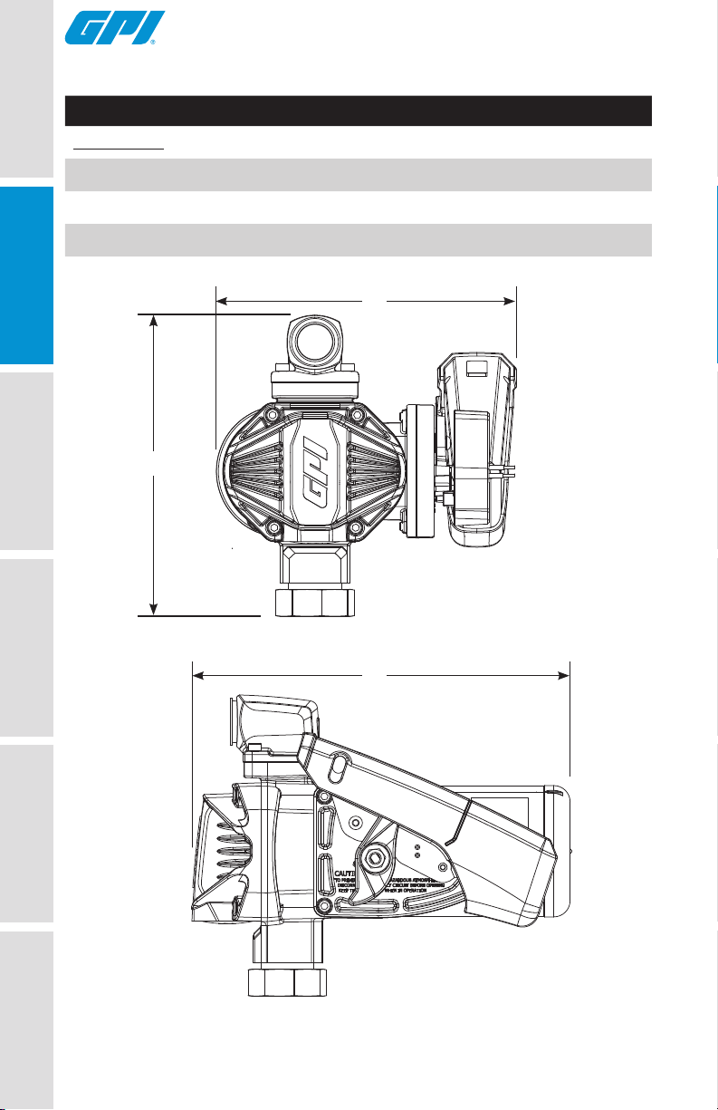
SPECIFICATIONS (CONTINUED)
G20-012PO, G20-012MD, G20-012AD
Dimensions
A. Pump Assy Width 9.20 in. (23.36 cm)
B. Pump Assy Height 9.24 in. (23.46 cm)
C. Pump Assy Depth 11.62 in. (29.51 cm)
SAFETY /
ASSEMBLY /
A
SPECIFICATIONS
B
INSTALLATION
C
TROUBLESHOOTING OPERATION GETTING STARTED
REPAIR
MAINTENANCE /
Figure 1
6
Page 7

INSTALLATION INSTRUCTIONS
Coverplates protect the operator from moving
parts. Never operate the pump without coverplates
in place. Never apply electric power to the pump without coverplates
in place. Always disconnect power before repairing or servicing.
GETTING STARTED OPERATION TROUBLESHOOTING
Mechanical Connections
NOTE: All threaded fuel connections must be sealed with thread tape or a
pipe thread sealing compound approved for use with petroleum fuels and
tightened securely to prevent leakage.
NOTE: This pump must be mounted on a vented tank.
NOTE: This pump is designed to mount directly to a standard 2 in. male
pump tank mount adapter (included).
NOTE: This pump is designed to self-prime with dry gears.
If you require a greater initial prime height, coat the gears with fluid by
removing the outlet fitting on the top of the pump and pour a small quantity
of motor oil into the gear cavity. Replace and try again. A foot valve with
pressure relief may be needed to maintain prime.
Install Tank Adapter and Suction Pipe
1. Wrap lower threaded end of the tank adapter with three or four turns of
thread tape (see Figure 2). Using a wrench, tighten the adapter snugly into
the fuel tank.
NOTE: For Aluminum Tank Installation - To prevent thread galling of
aluminum fittings, always prepare the threads for assembly using an
anti-seize compound such as Loctite® 567™, Hernon® Dripstop® 940 or
equivalent.
2. Using pliers, remove the plastic plug from inlet port on bottom of pump.
Place the spin collar gasket into the inlet fitting on the bottom of the
pump.
3. Wrap the threaded end of suction pipe with three or four turns of thread
tape (see Figure 3). Thread the suction pipe into the inlet port on the
bottom of the pump and hand tighten until snug.
NOTE: If your tank is 15” - 24” deep, do not use the included suction pipe
extension; if your tank is 24” - 40” deep, attach the suction pipe extension
(see Figure 4).
SPECIFICATIONS
SAFETY /
INSTALLATION
ASSEMBLY /
MAINTENANCE /
REPAIR
7
Page 8

INSTALLATION INSTRUCTIONS (CONTINUED)
GETTING STARTED
Figure 3Figure 2
SAFETY /
ASSEMBLY /
OPERATION
SPECIFICATIONS
INSTALLATION
24” - 40” Extension Pipe
Figure 4
Install Pump on Tank
1. Clean the tank interior of all dirt and foreign material.
2. Place the pump with suction pipe installed on the tank fitting and tighten
securely. Make sure the pump’s spin collar is not cross-threaded.
Install Nozzle Cover
1. Using a 4mm Hex wrench, install nozzle cover using (1) M6-1.0 x
14mm BHCS in lower hole (see Figure 5).
NOTE: For model G20-012PO only, DO NOT install nozzle cover until after
power cord has been installed. See Install Power Cord (G20-012PO model)
section.
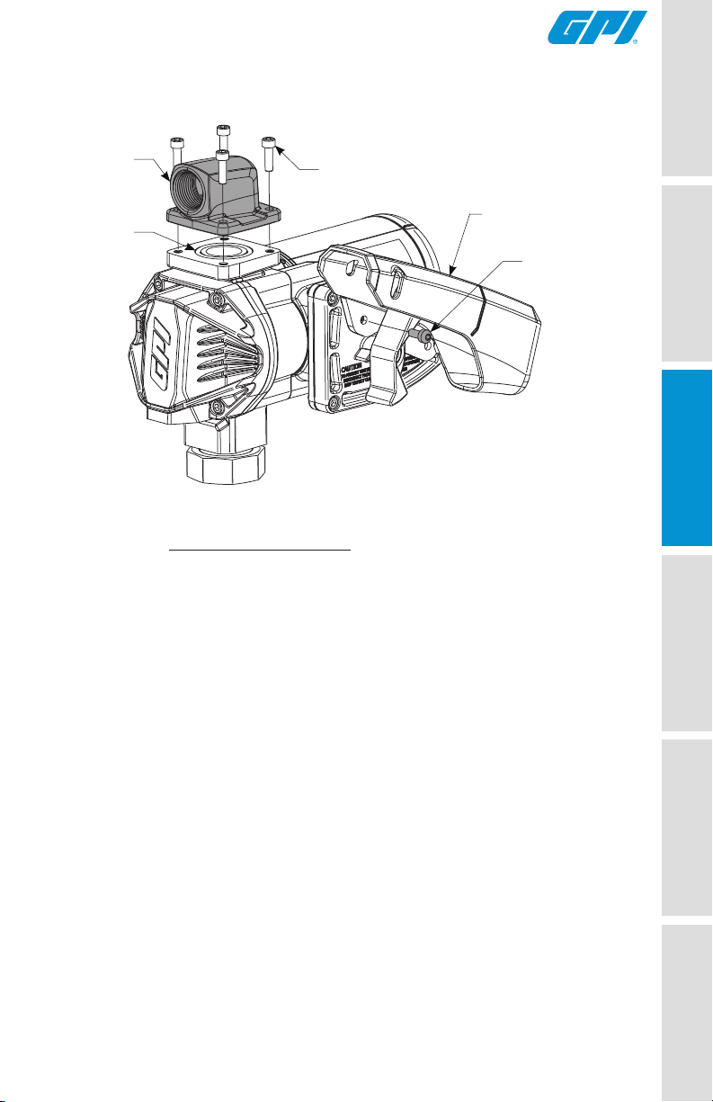
Install 1 in. NPT Outlet Adapter
1. Remove plastic plug from outlet port of pump.
2. Install #222 O-ring into outlet port. Make sure O-ring is seated properly.
3. Using a 5mm Hex wrench, install the (4) M6-1.0 x 20mm SHCS
into the 1 in. NPT outlet adapter in desired direction on outlet port
(see Figure 5).
15” - 24” Telescoping Suction Pipe
TROUBLESHOOTING
REPAIR
8
MAINTENANCE /
Page 9
INSTALLATION INSTRUCTIONS (CONTINUED)
GETTING STARTED
Outlet
Adapter
#222
O-ring
M6-1.0 x 20mm
SHCS
Nozzle Cover
M6-1.0 x 14mm
BHCS
Figure 5
Install Hose and Nozzle
1. Wrap one end of the dispensing hose with three to four turns of thread
tape and thread into outlet port. Tighten securely using an adjustable
wrench.
2. Wrap opposite end of hose with three or four turns of thread tape
and thread into nozzle. Tighten securely using an adjustable wrench.
3. Place the nozzle into the nozzle holder on the end of the pump motor
housing. Note that the nozzle cannot be placed in the holder unless
the pump switch is OFF (see Figure 9).
SPECIFICATIONS
SAFETY /
INSTALLATION
ASSEMBLY /
OPERATION
TROUBLESHOOTING
MAINTENANCE /
REPAIR
9
Page 10

INSTALLATION INSTRUCTIONS (CONTINUED)
Install Power Cord (G20-012AD & G20-012MD models)
GETTING STARTEDOPERATION
SAFETY /
SPECIFICATIONS
ASSEMBLY /
INSTALLATION
TROUBLESHOOTING
NOTE: This pump is pre-wired for installation in CLASS I, DIVISION 2
locations such as portable fuel tanks, trailers, etc. Connection method to a
battery will depend upon the application.
If pump is to be installed in a CLASS I, DIVISION I
location please contact GPI for the
appropriate product.
Install Power Cord (G20-012PO model)
For installation in unclassified areas, the supplied power cord, fuse and
strain relief grip may be used.
NOTE: These components have not been evaluated as part of the UL
Listed Equipment and are not intended for use in a Hazardous (Classified)
Location.
To install the power cord, remove the (4) M6-1.0 x 20mm SHCS and
electrical coverplate (see Figure 7).
If necessary, trim the power cord to the desired length. Strip 3 to 4 inches
(7.5 to 10 cm) of outer insulation from the power cord end. Then strip 1/2
inch (1.3 cm) of insulation from the power cord wires.
Slide the strain relief grip onto the power cord so that the threaded end of
the strain relief grip faces the stripped power wires (see Figure 6).
Insert the power cord through the 1/2 inch NPT connection on the back
of the pump (see Figure 7). Using wire nuts, connect the black wire to
the black wire and the red wire to the red in the pump’s electrical cavity.
Position the wires inside the electrical cavity and tighten the strain relief grip
securely. Make sure surfaces are clean. Reinstall the electrical coverplate
and switch lever, and tighten securely.
If the pump is to be installed in a Hazardous
(Classified) location, it must be installed by a
licensed electrician and conform to National Fire Protection
Association (NFPA) codes 30 and 70. You as the owner, are
responsible for seeing that the installation and operation of your
pump complies with NFPA codes as well as any applicable state and
local codes. Rigid conduit must be used to install wiring. Note that
the lead wires are factory-sealed isolating the motor from the
junction box.
Failure to follow these wiring instructions may result in death or
serious injury from shock, fire or explosion.
REPAIR
10
MAINTENANCE /
Page 11

INSTALLATION INSTRUCTIONS (CONTINUED)
Figure 6
GETTING STARTED
SPECIFICATIONS
SAFETY /
M6 x 14mm
BHCS
M6 x 20mm
SHCS
Figure 7
Figure 7a
Strain Relief
Green Ground
Screw
Black Wires
Red Wires
External Ground
Screw Location
Power Cord
INSTALLATION
ASSEMBLY /
OPERATION
TROUBLESHOOTING
Install Ground Wire
A grounding connection is provided. It is identified as a green colored
binding head screw in the electrical cavity (see Figure 7). An external
ground can be used instead. To use external ground, remove green ground
screw from electrical cavity and install in location shown (see Figure 7a).
11
MAINTENANCE /
REPAIR
Page 12

INSTALLATION INSTRUCTIONS (CONTINUED)
Connect to a Power Source
GETTING STARTED
SAFETY /
SPECIFICATIONS
ASSEMBLY /
INSTALLATION
OPERATION
TROUBLESHOOTING
Red
Wire
NOTE: Please consult the Owner’s Manual for your vehicle before
proceeding.
IMPORTANT: The pump is designed for use with a 12 V (dc) power
source. Do not attempt connection of any pump to a 24 V (dc), 115 V (ac) or
230 V (ac) power source.
Do not attempt to power the pump from vehicle
wiring smaller than 12 gauge, such as the
cigarette lighter wire, as these thin wires could overheat and
cause a fire.
IMPORTANT: Verify switch is in OFF position (see Figure 9), then route
the electrical wires to the source of the vehicle power system. Be sure to
support the wires as necessary and protect them from sharp edges, heat or
anything that could damage the wires.
1. If the power cord provided is too long, cut to desired length. Using a
utility knife, carefully strip 3 to 4 inches of outer insulation from end of
power cord. DO NOT CUT INSULATION OF INNER WIRES. Next,
using wire strippers, remove 1/4 in. of insulation from the black and red
power cord wires.
2. First disconnect vehicle wiring from the negative ground terminal of
the battery, and then connect as follows: Using wire strippers, carefully
strip 1/4 in. of insulation from both ends of the fuse assembly wire.
3. Insert one end of the fuse assembly wire into a wire connector
(included) and crimp. Insert the red power cord wire into the other
end of the wire connector and crimp. Make sure the fuse assembly is
positioned outside of hazardous areas and as close to the battery as
possible (see Figure 8).
4. Using wire crimpers, attach a terminal post ring (not included) to the
other end of the fuse assembly and a terminal post ring to the end of
the black power cord wire.
5. Connect the red wire/fuse assembly to the positive side of the battery
(see Figure 8).
6. Connect the black power cord wire to the negative side of the battery.
NOTE: Connecting directly to the battery terminal or the end of the battery
cable is recommended.
(+)
Wire Connector
REPAIR
12
MAINTENANCE /
Figure 8
Fuse Assembly
Black Wire
Battery
(-)
Page 13

OPERATION
IMPORTANT: Always follow safety precautions when operating this
equipment. Review the Safety Instructions.
To prevent physical injury or property damage,
observe precautions against fire or explosion
when dispensing fuel. Do not operate the system in the presence
of any source of ignition including running or hot engines, lighted
tobacco products, gas or electric heaters, or any type of electronic
device. A spark can ignite fuel vapors.
Before each use, repair leaks around seals or
connections. Make sure hoses are in good
condition and connections are tight.
NOTE: Make sure the work area is dry.
Make sure the pump is properly grounded. Repair
any corroded or damaged wiring before use.
NOTE: Ensure the tank contains enough fuel.
IMPORTANT: Make sure the fuel is not contaminated with debris. Tighten
loose tank lids regularly.
Dispensing Fuel
1. Remove the nozzle from holder and insert into receiving tank. Turn the
pump on by pushing the switch lever up. Squeeze the handle to start
fuel flow. When done, release the nozzle handle, turn the pump off, and
return the nozzle to its holder.
IMPORTANT: This pump is designed to be self-priming. If fuel is not
delivered within 15 to 20 seconds, turn the pump off and refer to priming
information in the Troubleshooting Section.
An automatic bypass valve prevents pressure
build up when the pump is on with the nozzle
closed. To avoid pump damage, do not run the pump more than
10 minutes with the nozzle closed. Leaving the pump on with the
nozzle closed for more than 10 minutes can damage the pump
components and will void the warranty.
Never leave the pump running without fluid.
Dry running can damage the pump components,
and will void the warranty.
IMPORTANT: This is an intermittent duty pump, after running the pump
for a maximum of 30 minutes, allow it to cool for 30 minutes.
GETTING STARTED
SPECIFICATIONS
SAFETY /
INSTALLATION
ASSEMBLY /
OPERATION
TROUBLESHOOTING
13
MAINTENANCE /
REPAIR
Page 14

OPERATION (CONTINUED)
Motor Protector
NOTE: This pump is equipped with a motor protective device that also
GETTING STARTED
SAFETY /
SPECIFICATIONS
ASSEMBLY /
INSTALLATION
serves as the ON/OFF switch. The motor protective device is not intended
to provide branch protection.
1. If motor is overloaded, the protective device trips and opens the circuit.
This feature protects the motor from damage and must be
reset manually.
2. To reset, turn switch lever OFF and then back ON (see Figures 9
and 10).
3. If the protective device trips again quickly, disconnect from power
source before attempting to troubleshoot the problem. Follow the
instructions provided in the Troubleshooting section of this manual.
4. Make sure the switch lever is OFF before restoring power.
5. Turn switch lever ON and restart.
OPERATION
TROUBLESHOOTING
REPAIR
14
MAINTENANCE /
Figure 9
Figure 10
OFF
position
ON position
Page 15

TROUBLESHOOTING
Symptom Possible Cause(s) Corrective Action
Motor does not run 1. Fuse blown 1. Inspect fuse in fuse holder on
2. Switch defective 2. Remove switch coverplate
3. Switch or electrical
connections are faulty
4. Circuit breaker tripped 4. Turn power off at source.
5. Motor damaged 5. Replace pump
power cord. If blown, replace
and inspect switch. Replace,
if necessary
3. Inspect for damaged fuse,
defective wiring or switch or
improper electrical connections.
Replace as needed and
reinstall
Inspect the pump thoroughly;
clean or repair. Reset circuit
breaker by turning the power
switch off then back on
GETTING STARTED
SPECIFICATIONS
SAFETY /
INSTALLATION
ASSEMBLY /
Motor runs but
does not pump
1. Motor running backwards
due to incorrect polarity
2. Poor connections
or low voltage
3. Fuel level low 3. Fill tank
4. Strainer clogged or
defective
5. System air leak 5. Tighten all pump fittings and
6. Suction pipe clogged,
damaged or missing
7. Gear coverplate or O-ring
damaged
8. Bypass poppet
O-ring worn or missing
9. Bypass poppet binding
or damaged
1. Connect red wire to positive
(+) ungrounded side of
battery. Motorshaft should turn
clockwise
2. Make sure electrical
connections are secure. Check
battery voltage
4. Remove pump coverplate.
Remove and clean strainer.
Install again
connections. Inspect suction
pipe for leaks or damage
6. Remove pump from tank.
Inspect suction pipe. Clean
or replace, as necessary
7. Remove and inspect the
coverplate and O-ring.
Replace, as necessary. (see
Maintenance/Repair section)
8. Inspect O-ring (see
Maintenance/Repair section).
Replace, if necessary
9. Remove the bypass poppet,
spring, and O-ring. Clean
cavity. Inspect and replace
components, if needed
OPERATION
TROUBLESHOOTING
MAINTENANCE /
REPAIR
15
Page 16

TROUBLESHOOTING (CONTINUED)
Symptom Possible Cause(s) Corrective Action
Low flow rate 1. Strainer partially clogged 1. Remove the strainer
GETTING STARTED
2. Poor connections
or low voltage
3. Fuel tank empty 3. Fill tank
coverplate. Remove
and clean the strainer.
Install again
2. Make sure electrical
connections are secure.
Also check battery voltage
SAFETY /
SPECIFICATIONS
Motor stalls when
operating in bypass
ASSEMBLY /
INSTALLATION
mode
OPERATION
4. Suction pipe clogged
or damaged
5. System air leak 5. Tighten all pump fittings and
6. Using off-the-shelf
automatic nozzle
1. Motor protector activated 1. Turn off switch. Allow motor
2. Wiring defective 2. Use Wiring instructions in the
3. Bypass poppet binding
or damaged
4. Motor damaged 4. Replace pump
4. Remove pump from tank.
Inspect suction pipe. Clean
or replace, as necessary
connections. Inspect suction
pipe for leaks or damage.
Replace, as necessary
6. Factory-supplied automatic
nozzle is recommended
to cool, then turn on switch
Installation Section to ensure
proper connections
3. Using instructions in the
Repair Section, remove the
bypass poppet, spring and
O-ring. Clean cavity. Inspect
components and replace,
as necessary
TROUBLESHOOTING
REPAIR
16
MAINTENANCE /
Page 17

TROUBLESHOOTING (CONTINUED)
Symptom Possible Cause(s) Corrective Action
Switch fails to operate
motor
1. Switch or electrical
connections faulty
2. Motor protector activated 2. Turn off switch. Allow motor
3. Motor damaged 3. Replace pump
1. Inspect for blown fuse,
defective wiring or switch,
or improper electrical
connections. Refer to Switch
Replacement instructions in
the Repair Section
to cool, then turn on switch
GETTING STARTED
SPECIFICATIONS
SAFETY /
Overheating of motor 1. Duty cycle too long 1. Pump operation should not
2. Running too long in
bypass mode
3. Strainer clogged 3. Remove strainer coverplate.
4. Suction pipe clogged
or damaged
exceed the standard duty
cycle of 30 minutes ON, and
30 minutes OFF. Allow the
pump to cool for 30 minutes
2. Limit bypass operation to
10 minutes
Remove and clean strainer.
Install again
4. Remove pump from tank.
Inspect suction pipe. Clean or
replace, as necessary
INSTALLATION
ASSEMBLY /
OPERATION
TROUBLESHOOTING
17
MAINTENANCE /
REPAIR
Page 18

MAINTENANCE
GETTING STARTED
NOTE: This pump is designed for minimum maintenance. The motor
bearings are self-lubricating. Inspect the pump and components regularly
for fuel leaks and make sure the hose and power cord are in good condition.
Keep the pump exterior clean to help identify leaks.
IMPORTANT: Do not use this pump for water, chemicals or herbicides.
Dispensing any fluid other than those listed in this manual (see BEFORE
YOU BEGIN: Fueling Requirements at front of manual) may damage the
pump. Use of the pump with unauthorized fluids will void the warranty.
SAFETY /
ASSEMBLY /
SPECIFICATIONS
INSTALLATION
Clean or Replace Strainer
1. Turn the pump off and disconnect from power. Using 5mm hex wrench,
remove the coverplate, O-ring, and inlet strainer and inspect for
damage or clogs (see Figure 11). Clean the strainer with a soft-bristled
brush and solvent. If the strainer is very dirty, compressed air may be
used. If damaged, replace the strainer.
2. Clean the coverplate and O-ring. Coat the O-ring lightly with grease.
Reinstall the strainer, O-ring and coverplate. Ensure the O-ring is
properly seated and tighten securely.
Coverplate O-ring
Strainer
Coverplate
TROUBLESHOOTING OPERATION
MAINTENANCE /
Figure 11
REPAIR
18
Page 19

REPAIR
IMPORTANT: Carefully inspect all parts for wear or damage. Replace
components, as necessary. The Illustrated Parts List gives information
on replacement parts and kits. Review the Safety Instructions before
proceeding.
Observe precautions against electrical shock
when servicing the pump. Always disconnect
power before repairing or servicing. Never apply electrical power
to the system when any of the coverplates are removed.
Avoid prolonged skin contact with petroleum
fuels. Use protective goggles, gloves and aprons
in case of splashing or spills. Change saturated clothing and wash
skin promptly with soap and water.
Service O-rings
NOTE: A Wet Seal Kit contains all seals for your pump and should be
on hand when performing repairs. Old seals may then be replaced with
new seals.
1. In general, when inspecting O-rings, look for breaks, wear, and signs
of deterioration, such as swelling.
2. Replace, as necessary.
3. Before seating, coat O-rings with light grease.
GETTING STARTED
SPECIFICATIONS
SAFETY /
INSTALLATION
ASSEMBLY /
19
OPERATION TROUBLESHOOTING
MAINTENANCE /
REPAIR
Page 20

REPAIR (CONTINUED)
Replace Gears
GETTING STARTED
SAFETY /
SPECIFICATIONS
ASSEMBLY /
INSTALLATION
1. Turn the pump OFF and disconnect from power.
2. Using 5mm hex wrench, remove the gear coverplate and O-ring (see
4. Remove the gears.
5. Inspect gears for wear and damage. Replace,
6. Wipe the gear cavity with a clean cloth.
8. Replace the gears.
9. Make sure the gear coverplate O-ring is securely in place.
10. Clean Bypass poppet (see Figure 13).
Figure 12).
as necessary.
Tighten the coverplate to the housing.
Gears
Coverplate Seal O-ring
Coverplate
TROUBLESHOOTING OPERATION
MAINTENANCE /
Figure 12
REPAIR
20
Page 21

REPAIR (CONTINUED)
Clean and Replace Bypass Poppet
1. Turn the pump OFF and disconnect from power.
2. Using a 5mm Hex wrench, remove the coverplate from the pump.
3. With a 10mm Hex wrench remove the pipe plug from the coverplate,
and remove the bypass poppet spring, O-ring, bypass poppet and
orifice seal (see Figure 13).
4. Inspect the O-ring and replace as necessary
NOTE: Replace O-ring if damaged, swollen or loose-fitting
(see Wet Seal Kit).
5. With a clean cloth, wipe the poppet components and replace.
6. Before seating, coat O-ring with light grease.
7. Install coverplate.
GETTING STARTED
SPECIFICATIONS
SAFETY /
INSTALLATION
ASSEMBLY /
Coverplate
Orifice Seal
Bypass Poppet
Figure 13
OPERATION TROUBLESHOOTING
Spring
O-ring
Pipe Plug
MAINTENANCE /
REPAIR
21
Page 22

REPAIR (CONTINUED)
Replace Motor Shaft Seal
GETTING STARTED
SAFETY /
SPECIFICATIONS
1. Turn the pump OFF and disconnect from power.
2. Using a 5mm Hex wrench, remove the (4) M6 x 80mm SHCS on
3. Remove motor shaft seal from pump housing (see Figure 14).
4. Press a new motor shaft seal evenly in the pump housing until seated.
5 Reinstall pump housing with gear coverplate, gears and fittings.
gear coverplate and (1) M6 x 35mm SHCS located on back of pump
housing. Separate pump housing and fittings from drive shaft (see
Figure 14).
Lubricate the seal with a lightweight motor oil.
ASSEMBLY /
TROUBLESHOOTING OPERATION
INSTALLATION
M6 X 35mm
SHCS
M6 X 80mm
SHCS
Motor shaft
seal
Figure 14
REPAIR
22
MAINTENANCE /
Page 23

REPAIR (CONTINUED)
Replace Power Switch
1. Turn the pump OFF and disconnect from power.
2 Using a 4mm Hex wrench remove the M6 BHCS and nozzle cover.
4. Remove the (4) M6 SHCS and electrical coverplate from the motor
housing.
5. Remove the (1) #10 truss head screw and switch bracket with switch
assembly (see Figure 15).
6. Unscrew both #6 machine screws and remove the switch assembly
from the switch bracket.
7. Unscrew both blade terminals and remove red pump wires from the
back of the switch (see Figures 15 and 16). Take note of which wire
is attached to each blade terminal for reinstallation.
8. Install a new switch by reversing the above procedure. Insert the switch
assembly into the pump cavity. Reinstall all components.
Switch Assembly
Switch Bracket
Electrical Coverplate
Nozzle
Cover
GETTING STARTED
SPECIFICATIONS
SAFETY /
INSTALLATION
ASSEMBLY /
#6 Screw
#10 Screw
Figure 15
Blade Terminals
To Motor
From Battery
Figure 16
M6 BHCS
M6 SHCS
OFF
ON
Remove Pump From Tank
1. Turn the pump OFF and disconnect from power.
2. Unthread and lift the pump and suction pipe straight up from the tank
adapter.
3. Elevate the nozzle and hose to allow excess fuel to drain into the tank.
4. Wipe the entire system with a clean cloth.
OPERATION TROUBLESHOOTING
MAINTENANCE /
REPAIR
23
Page 24

REPAIR PARTS ILLUSTRATION FOR G20-012PO, G20-012MD
AND G20-012AD
Do not return the pump or parts without prior
GETTING STARTED
Department. Due to strict government regulations, GPI cannot accept
parts unless they have been drained and cleaned.
approval from the GPI Customer Service
2
SAFETY /
4
SPECIFICATIONS
ASSEMBLY /
INSTALLATION
PARTS & SERVICE
TROUBLESHOOTING OPERATION
REPAIR
24
MAINTENANCE /
4
4
1
3
5
4
For warranty consideration, parts, or other service information, please
contact your local distributor. If you need further assistance, contact the GPI
Customer Service Department in Wichita, Kansas, during normal business
hours.
A toll free number is provided for your convenience.
1-800-835-0113
To obtain prompt, efficient service, always be prepared with the following
information:
• The model number of your pump.
• The serial number or manufacturing date code of your pump.
• Part descriptions and numbers.
For warranty work, always be prepared with your original sales slip or other
evidence of purchase date.
Page 25

REPAIR PARTS LIST FOR G20-012PO, G20-012MD AND
G20-012AD
Ref.
No.
1
2
3
4
5
(▲) Available as part of kit only.
Description
Gear Kit 162501-01
Gear Coverplate O-ring #226 ▲ 1
Gears ▲ 2
Outlet Hardware Kit 162516-503
5mm Hex Key (not shown)
M6-1.0 x 20mm SHCS
Outlet Port O-ring #222 ▲ 1
Switch Assembly 902006-555
Seal Kit 162502-01
Bypass Valve Orice Seal
Bypass Poppet O-ring #920
Gear Coverplate O-ring #226 ▲ 1
Outlet Port O-ring #222 ▲ 1
Motor Shaft Seal ▲ 1
Electrical Coverplate Seal ▲ 1
Bung Adapter Kit 110909-1
Bung Adapter
Gasket
Part Number Qty.
▲ 1
▲ 4
▲ 1
▲ 1
▲ 1
▲ 1
GETTING STARTED
SPECIFICATIONS
SAFETY /
1
INSTALLATION
ASSEMBLY /
OPERATION TROUBLESHOOTING
IMPORTANT: Please contact GPI before returning any parts. It may be
possible to diagnose the trouble and identify needed parts in a telephone
call. GPI can also inform you of any special requirements you will need to
follow for shipping fuel dispensing equipment.
IMPORTANT: In order to preserve the UL Listing for the motor, do not
attempt to service the motor. For products serviced outside the factory,
the UL nameplate must be defaced to indicate that the equipment may
no longer meet the requirements for UL Listing. This does not apply to
products serviced outside the factory under the UL program for Rebuilt
Motors for Use in Hazardous Locations.
MAINTENANCE /
REPAIR
25
Page 26

GETTING STARTED
SAFETY /
SPECIFICATIONS
ASSEMBLY /
INSTALLATION
NOTES
TROUBLESHOOTING OPERATION
MAINTENANCE /
REPAIR
26
Page 27

NOTES
GETTING STARTED
SPECIFICATIONS
SAFETY /
INSTALLATION
ASSEMBLY /
OPERATION TROUBLESHOOTING
MAINTENANCE /
REPAIR
27
Page 28

GPI® TWO-YEAR LIMITED WARRANTY
Great Plains Industries, Inc. 5252 E. 36th Street North, Wichita, KS USA 67220-3205,
hereby provides a limited warranty against defects in material and workmanship on all
products manufactured by Great Plains Industries, Inc. This product includes a 2 year
warranty from date of purchase as evidenced by the original sales receipt. A 30 month
warranty from product date of manufacture will apply in cases where the original sales
receipt is not available. Reference product labeling for the warranty expiration date based
on 30 months from date of manufacture. Manufacturer’s sole obligation under the foregoing
warranties will be limited to either, at manufacturer’s option, replacing or repairing defective
goods (subject to limitations hereinafter provided) or refunding the purchase price for
such goods theretofore paid by the buyer, and buyer’s exclusive remedy for breach of any
such warranties will be enforcement of such obligations of manufacturer. The warranty
shall extend to the purchaser of this product and to any person to whom such product is
transferred during the warranty period. This warranty shall not apply if:
A. the product has been altered or modified outside the warrantor’s duly appointed
representative;
B. the product has been subjected to neglect, misuse, abuse or damage or has been
installed or operated other than in accordance with the manufacturer’s operating
instructions.
To make a claim against this warranty, contact the GPI Customer Service Department at
316-686-7361 or 800-835-0113.
Or by mail at:
Great Plains Industries, Inc.
5252 E. 36th St. North
Wichita, KS, USA 67220-3205
The company will guide you through a product troubleshooting process to determine
appropriate corrective actions.
GREAT PLAINS INDUSTRIES, INC., EXCLUDES LIABILITY UNDER THIS WARRANTY
FOR DIRECT, INDIRECT, INCIDENTAL AND CONSEQUENTIAL DAMAGES INCURRED
IN THE USE OR LOSS OF USE OF THE PRODUCT WARRANTED HEREUNDER.
The company herewith expressly disclaims any warranty of merchantability or fitness for
any particular purpose other than for which it was designed.
This warranty gives you specific rights and you may also have
other rights which vary from U.S. state to U.S. state.
Note: In compliance with MAGNUSON-MOSS CONSUMER WARRANTY ACT –
Part 702 (governs the resale availability of the warranty terms).
© 2019 Great Plains Industries, Inc., All Rights Reserved.
Great Plains Industries, Inc. / 800-835-0113 / GPI.net
922138-01 Rev- 3/2019
 Loading...