

Page 1

Industrial Grade
5252 East 36th Street North
Wichita, KS USA 67220-3205
TEL: 316-686-7361
FAX: 316-686-6746
1- 888 -99 6-3 837
09 COMPUTER
ELECTRONICS
Owner’s Manual
09/11
Rev. F 920709-05
Page 2
To the owner…
Congratulations on receiving your
GPI Industrial Grade Computer
Electronics. We are pleased to provide you with a product designed
to give you maximum reliability and
efciency.
Our business is the design, manufacture, and marketing of liquid handling, agricultural, and recreational
products. We succeed because we
provide customers with innovative,
reliable, safe, timely, and competitively-priced products. We pride
ourselves in conducting our business
with integrity and professionalism.
We are proud to provide you with a
quality product and the support you
need to obtain years of safe, dependable service.
President
Great Plains Industries, Inc.
TABLE OF CONTENTS
General Information
Installation
Operation
Calibration
.................................... 3
...................................... 4
.................................... 5
User Conguration........................ 6
Maintenance
Troubleshooting
Specications
Parts
........................................... 10
Service........................................ 10
WEEE Directive
...................... 2
................................. 7
............................ 8
............................... 9
.......................... 10
GENERAL INFORMATION
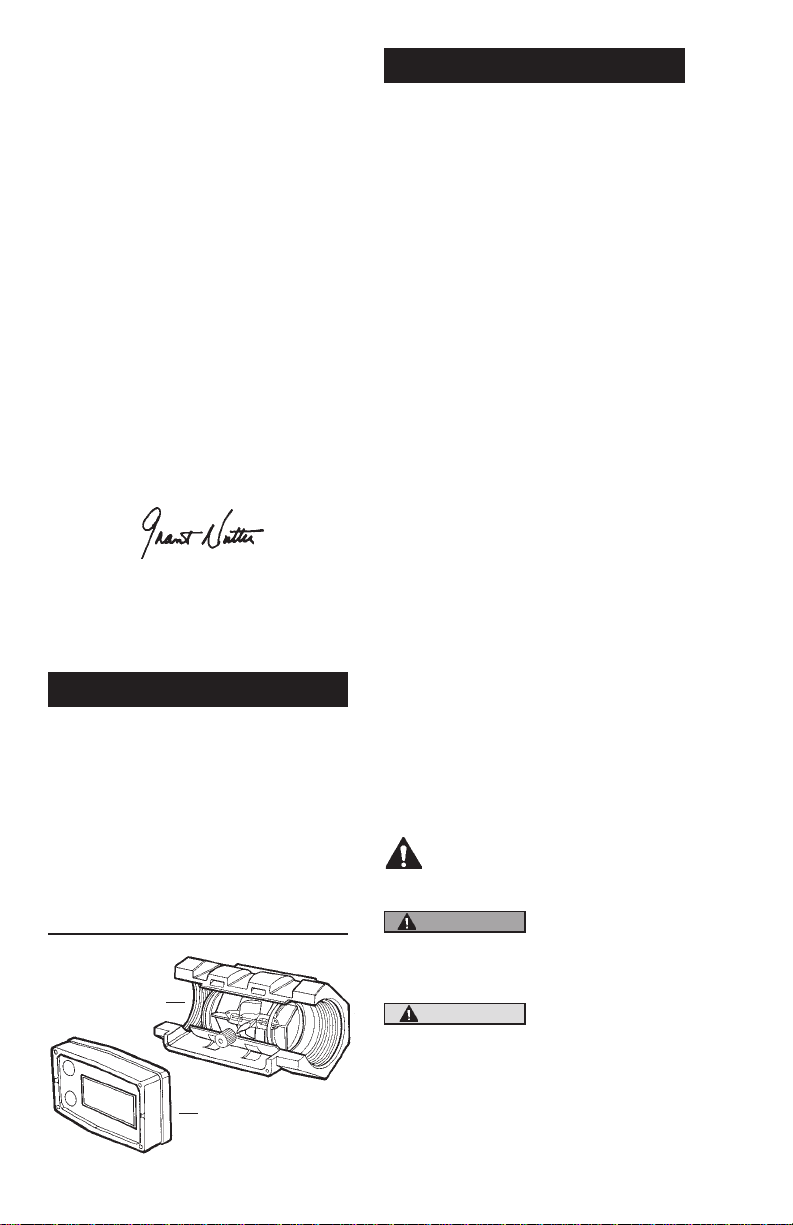
This manual will assist you in operating and maintaining the Computer Electronics of the GPI Industrial Grade Meters. (See Figure 1)
Calibration details are given in this
manual. Information on turbine housings and accessory modules are
contained in other manuals. Please
reference those as necessary.
Figure 1
Turbine Housing
Computer Electronics
(Sold Separately)
2
Before Getting Started
Take the time to fully acquaint yourself with all information about the
components of your GPI Electronic
Digital Meter. If you need assistance,
contact the distributor from whom
you purchased your computer.
This symbol is used throughout the manual to call your
attention to safety messages.
WARNING
CAUTION
Warnings alert
you to the potential for personal
injury.
Caut i o n s call
your attention to
practices or procedure s w h i c h
may damage your
equipment.
Page 3
Notes give information that can
improve efciency of operations.
It is your responsibility to make sure
that all operators have access to adequate instructions about safe operating and maintenance procedures.
Read Me!
For your safety, review the major
warnings and cautions below before
operating your equipment.
WARNING
The apparatus enclosure may
contain aluminum and is considered to constitute a potential risk
of ignition by impact or friction.
Care must be taken into account
during installation and use to
prevent impact or friction.
WARNING
Part of the enclosure is constructed from plastic. To prevent
the risk of electrostatic sparking
the plastic surface should only
be cleaned with a damp cloth.
1. This equipment is approved to
handle only uids that are compatible with all wetted materials.
2. Wh en me asur ing fl amma ble
liquids, observe precautions
against re or explosion.
3. When handling hazardous liquids, always follow the liquid
manufacturer’s safety precautions.
4. Wh en working in haz ardous
environments, always exercise
appropriate safety precautions.
5. For best results, always verify
accuracy before use.
Product Description
These computer electronics are
designed specically for use on GPI
Industrial Grade Turbine Housings.
They are also designed to work with
several accessory output modules.
The CMOS, microprocessor-based
electronics have extremely low power requirements and data retention
capabilities in both RAM and ROM.
Information is clearly displayed on
a large 6-digit LCD readout with
two-point oating decimal for totals
from .01 to 999,999. All operations
are easily accessed with the two
buttons on the front panel.
Liquid flows through the turbine
housing causing an internal rotor to
spin. As the rotor spins, an electrical
signal is generated in the pickup coil.
This pulse data is translated from
the turbine into calibrated ow units
shown on the computer’s readout.
Upon receipt, examine your equipment for visible damage. The compu ter is a prec isio n meas urin g
instrument and should be handled as
such. If any items appear damaged
or missing, contact your distributor.
Make sure your computer model
meets your specic needs. Refer to
the Specications Section to conrm
required features. The model number
of your computer is displayed on the
lower front side of the computer and
also underneath a battery.
INSTALLATION
If you ordered your computer electronics with a turbine housing, it is
installed at the factory.
If you ordered your computer separately from your turbine, simply mount
the computer on the turbine with the
four screws at the corners of the
faceplate. Make sure the seal is fully
seated before tightening the screws.
3
Page 4
If you ordered the computer with
turbine and an accessory module,
please review and thoroughly understand all installation instructions
before proceeding.
All GPI turbines are designed to
measure ow in only one direction.
The direction is indicated by the arrow cast-molded in the turbine outlet.
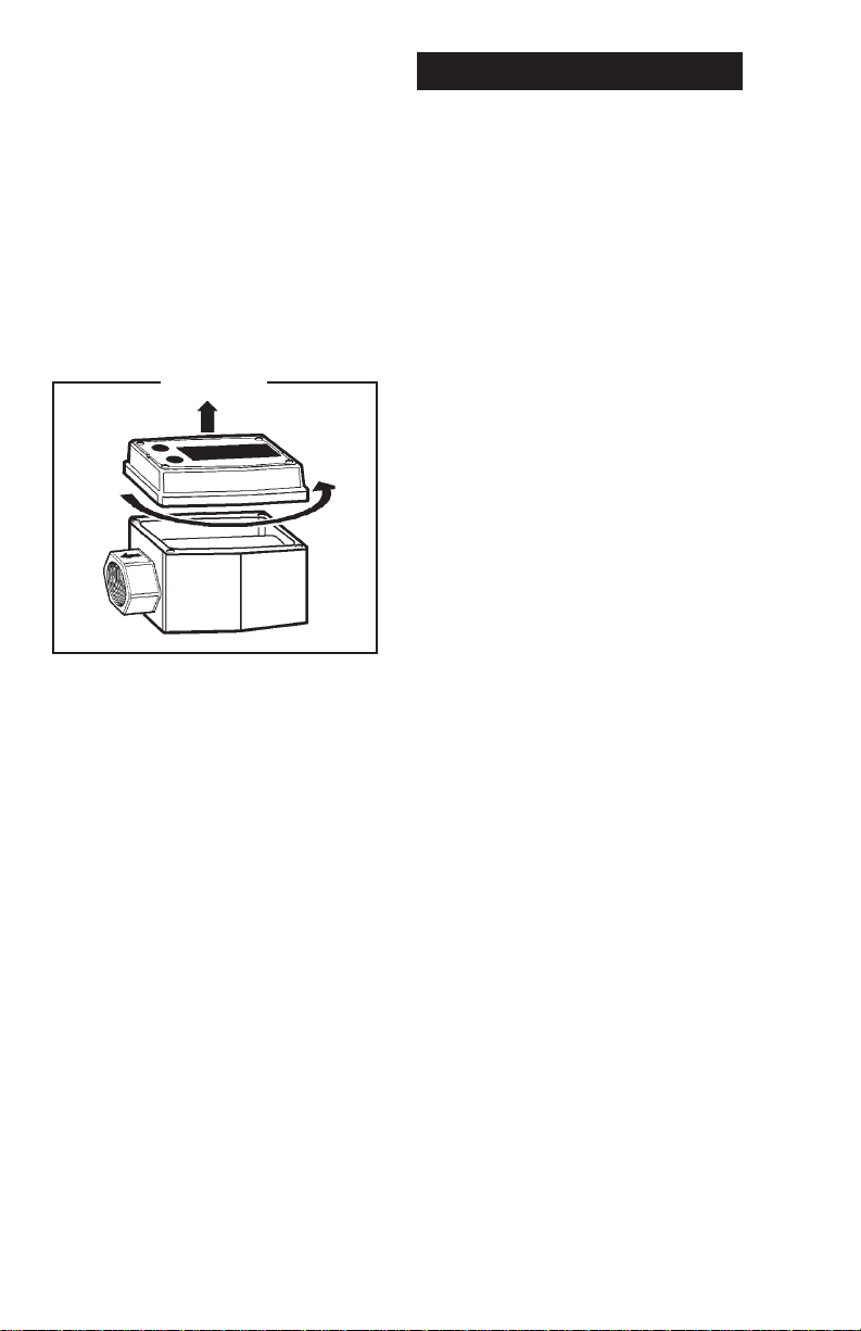
If the computer display is upside
down, remove the four screws, turn
the display 180 degrees and reinstall
the screws. See Diagram 1.
Diagram 1
Avoid electronically “noisy” environments. Install at least 6 inches
(15.2 cm) away from motors, relays,
or transformers.
Our computer electronics are Factory
Mutual Approved, C-UL Classied
and carry a Class 1, Division 1 Approval for hazardous environments.
In addition, GPI meters have NEMA
Type 4 enclosures.
To ensure accurate measurement,
remove all air from the system before use.
It is strongly recommended that accuracy be veried prior to use. To do
this, remove all air from the system,
measure an exact known volume
into an accurate container, and verify
the volume against the readout or
recording equipment. If necessary,
use a correction factor to gure nal
volume. For best results, accuracy
should be veried periodically as part
of a routine maintenance schedule.
4
OPERATION
Computer Display
All operations are reected in the
LCD readout. The large center digits
indicate amounts, where smaller
words or “icons” located above and
below indicate specic information
regarding totals, ow, calibration and
units of measure.
Activate the Meter
Computer is on continuously and always ready to perform. The computer
is powered by eld replaceable batteries. When display becomes dim,
faded or the low battery message
appears (see below), the batteries
need to be replaced. Reference the
Maintenance Section for details.
Batch and Cumulative
Totals
The computer maintains two totals.
The Cumulative Total provides continuous measurement and cannot
be manually reset. The Batch Total
can be reset to measure ow during
a single use. The Cumulative Total is
labeled with TOTAL 1, Batch Total is
labeled TOTAL 2 BATCH.
When the Cumulative Total reaches
a display reading of 999,999 the
computer will highlight an X10 icon.
This indicates to the operator that a
zero must be added to the 6 digits
shown. When the next rollover occurs,
the computer will highlight an X100
icon. This indicates to the operator
that two zeroes must be added to
the 6 digits shown.
Press the DISPLAY button briey to
switch between the TOTAL 1, TOTAL
2 BATCH and FLOWRATE. Press
DISPLAY briey to display the TOTAL
2 BATCH. Hold the DISPLAY button
for 3 seconds to reset the Batch Total
to zero.
Page 5

When uid is owing through the
meter, a small propeller icon is highlighted.
NOTE: Totalization counts total units
without differentiating between
gallons, litres or eld calibrated
units.
Flowrate Feature
(some models)
To use this feature, press and release DISPLAY until FLOWRATE
icon appears. The factory set time
base will be highlighted to the right of
FLOWRATE (M = minutes, H = hours,
D = days). When FLOWRATE is invoked, the display will be indicating
rate of ow.
Switching between different units will
not corrupt the Total’s contents. For
example, in GL mode, the computer
totalizes 10.00 gallons, if the user
switches to LT mode, the display will
read 37.85 litres (the same volume,
different unit).
The “eld” calibration may be set by
the user, and can be changed or modied at any time using the calibration
procedure described in the Calibration Section. Totals or owrate derived
from the eld calibration are invoked
when the FAC icon is no longer visible
on the top line of the display.
CALIBRATION
Factory and Field
Calibration
All calibration information is visible to
the user as icons on the top line of
the display, above the numeric digits.
All units are congured with a “factory” calibration. Both gallons and
litres are available (“GL” or “LT” will
be displayed). While holding the
CALIBRATE button, briey press
DISPLAY to toggle between gallons
and litres. This factory calibration
(indicated with FAC) is permanently
programmed into the computer and
is not user adjustable.
NOTE: Your computer may have oth-
er units of measure programmed
into it. If so, holding the CALIBRATE button and momentarily
pressing the DISPLAY button
will toggle through all factory set
units. Other possible units are:
IGL (imperial gallon), QT (quart),
CF (cubic feet), CM (cubic meter),
BL (42 gal. barrel), CC (cubic
centimeter) or OZ (ounce).
Verify Accuracy Before
Beginning Field Calibration
For the most accurate results,
dispense at a owrate which best
simulates your actual operating conditions. Avoid “dribbling” more uid or
repeatedly starting and stopping the
ow. This can result in less accurate
calibrations.
Make sure you meet the meter’s
minimum owrate requirements:
1/2 in. meter 1 GPM (3.8 LPM)
3/4 in. meter 2 GPM (7.6 LPM)
1 in. meter 5 GPM (18.9 LPM)
1-1/2 in. meter 10 GPM (37.9 LPM)
2 in. meter 20 GPM (75.7 LPM)
The use of a uniformly dependable,
accurate calibration container is
recommended for the most accurate
results. For best results, the meter
should be installed and purged of air
before eld calibration.
Due to high owrate on the 2 inch
meter, it is strongly recommended
that Field Calibration be completed
with a combination of volume and
weight determined with ne resolution scales.
5
Page 6

Field Calibration Necessity
Field Calibration and Factory Calibration are dened in the Operation
Section. Factory calibration settings
are programmed into each computer
during manufacturing, using stoddard
test solvent at 70° F (21° C) for low ow
and 1-inch meters and water at 70° F
(21° C) for 2-inch meters. Settings are
correct for light liquids such as water,
gasoline or diesel. Readings using
the Factory Calibration (FAC) may
not be accurate in some situations,
for example, “heavy” liquids such as
motor oil, under extreme temperature
conditions, non-standard plumbing
congurations or with uids other
than mentioned above.
For improved accuracy under such
conditions, the computer allows for
“eld” calibration, that is, user entry
of custom calibration parameters. A
“single point” calibration may yield
acceptable accuracy when used in
a non-standard application.
Field Calibration
Procedures
(Correction Factor Method)
1. To calibrate, press and hold the
CALIBRATE and DISPLAY buttons for about 3 seconds until
you see FLdCAL. Release both
buttons and you will see CF - 00.0.
You are now in the eld calibration
mode and values from -99.9% to
+99.9% can be entered.
+
2. The
3. The DISPLAY button can then
/– position appears either
as an “underscore” character for
plus, or as a “hyphen” character
for minus. The DISPLAY button selects the position and the
CALIBRATE button toggles this
character.
be pushed to select the numeric
positions. Press the CALIBRATE
button to scroll from 0 to 9. Enter
the percentage of change you
want the display to correct. When
satised with the value, press
both CALIBRATE and DISPLAY
buttons simultaneously. CALEnd
will be displayed and unit will go
back to normal operation, less the
FAC (factory calibration) icon.
4. All enabled units-of-measure remain visible and selectable – the
entered correction will be applied
to all enabled units.
5. To return to factory calibration
(FAC), press and hold both CALIBRATE and DISPLAY buttons for
about 3 seconds until FAcCAL is
displayed. Then release buttons.
Unit should return to normal operation and FAC icon is visible.
USER CONFIGURATION
The “09” series GPI display has
been programmed with many new
features, most of which can be enabled by the end user by way of a
conguration process. By disabling
“unnecessary” features, day-to-day
owmeter operation can be greatly
simplied, making the unit easier to
use. There are several features that
GPI disables by default when shipping standard meters. (For example,
K-Factor Entry Field Calibration, described below.) For more advanced
users, it may be desirable to enable
ALL possible features. User congurable features include:
• Totalizers/Modes Enabled (Cumu-
lative Total, Batch 2 Total, Flowrate
Mode)
• Flowrate Timebase (Units per
Minutes, Hours and Days)
• Factory Calibration Curve Units
Enabled (Gallons, Imperial Gallons, Litres, Quarts, Ounces, Cubic
Feet, Cubic Centimeters, Cubic
Meters or Barrels (42 gal.)
• Dispense/Display or K-Factor En-
try Calibration
6
Page 7

Changing Conguration
Settings
Access to the configuration process is restricted for security until a
“password” is entered. Contact your
distributor or GPI to get the password
and instructions to unlock and reset
conguration settings. This information is also available on the GPI Web
site. Congurations are entered and
stored as six-digit “codes” where
each digit represents a setting for
one of the conguration options. New
conguration settings are stored in
the computer’s long-term memory
and will not be lost either in OFF
mode or during battery change.
K-Factor Entry Field
Calibration
Presently all GPI computers are
programmed with three different
eld calibration methods, only one
of which is active, the “correction/
factor” calibration procedure described above. It is possible to activate “K-Factor entry” or “dispense/
display” eld calibration by changing
conguration settings. Contact your
distributor or GPI to get the correct
password, conguration code, and
instructions for this calibration method. This information is also available
on the GPI Web site.
MAINTENANCE
When batteries are disconnected or
fail, the Batch and Cumulative Totals
will maintain the value they had.
Factory and Field Calibration Curves
are retained in the meter’s computer
when power is lost.
It is strongly recommended that
battery check and terminal cleaning
be a part of a routine maintenance
schedule. Battery terminals should
be cleaned annually. Batteries can be
replaced without removing the meter
from the piping system.
Replace Batteries
1. Remove the corner screws from
the meter face and lift the computer electronics from the turbine.
2. Remove the batteries.
3. Check the battery terminals and
remove any corrosion.
4. Install the new batteries and
make sure the positive posts
are positioned correctly. When
the batteries are installed correctly, the computer powers on
automatically and the readout
displays information.
5. Make sure the seal is fully seated
before placing the computer electronics on the turbine. Tighten the
four screws.
6. Do not clean exterior of computer
assembly with Isopropyl Alcohol.
The computer electronics is powered
by lithium batteries. Removing the
batteries before storing the meter
will extend battery life. If the meter’s
readout should become dim, blank
or the low battery message appears
(see below), the batteries should be
replaced. Replacement batteries can
be ordered from your distributor or
the factory. See details in the Parts
Section.
7
Page 8

TROUBLESHOOTING
Symptom Probable Cause Corrective Action
A. METER IS 1. Field Calibration not per- Field calibrate again or select Factory
NOT
formed properly Calibration.
ACCURATE
2. Factory Calibration not Perform a Field Calibration according
suitable for liquid being to Calibration Section.
measured
3. Meter operated below Increase owrate.
minimum owrate
4. Meter partially clogged Remove meter. Clean carefully. Make
with dried liquid sure rotor spins freely.
5. Turbine bearings partially Remove meter. Clean carefully. Make
clogged with dried liquid sure rotor spins freely.
6. Sealant material Remove meter. Make sure rotor spins
wrapped around rotor freely.
7. Installed too close to Install correctly.
ttings
8. Installed too close to Install correctly.
motors or electrically
“noisy” environment
B. READOUT 1. Batteries weak, dead, or Remove computer, check and replace
FADED OR
not connected batteries if necessary.
BLANK
2. Computer defective Contact the factory.
C. NORMAL 1. Field Calibration not Field Calibrate again or select Factory
FLOWRATE
performed correctly Calibration.
BUT METER
DOES NOT
freely.
COUNT
3. Sealant material Remove meter. Make sure rotor spins
wrapped around rotor freely.
4. Computer defective Contact the factory.
D. REDUCED 1. Meter clogged with dried Remove meter. Clean carefully. Make
FLOWRATE
liquids sure rotor spins freely.
AND METER
2. Below minimum owrate Increase ow.
DOES NOT
COUNT
E. CANNOT GET 1. Wrong button sequence Proceed with calibration according to
METER INTO
the Calibration Section.
FIELD CALI-
2. Computer circuit board Replace computer. Contact the factory.
BRATION
defective
3. Button defective Replace computer. Contact the factory.
2. Rotor stuck or damaged Remove meter. Make sure rotor spins
8
Page 9
SPECIFICATIONS
Standard Features Include:
• 2 Totalizing Registers
• 1 Factory Calibration Curve
• 1 Field Calibration Curve
• Rate of Flow Feature
• Flowrate Time Base in Minutes
Input Pulse Rate:
Minimum Pulse In: DC
Minimum Coil Input: 10 Hz
Maximum Raw: 1,000 Hz
K-Factor:
Minimum: .01 pulses/unit
Maximum: > 999,999 pulses/
unit
Field Calibration Correction:
Minimum: -99.9%
Maximum: +99.9%
Readout Totals:
Min. Display: 0.01
Max. Display: 999,999 (x100)
Temperatures:
Operational: +0° to +140° F
(-18° to +60° C)
Storage: -40° to +158° F
(-40° to +70° C)
If wider operating temperature
ranges are desired, reference
information on GPI Remote Kits.
Power:
Internal Power
Supply: 2 Lithium
Batteries at
3 volts each
Battery Life: 5 years
Optional
External Power
Module: 7-30-volts DC
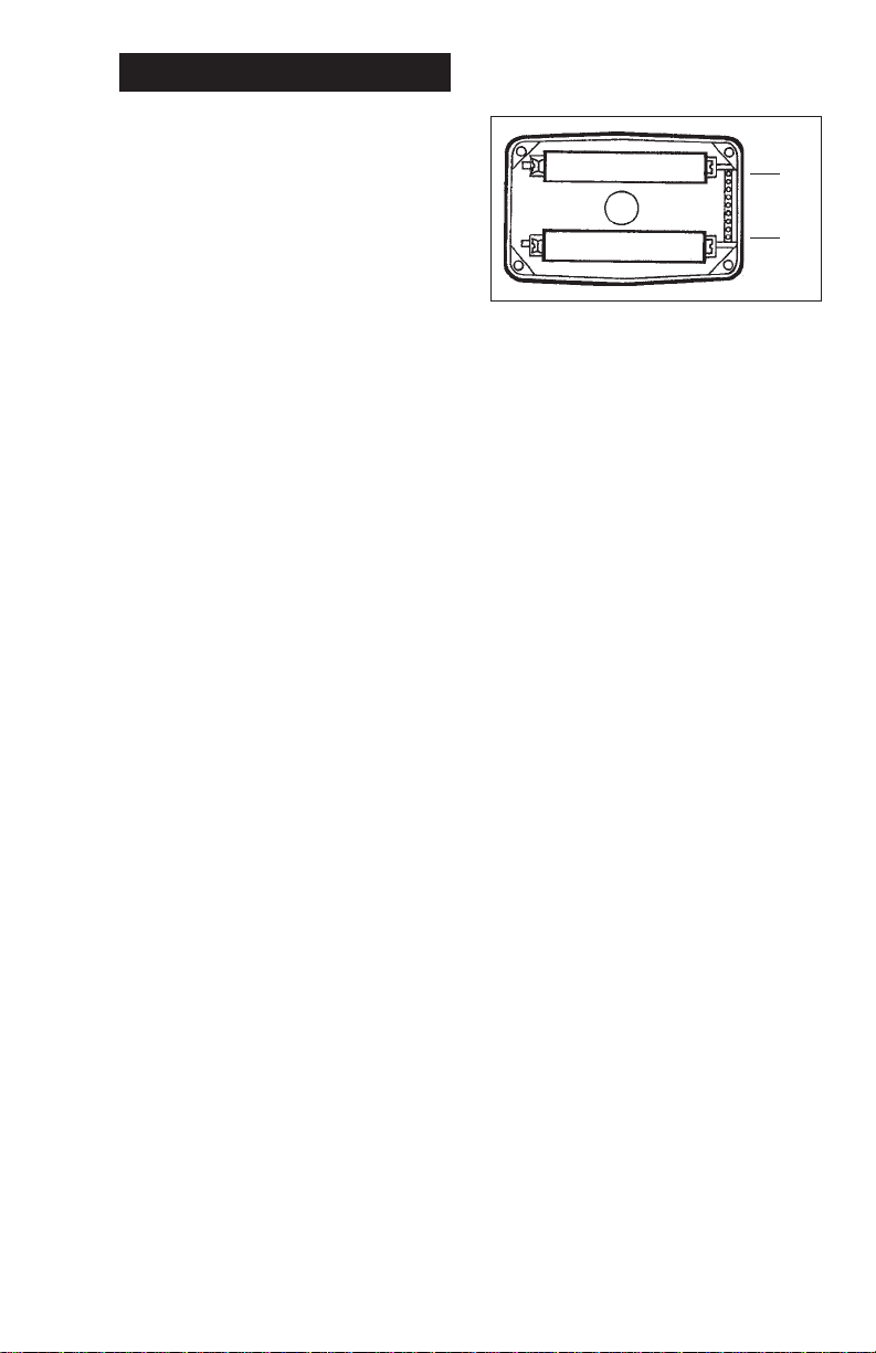
Computer Electronics
Terminal Connections
J 1
J 10
J-1 Reset
Programming interfaces. Not
accessible to user.
J-2 Pulse Signal Output
This supplies a high-level am-
plied open collector signal.
Output will withstand a maximum open-circuit voltage of
60-volts DC and a maximum
closed-circuit of 100 mA.
J-4 Pulse Signal Input
Requires a sine or square
wave with open-circuit voltage of 3-30 volts P-P, a maximum rise/fall rate of 0.01 V/µ
second and a maximum frequency of 750 Hz.
J-5 Power Input
Whe n us ed with Gro u nd
(J1-6), this has reverse polarity protection, but no on-board
voltage regulation. Supplied
voltage may be 5-volts to
10-volts DC.
J-6 Ground
J-7, 8, Programming interfaces. Not
accessible to user.
9, 10
NOTE: Safety approvals are void
if any external connections
are made to computer electronics.
9
Page 10

PARTS
The factory, when provided with
model number and serial number,
can replace your entire Computer
Electronics Assembly.
Order replacement kits, parts, and
accessories with the part numbers
given here.
Part No. Description
113520-1 Battery Replacement Kit
901002-52 Seal
116000-1 Large (5 gal.) Calibration
Container
SERVICE
For warranty consideration, parts,
or other service information, please
contact your local distributor. If you
need further assistance, call the
GPI Customer Service Department
in Wichita, Kansas, during normal
business hours.
1-888-996-3837
To obtain prompt, efcient service,
always be prepared with the following information:
1. The model number of your com-
puter electronics.
2. The serial number or manufactur-
ing date code of your computer
electronics.
3. Specic information about part
numbers and descriptions.
For warranty work always be prepared with your original sales slip
or other evidence of purchase date.
Returning Parts
Please contact the factory before returning any parts. It may be possible
to diagnose the trouble and identify
needed parts in a telephone call. GPI
can also inform you of any special
handling requirements you will need
to follow covering the transportation
and handling of equipment which has
been used to transfer hazardous or
ammable liquids.
CAUTION
Do not return computer electronics or meters without specic
authority from the GPI Customer
Service Department. Due to strict
regulations governing transportation, handling, and disposal of
hazardous or ammable liquids,
GPI will not accept computer
electronics or meters for rework
unless they are completely free
of liquid residue.
CAUTION
Meters not ushed before shipment can be refused and returned to the sender.
WEEE DIRECTIVE
The Waste Electrical and
Electronic Equipment (WEEE)
directive (2002/96/EC) was
approved by the European
Parliament and the Council of
the European Union in 2003.
This symbol indicates that this
product contains electrical and
electronic equipment that may
include batteries, printed circuit boards, liquid crystal
displays or other components that may be subject
to local disposal regulations at your location. Please
understand those regulations and dispose of this
product in a responsible manner.
10
Page 11

Declaration of Conformity
Manufacturer’s Name: Great Plains Industries, Inc.
Manufacturer’s Address: 5252 East 36th Street North
Wichita, KS USA 67220-3205
Declares, that the product:
Product Name: Electronic Digital Meter
Model Numbers: 03*****
A1***********
A2***********
G2*********
Model numbers include all combinations
of an alpha-numeric series as illustrated above.
Conform to the following Standards:
EMC: EN 50081-1 (Reference EN 55022)
EN 50082-1
Energy - Limited Apparatus: EN 50021
I.P. Code: BS EN 60529
Supplementary Information:
“The products comply with the requirements of the EMC
Directive 89/336/EEC and the ATEX Directive 94/9/EC
(ANNEX VIII).”
I, the undersigned, hereby declare that the equipment specied above
conforms to the above Directive(s) and Standard(s).
Signature:
Full Name: Mr. Grant Nutter
Position: President
Great Plains Industries, Inc.
Place: Wichita, KS USA
May 2003
11
Page 12

5252 East 36th Street North
Wichita, KS USA 67220-3205
TEL: 316-686-7361
FAX: 316-686-6746
1- 888 -99 6-3 837
Limited Warranty Policy
Great Plains Industries, Inc. 5252 E. 36th Street North, Wichita, KS USA 67220-3205,
hereby provides a limited warranty against defects in material and workmanship on all
products manufactured by Great Plains Industries, Inc. This product includes a 1 year
warranty. Manufacturer’s sole obligation under the foregoing warranties will be limited
to either, at Manufacturer ’s option, replacing or repairing defective Goods (subject
to limitations hereinafter provided) or refunding the purchase price for such Goods
theretofore paid by the Buyer, and Buyer’s exclusive remedy for breach of any such
warranties will be enforcement of such obligations of Manufacturer. The warranty shall
extend to the purchaser of this product and to any person to whom such product is
transferred during the warranty period.
The warranty period shall begin on the date of manufacture or on the date of purchase
with an original sales receipt. This warranty shall not apply if:
A. the product has been altered or modied outside the warrantor’s duly appointed
representative;
B. the product has been subjected to neglect, misuse, abuse or damage or has
been installed or operated other than in accordance with the manufacturer’s
operating instructions.
To make a claim against this warranty, contact the GPI Customer Service Department
at 316-686-7361 or 888-996-3837. Or by mail at:
The company shall, notify the customer to either send the product, transportation prepaid,
to the company at its ofce in Wichita, Kansas, or to a duly authorized service center.
The company shall perform all obligations imposed on it by the terms of this warranty
within 60 days of receipt of the defective product.
GREAT PLAINS INDUSTRIES, INC., EXCLUDES LIABILITY UNDER THIS WARRANTY FOR DIRECT, INDIRECT, INCIDENTAL AND CONSEQUENTIAL DAMAGES
INCURRED IN THE USE OR LOSS OF USE OF THE PRODUCT WARRANTED
HEREUNDER.
The company herewith expressly disclaims any warranty of merchantability or tness
for any particular purpose other than for which it was designed.
This warranty gives you specic rights and you may also have other rights which vary
from U.S. state to U.S. state.
Note: In compliance with MAGNUSON MOSS CONSUMER WARRANTY ACT – Part
702 (governs the resale availability of the warranty terms).
Great Plains Industries, Inc.
5252 E. 36
th
St. North
Wichita, KS, USA 67220-3205
Factory Mutual Approved
Intrinsically Safe for Class I, II, III, Division 1, All Groups.
GPI is a registered trademark of Great Plains Industries, Inc.
© 2011 by GREAT PLAINS INDUSTRIES, INC., Wichita, KS.
Printed in U.S.A.
09/11
Rev. F 920709-05
 Loading...