

Page 1
FM-530 Series
MECHANICAL
FUEL METER
Owner’s Manual
5252 East 36th Street North
Wichita, KS USA 67220-3205
TEL: 316-686-7361
FAX: 316-686-6746
“A Great Plains Ventures Subsidiary”
12/06 Rev. - 921524-01
www.gpi.net
1-800-835-0113
Page 2

TABLE OF CONTENTS
General Information ............................... 1
Installation .............................................. 1
Operation ................................................ 2
Calibration .............................................. 2
Maintenance ........................................... 3
Troubleshooting ..................................... 4
Specifications ......................................... 4
Illustrated Parts Drawing ....................... 5
Parts and Service .................................... 6
Great Plains Industries, Inc. is a member of the
Petroleum Equipment Institute.
GENERAL INFORMATION
Congratulations on receiving your new
meter. This manual should assist you in
operating and maintaining your mechanical fuel meter. Please take a few moments
to read these instructions before installing
and operating your fuel meter. If you need
assistance, contact the dealer from whom
you purchased your meter. If you need further assistance, please call our Customer
Service Department at 1-800-835-0113.
Safety Instructions
Please read, understand, and follow the
safety instructions given here. It is your responsibility to ensure that all equipment
operators have access to adequate instructions concerning safe operation and maintenance.
1. This meter is designed for use only
with thin viscosity petroleum fuels
such as gasoline (up to 15% alcohol
blends such as E15), diesel fuel (up to
20% biodiesel blends such as B20),
biodiesel (B100) and kerosene.
2. Do not use this equipment for dispensing any fluids other than those for
which it was designed. To do so may
damage the meter and will void the
warranty.
1
3. Observe precautions against fire or
explosion when dispensing fuel. Do
not operate the meter in the presence
of any source of ignition including running or hot engines, lighted cigarettes,
or gas or electric heaters.
4. Any components such as hose, nozzle,
or pump added to your meter must be
statically grounded and approved for
use with petroleum fuels.
5. Avoid prolonged skin contact with
petroleum fuels. Use protective goggles,
gloves, and aprons in case of accidental splashing or spillage. Change
saturated clothing and wash skin contact
areas promptly with soap and water.
The FM-530 Series of Mechanical Fuel
Meters are designed for the field measurement of thin viscosity petroleum fuels
only and are intended for use with pump
systems in the 5 to 30 GPM or 19 to 114
LPM flow range (not intended for gravity flow systems). Using mechanical
gears, these meters translate flow data from
a nutating disc into calibrated units which
are indicated on the face of the meter. This
meter is factory calibrated for diesel fuel.
Field calibration feature is available for
other fluids, see Calibration section.
INSTALLATION
Before installing your meter, review the
safety instructions given above. Examine
your meter to make sure there are no visible signs of shipment damage. Plan your
meter installation by reviewing the following procedures. Your system must be
mounted on a vented tank. If the tank is
unvented, your local dealer or distributor can
supply a pressure cap.
Prior to installation, determine the fitting
angle desired and whether horizontal or
vertical orientation is required.
Rotate Fittings
To rotate inlet and/or outlet fittings, remove
the two nuts and bolts which secure each
fitting. Rotate the fitting to the desired orientation. Make sure the O-ring is fully
seated. Tighten the nuts and bolts snugly.
Page 3
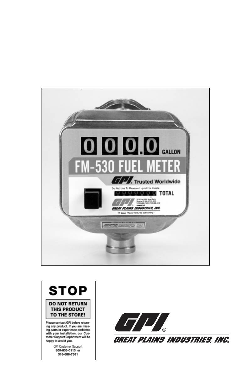
Change Orientation
1. Remove the two Phillips head screws
which secure the cover to the coverplate assembly.
2. Remove the eight pairs of nuts and
bolts which hold the coverplate assembly to the housing. (Figure 1) Note the
position of the reset button.
Figure 1
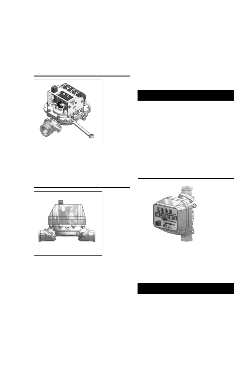
3. Rotate the coverplate assembly and
counter to the desired orientation.
Make sure the flow arrow in the
housing points toward the outlet port.
(Figure 2)
Figure 2
sealant at the inlet fitting in horizontal
orientation.
3. Install the meter on the pump using an
appropriately sized nipple. The meter’s
flow path is marked on the housing
exterior with an arrow pointing toward
the outlet port.
4. Install other system components on the
meter and tighten snugly.
OPERATION
Before use, review the safety instructions
given above. Visually check the meter to
ensure it is securely connected to other system components and there is no leakage.
Promptly wipe spilled fuel from the meter’s
exterior and other system components.
The large meter display represents the
Batch Total for each fuel delivery. Before
dispensing, reset the Batch Total to zero
by pushing the reset button. (Figure 3)
Figure 3
4. Make sure the housing O-ring is fully
seated and firmly tighten the eight nuts
and bolts which secure the coverplate
assembly.
5. Place the reset button in position. Secure
the cover to the coverplate assembly
with the two Phillips head screws.
Meter Installation
1. Remove protective plugs from the
meter inlet and outlet ports.
2. Wrap threaded male connections with
Teflon® tape or use a pipe sealant compound compatible with petroleum
fuels. We recommend Lock-Tite thread
The small display represents the Cumulative Total of all fuel deliveries and cannot
be reset.
CALIBRATION
The meter is accurately calibrated at the
factory for use with diesel fuel. Due to differences in viscosity and flowrates, the
meter may require recalibration to measure
other fuels or to adjust for inaccuracies.
1. Purge air from the meter and fuel system by dispensing fuel into a container
until a full flow occurs. Close the
nozzle.
2
Page 4

2. Reset the meter counter to zero by
pressing the reset button. (Figure 3)
3. Pump into a graduated calibration container to a specified quantity. For the
greatest accuracy, be sure the container
is placed on a level surface and a consistent flow rate is used. When topping
off the calibration container, use a
quick-open and quick-close method
until the mark is reached.
NOTE: Your GPI dealer can supply a cali-
bration container designed for this purpose. (Figure 4)
b. If the meter registered less than the
quantity in the container, turn the
calibration screw clockwise. If the
meter display read more than the
amount in the container, turn the
calibration screw counterclock-
wise.
5. Empty the calibration container and
repeat steps 2 to 4 until the meter registers the quantity in the container.
6. Install the nylon washer and calibration screw cover.
Figure 4
4. Compare the meter display to the quantity in the container. If the display does
not register the quantity on the container, adjust the meter by performing
the following:
a. Gain access to the recessed calibra-
tion screw by turning the calibration screw cover and seal counterclockwise. Remove the cover and
nylon washer. (Figure 5)
Figure 5
MAINTENANCE
The meter’s strainer should be cleaned at
regular intervals, especially when low flow
is detected.
Clean or Replace Strainer
1. Remove the nuts and bolts at the inlet
fitting. Remove the fitting, O-ring, and
strainer.
2. Using a fine brush, clean the strainer.
Replace the strainer as necessary.
3. Wipe clean the inlet, housing, and
O-ring groove. Coat the O-ring with
oil or light grease. Make sure the O-ring
is fully seated. Replace the strainer.
4. Position the inlet fitting in the desired
orientation and tighten the nuts and
bolts until snug.
3
Page 5

TROUBLESHOOTING
Symptom Probable Cause Corrective Action
A. Meter counter does 1. Broken counter assembly. Replace counter.
not operate. (Normal fuel delivery)
B. Meter counter does 1. Clogged strainer in meter. Clean or replace strainer.
not operate. (Little
or no fuel flow)
C. Fuel leakage. 1. Leakage at counter drive shaft. Replace coverplate assembly.
2. Foreign material in counter Remove and clean counter
assembly or nutator assembly. assembly or nutator assembly.
3. Broken nutator disc pin or Install new nutator assembly.
defective nutator assembly.
4. Jammed or broken gear train. Contact GPI Customer Service.
2. Other system components Check all system components
malfunctioning. from tank to nozzle for clogs
and/or malfunctions. Repair as
necessary.
3. Foreign material in nutator Remove and clean nutator
assembly. assembly.
2. Leakage between coverplate and Remove coverplate and inspect
housing. for damaged, missing or
incorrectly seated seal. Replace
as required.
3. Leakage at fittings. Remove fittings and inspect for
4. Leakage at threads. Remove meter and reseal all
damaged, missing or incorrectly
seated seals. Replace as required.
threaded connections with
®
Teflon
tape or pipe thread
sealing compound approved
for use with flammable liquids.
SPECIFICATIONS
Gallon Models Litre Models
Unit of Measure U.S. Gallon Litre
Flow Range 5 to 30 GPM 19 to 114 LPM
Typical Accuracy ± 2% ± 2%
Type Nutating Disc Nutating Disc
Housing Material Aluminum Aluminum
Maximum Working Pressure 50 PSIG 3.4 bar
Inlet/Outlet Fitting Size 3/4", 1" or 1-1/2" 3/4", 1" or 1-1/2"
Threads NPT NPT or BSPP
Maximum Batch Total 999.9 9999
Maximum Cumulative Total 999,999.9 9,999,999
Approximate Ship Weight 6.0 lbs. 2.7 kg
Maximum Dimensions: Width: 8.7 inches 22 cm
Height: 5.9 inches 15 cm
Depth: 5.7 inches 14.5 cm
Note: Accuracy is factory calibrated using diesel fuel. Field Calibration is available on all models.
4
Page 6

ILLUSTRATED PARTS DRAWING
5
Page 7

ILLUSTRATED PARTS LIST
Item No.
No. Part No. Description Req’d.
1 126514-05 Counter Assembly, Gallons ............................................... 1
126514-06 Counter Assembly, Litres .................................................. 1
2 126514-07 Coverplate Assembly, Gallons .......................................... 1
126514-08 Coverplate Assembly, Litres ............................................. 1
3 126010-1 Housing .............................................................................. 1
4 126013-11 Top Cover........................................................................... 1
5 12620239 Decal (Gallon) ................................................................... 1
12620240 Decal (Litre)....................................................................... 1
items not shown:
111014-3 Calibration Screw .............................................................. 1
111026-1 Seal, Calibration Screw ..................................................... 1
111039-2 Cover, Calibration Screw .................................................. 1
904006-16 Washer, Calibration Screw Cover ..................................... 1
Kits and Accessories
126514-03 Gear Assembly Kit, Gallons
A
126514-04 Gear Assembly Kit, Litres
126503-1 Nutator Assembly Kit
B
126509-1 Seal Kit (Housing O-Ring, Fitting O-Rings)
C
126512-1 Hardware Kit (Fitting O-Rings, Strainer, Screws, Nuts)
D
126501-1 Fitting Kit for 3/4-inch NPT (2 Fittings, 2 Fitting O-Rings)
E
126501-2 Fitting Kit for 3/4-inch BSPP (2 Fittings, 2 Fitting O-Rings)
126501-3 Fitting Kit for 1-inch NPT (2 Fittings, 2 Fitting O-Rings)
126501-4 Fitting Kit for 1-inch BSPP (2 Fittings, 2 Fitting O-Rings)
126501-5 Fitting Kit for 1-1/2-inch NPT (2 Fittings, 2 Fitting O-Rings)
126501-6 Fitting Kit for 1-1/2-inch BSPP (2 Fittings, 2 Fitting O-Rings)
PARTS AND SERVICE
For warranty consideration, parts, or other
service information, contact your local distributor. If you need further assistance,
please contact GPI Customer Service Department in Wichita, Kansas during normal business hours at 1-800-835-0113.
To obtain prompt, efficient service, always
be prepared with 1.) the model number of
your meter, 2.) the manufacturing date located on the back of the meter, and 3.) specific information, as necessary, obtained
from the Illustrated Parts List. For warranty
work always be prepared with proof of purchase date.
Please contact GPI before returning any
parts. It may be possible to diagnose the
trouble and identify needed parts without
returning parts. GPI can also inform you
of any special handling requirements you
will need to follow covering the transportation and handling of fuel transfer equipment. Before packing for shipment, make
sure the meter is thoroughly drained and
free of fuel and vapors.
CAUTION! Do not return meters or parts
without specific authority from the GPI
Customer Service Department. Due to
strict regulations governing shipment
of flammable liquids, meters may be
refused and returned to the sender if
sent without authorization.
6
Page 8

Limited Warranty Policy
Great Plains Industries, Inc. 5252 E. 36th Street North, Wichita, KS USA 67220-3205, hereby provides a
limited warranty against defects in material and workmanship on all products manufactured by Great Plains
Industries, Inc. This product includes a 2 year warranty. Manufacturer’s sole obligation under the foregoing
warranties will be limited to either, at Manufacturer’s option, replacing or repairing defective Goods (subject
to limitations hereinafter provided) or refunding the purchase price for such Goods theretofore paid by the
Buyer, and Buyer’s exclusive remedy for breach of any such warranties will be enforcement of such obligations of Manufacturer. The warranty shall extend to the purchaser of this product and to any person to whom
such product is transferred during the warranty period.
The warranty period shall begin on the date of manufacture or on the date of purchase with an original sales
receipt. This warranty shall not apply if:
A. the product has been altered or modified outside the warrantor’s duly appointed representative;
B. the product has been subjected to neglect, misuse, abuse or damage or has been installed or oper-
ated other than in accordance with the manufacturer’s operating instructions.
To make a claim against this warranty, contact the GPI Customer Service Department at 316-686-7361 or
800-835-0113. Or by mail at:
Great Plains Industries, Inc.
5252 E. 36th St. North
Wichita, KS, USA 67220-3205
The company shall, notify the customer to either send the product, transportation prepaid, to the company at
its office in Wichita, Kansas, or to a duly authorized service center. The company shall perform all obligations
imposed on it by the terms of this warranty within 60 days of receipt of the defective product.
GREAT PLAINS INDUSTRIES, INC., EXCLUDES LIABILITY UNDER THIS WARRANTY FOR DIRECT,
INDIRECT, INCIDENTAL AND CONSEQUENTIAL DAMAGES INCURRED IN THE USE OR LOSS OF
USE OF THE PRODUCT WARRANTED HEREUNDER.
The company herewith expressly disclaims any warranty of merchantability or fitness for any particular purpose other than for which it was designed.
This warranty gives you specific rights and you may also have other rights which vary from U.S. state to U.S.
state.
Note: In compliance with MAGNUSON MOSS CONSUMER WARRANTY ACT – Part 702 (governs the
resale availability of the warranty terms).
GPI is a registered trademark of Great Plains Industries, Inc.
© 2006 GREAT PLAINS INDUSTRIES, INC., Wichita, KS.
Printed in U.S.A.
5252 East 36th Street North
Wichita, KS USA 67220-3205
TEL: 316-686-7361
FAX: 316-686-6746
“A Great Plains Ventures Subsidiary”
www.gpi.net
1-800-835-0113
Rev. - 921524-0112/06
 Loading...