

Page 1

RT14 Flow Rate Totaliser
Instrucon Manual
Version 21.16
Page 2
•
General Information
This manual provides the necessary information for installation and operation of
your flow instrument; for detailed information on any flowmeters or accessories
supplied with your instrument please consult the relevant flowmeter product
manual. This instrument should only be installed and maintained by persons
familiar with local regulations, particularly those for workplace Health and Safety.
For best results, please make yourself familiar with the contents of all relevant
product manuals prior to installation and commissioning. If further assistance is
required please consult the distributor from whom you purchased your device.
DISPOSAL WITHIN THE EUROPEAN UNION - WEEE
The WEEE Directive requires that this product be recycled
when disposed of within the European Union
• The crossed out wheelie bin symbol shown in this manual
signifies that this product should not be disposed of in general
waste or landfill.
• Please contact the local dealer or national distributor from
whom this product was purchased for information on recycling
electronic equipment within your region.
2
Page 3

Table of Contents
1. Introduction ................................................................................................... 4
1.1 Product Overview.............................................................................................4
1.2 Specifications ...................................................................................................5
2. Operation ....................................................................................................... 6
2.1 LCD Display ......................................................................................................6
2.2 Keypad Function ..............................................................................................7
2.3 Operating Functions ........................................................................................8
3. Mechanical Installation ................................................................................ 13
3.1 General Requirements ...................................................................................13
3.2 Conduit Entries ...............................................................................................13
3.3 Integral Meter Mounting ...............................................................................13
3.4 Wall and Pipe Mounting ..............................................................................14
3.5 Panel Mounting ...........................................................................................14
4. Electrical Installation .................................................................................... 15
4.1 Terminal Identification ..................................................................................15
4.2 Input Connections ..........................................................................................16
4.3 Output Connections .......................................................................................18
4.4 Connections for Combined Outputs ...............................................................23
5. Programming Parameters ............................................................................ 24
5.1 PIN Program Protection .................................................................................24
5.2 Engineering Units ...........................................................................................24
5.3 Time-base for Rate.........................................................................................24
5.4 Decimal Places ...............................................................................................25
5.5 K-Factor Entry ................................................................................................25
5.6 Input Type Configuration ...............................................................................25
5.7 Non-Linearity Correction ................................................................................25
5.8 Digital Output ................................................................................................26
5.9 Analogue Output ...........................................................................................27
5.10 Advanced Menu .........................................................................................28
6. Programming Flowchart ............................................................................... 30
7. Program Detail Record ................................................................................. 33
8. Spare Parts ................................................................................................... 34
9. Manufacturer’s Declaration ......................................................................... 36
3
Page 4

1. Introduction
1.1 Product Overview
The RT14 Rate Totaliser is designed for computing, displaying and transmitting totals and
flowrates from a flowmeter with a pulse or frequency output. The instrument will display Flow
Rate, Total and Accumulated Total in engineering units as programmed by the user. Simple
flow chart programming with scrolling English prompts guides you through the programming
routine greatly reducing the need to refer to the instruction manual. All user program data is
retained if the battery is removed.
Environments
The instrument is weatherproof to IP66/67 (Nema 4X) standards; a UV resistant glass
reinforced nylon housing with stainless steel screws & a mix of Nitrile O-ring seals and
Polyurethane gaskets allow the instrument to maintain its environmental protection across a
wide operating temperature range. The instrument suits harsh indoor and outdoor
environments & conforms to the European Directive for Electro Magnetic Compatibility.
Features
Displays of Total, Accumulated Total, and Flowrate, 10 point Linearisation, PIN Protection,
4~20mA analogue output, selectable digital output for pulse output or High / Low flow alarms.
Installation
Specifically engineered to be directly mounted on a variety of flowmeters, wall or surface
mounted, pipe or panel mounted. Various mounting kits are available. The instrument can be
self-powered or may be powered by an external DC supply or by a 2-wire analogue loop.
4
Page 5

1.2 Specifications
High impact glass reinforced Nylon (PA6) with a Polycarbonate lens, Nitrile O-Ring
Operating Temperature Range is -30oC ~ +80oC (-22oF ~ +176oF)
LCD
Display:
8 digit alpha-numeric LCD display with 12mm characters
Display backlight available with external DC power
Total units are selectable for litres, millilitres, gallons, cubic metres, quarts,
of /second, /minute, /hour, or /day
Universal pulse/frequency input compatible with Reed Switch, NPN or PNP sensors,
Minimum signal amplitude for Coil signals is 90mV pk-pk
Sensor
5V/20mA regulated sensor supply is available with external DC power applied.
AA 3.6V Lithium Thionyl Chloride Battery
See section 2.3.11 for more details on battery life
Regulated 12V ~ 30V DC
Lower current supply is required with lower supply voltages
12 ~ 30V DC 2-wire loop power
@ 30VDC – 900Ω Max @24VDC – 630Ω Max @12VDC – 90Ω Max
12 Bit 4-20mA analogue signal with an accuracy of ±0.05% F.S. at 25oC
22mA over-range when full-scale flowrate is exceeded
One selectable digital output programmable for Scaled Pulse, Unscaled Pulse, High
Signal accessible via passive NPN output or isolated output
Passive NPN digital output, 30VDC 300mA maximum
See section 2.3.11
Isolated digital output which is NPN/PNP selectable via wiring.
*requires external DC power to operate*
Physical
Units
Signal
Input:
Power
Battery
Power
External
DC Power
Loop
Power
seals and Polyurethane gaskets, providing an IP rating of IP66/67
kilograms, pounds, or NONE.
Rate units are independently selectable for all of the above, with time-base options
Variable Reluctance Coils (Turbine Flowmeters), and Weigand Sensors (voltage
pulse signals). 1.2Khz maximum input frequency for NPN/PNP, 2kHz maximum for
Coil inputs, 120Hz maximum for Reed Switch inputs.
A separate low power sensor supply is available when loop powered
Expected battery life under ideal conditions is 5 years
Maximum current draw on external power is 100mA @ 30V
Load Limits:
Analogue
Output
Digital
Output
Passive
NPN Out
Isolated
Digital Out
±0.25% F.S. at extreme ambient temperatures (-30oC or +80oC)
Software setting of Zero and Span, software trim of zero and full scale
Alarm, Low Alarm, or High/Low Alarm.
100Hz Maximum output frequency for scaled pulse or alarms.
Can be operated on battery power with a reduced battery lifetime
50V AC/DC 300mA maximum
5
Page 6

2. Operation
Upon entering the programming mode
2.1 LCD Display
the LCD will conduct a display test
where all LCD segments are displayed
for 3 seconds
Rate display is indicated by the RATE
flag in the bottom row of the display.
8 digits are available for Rate display,
user selectable for up to 3 decimal
places.
Rate units and time-base are displayed
at the top of the display. Rate units
may differ from Total units (e.g. Litres
and mL/min)
Total display and Accumulated Total
displays are also indicated clearly with
identifiers shown in the bottom row of
the display.
The presence of an input signal is indicated by movement of the flow indicator (propeller) in
the bottom left of the display. At low input frequencies the flow indicator will move upon
receipt of each individual input pulse, and at higher input frequencies it will rotate at a fixed
speed.
The LCD display will update with a frequency of 1Hz when the instrument is operating on
battery power; this will increase for a period of 30 seconds following a button press to 8Hz for
totals and 4Hz for flowrate. When powered by external DC or Loop power the LCD will update
at a constant 8Hz/4Hz.
6
Page 7
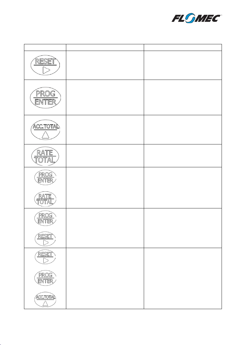
2.2 Keypad Function
KEY
FUNCTION IN OPERATING MODE
FUNCTION IN PROGRAM MODE
Press and hold for 3 seconds to
display to reset it
Each press progresses to the next
operating mode.
Press and hold to display the
accumulated total display.
reset the Total display to zero.
Total must be displayed on LCD
Press and hold to display the
software version (tag number is
displayed if enabled)
accumulated total. Holding this
key for 10 seconds will latch the
Toggles between the Rate and
Total displays
Press and hold both buttons
+
+
simultaneously for a duration of
5 seconds to enter the
programming mode
Press and hold PROG/ENTER and
then press RESET to toggle
between displaying software
version, serial number, and tag
number (if tag no. is enabled )
Selects the digit to be
incremented/edited, moves the
curser to the right.
program step.
Holding for 3 seconds will save all
program settings and exit to
Increments the selected digit
Moves one step backwards in the
program
No Function
No Function
+
+
Press and hold for 7 seconds to
perform a hard restart of the
software. To be used in the case
of ‘frozen’ software which may
be caused by user faults such as
short circuiting of the instrument.
*CAUTION*
Press and hold for 7 seconds in
Programming Mode to wipe all
settings from the device and
reset to factory default settings.
Record all important settings
before resetting the instrument.
7
Page 8

2.3 Operating Functions
2.3.1 Resettable Total
The display toggles between Rate and Total displays when the RATE/TOTAL key is pressed.
Pressing the RESET key and holding for a period of 3 seconds while the Total is displayed on
the LCD will cause the Total to reset to zero.
2.3.2 Accumulated Total
The Accumulated Total is displayed momentarily whenever the ACC.TOTAL key is pressed,
holding the key will hold the Accumulated Total display. If permanent display of the
Accumulated Total is required, this can be achieved by pressing and holding the ACC.TOTAL
key for a period of 10 seconds. Once this is done the Accumulated Total display will latch every
time the ACC.TOTAL key is pressed; to revert the Accumulated Total display to a momentary
display hold the ACC.TOTAL key again for 10 seconds.
The Accumulated Total display can only be reset by entering into the Programming Mode
and progressing to the Accumulated Total Reset function in the Advanced Menu. Protection of
the Accumulated Total reset can be achieved by PIN protecting the Programming Mode.
2.3.3 Rate Display
The Flow Rate Display is toggled by pressing the RATE/TOTAL key; Rate display remains
active until the RATE/TOTAL key is pressed again. The update frequency of the Rate display is
influenced by two parameters; the update frequency of the display (1Hz on battery power, 4Hz
on external DC or loop power), and the Rate Calculation Pulses parameter. If the update
frequency of the Rate Display is too slow consider reducing the number of pulses for the rate
calculation (see section 5.10). Conversely if it is required to stabilise an erratic Rate Display,
increasing the Rate Calculation Pulses parameter will achieve this.
Other parameters which influence the Rate Display are the Rate Damping, and Low
Frequency Cut-Off settings. Rate Damping will smooth out rapid changes in the flow rate in
order to maintain a steady display, however in systems where fast changes in the flowrate
must be displayed the Rate Damping parameter should be minimised.
The minimum input frequency requirement for a Rate Display is 0.2Hz with the factory
settings; this can be reduced to 0.1Hz by adjusting the Low Frequency Cut-off parameter. Note
that Totalisation is not effected by the Low Frequency Cut-off parameter.
8
Page 9

2.3.4 Display Backlight
The display backlight will be automatically enabled upon connection of an external DC
voltage supply in the range of 12-30V; the backlight is not available when operating on battery
or loop power. If it is required to reduce power consumption while operating on external DC
power the backlight can be overridden in the Advanced Menu (see section 5.10).
2.3.5 Analogue Output
The loop powered 4-20mA Analogue Output is a passive non-isolated output capable of
retransmitting the flowrate to remote instrumentation or control systems such as a PLC or
DCS. The Analogue Output can be spanned anywhere within the operating range of the
associated flowmeter; both the 4mA and 20mA points are software programmable in the units
selected for the Rate display. The instrument will over-range to 22mA which allows the user to
identify when the system is exceeding its maximum normal flowrate (i.e. identifying a fault
condition).
The Analogue Output accuracy is ±0.05% of Full Scale (0.01mA) at a regular ambient
temperature of 25
o
C. Due to the effects of temperature changes on the internal components,
the accuracy will become progressively worse as the ambient temperature moves further
away from 25
o
C; up to a worst case of ±0.25% of Full Scale (0.05mA) at the extremes of the
instrument’s operating range (-30oC or +80oC)
If required, the Analogue Output can be software adjusted to achieve the best accuracy
under the specific operating temperature of your installation. The 4mA and 20mA points are
both adjustable in 0.001mA increments by accessing the Analogue Output Adjustment section
of the Advanced Menu (see section 5.10 of this manual).
2.3.6 Unscaled Pulse Output
The Unscaled Pulse Output function is used to retransmit the input signal from the
associated flowmeter; it will maintain the same frequency and duty cycle as the input signal.
When setting up a system with two separate Total displays on two separate instruments the
Unscaled Pulse Output is the best method of transmitting the Total value to the secondary
totalising instrument.
The Unscaled Pulse signal can be transmitted as an NPN signal from the passive digital
output, or as an NPN or PNP signal from the isolated digital output. The passive digital output
can be used on battery power, however transmitting the signal via the isolated output will
require an external DC power supply.
9
Page 10

2.3.7 Scaled Pulse Output
The Scaled Pulse Output is used to transmit the totalised volume at a user selectable
resolution; this is programmed as a volume quantity per output pulse (e.g. 10Litres/Pulse or
100mL/Pulse). The frequency of the Scaled Pulse Output signal automatically adjusts according
to the input frequency and the scale factor, up to a maximum limit of 100Hz.
The Scaled Pulse signal can be transmitted in the same way as the Unscaled Pulse signal
above, either through the passive or isolated output.
The pulse width of the Scaled Pulse output is fixed at 300ms for output frequencies below
1.67Hz, however once above 1.67Hz the instrument adjusts the pulse width according to the
frequency to give a 50:50 duty cycle up to the maximum output frequency of 100Hz. Systems
should be designed to stay below the 100Hz limit, however if 100Hz is exceeded the
instrument will output at 100Hz and store any excess pulses in memory. Pulses stored in
memory will continue to output after the flow has stopped until the stored pulse count
reaches zero.
2.3.8 Alarm Output
Flow Rate Alarms may be programmed for High, Low, or High/Low; the digital output will
trigger when the registered flowrate passes the configured set-point(s). For a Low Alarm the
output will trigger once the flowrate drops below the set-point, a High Alarm will trigger with a
flowrate over the set-point, and a High/Low alarm will trigger if the flowrate is either over the
upper set-point or below the lower-set point.
Each set-point is configured with its own dead-band percentage which allows the user to set
a buffer zone (hysteresis) to avoid alarm “chattering” (switching quickly on-off-on-off) with a
flowrate hovering around the set-point. The dead-band setting is entered as a percentage of
the set-point value; e.g. a 5% dead-band with a 100L/min High Flow Alarm will trigger ON at
100L/min but will not turn OFF until the flow drops to below 95L/min.
Alarm Outputs can operate as an NPN signal via the passive digital output, or as a PNP or
NPN signal via the opto-isolated output. For relay switching be sure to follow the requirements
in the relevant wiring diagram in section 4.3.
2.3.9 Passive NPN Transistor Output
The passive NPN transistor output is the default method of transmitting the pulse or alarm
outputs, as it is the easiest and lowest cost solution where an NPN signal below 30VDC is
suitable. The passive NPN output shares a common ground inside the instrument, so may not
be suitable for installations requiring an analogue output in combination with a digital output,
as it may cause analogue signal issues due to the formation of a ground loop.
10
Page 11

The passive NPN output will function on battery power, however this will reduce the battery
life of the instrument by approximately 50%. For applications requiring an alarm output which
is not triggered often the effect on battery life is expected to be negligible.
Internal protection is provided for voltage spikes caused by switching inductive loads (relays,
solenoids, etc.) by fitment of an internal flyback (suppressor) diode to the passive NPN output.
No additional circuit components are required when triggering a DC relay or DC solenoid with
this output.
2.3.10 Isolated Digital Output
The Isolated digital output is provided by means of an Opto-Coupler, which provides a signal
with no electrical connections to the other internal circuitry of the instrument. The isolated
output should be used preferentially whenever a user requires both an analogue output and a
digital output (alarm or pulse signal) to a common receiving instrument; this will avoid the
creation of ground loops which interrupt the analogue signal. The isolated digital output is also
chosen whenever a PNP signal is required; the configuration of PNP vs. NPN is accomplished
via wiring which can be seen in the electrical installation section of this manual (section 4.3).
The isolated digital output is rated to 50V AC or DC, and 300mA; so should be used instead of
the passive NPN output for switching any loads greater than 30VDC or for switching any low
voltage AC loads <50VAC. The isolated digital output is not internally protected from voltage
spikes generated by inductive loads such as relays or solenoids, so a diode (1N004
recommended) should be fitted across any inductive DC loads as shown in section 4.3.5. For AC
relays or solenoids voltage spike protection should be provided by fitment of a metal oxide
varistor fitted in place of the diode (EPCOS SIOV-S05K50 or SIOV-S07K50 recommended).
Where the recommended diode or varistor is not available, a similar component of equivalent
specification may be used.
2.3.11 Battery Power
The instrument is powered by a Lithium Thionyl Chloride (Li/SOCl2) AA size battery which is
non-rechargeable. When operating under average conditions the instrument is expected to
have approximately 5 years of battery life; average conditions are considered to be a reed
switch input from a Flomec flowmeter with no outputs used. High input frequencies (~1kHz
and higher) from a turbine flowmeter will reduce battery life by around 20%, and operation of
a battery powered scaled pulse output will reduce battery life by approximately 50%. When
the NPN transistor is used for an alarm with infrequent operation the reduction of battery life
may be negligible.
11
Page 12

A low battery is indicated by the battery symbol on the lower line of the LCD display;
illumination of this indicator shows that the battery should be replaced as soon as possible.
Generally the remaining battery life after low battery indication is several days however this is
not guaranteed. Replacement batteries are available from the instrument manufacturer or
they may be purchased independently by the user; for user replacement it is recommended
that a Tekcell SB-AA11 battery be used. Use of a battery which is not a 3.6V Lithium Thionyl
Chloride type will void the instrument warranty.
2.3.12 External DC Power
External DC power may be connected to the instrument in the range of 12-30V DC; this will
activate the LCD backlight, the sensor supply, and the isolated output. When external DC
power is provided the instrument will no longer draw any power from the battery – the
battery will then only be used as a backup power source. With the battery in backup mode the
life is expected to be approximately 8-10years.
2.3.13 Sensor Supply
The instrument is equipped with a regulated sensor supply (5V/20mA maximum) terminal
which is suitable for powering hall-effect sensors in Flomec flowmeters. The sensor supply is
only available when the instrument is connected to an external 12-30V DC supply, it is not
available under loop power. 20mA of sensor current is available when the external DC supply is
24V or higher; Flomec flowmeters will only require 12V DC supply to the instrument.
12
Page 13

3. Mechanical Installation
3.1 General Requirements
Installation of this product should only be carried out by suitably qualified/trained personnel
with an understanding of local regulations regarding electrical installations, and if relevant
Hazardous Area electrical installations.
It is recommended that the instrument is installed in a location where it is shielded from
extreme varying weather conditions, and from chances of physical impact. Never install the
instrument in an area which will expose it to temperatures outside its specified operating
temperature range.
3.2 Conduit Entries
Each instrument is equipped with three conduit entries which are factory sealed to maintain
the IP rating of the enclosure. To gain access to a conduit entry the integral moulded plug must
be broken out of the electrical entry. Inserting a suitably sized screw driver or Allen-key into
the centre of the conduit entry plug and bend the plug back and forth until it breaks away
from the enclosure.
Always use IP rated cable glands when fitting cable to the instrument. If any electrical
entries are opened using the method above and are later not used, these must be sealed using
a threaded conduit plug with an appropriate IP rating (IP66 or IP67 is recommended)
3.3 Integral Meter Mounting
This instrument may be purchased as a meter mount display which will mount on the top of
any Flomec flow meter. For any instruments purchased as field mount, these may be
converted to a meter mount instrument by purchasing a new rear enclosure.
Likewise for mounting of instruments on flowmeters with a process temperature of over
o
80
C there is a ‘Cooling Fin Kit’ available from the manufacturer which will allow this; these
may be retro-fitted in the field with minimal effort.
13
Page 14

3.4 Wall and Pipe Mounting
Panel mount
Cut a 106.5mm (4.2 ”)
Mounting of the instrument in a panel
42.6 mm
( 1.67
18 mm
( 0.7
96 mm ( 3.8 ” )
Mounting of the instrument on
a pipe or flat surface (such as a
wall) can be accomplished using
the ‘Wall Mount Kit’, or ‘Pipe
Mount Kit’ available from the
manufacturer.
3.5 Panel Mounting
requires a 106.5mm – 107.8mm (4.20” -
4.25”) round hole to be cut in the panel.
Up to a 109mm (4.30”) is suitable if the
IP65 rating is not required.
The rear enclosure of the instrument can
be mounted behind the panel (as per
diagram to the right) to protect the back of
the electronics module if required,
however this is not compulsory.
When panel mounted the IP rating of the
instrument is reduced to IP65 on the front
side of the panel only – with the rear
enclosure mounted behind the panel the
back side of the instrument will have an
IP20 rating.
” )
” )
diameter hole in panel
14
Page 15

4. Electrical Installation
All wiring connections should be made with good quality shielded instrument cable; wiring
between terminals which are inside the instrument enclosure, or between a flowmeter and an
integrally mounted instrument may use non-shielded wire. Cable shields or drain wires should
be connected to the instrument ground (GND) at the instrument end only – isolate the
shield/drain wire at the flowmeter end of the cable.
The terminal connections on the instrument will allow for usage of wiring up to 2.5mm
section (14AWG) – if two wiring connections into the same terminal are required the
maximum cross section of each wire is 0.75mm2. Wire insulation should be stripped to a length
of 6.5mm and conductors should be fitted to the terminals so that there is minimal exposed
conductor. Terminals can be tightened with a No.1 Phillips head screwdriver, or a 3mm or 1/8”
flat blade screw driver.
4.1 Terminal Identification
The terminal connections are divided into 4 separate sections by their function; all input
terminals are on the left and all output terminals on the right - see below for more detail.
There is a separate ground (GND) terminal in each section of terminals; as this instrument has
a common ground, all GND terminals are internally connected.
2
cross
15
Page 16

4.2 Input Connections
The input type must be set in the software before the below wiring connections will function
4.2.1 Reed Switch Input
4.2.2 NPN Sensor Input (Hall Effect)
16
Page 17

4.2.3 PNP Sensor Input
4.2.4 Voltage Pulse Input (Wiegand Sensor / DP Meters)
17
Page 18

4.2.5 VR Coil Input (Turbine Meters)
4.3 Output Connections
4.3.1 Passive NPN Digital Output with Unpowered Sensor
Notes: Shown here with Reed Switch input, Coil and Voltage Pulse inputs also suitable for this
configuration. *External 12-30V DC power supply to instrument is optional.
18
Page 19

4.3.2 Passive NPN Digital Output with Powered Sensor
4.3.3 PNP Digital Output – configuration suitable for all input types
19
Page 20

4.3.4 Digital Output to a Relay – Recommended connection for all 12-30V DC Relays
Note: Wiring connection from voltage supply to +24V terminal on instrument is not
compulsory, however it will prolong battery life.
4.3.5 Digital Output to a Relay – For up to 50V DC and 50V AC Relays
Note: This output type is not internally protected from voltage spikes from inductive loads, a
diode must be fitted as shown for DC loads, or a Metal Oxide Varistor fitted for AC circuits.
20
Page 21

4.3.6 Analogue Output with an Unpowered Sensor – Negative Reference
Notes: Shown here with Reed Switch input, Coil and Voltage Pulse inputs also suitable for this
configuration.
4.3.7 Analogue Output with an Unpowered Sensor – Positive Reference
Notes: Shown here with Reed Switch input, Coil and Voltage Pulse inputs also suitable for this
configuration.
21
Page 22

4.3.8 Analogue Output with a Powered Sensor – Negative Reference
4.3.9 Analogue Output with a Powered Sensor – Positive Reference
Note: Some instrumentation systems may have a common ground between the analogue input
and the DC supply, for those systems this wiring configuration will not be possible and
configuration 4.3.8 must be used.
22
Page 23

4.4 Connections for Combined Outputs
4.4.1 Combined Analogue Output and NPN Digital Output to Common Receiver
4.4.2 Combined Analogue Output and PNP Digital Output to Common Receiver
23
Page 24

5. Programming Parameters
Total Unit
Rate Unit
Density
Conversion Factor
Kilograms
Litres
1200kg/m3 1.200
Litres
Kilograms
1200kg/m3
0.833
US Barrels (none)
Gallons
N/A
42.000
5.1 PIN Program Protection
Any user defined PIN other than 0000 will engage the program protection mode; after the
PIN protection mode is enabled failure to input the correct PIN number will deny the user the
ability to change any of the program parameters, but will allow read only access to the user so
that they may view existing program settings.
Only one PIN may be set at any one time, but this can be changed at any time by entering the
programming mode, entering the existing PIN, and then changing the PIN to a new number. A
second backup PIN exists in the software which can be used should the user programmed PIN
be lost – contact the manufacturer should you require the backup PIN.
5.2 Engineering Units
The engineering units for the instrument may be selected from any of the following; Litres,
millilitres, cubic Metres, kilograms, Gallons, Quarts, Pounds, or none. The unit ‘none’ is used
where the user requires a unit other than those available and the number of pulses / unit are
known for the required unit – for example US Barrels can be used by selecting the units as
‘none’.
The Total and Rate units are programmed separately, and may be selected as separate units,
for example millilitres for total, and L/hr for the flowrate. When the selected Total unit and the
selected Rate unit are both units of volume, or are both units of mass (e.g. Litres and Gallons,
kilograms and pounds) the instrument will calculate the difference without further user input.
However when the units are a mixture of volume and mass, the user must enter their own rate
conversion factor.
5.2.1 Rate Units Conversion
The Rate Conversion Factor is calculated as the quantity of Rate units per Total unit – see the
following chart for some examples:
5.3 Time-base for Rate
The time-base for the Rate display may be selected from any of the following; units/second,
units/minute, units/hour, units/day. The Rate time-base setting with determine the units used
in programming the analogue output set points.
24
Page 25

5.4 Decimal Places
Software
Setting
Maximum
Frequency
OM Meters
DP Meters
OM Meters – Hall Effect
EGM Meters – Hall Effect
Other manufacturer’s
Flow Meters
Variable Reluctance Coil
Turbine Flowmeters
Coil
2kHz
Wiegand Sensor
DP Meters - Voltage Pulse
Coil
2kHz
Decimal places are separately adjustable for Total, Accumulated Total, and Rate from zero to
three decimal places. The decimal places setting for Rate will set the available decimal places
in the analogue output set point. The decimal place settings for Total and Accumulated Total
do not influence configuration of the pulse output.
5.5 K-Factor Entry
The K-factor entry screen allows entry of up to 7 whole numbers and 4 decimals, however
only the first 7 significant digits are used by the software in calculating totals. When entering
the K-factor screen not all available digits are shown; moving the curser to the right will show
the remaining available digits. Note that when different engineering units are configured for
Total and Rate, the K-factor should be entered in the engineering units which are selected for
Total.
5.6 Input Type Configuration
The input type can be selected from the following; Reed switch, NPN, PNP, or Coil. The
following table should be referenced when selecting the correct software setting for your
flowmeter. Instruments delivered integrally mounted to a flowmeter will have this
parameter factory set and do not require user adjustment.
Sensor Type Used in:
Reed Switch
NPN Sensor
PNP Sensor
5.7 Non-Linearity Correction
Non-linearity correction (NLC) allows the instrument to correct for known inaccuracies in a
flow-meter, thereby improving the overall measurement accuracy, and in many cases
increasing the effective flow range of the measurement system. Non-linearity correction can
be used on battery power however battery life will be reduced according to usage.
DP Meters – Hall Effect
25
REED 120Hz
NPN 1.2kHz
PNP 1.2kHz
Page 26

Non-linearity correction functions as an intermediate process between the receiving of input
pulses and the calculation of totals; therefore all subsequent processes such as Rate
calculation, analogue output calculations, and pulses/alarm outputs are also corrected
according to the settings programmed for the non-linearity correction.
The non-linearity correction function is programmed using up to 10 frequency points, and a
K-factor for each frequency point. Not all 10 points must be used, however a minimum of 2
points is required. Below the minimum frequency point the instrument will use the K-factor
entered for the lowest point, similarly above the maximum frequency point the instrument will
use the K-factor entered for the highest point. Linear interpolation is used between frequency
points.
If any frequency in the programming menu is entered as zero Hz then all remaining
frequency points will be disabled; i.e. if data is entered for points ‘0F’ to ‘4F’ and point ‘5F’ is
entered as 0Hz, points ‘6F’ to ‘9F’ will not be used. Once the non-linearity correction function
is enabled the general K-factor entered at Level 5 of the program is disabled; if the nonlinearity correction is later disabled the instrument will revert to the general K-Factor.
Data for entry of Non-Linearity Correction is available for Flomec meters when purchased
with a multi-point factory calibration. Alternatively NLC data can be obtained with a field
calibration of the meter.
5.8 Digital Output
The digital output function is configurable for either a pulse output according to totalised
flow, or an alarm output according to flowrate. The pulse output can be configured for an
unscaled pulse or a scaled pulse, and the alarm can be configured for notification of high
flowrates, low flowrates, or a combination of both.
5.8.1 Un-Scaled Pulse
The unscaled pulse output, also commonly referred to as a ‘repeater pulse’ is enabled by
selecting ‘UNSCALED’ in the digital output configuration menu.
5.8.2 Scaled Pulse
The scaled pulse output is enabled by selecting ‘SCALED’ in the digital output configuration
menu. Configuration of this output is accomplished by entering the number of units per output
pulse; e.g. 10 Litres/pulse, 0.1kgs/pulse, etc. The engineering units configured for the Total
display are used to specify the settings for this output. The range of available settings for this
output are from 0000.01 units/pulse up to a maximum of 9999.99 units/pulse.
As there is a frequency limitation on the scaled pulse output of 100Hz it is preferred to
configure the scaled pulse output to keep the output frequency below this limit. If it is
necessary for the scaled pulse output to operate at greater than 100Hz the instrument will
26
Page 27

output the signal at the maximum of 100Hz, and all excess pulses will be stored in memory
until such a time that flow has stopped and the instrument can output the stored pulses – it is
not recommended that systems be designed to operate in this way under normal conditions.
The output frequency can be calculated as follows:
=
If the system design does not allow significant periods of zero-flow where the instrument can
reduce the stored pulse count to zero it is advisable to increase the number of units/pulse in
order to keep the output below 100Hz.
5.8.3 Flow Alarm
The Alarm output is enabled by selecting ‘ALARM’ from the digital output configuration
menu. The alarm output may be configured as a ‘High Alarm’ which will trigger in the event
the flow rate exceeds the alarm set-point, a ‘Low Alarm’ which will trigger in the event the
flow rate drops below the set-point, or a ‘High/Low Alarm’ which is a combination of the two.
Configuration of the Alarm involves selecting the type of alarm, entering the alarm set-point
(specified in Rate units, e.g. L/min), and entering the alarm dead-band. The Alarm dead-band is
an adjustable buffer zone around the set point which provides hysteresis to the system, and
allows the user to overcome alarm chattering when the flowrate is fluctuating around the setpoint. The dead-band setting is entered as a percentage of the set-point value; e.g. a 5% deadband around a 100L/min High Flow Alarm will trigger ON at 100L/min but will not turn OFF
until the flow drops to below 95L/min.
( ) 60( )
( )
5.9 Analogue Output
The 4-20mA analogue output can be configured anywhere within the operating range of the
connected flowmeter; a 22mA over-range is provided for identification of flows exceeding the
maximum flowrate of the connected flow meter.
The output is configured in flowrate units for the zero point (4mA) and the full scale point
(20mA). The decimal places allowed for the set points are equal to the decimal place
configuration of the Rate display. The 4mA and 20mA points may be entered upside-down, i.e.
a 20mA point lower than the 4mA point. For information on testing or adjustment of the 4-
20mA signal see section 5.10.5 below.
27
Page 28

5.10 Advanced Menu
5.10.1 Resetting Accumulated Total
Resetting the accumulated total can only be done at this level of the Advanced Menu; by PIN
protecting the instrument it is possible to remove the ability of an operator to reset the
accumulated total. Once the accumulated total is reset it is not possible to recover the value
which was in the accumulated total – it is advisable to record the accumulated total value
before resetting.
5.10.2 Rate Damping
Flow Rate Damping is used to smooth out fluctuating flow input signals in order to provide a
stable Rate Display and Analogue Output. Most input signals are reasonably stable and need
only the default Rate Damping setting, however for systems with large flow fluctuations the
Rate Damping setting may need to be increased.
If the user requires quick visual indication of changes to a system’s flowrate (either on the
Rate Display, or in the Analogue Output) this can be accomplished by reducing the Rate
Damping setting. To remove all damping from the flow rate calculation Rate Damping can be
set to zero.
5.10.3 Low Frequency Cut-Off
The low frequency cut-off parameter is used to adjust the minimum frequency required for
the rate display and analogue output functions. This setting is useful to avoid spikes in the rate
display and analogue output from “apparent flow” which could be caused by movement of
liquid in the pipes of a mobile installation (on a truck etc.), pulsations from a dead-headed
pump, etc.
The default value for the low frequency cut-off is 0.2Hz, and the parameter is adjustable
from 0.1Hz up to 9.9Hz. It is not possible to enable a rate display or analogue output for input
frequencies below 0.1Hz.
5.10.4 Rate Calculation Pulses
The purpose of the ‘Rate Calculation Pulses’ parameter is to determine the number of input
pulses which are used in calculation of the flow rate; the more pulses which are used the more
accurately the Rate Display will represent the average flow-rate of the system. The parameter
is adjustable from 1 to 255 pulses per calculation. For systems using pumps with a nonuniform rate of delivery (piston pumps or similar) it is important to have a high value for this
parameter as it will produce a stable rate display and analogue output which is representative
of the average flow through the pipe.
For systems with a steady and uniform flow through the pipe, lower values can be used for
this parameter in order to achieve a more responsive rate display and analogue output.
28
Page 29

However it should be kept in mind that for any battery powered applications, using a value
lower than the default will decrease battery life.
5.10.5 Analogue Output Adjustment
The analogue output may be adjusted/trimmed at this level of the program; this should not
be necessary in most applications as the analogue output is factory calibrated, however it may
be useful when operating at extreme ambient temperatures.
There are two parameters which the user can set; the 4mA adjustment and the 20mA
adjustment. With the 4mA adjustment showing on the instrument display the unit will output
4mA to the receiving instrument, likewise with the 20mA adjustment showing on the display
the unit will output 20mA. By noting the difference in the receiving instrument’s reading in mA
the user can correct any errors.
The display allows entry of the adjustment in 0.001mA steps, and adjustments may be made
in the positive or negative direction. The default adjustment direction is positive, however
this can be changed by holding the ‘UP arrow’ key for 3 seconds.
5.10.6 Backlight Override
The backlight is automatically enabled whenever external DC power is connected to the
instrument; this feature may be over-ridden in this level of the program. The backlight
override may be set to ‘ON’ (normal function), ‘OFF’ (always off), or ‘INT’ (intermittent, the
backlight will be on for 30 seconds following a button press). Note that ‘INT’ operation still
requires external DC power.
5.10.7 Tag Number Entry
The user may enter an identifying tag number into the instrument, according to the P&ID of
the installation where it is used. The default tag number is FIT-000 allowing quick entry of a
simple ISA-5.1 standard Tag Number, however this can be expanded up to 12 digits of
alphanumerical characters and hyphens (e.g. FIT-123-45AB). The leading 3 digits (FIT;
describing the device as a Flow Indictor/Transmitter) may also be changed to any
alphanumeric character to suit the user’s requirements.
Once a tag number is entered it is viewed during the operating mode by pressing and holding
the PROG/ENTER key; when the tag number contains more than 8 digits it will scroll across the
LCD.
29
Page 30

6. Programming Flowchart
30
Page 31

31
Page 32

32
Page 33

7. Program Detail Record
User PIN
Total
Rate
Rate Conversion Factor
Yes No
RCF =
Time Base for Rate
/Sec /Min
/Hr /Day
Total
0
0.0 0.00 0.000
Accum. Total
0
0.0 0.00 0.000
Rate 0 0.0 0.00 0.000
K-Factor (pulses / unit)
K =
Input Type
Reed
Coil NPN PNP
Non Linearity Correction
Yes No
Point 0F
Hz
K =
Point 1F
Hz
K =
Point 2F
Hz
K =
Point 3F
Hz
K =
Point 4F
Hz
K =
Point 5F
Hz
K =
Point 6F
Hz
K =
Point 7F
Hz
K =
Point 8F
Hz
K =
Point 9F
Hz
K =
Digital Output
Yes No
Digital Output Type
Unscaled
Scaled
Alarm
Units per Output Pulse
N/A
Alarm Set-Point
High:
Low:
Alarm Dead-Band
DB%:
Analogue Output
Yes No
Zero Set-Point (4mA)
4mA@
Full Scale Set-Point (20mA)
20mA@
Rate Damping
Low Frequency Cut-off
Rate Calculation Pulses
Backlight Setting
Tag Number
Engineering Units
Decimal
Points
33
Page 34

8. Spare Parts
Description:
Includes:
Part No:
Bezel Cover
1 x Bezel Cover
1306014
Complete replacement front housing with clear
lens and keys. Facia not included
Rear housing for meter mounted instrument
fasteners and seals for meter mounting
Rear housing for meter mounted instrument
fasteners and seals for meter mounting
Field Mount Rear
Housing Kit (M20)
Rear housing for field mounted instrument (M20
electrical entries)
Field Mount Rear
Housing Kit (NPT)
Rear housing for field mounted instrument (NPT
electrical entries)
All internal and external fasteners, including
meter mount screws.
Housing Seal
BS046 Buna-N (Nitrile) O-Ring
BS046B
Facia Sticker
(Decal)
Safe Area Battery
3.6V AA Lithium Battery
1312035
Tekcell SB-AA11
Tadiran TL5903/S
Spare parts for your instrument are available from the local dealer or national distributor
from whom you purchased the instrument; see spare parts list below to determine which
parts numbers you require.
Front Housing Kit
Meter Mount Rear
Housing Kit (M20)
Meter Mount Rear
Housing Kit (NPT)
Fastener Kit
Alternative Replacement Battery for Safe Area Units Only
Note: Use of a battery which is not a 3.6V Lithium Thionyl Chloride type will void the
instrument warranty.
(M20 electrical entries). Includes the required
(NPT electrical entries). Includes the required
Self-adhesive facia (decal) with Flomec logo 1315147
1502058
1502001
1502002
1502003
1502004
1508128
34
Page 35

Notes:
35
Page 36

9. Manufacturer’s Declaraon
We, Trimec Industries Pty Ltd, of Sydney Australia, trading as Great Plains
Industries Australia or ‘FLOMEC’
Declare under our sole responsibility that the RT14 Rate Totaliser is in conformance with
the following European direcves:
2014/30/EU EMC Direcve
Conformity is declared under the following standards
EN61000-6-2:2005
Electromagnec compability (EMC).Generic standards. Immunity for industrial
environments
EN61000-6-3:2007
Electromagnec compability (EMC). Generic standards. Emission standard for
residenal, commercial and light-industrial environments
EN61326-1:2013
Electrical equipment for measurement, control and laboratory use. EMC
requirements. General requirements
2011/65/EU RoHS Direcve
Conformity is declared under the following standards
EN50581:2012
Technical documentaon for the assessment of electrical and electronic products
with respect to the
Mahew Wyres, Sydney, Australia
Engineering Manager 21/05/2016
Trimec Industries Pty. Ltd.
RT14 Instrucon Manual IM-RT14-2116
restricon of hazardous substances
 Loading...