

Page 1

CL800
Free Chlorine & pH Monitor
OPERATION GUIDE
Page 2

CONTENTS
1.
INTRODUCTION…..…………………………………..….……..
2
2.
FEATURES AND TECHNICAL SPECIFICATIONS……….
…
2
2.1
Features..…………………………..……………...………..
2
2.2
Technical Specifications……...…………….…………......
2
3.
INSTALLATION…….…………………………..………..………
3
3.1
Dimension………………...……...…………………..……..
4
3.2
Connection.…………….……..………..…….....….………
4
4.
SETTING AND OPERATION…..…………...…….……………
6
4.1
User Interface and Description………………….........…..
6
4.2
Parameter Setting and Operation.……..…..….……...…..
7
4.2.1
Password…………………………………………………….
9
4.2.2
Main Setting Menu Directory………………………………
10
4.2.3
Set Parameter……………...……………………………….
10
4.2.4
Set Alarm………….……………...…………………………
14
4.2.5
Set Current Output………...…..……………..…………….
17
4.2.6
Calibration……………….…………..……..……………….
18
4.2.7
Save and Read Data………….………..…………………..
23
4.2.8
Restore Factory Setting.…………………..……………….
26
5.
SENSOR…….……………………………….…..……………….
27
6.
WARRANTY……...………………………………………………
30
7.
STANDARD CONFIGURATION…..…………………..……….
30
8.
OPTIONAL CONFIGURATION…………..………...…….…….
30
1
Page 3

CL800 Intelligent On-line Free Chlorine & pH Monitor
1. INTRODUCTION
The CL800 is a microprocessor controlled Free Chlorine and pH
measurement instrument. The unit utilizes a multifunction LCD to display
readings and provide feedback to the user. It is available with different
option to provide fully configurable control, alarm and feedback with up
to four relays and two 4-20mA current output sources. It can be used to
detect the Free Chlorine and pH value of the solution in chemical,
petroleum, rubber, paper, tobacco, alcohol, sugar, food, mining,
smelting, iron and steel, power generation, pharmaceuticals, water
treatment and other industries.
2. FEATURES AND TECHNICAL SPECIFICATIONS
2.1 Features
(1) Large back-lit multifunction LCD display
(2) Wall or Panel mounting is available
(3) Man-machine interface is friendly
(4) Measured process Free Chlorine, pH, temperature
(5) 0 ~ 100℃ automatic/manual temperature compensation for pH
(6) Manual or Automatic buffer adjustment
(7) Restore factory setting function is available
(8) ROM inside, measurements and time can be programmed store
(9) Galvanic separation between inputs and outputs and supply voltage
(10) Different input for excellent noise rejection
(11) High and low programmable alarm, 250V/10A relay output
2.2 Technical Specifications
(1) Ranges of measurement:CL: 0~2ppm、0~5ppm、0~10ppm
PH: -1.00~15.00 pH
2
Page 4
Temp: 0~100℃
(2) Accuracy:±0.5 %F.S ppm / ±0.2 %F.S PH / ±0.2℃
(3) Linearity:±0.5% of range
(4) Repeatability:±0.5% of range
(5) Temperature compensation type:Auto / manual 0℃ to 100℃(for
pH)
(6) Alarm Output:Four relays outputs (250V/10A),full range with
hysteresis adjustable
(7) Current output:Two DC 4~20mA,Opto-isolated outputs,( 750Ω Max.
load)
(8) Ambient Operating temperature:-10~+55℃
(9) Humidity:≤95%
(10) Power supply:AC100~240V,50~60Hz
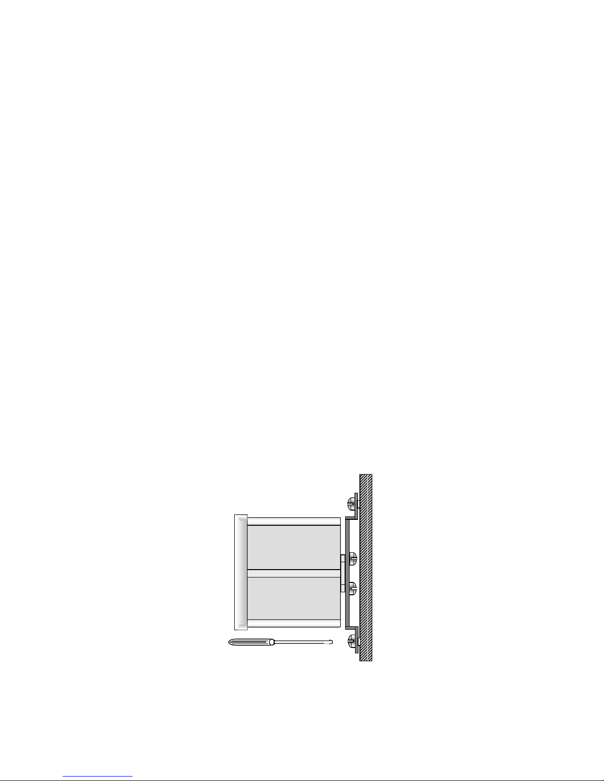
3. INSTALLATION
Depending on the installation position, use the attached mounting
bracket and fastened it horizontally or vertically on the rear of the
instrument with screws, then fixed on the wall or panel as figure 1.
3
Figure 1 : installation diagram
Page 5
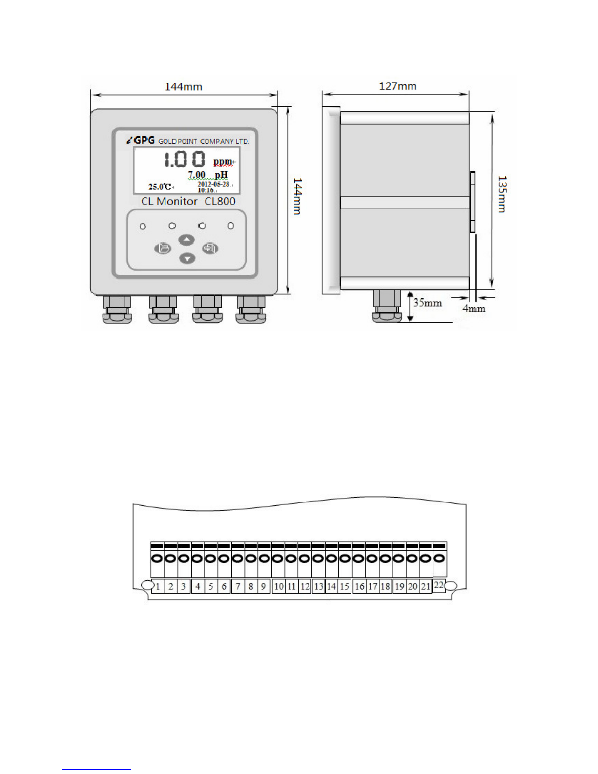
3.1 Dimensions
3.2 Connection
Remove the four bolts on the front of the instrument, open the case
gently, you can see a row of terminals shown in Figure 3, please wiring
follow the directions.
Connection terminals wiring directions:
1. PH+, pH sensor central line (+)
2. PH-, pH sensor shield (-)
4
Figure 2 : overall dimensions panel-mounting
Figure 3 : connection terminals diagram
Page 6

3. CL+, Free Chlorine sensor central line (+) <Red>
4. CL-, Free Chlorine sensor shield (-) <Black>
5. T1, Pt 100 temperature sensor(1)
6. T2, Pt 100 temperature sensor(2)
7. CLI-, 4~20mA current output for Free Chlorine (-)
8. CLI+, 4~20mA current output for Free Chlorine (+)
9. PHI-, 4~20mA current output for pH (-)
10. PHI+, 4~20mA current output for pH (+)
11. CLL1, Free Chlorine low alarm relay output (N/O, normally open)
12. CLL2, Free Chlorine low alarm relay output (Common)
13. CLH1, Free Chlorine high alarm relay output (N/O, normally open)
14. CLH2, Free Chlorine high alarm relay output(Common)
15. PHL1, pH low alarm relay output (N/O, normally open)
16. PHL2, pH low alarm relay output (Common)
17. PHH1, pH high alarm relay output (N/O, normally open)
18. PHH2, pH high alarm relay output(Common)
19. QX1, cleaning relay output (N/O, normally open) <Optional>
20. QX2, cleaning relay output (Common) <Optional>
21. Power supply terminal: Connect AC100 ~ 240V
22. Power supply terminal: Connect the power supply phase
★
CAUTION ! :
The specified performance of the CL800 is entirely dependent on correct
installation. For this reason, the installer should thoroughly read the
instructions before attempting to make any electrical connections to the
unit.
5
Page 7
4. SETTING AND OPERATION
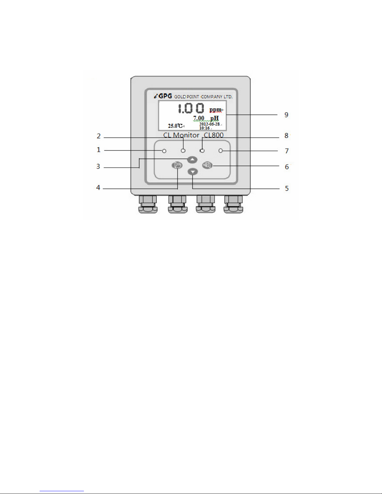
4.1 User Interface and Description
Front panel description:
(1) CL alarm light,Under the conditions of setting Free Chlorine high or low
alarm, when the measured Free Chlorine value of the solution is
higher than the value of High alarm or lower than the value of Low
alarm, the CL alarm light will be turned on.
(CL high alarm light when only CL measuring)
(2) PH alarm light,Under the conditions of setting pH high or low alarm,
when the measured pH value of the solution is higher than the value
of High alarm or lower than the value of Low alarm, the PH alarm light
will be turned on.
(CL low alarm light when only CL measuring)
(3) UP key. In the setting state, using the UP key the user can cycle
through the front menu. To adjust a value, the UP key is used to
6
Figure 4: front panel diagram
Page 8

Figure 5 measurement state 1
increment the digit.
(4) MENU switch. Press this key to enter or exit the setting state.
(5) DOWN key,In the setting state, using the DOWN key the user can
cycle through the next menu. To adjust a value, the DOWN key is
used to select a digit.
(6) ENTER key is the enter button to confirm enter the menu and store
the setting parameters.
(7) Meas indicator light, the light will be turned on when entering the
measuring state.
(8) SET indicator light, the light will be turned on when entering the
setting state.
(9) LCD digital Monitor , displayed the measured values ( Free
Chlorine、pH、℃),and can also be displayed prompt function,
parameter values and error codes in interactive. (When measure
Free Chlorine only, pH will be displayed “none”, and temperature will
be displayed “25 ”℃ )
4.2 Parameter Setting and Operation
When the instrument is powered security, after a brief self-test program,
Meas indicator lights and screen display the Free Chlorine value, pH
value, temperature and time simultaneously as Figure 5. Indicates that the
instrument is working in the measurement state.
7
Page 9
Instrument has two kinds of operating states: "Measuring" state and
"Setting" state. In the measuring state, there are two kinds of display:
“only Free Chlorine” and “Free Chlorine & pH” display status. Generally,
when the instrument is powered on, it enter into the measuring state. Use
the MENU key to switch the "Measuring" state or "Setting" state. Press
MENU key in the measuring state, it will enter the setting state, and the
SET indicator light will be turned on. At this point press the UP or DOWN
keys to select various setting functions, press the MENU key to return to
measuring state.
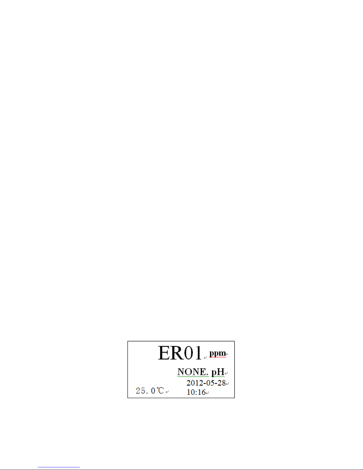
If there is an error code “ER01” display on the position of measurement
reading as Figure 6, indicated the Free Chlorine value is lower than
measuring range. (In the case electrode unused for more than two hours,
it need activation for period of time, during which the meter readings will
be displayed “ER01”)
If there is an error code “ER02” displayed, indicated the Free Chlorine
value is higher than measuring range.
If there is an error code “ER03” displayed on the position of the
temperature, indicated that there is no temperature input signal.
If there is an error code “NONE” displayed in front of pH, indicated that
there is no pH input signal.
Figure 6 measurement state 2 (error code)
8
Page 10
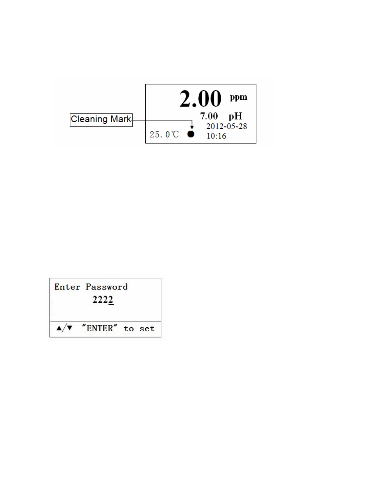
Instrument has the indication of cleaning function (optional) on the screen.
When the cleaning function is opened, there is a “●” mark on the screen
as Figure 7. When cleaning function stopped, cleaning mark disappear.
Figure 7 measurement state 3 (cleaning state)
4.2.1 Password
The CL800 Monitor is locked to prevent unauthorised access to the
configuration menu’s by using a password. If you want to enter the
setting menu, you must enter correct password.
The user password is a 4 digit number that can be set to any value the
user chooses. When press the MENU key, the screen will display:
When supplied new, the user password is set to 2223, we recommend that
this is changed when the instrument is installed. Use UP and DOWN to
modify it, then press ENTER to enter the main setting menu.
*Note: The factory default password is 2223, if the password has been
forgotten please contact Goldpoint technical support.
9
Page 11

4.2.2 Main Setting Menu Directory
Figure 8 main setting menu directory
After entering into the setting menu, the main menu is displayed on the
screen as Figure 8. By pressing the UP and DOWN keys to select menu
option, then press the ENTER key to enter this menu subdirectory.
4.2.3 Set Parameter
10
Page 12

4.2.3.1 Set Free Chlorine Measuring Range
Select “Set CL Range”, press
ENTER key to enter the next menu
level.
When the character starts flashing,
press DOWN key to select the digit,
the UP key is to modify the selected
digit. After modifying the value,
press ENTER key to save and
return to the previous menu.
※ This value must be equal to the measurement range of the
chlorine electrode.
4.2.3.2 Set CL-PH Compensation Mode
Press UP and DOWN keys to switch
"ON / OFF", press ENTER to
confirm.
Because chlorine value changes is affected by PH value changes, So
when the PH value is higher than 8.00pH or lower than 6.00pH, it need to
set CL-PH Compensation to "ON".
4.2.3.3 Set PH-Temperature Compensation
(
This function is disabled when Free Chlorine only)
11
Page 13

CL800 has Auto and manual temperature compensation function. Use
manual temperature compensation, according to the manual input
temperature value to compensate. Use automatic temperature
compensation, according to the measuring temperature value by the
temperature sensor to compensate.
Press UP and DOWN keys to select
“Auto” or “Manual”, press ENTER
key to confirm.
When selected temperature compensation mode to manual, you need to
enter the temperature value. Range is 0~100℃, and the factory default is
25.0℃.
The temperature compensation coefficient is different for each type of
solution, so the temperature compensation coefficient is designed to be
adjustable(25 ℃ as the reference), and the range is -2~+2%/℃. The
temperature compensation coefficient works both in automatic and manual
12
Page 14

ε
= ×100%
pH35-pH25
temperature compensation.
The Calculation Method of coefficient
*Remark:pH25=the pH value at t=25℃;pH35=the pH value at t=35℃
4.2.3.4 Modify Time and Date of Instrument
When the character starts flashing,
press DOWN key to select the digit,
the UP key is to modify the selected
digit. After modifying the value,
press ENTER key to save and
return to the previous menu.
Method of modify date is similar to
modify time.
4.2.3.5 Change Password
When the character starts flashing, press DOWN key to select the digit,
the UP key is to modify the selected digit. After enter a new password,
press ENTER key to save and return to the previous menu.
13
pH25
*(35
-
25)
Page 15

4.2.3.6 Set Cleaning for the Sensor
Press UP and DOWN keys to switch
"ON / OFF", press ENTER to confirm.
Only when it sets to "ON", in order to
proceed to the next setup menu.
Set Clean Duration, the unit is “S”
(second).
Set Clean Interval, the unit is “min”
(minute).
*Note: " Clean Duration " and " Clean Interval " can not both be set to 0.
Sensor cleaning equipment is the optional configuration, please confirm
the device are connected correctly before set cleaning to “ON”.
4.2.4 Set Alarm
The CL800 monitor has four alarm outputs designated high alarms(H)
14
Page 16

and low alarms(L). The alarm value and alarm hysteresis can be set
within the currently selected measuring range.
Alarm Relay
During normal operation when the alarm is not active, the alarm output
will be in its NORMAL condition, the N/O (normal open) contact will be
open. When the alarm is active, the alarm output will be in its ALARM
condition and therefore the N/O contact will be closed.
Alarm Hysterisis
In a normal condition an alarm turns on and off at the same value. For
example, if a high alarm turns on at 10.00pH the alarm occurs when the
reading increases to 10.00pH. When it decreases through 10.00pH the
alarm turns off.
Some applications may demand that the alarm turns off at a different
value, for a high alarm this would be value lower than the alarm value,
and for a low alarm this would be a value higher than the alarm value.
The hysterisis value determines the difference between the alarm switch
on point and the alarm switch off point. In the case of a high alarm,
hysterisis causes the alarm to turn off at a value that is less than the
alarm value. For a low alarm, hysterisis causes the alarm to turn off at a
value greater than the alarm value.
15
Figure 9 alarm with hysterisis
Page 17

Select “Set Alarm”, press ENTER key to enter the next menu level.
Press UP and DOWN keys to select the item you want to modify, then
press ENTER to enter into. When the character starts flashing, press
DOWN key to select the digit, the UP key is to modify the selected digit.
After modifying the value, press ENTER key to save and return to the
previous menu. The factory default alarm value as below:
CL H Alarm 2.00 ppm PH H Alarm 13.00 pH
CL H Hysteresis 0.01 ppm PH H Hysteresis 0.10 pH
CL L Alarm 0.10 ppm PH L Alarm 1.00 pH
CL L Hysteresis 0.01 ppm PH L Hysteresis 0.10 pH
16
Page 18

*Note: The setting should meet (high alarm - high hysteresis)≥(low alarm +
low hysteresis)
4.2.5 Set Current Output
CL800 has two 4~20mA current outputs. One input source is pH or ORP
and the other is temperature. The current output can be set work over the
whole range of the input source.
The output can be set work over the whole of selected measurement
range (curve1) or a portion of it by setting of the output start and end
values (curve2).
Select “Current Output”, press ENTER key to enter the next menu level.
17
Figure 10 Current span curve
Page 19

Press UP and DOWN keys to modify, then press ENTER key to save and
return to the previous menu.
The factory default zero and span of the input source as below:
(Free Chlorine measuring range is 0.00~2.00ppm)
Input source Zero Span
CL 0.00 ppm 2.00 ppm
PH 0.00 pH 14.00 pH
4.2.6 Calibration
Calibration Intervals
The CL800 Monitor and Sensor combination once calibrated will require
calibration checking/recalibration at 3-6 monthly intervals, however this
does depend on the application.
18
Page 20

4.2.6.1 Free Chlorine sensor calibration
Preparing For Calibration:
pure water 100ml (t=25℃);
known value free chlorine solution 100ml (t=25℃);
Specific operations: Select “CL Zero Cal” in the menu and put the Free
Chlorine sensor into pure water, press ENTER to store the zero data, and
return to the previous menu.
19
Page 21

The Method of calibrate Free Chlorine high value is Select “CL High Cal”
in the menu and put the sensor into known value free chlorine solution,
press UP and DOWN keys to modify, then press ENTER to store the
calibration data, and return to the previous menu.
4.2.6.2 pH sensor auto calibration
Preparing For Calibration:
pH buffer pH=4.00,100ml (t=25℃);
pH buffer pH=6.86 or pH=7.00,100ml (t=25℃);
pH buffer pH=9.18,100ml (t=25℃);
pure water 300~500ml and several absorbent paper.
Specific operations: First wash and dry the pH sensor, put into the
corresponding pH standard buffer solution, then press ENTER key to enter
the corresponding calibration item. Waiting for the flashes display value is
stable, press ENTER key again. Each automatic calibration process will
return to setting mode automatically when it completed.
20
Page 22

General sensor calibration, two-point calibration method and three-point
calibration method can be use as needed. In the use of two or three points
calibration method should be the zero calibration first (pH = 7 or 6.86)
4.2.6.3 temperature calibration
CL800 has temperature measurement function (Use pH and Temperature
sensor), for the automatic temperature compensation, and also can be
displayed on the monitor. Temperature calibration requires a high and a
low constant temperature environment. Such as ice water (about 2℃) and
warm distilled water (about 60℃).
Specific operations: Select “Temp Low Cal” in the menu and put the
sensor into low temperature environment, press UP and DOWN keys to
modify, then press ENTER to store the calibration data, and return to the
previous menu.
The Method of calibrate high temperature is as same as low temperature
calibration.
21
Page 23

4.2.6.4 current output calibration
When there is a deviation of current output, it can be calibrated. The
operation of Free Chlorine current output calibration and pH current
output calibration is the same.
Specific operations: Select CL Current Cal (PH Current Cal) in the menu,
properly connected the Current Meter to the terminals 7, 8 (9, 10) of
CL800. Observe the reading of Current Meter, adjust the output value to
be equaled to the value of your setting.
For example, calibrate 4mA to 10mA
in pH current output. Select PH
OUTPUT CAL, press ENTER key to
enter.
First enter “4mA”, press ENTER key.
Use UP and DOWN keys to adjust
until the reading of Current Meter is
“4mA”, then press ENTER key to
save and continue.
22
Page 24

Enter the second point “10mA”, press
ENTER key.
Use UP and DOWN keys to adjust
until the reading of Current Meter is
“10mA”, then press ENTER key to
save and return to the previous menu.
*Note: The second enter current output value can not smaller than the
first enter. If they are equal, the calibration is the one-point calibration.
4.2.7 Save and Read Data
CL800 has measurement data storage function, the data can be saved by
timer or manual. The saved content is including pH or ORP
measurements, temperature, date and time. Total 2432 groups of data
can be saved, for the user inquiry at any time.
4.2.7.1 switch timing save
23
Page 25

Press UP and DOWN keys to switch
"ON / OFF", press ENTER to confirm.
Only when it sets to "ON", in order to
proceed to set save interval.
4.2.7.2 set save interval
Press UP and DOWN keys to modify the save interval (Unit is min), press
ENTER key to confirm. Thus, a data will be saved at the time you set
intervals.
4.2.7.3 read data
Access this menu, you can view the stored measurement data records,
including the PH or ORP, temperature, time, date
Select “READ DATE”, press ENTER
key to enter the next menu level.
24
Page 26

Press UP and DOWN keys to view
the previous data or the next data.
Press MENU key to exit.
4.2.7.4 delete all data
Select “DELETE DATE”.
Press ENTER key to delete all data.
Press MENU key to exit.
Began to delete all data, wait for a
few seconds, it will return to the
previous menu automatically until
display remaining 0%.
25
Page 27

4.2.8 Restore Factory Setting
Select “RESET”, press ENTER key
to enter the next menu level.
Press ENTER key to restore factory
setting.
Press MENU key to exit.
Began to restore the factory settings,
wait for a few seconds, it will return to
the previous menu automatically.
After this process, all value the user set before becomes the factory
calibration value. This function is generally used for replace with new
sensor or data confusion. Generally after restored factory setting, it need
recalibration before using.
26
Page 28

5. SENSOR
5.1 Free Chlorine Sensor
Use Description
For new sensors, connect the sensor to power and allow to run
overnight (at least 12 hours) before calibration.
If the sensor will be un-powered for two hours or more, run for two
hours prior to use.
If the sensor's flow will be off for one hour or less, run the sensor for
at least one hour prior to recalibration.
After membrane/electrolyte replacement, allow the sensor to run
powered overnight (at least 12 hours) before calibration.
5.2 pH Sensor
5.2.1 pH Sensor Features
Easy to use , without added electrolyte
pH measurement rang is 0~14pH, temperature is 0~80℃
Quickly response(within two seconds) and stability
Unique structure preventing the sensor from pollution and blockage
To apply all low –conductivity water(≥0.1us/cm)
5.2.2 Maintenance and measurement
The sensor should be cleaned and inserted into mixture solution of
3.5mol KCL and pH 4.00 buffer (1:1 ratio) when not in use.
Storage dry conditions,10~30℃.If temperature is below -5℃, the
sensor may fracture due to freezing of buffer and electrolyte.
Insert the sensor into distilled water or protein solution for long time
should be avoided, and prevent from contact with organic silica
grease.
27
Page 29

Dry stored pH sensors must be immersed in water for 12 hours prior
to use.
Each new sensor must be calibrated with monitor. For pH sensors, 2
or 3 points calibration is necessary.
The frequency of calibration or checking the measuring sensor
depends on the application conditions.
5.2.3 Cleaning
If the sensor bead or membrane is contaminated by substances
containing grease, surface active agent can be used to rinse it.
If the sensor bead or membrane is contaminated by protein content
(food industry applications), a mixture of dilute hydrochloric
acid(10%) and pepsin(saturated) can be used to rinse it.
If the sensor bead or membrane is contaminated calcium deposal
and metal hydroxide coating, dilute hydrochloric acid(10%) can be
used to rinse it.
5.2.4 Connections
Terminal connection
Ensure the black semiconductor layer between the copper wire and
the polyethylene insulation is completely insulated.
5.2.5 Sensor Installation
28
Page 30

5.2.5.1 Dimension (Unit: mm)
Figure 12 sensor dimension
5.2.5.2 Installation Diagram
Figure 13 installation diagram
29
Page 31

6. WARRANTY
Products manufactured by GOLDPOINT company Ltd. are guaranteed
for a period of one year from the date of delivery. Goods for attention
under guarantee must be returned to the factory carriage paid and, if
accepted for free repair, will be returned to the customer’s address free
of charge.
All sensors made by GOLDPOINT company Ltd. are thoroughly tested
to their published specification before delivery. As we have no control
over the conditions in which their sensors are used, no further guarantee
is given.
7. STANDARD CONFIGURATION
CL800 monitor
Mounting fixing of monitor
Operation guide
Inspection report
8. OPTIONAL CONFIGURATION
Free Chlorine sensor (cable length 3 meters)
Combination pH sensor (cable length 10 meters)
Combination pH with temperature sensor (cable length 10 meters)
Sink sensor stand
Flow cell
pH buffer
Cable for extend
30
 Loading...