

PCD Pump User Guide
Precision Dispensing Systems
Version 6.0
February 20, 2019
Part No. 22293078M
for use with:
PCD3........... PN 22293093, 22293093-1004
PCD3L ........ PN 22293093-1002
PCD3H ........ PN 22293093-1003, 22293121
PCD4........... PN 22293081, 22293098, 22293098-0002
PCD4L......... PN 22293122
PCD4H ........ PN 22293103, 22293227-0002, 22293227-0003
PCD4HB...... PN 22293205, 22293240
PCD6........... PN 22293160-001
PCD6HB...... PN 22293161-003
PCD7H ........ PN 22293306-0003
prepared by GPD Global® Documentation Department
611 Hollingsworth Street
Grand Junction, CO, USA 81505
tel: +1.970.245-0408 • fax +1.970.245-9674
request@gpd-global.com • www.gpd-global.com
Copyright © 2019 GPD Global® • All Rights Reserved

GPD Global
©
Contents
Safety Notices ............................................................................................................... iii
Warranty ......................................................................................................................... iv
Scope of Supply ............................................................................................................. 1
Introduction .................................................................................................................... 1
Functional Description ................................................................................................ 1
Applications ................................................................................................................ 1
Features ..................................................................................................................... 1
Options ....................................................................................................................... 1
Pump Identification ........................................................................................................ 2
Installation ...................................................................................................................... 3
Mounting Hardware .................................................................................................... 3
Integration on Robotic Systems ................................................................................. 4
Integration on Table Top Systems ............................................................................. 6
Operations ...................................................................................................................... 8
1- Read Safety Notices .............................................................................................. 8
2- Initial Start Up ........................................................................................................ 8
3- Prime Pump with Medium .................................................................................... 11
4- Install Pump ......................................................................................................... 11
Maintenance ................................................................................................................. 12
Flush Pump .............................................................................................................. 12
Clean PCD3, PCD3L, PCD3H ................................................................................. 13
Clean PCD4, PCD4L, PCD4H, PCD4HB, PCD6, PCD6HB, PCD7H ....................... 17
Troubleshooting ........................................................................................................... 22
Parts Lists ..................................................................................................................... 23
Specifications ............................................................................................................... 23
Additional Dimensions .............................................................................................. 28
Threads & Materials ................................................................................................. 31
References .................................................................................................................... 32
Disposal ................................................................................................................... 32
Connection Options .................................................................................................. 32
Assembly Drawings .................................................................................................. 34
2/20/19 ii

PCD Pump User Guide Safety Notices
Safety Notices
Despite adhering to all applicable safety guidelines, some hazards remain which should be
taken note of for operation of the system:
CAUTION: Very high pressures can be produced, depending on the viscosity and speed of
rotation, and this could result in unintended spurting of medium. Check the flow quantity in
relation to the dispensing needle used.
CAUTION: For initial start up and after being refilled, air bubbles in the medium could cause
an uncontrollable spurting from the outlet nozzle. Only start production operation once the dispense pump has been completely bled.
CAUTION: Wear suitable protective clothing if chemical, corrosive, or dangerous
products are to be used. Note and comply with the safety stipulations and the
information from the manufacturer. Ensure sufficient bleeding or extraction of air.
Take special safety precautions if working with dangerous media; for example, provide eye flushing facilities if working with corrosive chemicals.
CAUTION: Preparation before starting up - visual check. Make a daily visual check of the
dispense pump before starting work and before each shift change. If there is any doubt that the
unit is not perfectly ready for operation, it must be shut down at once and inspected by a suitably qualified person before it used again.
General Safety
Informal safety measures
• Always keep the operation and maintenance instructions with the dispense pump.
• This is to be supplemented by the generally and locally applicable rules and regulations to
prevent accidents and for protection of the environment.
Operating environment, prevention of damage
In order to prevent damage and to ensure chambers required for precise dispensing are filled,
make sure that:
• the dispense pump is never operated without medium (the stator will be destroyed),
• the discharge side is not closed off during operation.
Appropriate use, warranty
The dispenser pump is intended to be used for the conveying and precise dispensing of media
in non-explosion-proof environments.
Check the chemical resistance of the parts in contact with the product before starting up the
unit for the first time. Refer to Specifications
Any of the following that are done without the explicit and written approval of the manufacturer:
• conversions or additions,
• the use of non-original spare parts,
• repairs carried out by companies or persons that have not been authorized by the manufacturer
(pg 23).
can lead to the warranty being rendered null and void. The manufacturer shall have no liability whatsoever for damage resulting from failure to follow the Operations
Maintenance
(pg 12) instructions.
2/20/19 GPD Global
(pg 8) and
®
iii

PCD Pump User Guide Warranty
Qualifications of the operating and maintenance personnel
The owner bears the responsibility for ensuring that operating and maintenance personnel
have the required qualifications. The operation and maintenance instructions must be read
and understood. Comply with the relevant applicable technical and safety regulations.
Organizational measures
The owner is to provide any personal protective equipment that is required. All the safety
devices are to be checked regularly. Wear protective glasses and a protective suit for
operation and cleaning to protect against any chemicals that may be sprayed out.
Warranty
General Warranty. Subject to the remedy limitation and procedures set forth in the Section
“Warranty Procedures and Remedy Limitations,” GPD Global warrants that the system will
conform to the written description and specifications furnished to Buyer in GPD Global’s
proposal and specified in the Buyer’s purchase order, and that it will be free from defects in
materials and workmanship for a period of one (1) year. GPD Global will repair, or, at its
option, replace any part which proves defective in the sole judgment of GPD Global within one
(1) year of date of shipment/invoice. Separate manufacturers’ warranties may apply to components or subassemblies purchased from others and incorporated into the system. THIS
WARRANTY IS EXPRESSLY IN LIEU OF ANY AND ALL OTHER WARRANTIES,EXPRESS
OR IMPLIED, INCLUDING WARRANTIES OF MERCHANTABILITY OR FITNESS FOR A
PARTICULAR PURPOSE.
Limitations. GPD Global reserves the right to refuse warranty replacement, where, in the sole
opinion of GPD Global the defect is due to the use of incompatible materials or other damages
from the result of improper use or neglect.
This warranty does not apply if the GPD Global product has been damaged by accident,
abuse, or has been modified without the written permission of GPD Global.
Items considered replaceable or rendered unusable under normal wear and tear are not
covered under the terms of this warranty. Such items include fuses, lights, filters, belts, etc.
Warranty Procedures and Remedy Limitations. The sole and exclusive remedy of the
buyer in the event that the system or any components of the system do not conform to the
express warranties stated in the Section “Warranties” shall be the replacement of the
component or part. If on-site labor of GPD Global personnel is required to replace the nonwarranted defective component, GPD Global reserves the right to invoice the Buyer for
component cost, personnel compensation, travel expenses and all subsistence costs. GPD
Global’s liability for a software error will be limited to the cost of correcting the software error
and the replacement of any system components damaged as a result of the software error. In
no event and under no circumstances shall GPD Global be liable for any incidental or consequential damages; its liability is limited to the cost of the defective part or parts, regardless of
the legal theory of any such claim. As to any part claimed to be defective within one (1) year of
date of shipment/invoice, Buyer will order a replacement part which will be invoiced in ordinary
fashion. If the replaced part is returned to GPD Global by Buyer and found by GPD Global in
its sole judgment to be defective, GPD Global will issue to Buyer a credit in the amount of the
price of the replacement part. GPD Global’s acceptance of any parts so shipped to it shall not
be deemed an admission that such parts are defective.
Specifications, descriptions, and all information contained in this manual are subject to change and/or correction
without notice.
Although reasonable care has been exercised in the preparation of this manual to make it complete and accurate, this
manual does not purport to cover all conceivable problems or applications pertaining to this machine.
2/20/19 GPD Global
®
iv

PCD Pump User Guide Scope of Supply
Scope of Supply
Includes PCD Pump, Stator, Syringe Support, Mounting Hardware, Pump Maintenance Tools,
and Documentation:
• PCD Pump User Guide - PN 22293078M
• PCD Pump Parts List - PN 22200613
• KITS: Spare Parts/Setup/Cleaning, PN 22290036
Introduction
The Progressive Cavity Displacement (PCD) Pumps are dispensing devices for precision work
with products requiring very high repeat accuracy with a wide range (low-to-high) viscosity.
These dispense pumps are true volumetric dispensing systems that can be dismantled in a
short period of time when maintenance is required.
Functional Description
PCD Pumps use a rotating displacement consisting of a rotor and a stator.
A number of voids are produced as a result of the various geometries of the conveying
elements. Conveying that is either proportional to the angle of rotation or else is RPMdependent (produced by the rotation of the rotor in the stator).
Since the direction of flow is reversible, the medium can be sucked back to allow a clean break
of the thread. Self-sealing depends on the viscosity.
Applications
PCD Pumps are classified by the minimum volume and the maximum flow rate. Compatible
fluids for all models generally have a viscosity of less than 60,000 cps and include fluid types
such as water, grease, gel, silicones, glues, LED encapsulants, underfills, fats, oils, colors,
sealing compounds, adhesives, etc.
Features
• PCD3 - The PCD3 model is designed for low volume applications with a minimum volume
of 1
• PCD4 - The PCD4 model is designed for applications with a minimum volume of 4
a maximum rate of 6 ml/minute.
• PCD6 & PCD7- PCD6 and PCD7 models offer a higher flow rate than PCD3 and PCD4.
PCD6 has a minimum volume of 15
has a minimum volume of 60
• H and L - Both H and L models benefit from lower priming volumes and air-free reservoir
change. H models use a high precision motor and may be used with the GPD stand-alone
controllers.
• PCD3H and PCD4H - These models offer higher resolution in dispense volumes. PCD3H
and PCD4H models include a low volume feed way for lower priming volumes and also
offer a higher resolution of dispense volume. Available only on MAX Series and DS Series
systems.
µL and a maximum flow rate of 1.3 ml/minute.
µL and
µL and a maximum flow rate of 18 ml/minute. PCD7
µL and a maximum flow rate of 60ml/minute.
Options
A material level detect option is available for all PCD pump models when used on these GPD
Global platforms: MAX Series or DS Series.
2/20/19 GPD Global
®
1
PCD Pump User Guide Pump Identification
PCD3H
PCD4
PCD4L
PCD4H
PCD3
PCD3L
PCD6
PCD4HB
PCD6HB
22293093-1003
22293093-1002
22293093 &
22293103
22293122
22293081
22293240
22293161-001
22293161-003
22293093-1004
(previously 22293120)
(previously 22293228)
PCD7H
22293306-0003
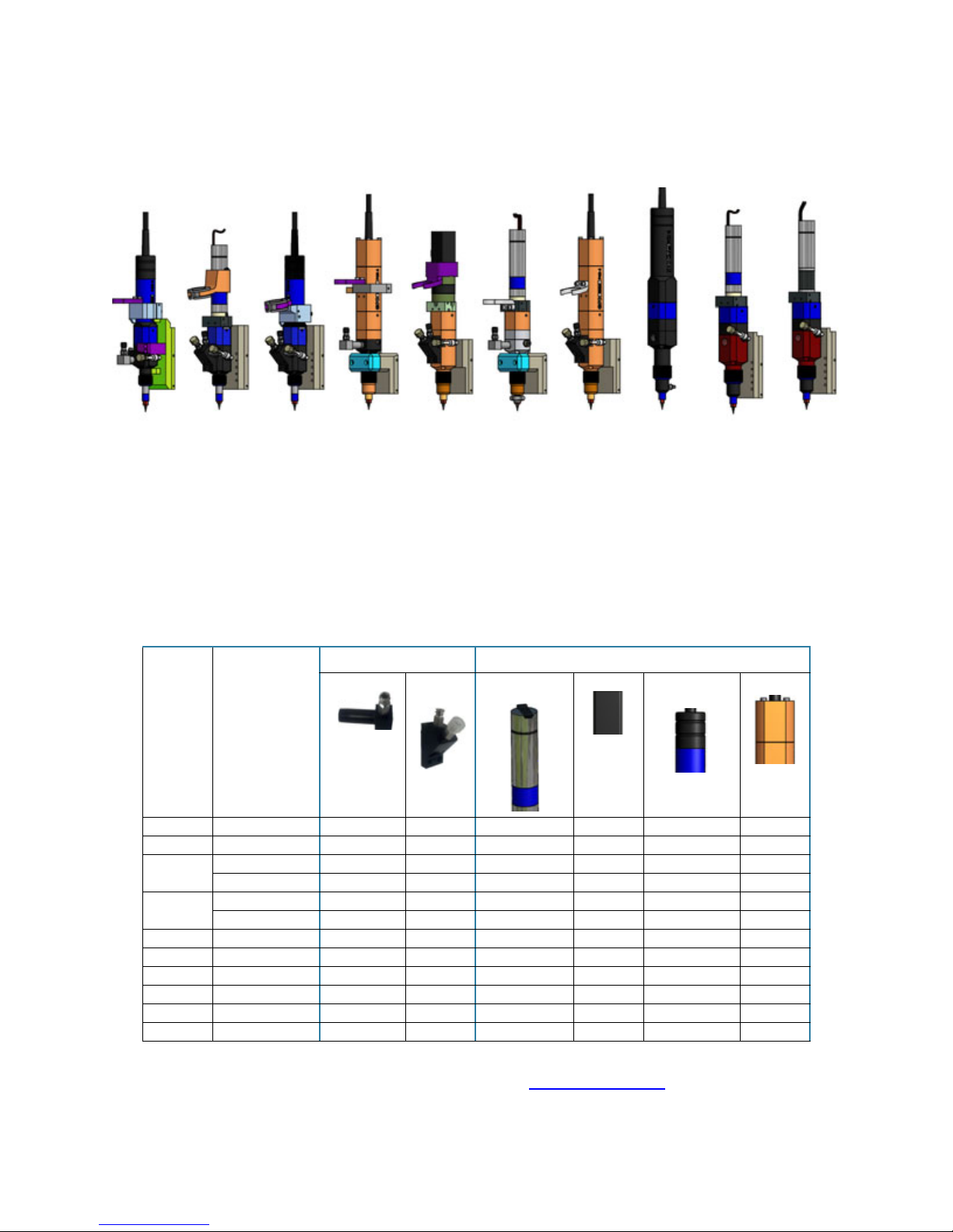
Pump Identification
Figure 1: Models by Name and Part Number
Each pump model can be identified by the type of motor and feed way it uses.
Table 1: Distinguishing Features
Feed Way Motor
High Volume Low
Vol ume
Model Part Number
PCD3 22293093-1004 X X
PCD3L 22293093-1002 X X
PCD3H 22293093-1003 X X
22293121 X X
PCD4 22293081 X X
22293098-0002 X
PCD4L 22293122 X X
PCD4H 22293103 X X
PCD4HB 22293240 X X
PCD6 22293161-001 X X
PCD6HB 22293161-003 X X
PCD7H 22293306-0003 X X
Cylindrical,
Shiny
Square Cylindrical,
Black
Dual Flat
Further individual model detail is available here: Assembly Drawings
2/20/19 GPD Global
®
(pg 34)
2
PCD Pump User Guide Installation
Installation
• Mounting Hardware (pg 3)
• Integration on Robotic Systems
• Integration on Table Top Systems
Mounting Hardware
Any PCD model can be integrated with GPD hardware or non-GPD hardware using either a
GPD Clamp Positioning Mount or a GPD Taper-Lock™.
(pg 4)
(pg 6)
• Taper-Lock™ Mount
• Clamp Positioning Mount
(pg 3)
(pg 3)
Taper-Lock™ Mount
The Taper-Lock™ is a quick, secure, and convenient (no tools required) way to mount any
GPD pump to a system. All PCD pumps use the same Taper-Lock™ hardware.
To mount a PCD pump on non-GPD hardware with a Taper-Lock™ mount:
1. Prepare you hardware to accept the Taper-Lock™hardware. For hole pattern and dimension details, refer to Taper-Lock Mounting Detail - 22110291
(pg 60).
2. Fasten the Taper-Lock™to your hardware.
3. Mount the pump in the Taper-Lock™.
a. Press down and hold the latching lever at the top of the mount.
b. Align and engage the pump with the top dowel pin of the mount.
c. Apply downward pressure to the pump while releasing the latching lever.
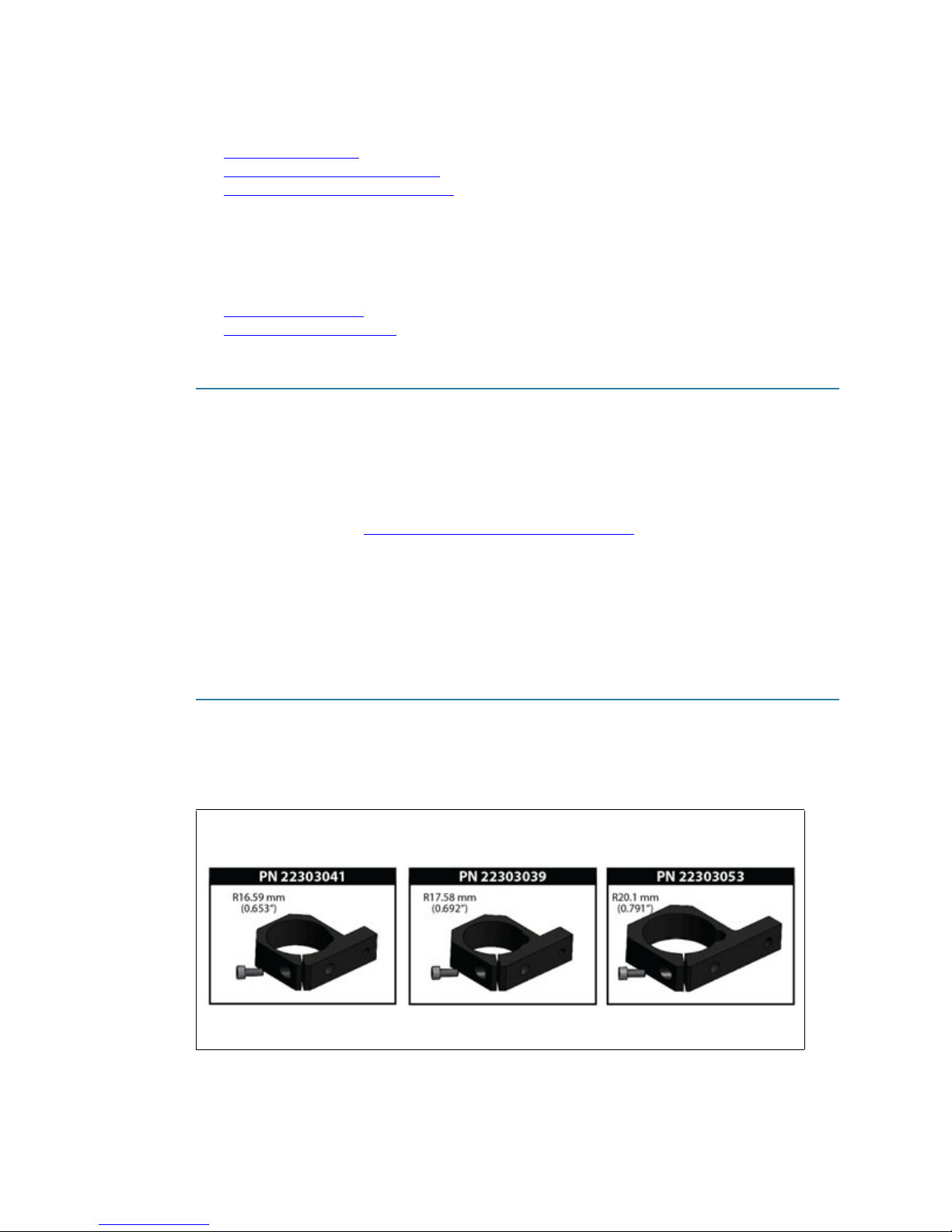
Clamp Positioning Mount
To mount a PCD pump on non-GPD hardware with a Clamp Positioning Mounts:
1. Select a clamp mount sized to fit your PCD pump.
PCD3, PCD3L, PCD3H
2/20/19 GPD Global
Figure 2: Clamp Positioning Mounts by Model*
PCD4, PCD4L, PCD4H,
PCD4HB PCD6, PCD6HB
* All mounts use the same screw: PN SACAM040070010
®
3
PCD Pump User Guide Installation
PCD3 PCD3H PCD3L PCD4H PCD4L
PCD4
PCD6
PCD4HB
PCD6HB
PCD7
PCD7H
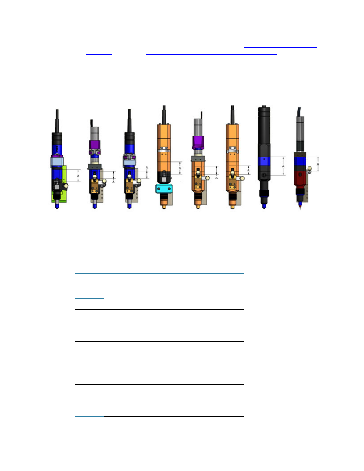
2. Prepare your hardware to accept the clamp mount. Refer to Clamp Mount Dimensions -
22212002 (pg 59) and Clamp Mount Hole Patterns & Groove - 22212002 (pg 58).
3. Fasten the clamp mount to your hardware.
4. Position the PCD pump body so the clamp mount is located within the indicated mounting
range (A), and then tighten the clamp mount screw.
Figure 3: Position Clamp Mount on PCD Body within “A” Range
Integration on Robotic Systems
1
Table 2: Controller Required for Integration by Pump
GPD Integrated
Pump
PCD3
PCD3L
PCD3H
PCD4
PCD4L
PCD4H
PCD4HB
PCD6
PCD6HB
PCD7
PCD7H
Electronic Control System
for MAX Series & DS Series
x
x
x
x
x
Machine Integrated
Controller
x
x
x
x
x
x
2/20/19 GPD Global
®
4

PCD Pump User Guide Installation
Machine Integrated Controller
This GPD Global controller allows integrators to use PCD pumps in their
designs. Requirements:
• 24V signal to enable forward motion
• 24V signal to enable reverse motion
• Variable 0-10V signal to control the speed in forward or reverse
Install on GPD Global MAX Series or DS Series Robotic System
PCD3H, PCD4H, PCD4HB, PCD6HB, PCD7H
To mount one of these PCD pump models on a standard GPD Global MAX Series or DS
Series dispensing system:
1. Mount material on the pump.
2. Mount the pump in the Taper-Lock™ mount:
a. Press down and hold the latching lever at the top of the mount.
b. Align and engage the pump with the top dowel pin of the mount.
c. Apply downward pressure to the pump while releasing the latching lever.
3. Connect the two (2) pump cables into the base of the dispensing system Z-axis motor
cover.
PCD3, PCD3L, PCD4, PCD4L, PCD6, PCD7H
NOTE: To operate pump models PCD3, PCD3L, PCD4, and PCD4L, the GPD Global MAX
Series or DS Series dispensing system must be configured with a tabletop controller and cable
for pump control. To mount one of these PCD pump models on an upgraded dispensing
system (configured with a tabletop controller and cable):
1. Mount material on the pump.
2. Press the dispenser MOTION STOP button to remove power from the PCD controller.
3. Mount the pump in the Taper-Lock™ mount:
a. Press down and hold the latching lever at the top of the mount.
b. Align and engage the pump with the top dowel pin of the mount.
c. Apply downward pressure to the pump while releasing the latching lever.
4. Connect the pump cable to the dispenser receptacle panel.
5. Release the MOTION STOP button to return power to the PCD controller.
Install on Non-GPD Equipment
For easy-installation options available for mounting any model of PCD pump on non-GPD
hardware, refer to Mounting Hardware
(pg 3).
2/20/19 GPD Global
®
5
PCD Pump User Guide Installation
Integration on Table Top Systems
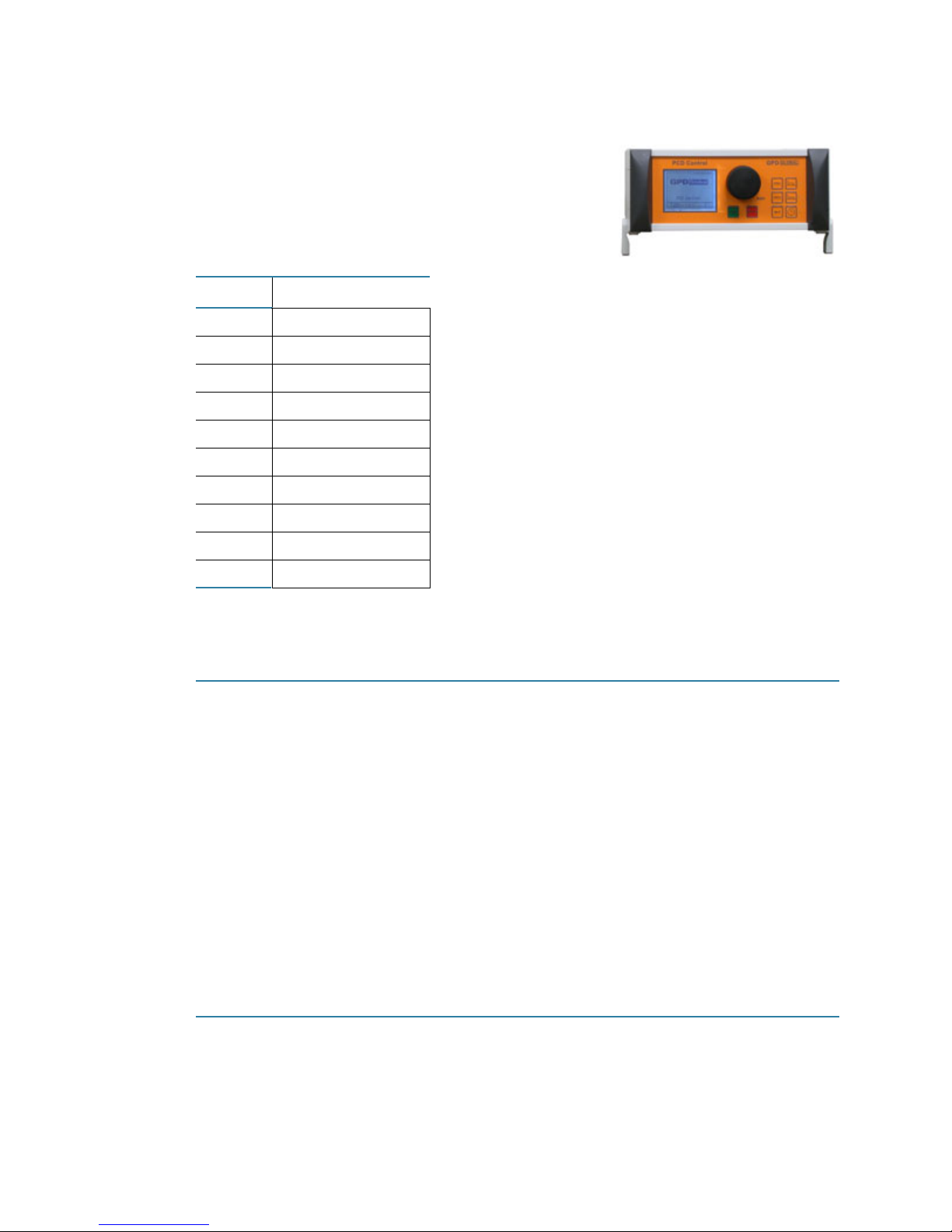
All relevant settings for your production results can be
easily saved via a graphic user interface if you operate
your dispense pump with a GPD Global PCD Tabletop
Controller especially matched to the pump.
Table 3: Pumps with Table Top
Capability
Pump Controller
PCD3
PCD3L
PCD3H
PCD4
PCD4L
PCD4H
PCD4HB
PCD6
PCD6HB
PCD7H
x
x
–
x
x
–
–
x
–
x
Install on GPD Global Island Series Robotic System
PCD3, PCD3L, PCD4, PCD4L, PCD6, PCD7H
To mount a PCD pump on a GPD Global Island Series dispensing system:
1. Turn off the PCD Tabletop Controller or, if system is configured with one, turn off the pump
power switch.
2. Mount the pump in the Taper-Lock™mount:
a. Press down and hold the latching lever at the top of the mount.
b. Align and engage the pump with the top dowel pin of the mount.
c. Apply downward pressure to the pump while releasing the latching lever.
3. Connect the pump cable to the power port on the Z axis.
4. Turn on the PCD Tabletop Controller or, if your system is configured with one, turn on the
pump power switch.
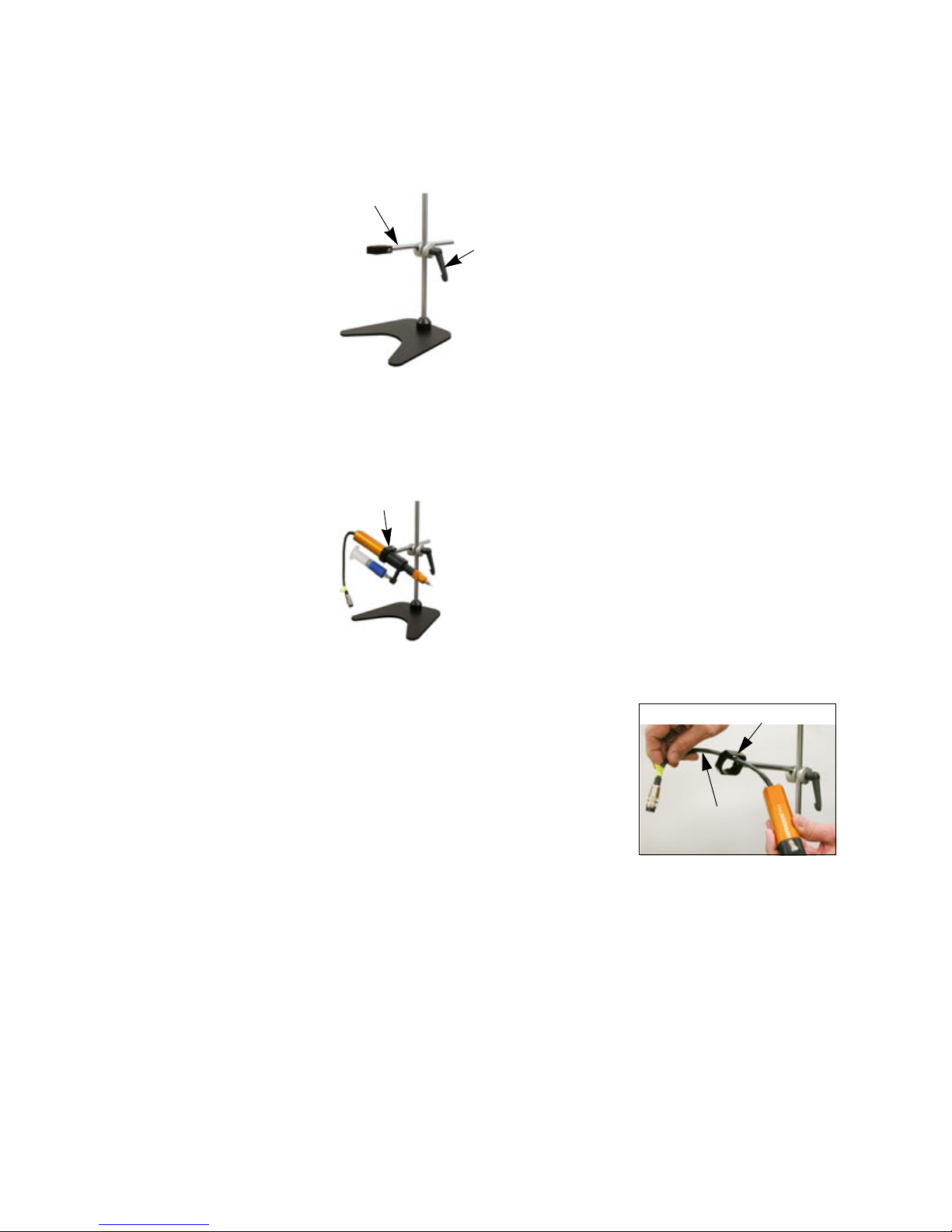
Install Pump in PCD Table Stand
PCD3, PCD3L, PCD4, PCD4L, PCD6, PCD7H
To mount a PCD pump in a PCD Table Stand:
1. Place a PCD Table Stand on a level surface.
2/20/19 GPD Global
®
6
PCD Pump User Guide Installation
(A) Extension arm
(B) Clamp handle
(C) Bracket screw
(D) Cable
(E) Bracket
2. Prepare the PCD Table Stand to hold a pump:
a. With one hand, support the extension arm (Item A) while loosening the clamp handle
(Item B) with the other hand.
b. As needed, slide and rotate the extension arm vertically and laterally to establish
desired position and orientation.
c. To lock the extension arm in place, tighten the clamp handle.
d. Using a 4 mm Allen key, loosen the bracket screw (Item C).
3. Mount a pump in the PCD Table Stand:
a. Disconnect the pump cable from the pump controller.
b. Feed the pump cable (Item D) through the bracket
(Item E).
c. Then position the pump in the bracket so the central
barrel (black section) of the pump is positioned in the
bracket as shown above.
d. Tighten the bracket screw (Item C).
2/20/19 GPD Global
®
7
PCD Pump User Guide Operations
Operations
Prior to operations, identify which model of PCD pump you will be using. Each PCD pump
model can be identified by the type of motor and feed way it uses; see details under Pump
Identification (pg 2).
1- Read Safety Notices
IMPORTANT: Prior to start up, read Safety Notices (pg iii) as this information must be read
and understood prior to using the pump!
2- Initial Start Up
CAUTION: Do not switch on the dispense pump before medium has been fed into it. There is a
danger of damage to the pump if it is run dry. Even a brief period of dry run time can lead to the
destruction of the stator.
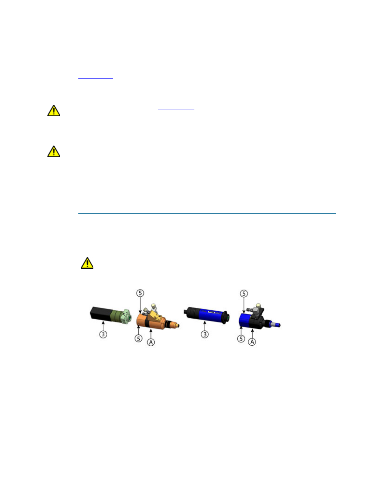
A- Disconnect Dispense Unit from Drive Unit
PCD3, PCD3L, PCD3H, PCD4, PCD4L, PCD4H, PCD4HB, PCD6, PCD6HB,
PCD7H
To disconnect the dispense and drive units from each other:
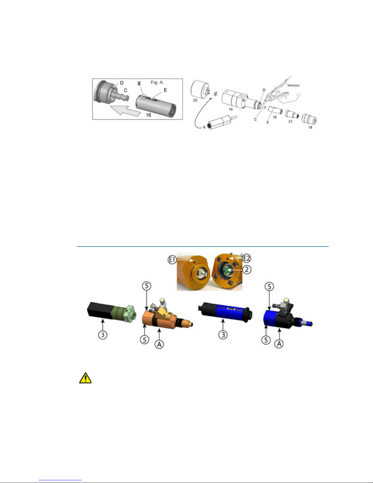
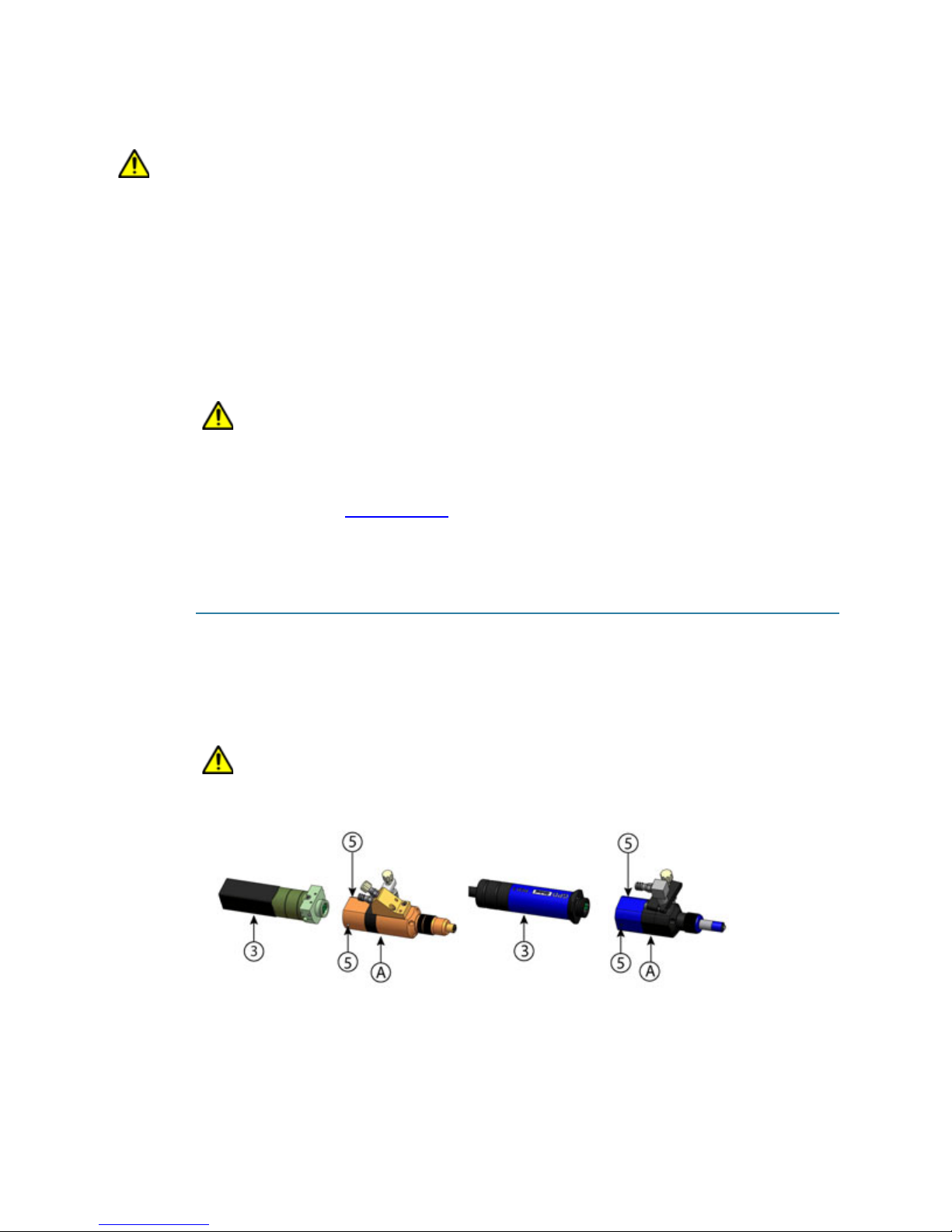
1. Loosen the two (2) set screws (Item 5).
2. Gently pull the drive unit (Item 3) away from the dispense unit (Item A).
CAUTION: Proceed carefully to avoid damage to the fit.
2/20/19 GPD Global
®
8
PCD Pump User Guide Operations
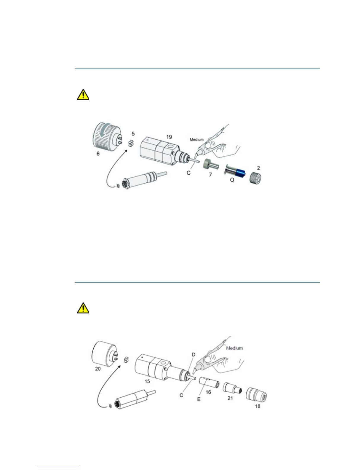
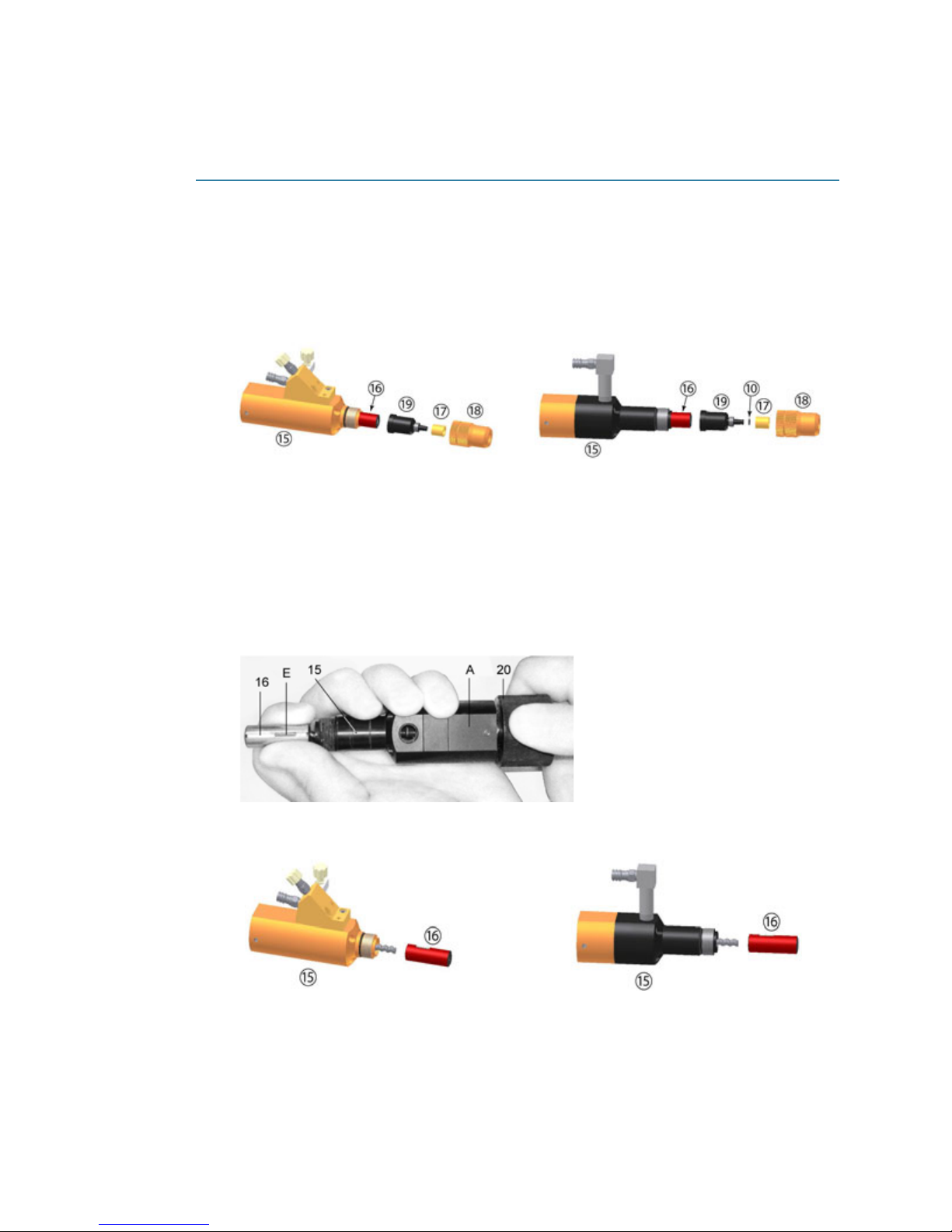
B- Insert Stator
PCD3, PCD3L, PCD3H
To attach the stator for the first time:
CAUTION: DO NOT assemble the pump dry. There is a danger of damage to the pump if it is
run dry. Even a brief period of dry run time can lead to the destruction of the stator.
1. Unscrew the union ring (Item 2) from the dispenser housing (19).
2. Remove the stator cover (Item Q) and set aside.
3. Wet the rotor (Item C) with the medium to be used or a suitable lubricant.
4. Screw the stator (Item 7) onto the rotor (Item C) until it reaches the limit on the body (Item
19). There will be approximately 1 mm between the end of the stator and the threads of
the dispenser housing.
5. Place the stator cover (Item Q) over the stator (Item 7) and install the union ring (Item 2),
firmly clamping the two pieces together.
PCD4, PCD4L, PCD4H, PCD4HB, PCD6, PCD6HB, PCD7H
To insert the stator for the first time:
CAUTION: DO NOT assemble the pump dry. There is a danger of damage to the pump if it is
run dry. Even a brief period of dry run time can lead to the destruction of the stator.
1. Unscrew the union ring (Item 18), and then slide both the union ring and threaded sleeve
(Item 21) away from dispenser housing (Item 15).
2/20/19 GPD Global
®
9
PCD Pump User Guide Operations
2. Couple the assembly aid (Item 20) to the dispense pump housing (Item 15). The starshaped coupling (Item 5) must be attached to the dispenser pump housing (Item 15).
3. Wet the rotor (Fig A, Item C) with the medium or a suitable lubricant.
4. Orient the ‘X’ end (see Fig. A) of the stator (Item 16) toward the rotor (Item C) and then
turn the stator on the rotor until the dowel pin begins to engage with the key way (Fig. A,
Item D).
5. Lightly press the stator in the direction of the dispenser housing (Item 15) and turn the
assembly aid in the direction of the arrow until the stator has been guided into the dispense pump housing. The dowel pin will barely be visible in the key way (Item D).
6. Uncouple the assembly aid, install the end piece and the union ring, and attach the
required needle/nozzle.
C- Connect Dispense Unit to Drive Unit
PCD3, PCD3L, PCD3H, PCD4, PCD4L, PCD4H PCD4HB, PCD6, PCD6HB,
PCD7H,
To connect the dispense and drive units together:
CAUTION: Proceed carefully to avoid damage to the fit.
1. Loosen the two (2) set screws (Item 5) so they do not protrude into the coupling area.
2. Verify the star coupling (Item 2) is seated properly in the dispense unit (Item A).
NOTE: Inspect the star-shaped coupling (Item 2) and adjacent O-ring for wear. Replace
these items as needed
2/20/19 GPD Global
®
10
PCD Pump User Guide Operations
PCD4, PCD4HB PCD4L, PCD4HPCD3
32
32
32
31
31
F
PCD3L, PCD3H PCD6, PCD6HB
32
F
31
PCD7, PCD7H
3. Couple the drive unit (Item 3) with the dispense unit (Item A) until there is a gap <1 mm
between the anti-rotation lock (Item E1) and the dispense unit (Item A).
4. Rotate the drive unit (Item 3) until the anti-rotation lock (E1) aligns with the anti-rotation
lock feature (Item E2) of the dispense unit (Item A).
5. Press the drive unit (Item 3) and the dispense unit (Item A) together completely.
6. Lightly turn the set screws (Item 5) to secure units together.
3- Prime Pump with Medium
CAUTION: Follow the safety stipulations and instructions of the manufacturer of the medium to
be used to fill the unit. If applicable, use protective equipment.
NOTE: Priming a pump can be performed online or offline. When working offline, GPD Global
recommends using the Install Pump in PCD Table Stand
PCD3, PCD3L, PCD3H, PCD4, PCD4L, PCD4H, PCD4HB, PCD6, PCD6HB,
PCD7H
1. Connect a material reservoir (cartridge, supply line, tank) of material to the pump adapter/
feed reservoir (Item 32). For thread details, refer to Threads & Materials
(pg 6) method.
(pg 31).
2. Connect air (0.14-0.2 bar [2-3 psi]) to the material reservoir.
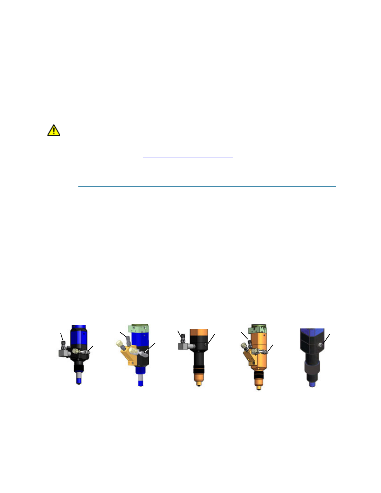
3. For applicable models, verify the purge tube support (Item 31) is secured in the tube support and then remove the cap. For all other models, remove the bleed port plug (Item F).
4. Orient the dispense pump so the needle/nozzle end points downward.
5. Increase air pressure on the material reservoir until material feeds into the purge tube (or
out of the bleed port. Using a cup or wipe to catch expelled material, allow a small amount
of material to bleed from the purge tube to ensure all air is displaced.
6. For applicable models, screw the cap onto the purge tube. For all other models, screw the
bleed port plug (Item F) into the bleed port.
Figure 4: Adapter/feed reservoir (32), purge tube support (31), & bleed port plug (F) by pump model
4- Install Pump
2/20/19 GPD Global
Refer to Installation (pg 3).
®
11

PCD Pump User Guide Maintenance
Maintenance
Cleaning Time
Cleaning a pump requires 15 minutes or more. The amount of time required relates
directly to type of material and solvent used.
Cleaning Kit
PCD Pump Series Cleaning Kit (PN 22110467)
Kit contents are illustrated in this document: KITS: Spare Parts/Setup/Cleaning (PN
22290036).
Cleaning Frequency Guidelines
Initially, a once a month inspection and cleaning is recommended, then based on your
experience using with the pump and fluid, extend or shorten the cleaning interval as
needed.
Cleaning frequency is determined according to the type of fluid being dispensed. For
pumps in continuous use, clean in intervals no greater than 3 x fluid pot life. For
pumps dispensing fluids stable at room temperature and that have no significant pot
life issues, the pump may be run continually without issue.
Cleaning Procedures
• Flush Pump
• Clean PCD3, PCD3L, PCD3H
• Clean PCD4, PCD4L, PCD4H, PCD4HB, PCD6, PCD6HB, PCD7H
(pg 12)
(pg 13)
(pg 17)
Flush Pump
The flush procedure is used primarily when underfill material needs to be purged from the
pump. The dispense tip and needle can be removed or left in place:
• The dispense tip may be left in place or removed during the flush procedure.
• If a disposable needle is present, remove and discard it.
• A needle intended for reuse can remain in place on the pump as the flush procedure will
clean the needle.
To flush fluid from the pump:
1. Remove the fluid reservoir from the pump.
2. If present, remove disposable needle.
3. Install an empty syringe on the pump.
4. Fill the syringe with a suitable solvent.
5. Set the pump to purge into a purge cup or suitable container.
6. Continue to purge until all dispense fluid has been purged and only solvent is exiting the
pump.
2/20/19 GPD Global
®
12
PCD Pump User Guide Maintenance
Clean PCD3, PCD3L, PCD3H
IMPORTANT: Wear suitable protective clothing if chemical, corrosive, or dangerous products
are to be used. Note and comply with the safety stipulations and the information from the manufacturer. Ensure sufficient bleeding or extraction of air. Take special safety precautions if working
with dangerous media; for example, provide eye flushing facilities if working with corrosive
chemicals.
1 - Cleaning Kit
Obtain the recommended Cleaning Kit (pg 12).
2- Flush Pump
Prior to disconnecting the pump from its power source, flush the pump with a syringe of appropriate solvent, stopping the flush before pump runs dry.
CAUTION: Never run the pump dry. There is a danger of damage to the pump if it is run dry.
Even a brief period of dry run time can lead to the destruction of the stator.
3- Remove Power
Disconnect the drive unit power supply and uncouple it from the dispensing unit in the reverse
order as described in 4- Install Pump
(pg 11).
4- Remove Drive Unit from Dispense Unit
PCD3, PCD3L, PCD3H
1. Remove material syringe (not shown) and set it aside.
2. Remove the needle/nozzle (not shown) and either clean or dispose of it.
3. Partially loosen set screws (Item 5).
4. To separate drive unit (Item 3) from dispense unit (Item A), pull units apart.
CAUTION: Proceed carefully to avoid damage to the fit.
2/20/19 GPD Global
®
13

PCD Pump User Guide Maintenance
5- Remove & Clean Stator
PCD3, PCD3L, PCD3H
To access the stator (Item 7):
1. Unscrew and remove union ring (Item 2).
2. Remove the stator assembly (Item 3) by unscrewing it (do NOT pull) from the dispenser
housing (Item 19).
3. Remove the stator cover (Item Q) from the stator (Item 7) and, as needed, clean stator
cover.
4. Carefully and thoroughly clean stator (Item 7) using swabs and brushes supplied in the
cleaning kit. Remove all debris; anything less than a thorough cleaning can affect pump
performance.
RECOMMENDATION: To clean the stator thoroughly, use an ultrasonic cleaner with an
appropriate solvent.
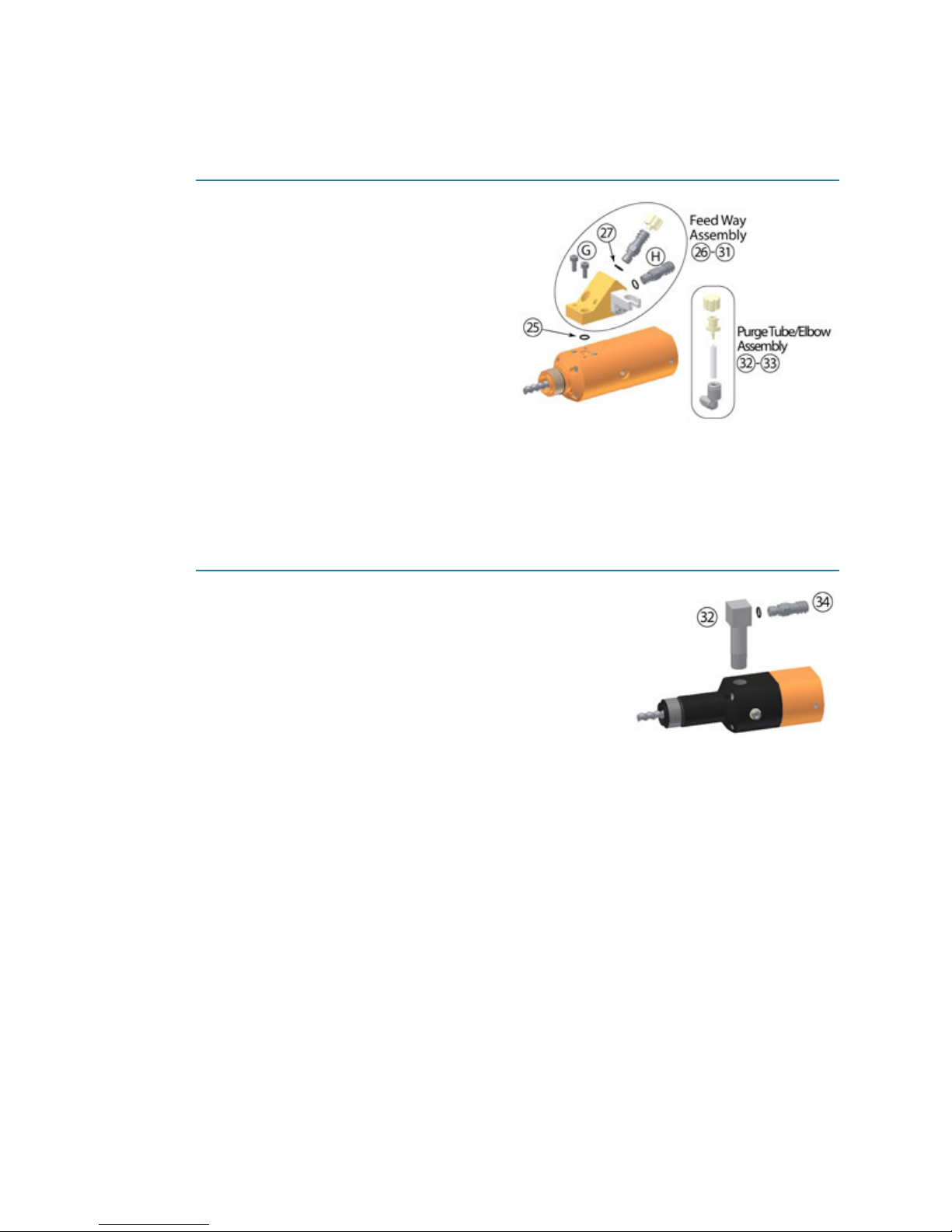
6- Remove & Clean Feed Way
PCD3L, PCD3H
1. To separate the feed way assembly (Items 26-31) and O-ring (Item 25) from the pump
body, remove screws (Item G).
2. Clean feed way assembly (Items 26-31):
a. Remove luer feed ways (Item H) and associated O-rings. Replace O-rings if brittle or
worn.
b. Clean and flush feed way body and luer feed ways (H) using cleaning kit supplies.
c. Inspect and clean O-ring (Item 25). Replace O-rings if brittle or worn.
2/20/19 GPD Global
®
14
PCD Pump User Guide Maintenance
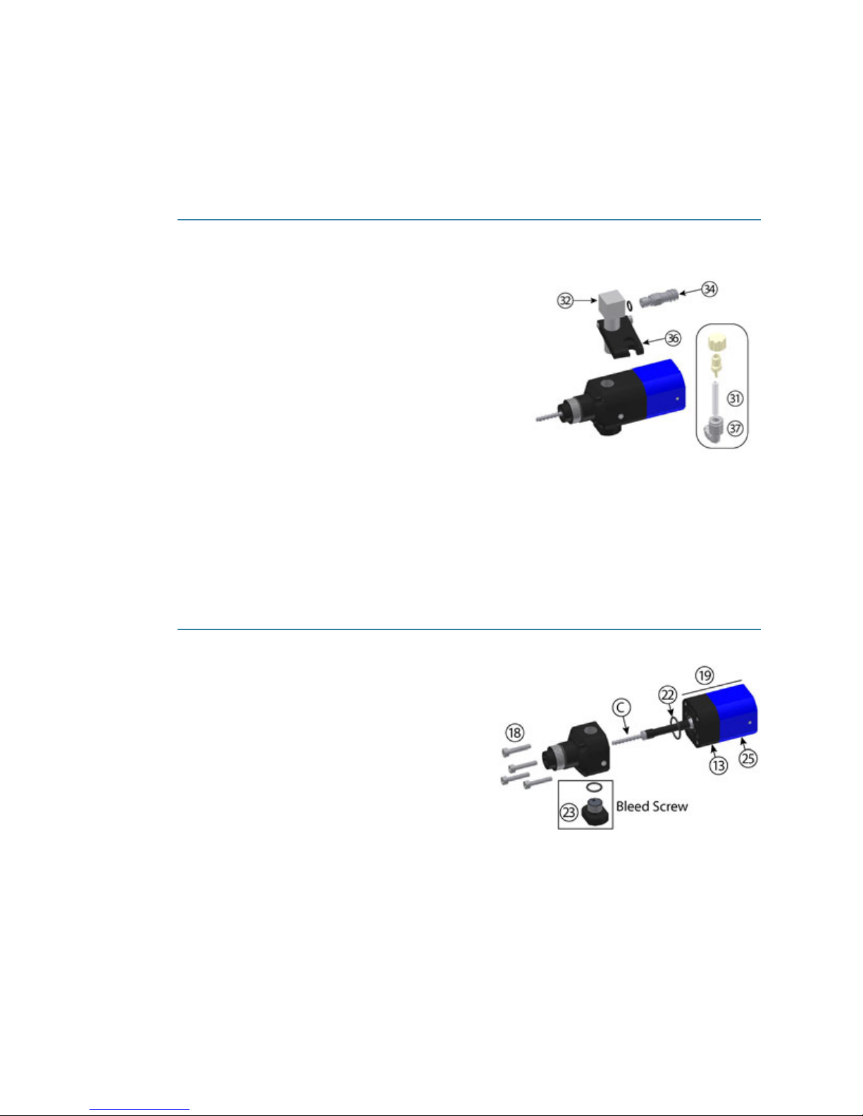
3. Unscrew and remove the purge tube/elbow assembly (Items 32-33) by pressing inward
slightly while compressing the ring on elbow.
4. Replace the purge tube and clean the elbow. The elbow will need to be replaced after being
cleaned several times; use good judgement regarding cleanliness of elbow.
PCD3
1. Separate the purge tube (Item 31) from the purge tube support (Item 36).
2. Unscrew the feed way (Items 32) from the pump
body.
3. Separate the luer feed way (Item 34) and associated O-ring from the feed way (Item 32).
4. Clean and flush feed way and luer feed way using
cleaning kit supplies.
5. Inspect and clean O-ring. Replace O-ring if brittle
or worn.
6. Remove and clean the purge tube assembly:
a. Remove the purge tube (Item 31) from the
elbow (Item 37) by pulling down on the orange
ring and then pulling the purge tube out of the elbow.
b. Using a crescent wrench, unscrew the elbow (Item 37) from the pump body.
c. Replace the purge tube and clean the elbow. The elbow will need to be replaced after
being cleaned several times; use good judgement regarding cleanliness of elbow.
7- Clean Dispenser Housing & Rotor
PCD3, PCD3L, PCD3H
1. If a bleed screw (Item 23) is present, remove
it from dispenser (Item 19) and verify the
rubber disk that fits into the bleed screw has
been removed from dispenser housing; otherwise, skip this step.
2. Remove screws (Item 18) and then separate
dispenser housing (Item 19) from “bearing
housing with rotor” assembly (Items 13 and
25).
3. Inspect and clean O-ring (Item 22). Replace
if it is brittle or worn.
4. Using a cloth and brush, clean thoroughly:
– dispenser housing (Item 19)
– rotor (see Item C)
– (if present) bleed screw (Item 23) and rubber disk
CAUTION: DO NOT rinse “bearing housing with rotor” (Items 13 and 25) or submerge it in
an ultrasonic cleaner as either action could damage bearings.
2/20/19 GPD Global
®
15

PCD Pump User Guide Maintenance
8- Clean Seal Housing
IMPORTANT: Perform this step only
as needed; in rare cases, the seal
housing (Item 25) may need to be
cleaned.
1. Remove screws (Item 26).
2. Unsnap and pull seal housing
(Item 13) over rotor (Item C) and away from bearing housing (Item 25).
3. Thoroughly clean seal housing (Item 13).
4. Inspect and clean the two O-rings (Item 16). Replace if brittle or worn.
5. Liberally lubricate the seal housing (Item 13) using lubricant listed on Parts Lists
9- Reassemble Pump
To reassemble the pump:
1. Perform 8- Clean Seal Housing
2. Do not exceed a tightening torque of 0.35 Nm while performing 7- Clean Dispenser Hous-
ing & Rotor (pg 15) in reverse order.
3. Perform 6- Remove & Clean Feed Way
4. Install the stator according to B- Insert Stator
5. Connect the dispensing unit to the drive unit per C- Connect Dispense Unit to Drive Unit
(pg 10).
(pg 23).
(pg 16) in reverse order.
(pg 14) in reverse order.
(pg 9)
2/20/19 GPD Global
®
16

PCD Pump User Guide Maintenance
Clean PCD4, PCD4L, PCD4H, PCD4HB, PCD6, PCD6HB, PCD7H
IMPORTANT: Wear suitable protective clothing if chemical, corrosive, or dangerous products
are to be used. Note and comply with the safety stipulations and the information from the
manufacturer. Ensure sufficient bleeding or extraction of air. Take special safety precautions if
working with dangerous media; for example, provide eye flushing facilities if working with
corrosive chemicals.
1 - Cleaning Kit
Obtain the recommended Cleaning Kit (pg 12).
2- Flush Pump
Prior to disconnecting the pump from its power source, flush the pump with a syringe of appropriate solvent, stopping the flush before pump runs dry.
CAUTION: Never run the pump dry. There is a danger of damage to the pump if it is run dry.
Even a brief period of dry run time can lead to the destruction of the stator.
3- Remove Power
Disconnect the drive unit power supply and uncouple it from the dispensing unit in the reverse
order as described in 4- Install Pump
(pg 11).
4- Remove Drive Unit from Dispense Unit
PCD4, PCD4L, PCD4H, PCD4HB, PCD6, PCD6HB
1. Remove material syringe (not shown) and set it aside.
2. Remove the needle/nozzle (not shown) and either clean or dispose of it.
3. Partially loosen set screws (Item 5).
4. To separate drive unit (Item 3) from dispense unit (Item A), pull units apart.
CAUTION: Proceed carefully to avoid damage to the fit.
2/20/19 GPD Global
®
17
PCD Pump User Guide Maintenance
5- Remove & Clean Stator
PCD4, PCD4L, PCD4H, PCD4HB, PCD6, PCD6HB, PCD7H
1. To access the stator (Item 16):
a. Unscrew and remove union ring (Item18) and end piece assembly (Items 17 and 19)
from dispenser housing (Item 15).
b. Unscrew threaded sleeve (Item 17) from end section (Item 19) and, as needed, clean
threaded sleeve.
c. If an O-ring (Item 10) is present, inspect and clean the O-ring. Replace if it is brittle or
worn.
2. To unscrew the stator (Item 16) from the dispenser housing (Item 15) without separating
the pin (Item E) mounted on the stator:
a. Hold dispenser housing (Item 15) in the palm of one hand with the stator (Item 16)
loosely secured between thumb and forefinger of the same hand.
b. With the other hand, couple and turn the assembly aid (Item 20) counterclockwise in
the base of the dispense unit (Item A) until the stator completely separates from the
dispenser housing (Item 15).
c. Uncouple the assembly aid (Item 20) from the dispenser unit (Item A).
3. Carefully pull the stator (Item 16) away from dispenser housing (Item 15).
4. Carefully and thoroughly clean the stator (Item 16) using swabs supplied in the cleaning
kit. Remove all debris; anything less than a thorough cleaning can affect pump performance.
RECOMMENDATION: To clean the stator thoroughly, use an ultrasonic cleaner with an
appropriate solvent.
2/20/19 GPD Global
®
18
PCD Pump User Guide Maintenance
6- Remove & Clean Feed Way
PCD4L, PCD4H, PCD4HB
1. To separate the feed way assembly
(Items 26-31) and O-ring (Item 25) from
the pump body, remove screws (Item G).
2. Clean feed way assembly:
a. Remove luer feed ways (Item H) and
O-rings (Item 27). Replace O-rings if
brittle or worn.
b. Clean and flush feed way body and
luer feed ways (Item H) using cleaning kit supplies.
c. Inspect and clean O-ring (Item 25).
Replace O-rings if brittle or worn.
3. Unscrew and remove the purge tube/elbow assembly (Items 32-33) by pressing inward
slightly while compressing the ring on elbow.
4. Replace the purge tube and clean the elbow. The elbow will need to be replaced after being
cleaned several times; use good judgement regarding cleanliness of elbow.
PCD4, PCD6, PCD6HB, PCD7H
1. If present, unscrew the feed way (Items 32) from the
pump body.
2. Separate the luer feed way (Item 34) and O-ring from the
feed way (Item 32).
3. Clean and flush feed way and luer feed way using cleaning kit supplies.
4. Inspect and clean O-ring. Replace O-ring if brittle or
worn.
2/20/19 GPD Global
®
19
PCD Pump User Guide Maintenance
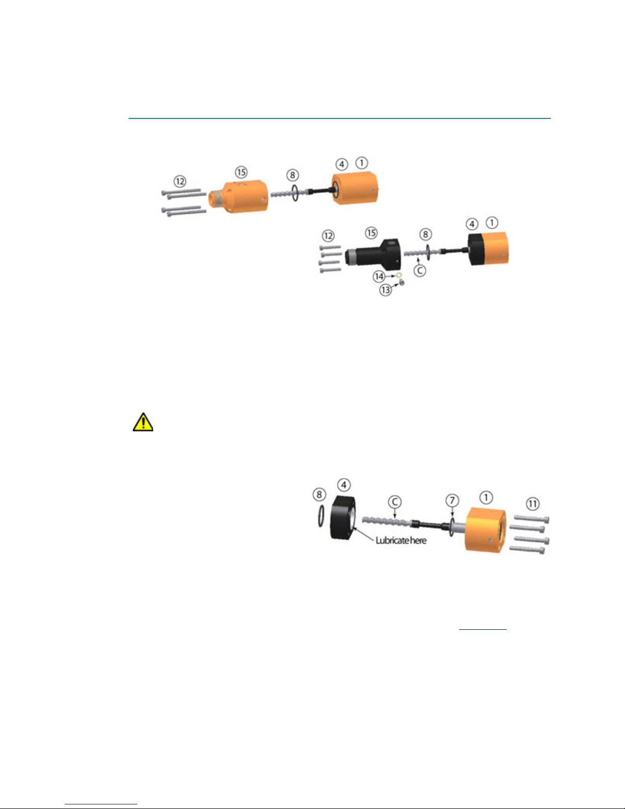
7- Clean Dispenser Housing & Rotor
PCD4, PCD4L, PCD4H, PCD4HB, PCD6, PCD6HB, PCD7H
1. If a bleed screw (Item 13) and washer (Item 14) are present, remove them from the dispenser housing (Item 15); otherwise, skip this step.
2. Remove screws (Item 12) and then separate dispenser housing (Item 15) from “bearing housing with rotor” assembly (Items 1 and 4).
3. Inspect and clean O-ring (Item 8). Replace if it is brittle or worn.
4. Using a cloth and brush, clean thoroughly:
– dispenser housing (Item 15)
– rotor (Item C)
– (if present) bleed screw (Item 13) and washer (Item 14)
CAUTION: DO NOT rinse “bearing housing with rotor” (Items 1 and 4) or submerge it in an
ultrasonic cleaner as either action could damage bearings.
8- Clean Seal Housing
IMPORTANT: Perform this step only
as needed; in rare cases, the seal
housing (Item 4) may need to be
cleaned.
1. Remove screws (Item 11).
2. Unsnap and pull seal housing
(Item 4) over rotor (Item C) and away from bearing housing (Item 1).
3. Thoroughly clean seal housing (Item 4).
4. Inspect and clean the O-rings (Items 7 & 8). Replace if brittle or worn.
5. Liberally lubricate the seal housing (Item 13) using lubricant listed on Parts Lists
(pg 23).
2/20/19 GPD Global
®
20

PCD Pump User Guide Maintenance
9- Reassemble Pump
To reassemble the pump:
1. Perform 8- Clean Seal Housing
(pg 20) in reverse order.
2. Do not exceed tightening torque specified below while performing 7- Clean Dispenser
Housing & Rotor (pg 20) in reverse order.
Pump Model Maximum Tightening Torque
PCD4
PCD4L
PCD4H
PCD6
PCD7
3. Perform 6- Remove & Clean Feed Way
4. Install the stator according to B- Insert Stator
0.35 Nm
0.5 Nm
(pg 14) in reverse order.
(pg 9)
5. Connect the dispensing unit to the drive unit per C- Connect Dispense Unit to Drive Unit
(pg 10).
2/20/19 GPD Global
®
21

PCD Pump User Guide Troubleshooting
Troubleshooting
Table 4: Troubleshooting
Error Possible Cause Correction
No or too little medium
conveyed
Dripping / “running on” of
the medium
Dispense results include
bubbles or skips. Example: Figure 5
Needle blocked. Clean/replace the needle.
Medium hardened. Dispenser clean.
Needle too small or too long. Use a different needle cross-section. Reduce the
speed / flow rate.
Stator swollen. Replace the stator.
Inadequate supply of medium. Supply the medium, check the hose, check the
primary pressure and increase it if necessary.
Motor not connected. Connect the motor.
Sucking back not set correctly. Set the sucking back.
Air bubbles in the medium. Bleed the medium.
Medium compressible. Degas the medium.
The Union ring may have been tightened too much. The union ring holds
the stator in place during dispensing.
If the union ring is too tight, it can collapse the stator on the rotor and
cause voids in dispensed material.
Figure 5: Dispense results include bubbles or skips.
1 - Loosen the union ring 1/8 turn to 1/4 turn.
2 - Rerun dispense process and inspect results.
3 - Repeat above steps until desired results are
attained. Example: Figure 6
2/20/19 GPD Global
Figure 6: Desired results - no bubbles or skips.
®
22

PCD Pump User Guide Parts Lists
Parts Lists
For consumable, spare, and general part information, refer to this document:
PCD Pump Parts List (PN 22200613).
Specifications
• PCD3 Specifications (pg 24)
• PCD4 Specifications
• PCD6 Specifications
• PCD7 Specifications
• Additional Dimensions
• Threads & Materials
(pg 25)
(pg 26)
(pg 27)
(pg 28)
(pg 31)
2/20/19 GPD Global
®
23

GPD Global
©
Specifications
2/20/19 PCD Pump User Guide 24
Tabl e 5 : PCD3 Specifications
Specification
PCD3
22293093-1004
PCD3L
22293093-1002
PCD3H
22293093-1003, 22293121
Dimensions (height, SQ, diameter)
Also see
Additional Dimensions (pg 28)
207.56, SQ 29x29, ø 34.80 mm
(8.176”, SQ 1.142”x1.142”, ø 1.3”)
208.28, SQ 29x29, ø 34.80 mm
(8.176”, SQ 1.142”x1.142”,
ø
1.3”)
220.73, SQ 29x29, ø 34.80 mm
(8.176”, SQ 1.142”x1.142”, ø 1.3”)
Weight approx. 380 g (0.8 lb) approx. 556 g (1.2 lb) approx. 451 g (1.0 lb)
Dispensing volume
≈ 0.012 ml/rotation
Theoretical flow rate per minute ** 0.12 to 1.48 ml/min
Minimum dispensing amount ml 0.001 ml 0.0005 ml
Priming volume
≈ 3 cc ≈1.5 cc
Dispensing precision * ±1%
Repeat accuracy >99%
Minimum operating pressure 0 bar (0 psi), with self-leveling liquid
Maximum operating pressure 0-6 bar (0-87 psi), with non-self-leveling liquid
Maximum dispensing pressure *** 16-20 bar (232-290 psi)
Self-sealing * approx. 2 bar (29 psi)
Maximum viscosity‡ 60,000 cps
Parts touched by medium HD-POM, Stainless steel, Anodized Aluminum
Sealings High-molecular PE, VisChem
Sealings static O-ring Viton
Motor 18 - 24 VDC 24 VDC
Motor rotating speed, per minute 0-120 rpm
Operating ambient conditions
° C
+10 to +40 non-condensing, air pressure 1 bar (14.5 psi)
Medium temperature
° C
+10 to +40
Storage conditions/temp.
° C
dry and dust free, -10 to +40
Cable dimensions O.D.: 9.423 mm (0.371”). Length: 250 mm (10”), extension cable available
Cable flexibility
High flex cable; flex cycles 5 million minimum. Bending radius -min: 5 x d, opt: 10 x d
Cable features
Max voltage 600V. Copper 22AWG. 6 cores of TPE-E. Black jacket of FHF, PUR. Connector at each end.
* Reference medium approx. 1.000 mPas at 20 ° C. Maximum dispensing pressure and self-sealing
decrease with decreasing viscosity and increase with increasing viscosity.
** Volume flow dependent on viscosity and primary pressure.
*** Maximum dispensing pressure and self-sealing decrease with decreasing viscosity and increase with increasing viscosity.
‡Higher viscosity may be possible based on nozzle size and flow rate.

GPD Global
©
Specifications
2/20/19 PCD Pump User Guide 25
Table 6: PCD4 Specifications
Specification
PCD4
22293081
22293098-0002
PCD4L
22293122
PCD4H
22293103
PCD4HB
22293240
Dimensions (height, SQ, dia.)
Also see Additional Dimensions
(pg 28)
230.28, SQ 29, ø 35 mm
(9.457”, SQ 1.142”, ø 1.378”)
230.35, SQ 29, ø 35 mm
(9.457”, SQ 1.142”, ø 1.378”)
240.2, SQ 29, ø 35 mm
(9.457”, SQ 1.142”, ø 1.378”)
252.1, SQ 29, ø 35 mm
(9.927”, SQ 1.142”, ø 1.378”)
Weight approx. 420 g (0.9 lb) 671 g (1.48 lb) approx. 689 g (1.52 lb)
Dispensing volume ≈0.05 ml/rotation
Theoretical flow rate per minute *** 0.5-6.0 ml/min 0.2-6.0 ml/min
Minimum dispensing amount ml * 0.004 ml 0.001 ml
Priming volume ≈ 3 cc ≈ 1.5 cc
Precision ml ±, absolute * ±1%
Repeat accuracy >99%
Minimum operating pressure 0 bar (0 psi), with self-leveling liquid
Maximum operating pressure 0-6 bar (0-87 psi)
Maximum dispensing pressure 16-20 bar (232-290psi)
Self-sealing ** approx. 2 bar (29 psi)
Maximum viscosity‡ 60,000 cps
Parts touched by medium HD-POM, Stainless Steel, Anodized Aluminum
Sealings High-molecular PE, VisChem
Sealings static O-ring Viton
Motor 18-24 VDC incremental encoder Servo
Motor rotating speed, per minute 0-120 rpm
Operating ambient conditions
° C
+10 to +40 non-condensing, air pressure 1 bar (14.5 psi)
Medium temperature
° C
+10 to +40
Storage conditions/temp.
° C
dry and dust free, -10 to +40
Cable dimensions O.D.: 9.423 mm (0.371”). Length: 250 mm (10”), extension cable available
Cable flexibility High flex cable; flex cycles 5 million minimum. Bending radius -min: 5 x d, opt: 10 x d
Cable features
Max voltage 600V. Copper 22AWG. 6 cores of TPE-E. Black jacket of FHF, PUR. Connector at each end.
* Reference medium approx. 1.000 mPas at 20 ° C.
** Maximum dispensing pressure and self-sealing decrease with decreasing viscosity.
*** Depending on viscosity and primary pressure of medium. All pressure details are maximum values for low-to-medium viscosity media (20,000 mPas).
‡Higher viscosity may be possible based on nozzle size and flow rate.

PCD Pump User Guide Specifications
Table 7: PCD6 Specifications
Specification
Also see Additional Dimensions
* Reference medium approx. 1.000 mPas at 20 ° C.
** Maximum dispensing pressure and self-sealing decrease with decreasing viscosity.
*** Depending on viscosity and primary pressure of medium. All pressure details are maximum values for low-to-medium viscosity media (20,000
mPas).
‡Higher viscosity may be possible based on nozzle size and flow rate.
Dimensions (height, SQ, dia.)
Dispensing volume
Theoretical flow rate per minute *** 1.4-16.0*** ml/min
Minimum dispensing amount ml * 0.015 ml
Precision ml ±, absolute * ±1%
Minimum operating pressure 0 bar (0 psi), with self-leveling liquid
Maximum operating pressure 0-6 bar (0-87 psi)
Maximum dispensing pressure 16-20 bar (232-290psi)
Maximum viscosity‡ 60,000 cps
Parts touched by medium HD-POM, Stainless Steel, Anodized Aluminum
Motor rotating speed, per minute 0-120 rpm
Operating ambient conditions
Medium temperature
Storage conditions/temp.
Cable dimensions O.D.: 9.423 mm (0.371”). Length: 250 mm (10”), extension cable available
(pg 28)
Weight 753 g (1.66 lb) approximately 753 g (1.66 lb)
Priming volume ≈ 4 cc
Repeat accuracy >99%
Self-sealing ** approx. 2 bar (29 psi)
Sealings High-molecular PE, VisChem
Sealings static Viton O-ring (medium), NBR (dust)
Motor 18-24 VDC incremental encoder
(10.78”, SQ 1.338”, ø 1.57”)
° C
° C
° C
Cable flexibility High flex cable; flex cycles 5 million minimum. Bending radius -min: 5 x d, opt: 10 x d
Cable features
Max voltage 600V. Copper 22AWG. 6 cores of TPE-E. Black jacket of FHF, PUR. Connector at each
PCD6
22293161-001
274, SQ 34, ø 40 mm
≈ 0.14 ml/rotation
+10 to +40 non-condensing, air pressure 1 bar (14.5 psi)
+10 to +40
dry and dust free, -10 to +40
end.
PCD6HB
22293161-003
255, SQ 34, ø 40 mm
(10.04”, SQ 1.338”, ø 1.57”)
2/20/19 GPD Global
®
26

PCD Pump User Guide Specifications
Table 8: PCD7 Specifications
Specification
Also see Additional Dimensions
* Reference medium approx. 1.000 mPas at 20 ° C.
** Maximum dispensing pressure and self-sealing decrease with decreasing viscosity.
*** Depending on viscosity and primary pressure of medium. All pressure details are maximum values for low-to-medium viscosity media (20,000
mPas).
‡Higher viscosity may be possible based on nozzle size and flow rate.
Dimensions (height, SQ, dia.)
Dispensing volume
Theoretical flow rate per minute *** 5.3-60.0*** ml/min
Minimum dispensing amount ml * 0.06 ml
Precision ml ±, absolute * ±1%
Minimum operating pressure 0 bar (0 psi), with self-leveling liquid
Maximum operating pressure 0-6 bar (0-87 psi)
Maximum dispensing pressure 16-20 bar (232-290psi)
Maximum viscosity‡ 60,000 cps
Parts touched by medium HD-POM, Stainless Steel, Anodized Aluminum
Motor rotating speed, per minute 0-120 rpm
Operating ambient conditions
Medium temperature
Storage conditions/temp.
Cable dimensions O.D.: 9.423 mm (0.371”). Length: 250 mm (10”), extension cable available
(pg 28)
Weight 753 g (1.66 lb)
Priming volume ≈ 4 cc
Repeat accuracy >99%
Self-sealing ** approx. 2 bar (29 psi)
Sealings High-molecular PE, VisChem
Sealings static Viton O-ring (medium), NBR (dust)
Motor 18-24 VDC incremental encoder
° C
+10 to +40 non-condensing, air pressure 1 bar (14.5 psi)
° C
° C
Cable flexibility High flex cable; flex cycles 5 million minimum. Bending radius -min: 5 x d, opt: 10 x d
Cable features
Max voltage 600V. Copper 22AWG. 6 cores of TPE-E. Black jacket of FHF, PUR. Connector at each
PCD7H
22293306-003
274, SQ 34, ø 40 mm
(10.78”, SQ 1.338”, ø 1.57”)
≈ 0.53 ml/rotation
+10 to +40
dry and dust free, -10 to +40
end.
2/20/19 GPD Global
®
27

PCD Pump User Guide Specifications
Additional Dimensions
PCD3 (PN 22293093-1004)
PCD3L (PN 22293093-1002)
PCD3H (PN 22293093-1003)
PCD3H legacy (PN 22293121)
2/20/19 GPD Global
®
28

PCD Pump User Guide Specifications
PCD4 (PN 22293081)
PCD4L (PN 22293122)
PCD4H (PN 22293103)
PCD4HB (PN 22293240)
2/20/19 GPD Global
®
29

PCD Pump User Guide Specifications
PCD6 (PN 22293161-001)
PCD6HB (PN 22293161-003)
PCD7H (PN 22293306-003)
2/20/19 GPD Global
®
30

PCD Pump User Guide Specifications
Threads & Materials
Table 9: Threads & Materials Specifications
Threads/Materials
Used
Medium input
Bleed hole
Threads
Nozzle Connection
PCD3
22293093-1004
1/8” cylindri-
cal Whit-
worth pipe
thread
Luer DIN
EN 20594-1
Luer Lock
DIN EN
1707 with
O-ring, pat-
PCD3H
22293093-1003
22293121
PCD3L
22293093-1002
Standard luer lock or 1/4-32
M5 x 0.8
Standard conical (6% taper)
luer lock
22293081
22293098-0002
1/8” cylin-
drical Whit-
worth pipe
M3 x 5.5
DIN 13
Luer Lock
DIN EN
1707 with
O-ring, pat-
ented
Dispenser housing,
end nozzles
Dispenser parts, motor
housing
Screws, washers, etc.
Stator elastomer, flexible shaft covering
Shaft sealing rings Z80
Materials
O-rings Viton
Drive shaft, rotor A4 Stainless steel*
HD-POM Anodized aluminum PM black Anodized aluminum POM black
Anodized aluminum
Stainless
steel A2
VisChem,
Chemrez
Stainless steel
Kalrez,
Chemrez
Stainless
steel A2
VisChem,
Chemrez
Stainless
1.4305
* Plating options available.
PCD4
thread
ented
steel
PCD4H
22293103
Standard luer lock or
1/4-32
PCD4L
22293122
PCD6
22293161-001
1/4” cylindrical Whitworth
pipe thread DIN/ISO 228
M5 x 0.8 M4 x 8 DIN 13
Standard conical (6%
taper) luer lock
Luer Lock DIN EN 1707
with O-ring, patented
Stainless steel Stainless steel A2
Kalrez,
Chemrez
VisChem,
Chemrez
Stainless steel* Stainless steel 1.4305
PCD7H
22293306-003
2/20/19 GPD Global
®
31
PCD Pump User Guide References
References
• Disposal (pg 32)
• Connection Options
• Assembly Drawings
Disposal
The final disposal of the dispense pump is to be done in an environmentally-appropriate
manner. All the materials and packaging must be handled in accordance with the recycling
stipulations.
Do not dispose of electrical parts in the household garbage. They are to be taken to the appropriate collecting points. 2002/96/EU (WEEE) EU DIRECTIVE concerning used electrical and
electronic equipment.
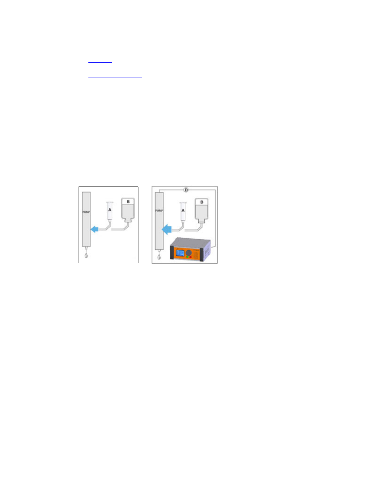
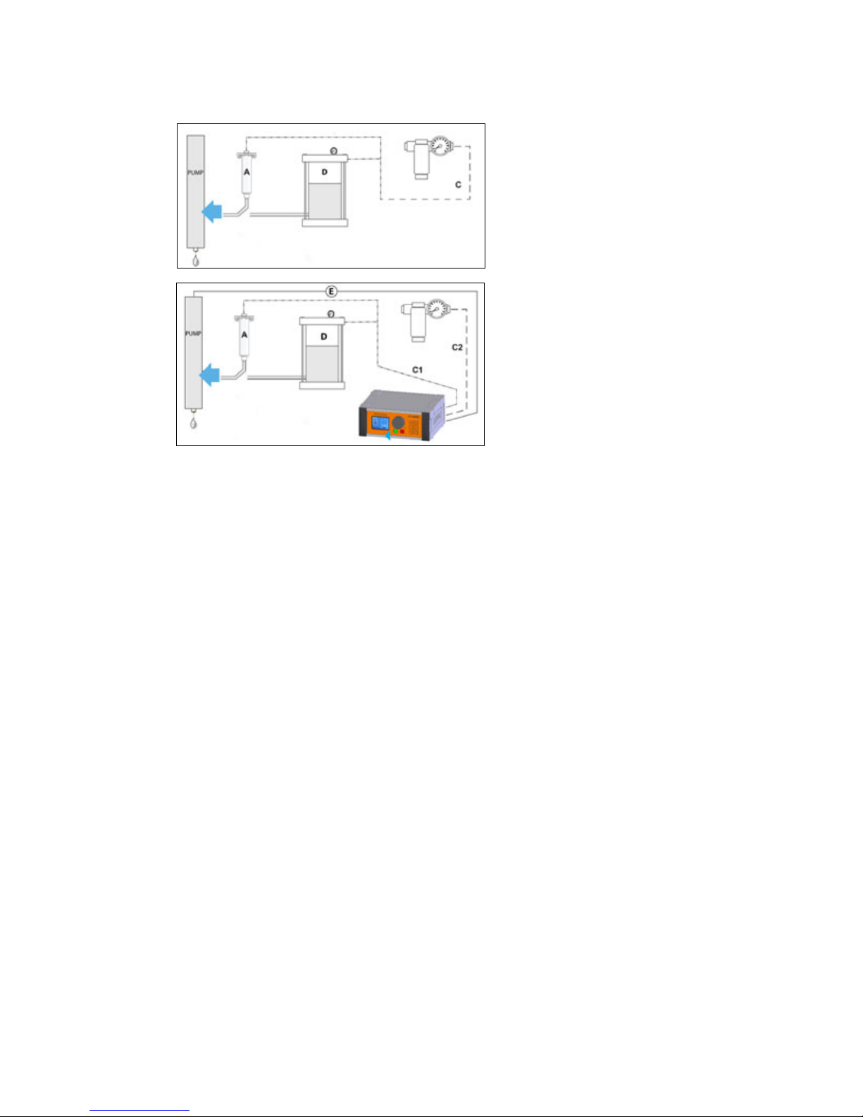
Connection Options
Gravity Fed, Low Viscosity Medium
(pg 32)
(pg 34)
A = supply of medium from a cartridge (A).
B = supply of medium from a bottle (B).
D = Power supply drive unit
Select a size of hose such that the liquid flows out of the dispense pump by gravity without air bubbles.
Self-suction is possible.
2/20/19 GPD Global
®
32
PCD Pump User Guide References
Pressurized, Medium/High Viscosity Medium
A - supply of medium from a cartridge
C - compressed air, 0-7 bar regulated
C1 - compressed air, 0-6 bar regulated.
C2 - Compressed air, 7 bar, dry, clean, oil-free
D - supply of medium from a pressure tank.
E - Power supply drive unit
Compressed air supplies either the cartridge (A) or pressure tank (D).
1 - Cartridge (Item A) supplied with compressed air (C or C1), connected to the dispense pump.
2 - Medium supply from the pressure tank (Item D).
2/20/19 GPD Global
®
33

PCD Pump User Guide References
Assembly Drawings
PCD3 Models
• PCD3 - 10/4807 (pg 35)
• PCD3 - 22293093-1004
– 22293091 replaced by 22293093-1004
• PCD3 - 22293093
• PCD3L - 22293093-1002
– 22293120 replaced by 22293093-1002
• PCD3H - 22293093-1003
– 22293228 replaced by 22293093-1003
• PCD3H legacy - 22293121
• PCD3 Stator End Piece - 22293179
PCD4 Models
• PCD4 - 2650-0048 (pg 42)
• PCD4 - 22293098
• PCD4 - 22293081
• PCD4 - 22293098-0002
• PCD4L - 22293122
• PCD4H - 22293103
• PCD4H - 22293227-0002
• PCD4H - 22293227-0003
• PCD4HB - 22293240
• PCD4HB legacy - 22293205
(pg 36)
(pg 37)
(pg 38)
(pg 39)
(pg 40)
(pg 41)
(pg 43)
(pg 44)
(pg 45)
(pg 46)
(pg 47)
(pg 48)
(pg 49)
(pg 50)
(pg 51)
PCD6 Models
• PCD6 - 22293160 (pg 52)
• PCD6 - 22293161-001
• PCD6HB - 22293161-003
(pg 53)
(pg 54)
PCD7 Models
• PCD7H - 22293306-003 (pg 55)
Related Items
Level Detect
• Level Detect, DS Series - 22110521
• Level Detect, MAX Series - 22293101
Mounting Detail
• Clamp Mount Hole Patterns & Groove - 22212002
• Clamp Mount Dimensions - 22212002
• Taper-Lock Mounting Detail - 22110291
(pg 56)
(pg 57)
(pg 59)
(pg 60)
(pg 58)
2/20/19 GPD Global
®
34

GPD Global
©
PCD3 - 10/4807
2/20/19 PCD Pump User Guide 35
PCD3 - 10/4807
Parts List
DESCRIPTIONPART NUMBERQTYITEM
ORING,VITON,SPECIAL_.25 X .18 X
.035
10/042711
ELBOW,5/32 HOSE10/1804
12
ADAPTER, THD, LUER, FEMALE,
SST,1/4-32
10/317113
COUPLING STAR SHAPED10/4673
14
ASSEMBLY AID HAND DRIVER10/4674
1
5
SET SCREW M3 X 510/467826
O-RING FKM 16MM DIA X 1.2510/4679
17
O-RING FKM 13MM DIA X 1.2510/4683
18
SEAL SET W/HOUSING
10/468619
ALLEN SCREW M3 X 2510/4687
4
10
O-RING NBR 17MM DIA X 1.2510/4691
113
DISPENSING UNIT PCD3 CPL10/4822
114
UNION RING PCD310/4823115
DRIVE UNIT CPL_PCD 310/4826116
O-RING FKM 14MM DIA X 1.510/4829
117
BLEED SCREW PCD310/4830
118
O-RING FKM 8MM DIA X 1.2510/4831119
ALLEN SCREW M3 X 1610/4834
420
PURGE TUBE ASSY PCD VALVES
22110495122
FEED RESERVOIR_PCD
22203375123
DISPENSER HOUSING
PCD3_MODIFIED
22203403124
TUBE SUPPORT_PCD3 PURGE
22203411125
BEARING HOUSING W/ROTOR SET
CPL
22203466126
CAP SCREW, SST, 3MM X 0.5
20MM LG
SACSM030050020
128
STATOR END
PIECE_PCD3_MOD_FEMALE
22203583129
STATOR END
PIECE_PCD3_MOD_MALE
22203584130
THREADED SLEEVE_LUER-LOCK10/4690131
WASHER_TEFLON_.197ID X .280OD
X .015 THICK
2825-0035132
END PIECE_PCD3_STATOR
MOD_ASSY
22293179133
1
1
2
2
3
3
4
4
A A
B B
DWG SIZE
DWG NO
SHEET
OF
DRAWN BY
DESCRIPTION
ASSEMBLY
FINISH
MATERIAL
TOLERANCES UNLESS OTHERWISE SPECIFIED
FRACTIONS B1/32
HEAT TREATMENT
X.XX B0.015
X.XXX
B
0.005
ANGULAR
B
0.5
`
RUNOUT B0.003 T.I.R.
METRIC
0.0 MM
B
0.4 MM
0.00 MM
B
0.1 MM
GPD
Global
VALVE PCD3 W 1 METER CABLE
10_4807
1
1
B
ARM
11/2/2010
0 MM B1.0 MM
REVISION HISTORY
REV DATE BY DESCRIPTION
A6/24/16IHD
REPLACED PART 27, 22293179 WITH CORECTED 22293179 ASSEMBLY, PART 33
22
8
2
23
1
3
28
25
24
19
18
20
17
15
9
7
5
6
10
26
4
13
LAST REVISED 11/10/17
29
32
30
31
16
14
33

GPD Global
©
PCD3 - 22293093-1004
2/20/19 PCD Pump User Guide 36
PCD3 - 22293093-1004
PARTS LIST
DESCRIPTION
PART NUMBER
QTY
ITEM
ELBOW_MALE_M5X4MM TUBE
10/2017
11
ADAPTER, THD, LUER, FEMALE, SST,1/4-3210/3171
1
2
ORING,VITON_5mmID X 1mmW
10/4912
1
3
PURGE TUBE ASSY PCD VALVES2211049514
FEED RESERVOIR_PCD22203375
15
SYRINGE SUPPORT_PCD 450_SNAP STYLE22203379
1
6
MOTOR CLAMP_SYRINGE SUPPORT_PCD 45022203380
17
MALE ADAPTER_PCD322203402
1
8
MOTOR CLAMP_PCD32220340419
TUBE SUPPORT_PCD3 PURGE22203411
1
10
PUMP_PCD3_BASE22293093-0004
111
DISPENSER HOUSING PCD3_MODIFIED22203403111.1
PUMP PCD322293093
1
11.2
COUPLING STAR SHAPED
10/4673
111.2.1
ASSEMBLY AID HAND DRIVER
10/4674
1
11.2.2
SET SCREW M3 X 5
10/4678
211.2.3
SEAL SET W/HOUSING10/4686
111.2.4
ALLEN SCREW M3 X 25
10/4687
4
11.2.5
O-RING NBR 17MM DIA X 1.25
10/4691
111.2.6
WRENCH_HEX-KEY_2.5MM W/HANDLE10/4772
1
11.2.7
UNION RING PCD3
10/4823
1
11.2.8
ALLEN SCREW M3 X 16
10/4834
411.2.9
O-RING_FKM_.547ID X .051W2575-0004
1
11.2.10
O-RING_FKM_.632 ID X .047 SECTION2575-0005
1
11.2.11
O-RING FKM 14MM DIA X 1.52575- 0007111.2.12
BEARING HOUSING W/ROTOR SET CPL
22203466
1
11.2.13
END PIECE_PCD3_STATOR MOD_ASSY22293179111.2.14
THREADED SLEEVE LUER-LOCK10/4690
1
11.2.14.3
WASHER_TEFLON_.197ID X .280OD X .015 THI2825-0035
1
11.2.14.4
STATOR END PIECE_PCD3_MOD_FEMALE22203583111.2.14.1
STATOR END PIECE_PCD3_MOD_MALE22203584
1
11.2.14.2
ASSY_DRIVE UNIT_PCD3_HOUSING22293221111.2.15
WRENCH_HEX-KEY_1.5MM_L SHAPE
M2003
1
11.2.16
DOWEL PIN 1/8 X 1.0 LONG
DA12100
1
12
SCR.A.CP.SST.MET.M3X.5_12MM LGSACSM030050012213
SCR.A.CP.SST.MET.M3X.5_20MM LGSACSM0300500202
14
SCR.A.CP.SST.MET.M3X.5_30MM LGSACSM0300500302
15
1
1
2
2
3
3
4
4
A A
B B
C C
D D
DWG SIZE
DWG NO
SHEET
OF
DRAWN BY
DESCRIPTION
ASSEMBLY
FINISH
MATERIAL
TOLERANCES UNLESS OTHERWISE SPECIFIED
FRACTIONS B1/32
HEAT TREATMENT
X.XX B0.015
X.XXX
B
0.005
ANGULAR
B
0.5
`
RUNOUT B0.003 T.I.R.
METRIC
0.0 MM
B
0.4 MM
0.00 MM
B
0.1 MM
GPD
Global
PUMP_PCD
22293093-1004
1 1
C
MW
9/27/2017
PCD3
ASSEMBLY
0 MMB1.0 MM
REVISION HISTORY
REV DATE BY DESCRIPTION
-- -
ORIGINAL ISSUE
A
6/1/2018
HTB ROTATED THE PUMP VIEW NOZZLE DOWN
13
6
7
14
8
12
11.2.15
11.2.6
9
15
11.2.5
11.2.1
11.2.13
11.2.11
11.2.4
11.2.10
11.1
1
11.2.12
11.2.9
11.2.14.1
11.2.14.2
11.2.14.4
11.2.14.3
11.2.8
2
3
5
4
14
10
11.2.7
11.2.2
11.2.16
11.2.3
2X
4X
4X
2X
2X

GPD Global
©
PCD3 - 22293093
2/20/19 PCD Pump User Guide 37
PCD3 - 22293093
Parts List
DESCRIPTIONPART NUMBERQTYITEM
COUPLING STAR SHAPED10/467311
ASSEMBLY AID HAND DRIVER10/4674
12
SET SCREW M3 X 510/4678
23
SEAL SET W/HOUSING10/468614
ALLEN SCREW M3 X 2510/4687
45
O-RING NBR 17MM DIA X 1.2510/4691
16
WRENCH_HEX-KEY_2.5MM W/HANDLE10/4772
1
7
UNION RING PCD310/482318
DRIVE UNIT CPL PCD310/4826
19
DISPENSER HOUSING PCD310/4828
110
ALLEN SCREW M3 X 16
10/4834411
BEARING HOUSING W/ROTOR SET CPL22203466112
END PIECE_PCD3_STATOR MOD_ASSY
22293179113
ASSY_DRIVE UNIT_PCD3_HOUSING
22293221114
O-RING_FKM_.547ID X .051W2575-0004115
O-RING_FKM_.632 ID X .047 SECTION2575-0005116
O-RING FKM 14MM DIA X 1.5
2575-0007117
WRENCH_HEX-KEY_1.5MM_L SHAPE
M2003118
1
1
2
2
3
3
4
4
A A
B B
DWG SIZE
DWG NO
SHEET
OF
DRAWN BY
DESCRIPTION
ASSEMBLY
FINISH
MATERIAL
TOLERANCES UNLESS OTHERWISE SPECIFIED
FRACTIONS B1/32
HEAT TREATMENT
X.XX B0.015
X.XXX
B
0.005
ANGULAR
B
0.5
`
RUNOUT B0.003 T.I.R.
METRIC
0.0 MM
B
0.4 MM
0.00 MM
B
0.1 MM
GPD
Global
VALVE_PCD3_10" WIRE LENGTH_VER1
22293093
1
1
B
MW
4/13/2011
PUMP_PCD3
10/4807
NA
0 MM B1.0 MM
REVISION HISTORY
REV DATE BY DESCRIPTION
A 8/19/13 BLH 22293179 REPLACED 10/4824 STATOR ASSY
B2/7/14IAH
REMOVED 22203403, ADDED BALLOON FOR 22203401, ADDED PART 22203466
C 7/25/2017 MW ADD STOCK PARTS AND TOOLS TO BOM
NOTES:
1. DISASSEMBLE PUMP 10/4807 RETAINING BOX AND TOOLS.
2. DISCARD O-RINGS INCLUDED WITH PUMP AND USE SPECIFIED O-RINGS ON REASSEMBLY.
3. REPLACE MOTOR HOUSING WITH PN 22203401.
4. MODIFY BEARING HOUSING W/ROTOR SET CPL AS PER DRAWING 22203466.
5. MODIFY AND REPLACE STATOR END PIECE AS PER DRAWING 22293179.
6. REASSEMBLE PUMP AND RETURN TO BOX WITH TOOLS.
7
2
18
6
1
5
12
16
4
15101117138
4X 4X
3 2X
14

GPD Global
©
PCD3L - 22293093-1002
2/20/19 PCD Pump User Guide 38
PCD3L - 22293093-1002
Parts List
DESCRIPTION
PART NUMBER
QTY
ITEM
ELBOW_MALE_M5X4MM TUBE10/2017
11
ADAPTER, THD, LUER, FEMALE, SST,1/4-3210/3171
22
LUER CAP FITTING MALE LOCKING10/4836
13
ORING,VITON_5mmID X 1mmW10/4912
94
PURGE TUBE ASSY PCD VALVES
2211049515
BUSHING,10CC
2214104316
ADAPTER MOUNT_PCD3 VER2
2220343017
CLIP_PURGE VENT_PCD4H
2220345318
SYRINGE TUBE/VENT BLOCK, PCD4H
2220345419
MALE ADAPTER_PCD4H_SHORT CONFIG
22203457110
MOTOR CLAMP_SYRINGE SUPPORT_PCD 450
22203465111
SYRINGE SUPPORT_PCD3L_SNAP STYLE
22203619112
PUMP_PCD3L BASE
22293093-0002113
DISPENSER HOUSING_PCD3_MODIFIED
22203474113.1
SCR.A.CP.SST.MET.M3X.5_25MM LGSACSM030050025
413.2
VALVE_PCD3L
22293093113.3
COUPLING STAR SHAPED10/4673
113.3.1
SET SCREW M3 X 510/4678
213.3.2
O-RING NBR 17MM DIA X 1.2510/4691
113.3.3
ALLEN SCREW M3 X 2510/4687
413.3.4
UNION RING PCD310/4823
113.3.5
SEAL SET W/HOUSING10/4686
113.3.6
END PIECE_PCD3_STATOR MOD_ASSY
22293179113.3.7
STATOR END PIECE_PCD3_MOD_FEMALE
22203583113.3.7.1
STATOR END PIECE_PCD3_MOD_MALE
22203584113.3.7.2
THREADED SLEEVE LUER-LOCK10/4690
113.3.7.3
WASHER_TEFLON_.197ID X .280OD X .015 THI
2825-0035113.3.7.4
BEARING HOUSING W/ROTOR SET CPL
22203466113.3.8
O-RING_FKM_.632 ID X .047 SECTION
2575-0005113.3.9
O-RING_FKM_.547ID X .051W
2575-0004113.3.10
O-RING FKM 14MM DIA X 1.5
2575-0007113.3.11
ASSEMBLY AID HAND DRIVER10/4674
113.3.12
WRENCH_HEX-KEY_1.5MM_L SHAPEM2003113.3.13
WRENCH_HEX-KEY_2.5MM W/HANDLE10/4772113.3.14
ASSY_DRIVE UNIT_PCD3_HOUSING22293221113.3.15
DOWEL PIN 3mm X 8mmDAM03008314
DOWEL PIN 5mm X 10mmDAM05010115
SCR.A.CP.SST.MET.M2X.4_10MM LGSACSM020040010216
SCR.A.CP.SST.MET.M3X.5_6MM LGSACSM030050006617
SCR.A.CP.SST.MET.M3X.5_12MM LGSACSM030050012219
SCR.A.CP.SST.MET.M3X.5_16MM LGSACSM030050016120
SCREW,FLATHEAD,4MM X 18LG ALLOYSAFANM040070018121
1
1
2
2
3
3
4
4
A A
B B
C C
D D
DWG NO
SHEET
OF
DRAWN BY
DESCRIPTION
ASSEMBLY
MATERIAL
GPD
Global
PUMP_PCD3L
22293093-1002
1 1
MW
9/22/2017
PUMP PCD
ASSEMBLY
REVISION HISTORY
REV DATE BY DESCRIPTION
A 12/7/2017 MW SCREW WAS 4X SACSM030050008 IS 4X SACSM030050006
13.3.12
13.3.13
13.3.14
21
10
177
19
12
6
13.3.15
13.3.3
13.3.4
13.3.1
13.3.8
13.3.2
13.3.9
13.3.6
13.3.10
15
13.2
13.3.11
13.3.7.1
13.3.7.2
13.3.7.4
13.3.7.3
13.3.5
13.1
14
1618
5
17
2
3
2
4
11
20
14
2X
3X
2X
4X
4X
4X
9

GPD Global
©
PCD3H - 22293093-1003
2/20/19 PCD Pump User Guide 39
PCD3H - 22293093-1003
Parts List
DESCRIPTION
PART NUMBER
QTY
ITEM
ELBOW_MALE_M5X4MM TUBE
10/2017
11
ADAPTER, THD, LUER, FEMALE, SST,1/4-3210/317122
LUER CAP FITTING MALE LOCKING
10/4836
1
3
ORING,VITON_5mmID X 1mmW
10/4912
34
PURGE TUBE ASSY PCD VALVES22110495
15
BUSHING,10CC22141043
1
6
ADAPTER MOUNT_PCD3 VER222203430
17
SUPPORT TAB_LUER FITTING_PCD4H22203453
1
8
SYRINGE TUBE/VENT BLOCK, PCD4H
2220345419
MALE ADAPTER_PCD4H_SHORT CONFIG22203457
1
10
SYRINGE SUPPORT_PCD_SNAPSTYLE_RND22203606
111
PUMP_PCD3H BASE22293093-0003112
PUMP PCD3H22293093
1
12.1
COUPLING STAR SHAPED
10/4673
112.1.1
ASSEMBLY AID HAND DRIVER
10/4674
1
12.1.12
SET SCREW M3 X 5
10/4678
212.1.2
SEAL SET W/HOUSING10/4686
112.1.6
ALLEN SCREW M3 X 25
10/4687
4
12.1.4
WRENCH_HEX-KEY_2.5MM W/HANDLE10/4772
112.1.14
UNION RING PCD310/4823
1
12.1.5
BEARING HOUSING W/ROTOR SET CPL
22203466
1
12.1.8
END PIECE_PCD3_STATOR MOD_ASSY22293179112.1.7
O-RING_FKM_.547ID X .051W2575-0004
1
12.1.10
O-RING_FKM_.632 ID X .047 SECTION2575-0005
1
12.1.9
O-RING FKM 14MM DIA X 1.52575-0007112.1.11
WRENCH_HEX-KEY_1.5MM_L SHAPEM2003
1
12.1.13
DISPENSER HOUSING_PCD3_MODIFIED22203474112.2
SCR.A.CP.SST.MET.M3X.5_25MM LGSACSM030050025
4
12.3
SCR.A.CP.SST.MET.M2X.4_14MM LGSACSM020040014312.4
BODY ADAPTER_MICRO MOTOR ADAPTER22203605112.5
DOWEL PIN 2mm X 6mmDAM02006
1
12.6
DOWEL PIN 3mm X 8mmDAM03008212.7
COUPLER,6MM22203421
1
12.8
DEVICE_MOTOR_SERVO_20 PIN CONNECTOR22293288
1
12.9
SET.A.CU.SST.MET_ 3MMX0.5 X 3MM LG SSTTACSM030050003112.10
DOWEL PIN 3mm X 8mmDAM03008213
SCR.A.CP.SST.MET.M2X.4_10MM LGSACSM0200400102
14
SCR.A.CP.SST.MET.M3X.5_8MM LGSACSM030050008
615
SCREW,FLATHEAD,4MM X 18LG ALLOYSAFANM040070018
1
16
1
1
2
2
3
3
4
4
A A
B B
C C
D D
DRAWING NUMBER
SHEET OF
DRAWN BY:
DESCRIPTION:
ASSEMBLY:
PUMP_PCD3H
22293093-1003
1 1
ARM
8/14/2017
DATE:
MOUNT BLEED TUBE
ON THESE HOLES
REVISION HISTORY
REV BY DATE DESCRIPTION
A MW 11/14/2017 UPDATE CHANGES TO 22293093-0003
12.9
12.5
12.7
12.4
16
7 15
12.1.6
12.1.10
12.2
12.1.11
12.3
12.1.7
12.1.5
10
14
18
5
15
4
3
2
13
12.1.9
12.1.8
12.1.2
12.1.1
12.1.4
6
11
12.6
3X
4X
3X
2X
2X
3X
4X
2X
9
12.8
12.10
12.1.14
12.1.13
12.1.12

GPD Global
©
PCD3H legacy - 22293121
2/20/19 PCD Pump User Guide 40
PCD3H legacy - 22293121
Parts List
DESCRIPTION
PART NUMBER
QTY
ITEM
ELBOW_MALE_M5X4MM TUBE10/2017
11
ADAPTER, THD, LUER, FEMALE, SST,1/4-3210/3171
22
LUER CAP FITTING MALE LOCKING10/4836
13
ORING,VITON_5mmID X 1mmW10/4912
34
PURGE TUBE ASSY PCD VALVES
2211049515
MOTOR/GEARBOX ASSEMBLY
2214103316
BUSHING,10CC
2214104317
COUPLER,6MM
2220342118
ADAPTER MOUNT_PCD3 VER2
2220343019
SYRINGE SUPPORT_PCD4H_SNAP STYLE
22203448110
BODY ADAPTER_PCD4H MOTOR INTERFACE
22203449111
SUPPORT TAB_LUER FITTING_PCD4H
22203453112
SYRINGE TUBE/VENT BLOCK, PCD4H
22203454113
MALE ADAPTER_PCD4H_SHORT CONFIG
22203457114
DISPENSER HOUSING_PCD3_MODIFIED
22203474115
PUMP PCD3 LEGACY
22293093116
COUPLING STAR SHAPED10/4673
116.1
SET SCREW M3 X 510/4678
216.2
O-RING NBR 17MM DIA X 1.2510/4691
116.3
ALLEN SCREW M3 X 2510/4687
416.4
UNION RING PCD310/4823
116.5
SEAL SET W/HOUSING10/4686
116.6
END PIECE_PCD3_STATOR MOD_ASSY
22293179116.7
STATOR END PIECE_PCD3_MOD_FEMALE
22203583116.7.1
STATOR END PIECE_PCD3_MOD_MALE
22203584116.7.2
THREADED SLEEVE LUER-LOCK10/4690
116.7.3
WASHER_TEFLON_.197ID X .280OD X .015 THI
2825-0035116.7.4
BEARING HOUSING W/ROTOR SET CPL
22203466116.8
O-RING_FKM_.632 ID X .047 SECTION
2575-0005116.9
O-RING_FKM_.547ID X .051W
2575-0004116.10
O-RING FKM 14MM DIA X 1.5
2575-0007116.11
ASSEMBLY AID HAND DRIVER10/4674
116.12
WRENCH_HEX-KEY_1.5MM_L SHAPEM2003116.13
WRENCH_HEX-KEY_2.5MM W/HANDLE10/4772116.14
DOWEL PIN 3mm X 8mmDAM03008
4
17
SCR.A.BH.SST.MET.M3X.5_6MM LGSABSM030050006
4
18
SCR.A.CP.SST.MET.M2X.4_10MM LGSACSM020040010219
SCR.A.CP.SST.MET.M3X.5_8MM LGSACSM030050008620
SCR.A.CP.SST.MET.M3X.5_25MM LGSACSM030050025
4
21
SCREW,FLATHEAD,4MM X 18LG ALLOYSAFANM040070018122
SET.A.CU.SST.MET_ 3MMX0.5 X 3MM LG SSTTACSM030050003123
1
1
2
2
3
3
4
4
A A
B B
C C
D D
DRAWING NUMBER
SHEET OF
DRAWN BY:
DESCRIPTION:
ASSEMBLY:
PUMP_PCD3H
22293121
1 1
ARM
7/7/2011
DATE:
MOUNT BLEED TUBE
ON THESE HOLES
REVISION HISTORY
REV BY DATE DESCRIPTION
-
ARM 7/7/2011 ORIGINAL ISSUE
A BLH 9/7/2012 2575-0004 & 2575-0005 WERE 10/4679 & 10/4683
B BLH 10/1/12 10/4912 REPLACED ALL 10/0427
C BLH 10/5/12
10/4824 IS ASSY OF 10/4825 & 10/4690, 10/2017 REPLACED 10/1804
D BLH 12/2/12 2575-0006 & 2575-0007 WERE 10/4689 &10/4829
E BLH 7/19/13
1)3500-0091 REPLACED 22141058 MOTOR, 22203606 REPLACED
22203448 2) 22293179 REPLACED 10/4824 3) REMOVED 2575-0006
F IAH 4/17/15 UPDATED TO ORIGINAL MOTOR
G IHD 6/24/16
REPLACED PART 10 10_4824 WITH PARTS 35, 36, 37, 38, 39.
HMW 7/27/17
PUMP PART OF ASSY 22293093-0003; REDRAW DELETE SHEET 2& 3
J
MW 11/10/2017
RENUMBERED PARTS, GROUPED SUB ASSEMBLIES
16.3
10
7
16.1
16.4
16.2
16.8
9
20
14
22
16.9
16.5
16.7.3
16.7.4
16.7.2
16.7.1
16.11
16.6
3
2 17 4
2
20
13512 191
16.12
16.13
16.14
16.10
4X
2X
3X 2X
2X
2X
23
17
18
11
6
8
4X
2X
15
4X
21
4X

GPD Global
©
PCD3 Stator End Piece - 22293179
2/20/19 PCD Pump User Guide 41
PCD3 Stator End Piece - 22293179
Parts List
DESCRIPTIONPART NUMBERQTYITEM
STATOR END PIECE_PCD3_MOD_FEMALE
2220358311
STATOR END PIECE_PCD3_MOD_MALE2220358412
THREADED SLEEVE LUER-LOCK10/4690
13
WASHER_TEFLON_.197ID X .280 OD X .015 THI2825-003514
1
2
3
4
DWG SIZE
DWG NO
SHEET
OF
DRAWN BY
DESCRIPTION
ASSEMBLY
FINISH
MATERIAL
TOLERANCES UNLESS OTHERWISE SPECIFIED
FRACTIONS B1/32
HEAT TREATMENT
X.XX B0.015
X.XXX B0.005
ANGULAR
B0.5`
RUNOUT B0.003 T.I.R.
METRIC
0.0 MM B0.4 MM
0.00 MM B0.1 MM
GPD
Global
END PIECE_PCD3_STATOR MOD_ASSY
22293179
1 1
B
BLH
6/14/2013
PCD3
NOTED
N/A
0 MM B1.0 MM
REVISION HISTORY
REV DATE BY DESCRIPTION
-- -
ORIGINAL ISSUE
NONE
NOTES UNLESS OTHERWISE SPECI FIED:
1. EDGE BREAK ALL CORNERS, EDGES AND HOLES:
.005/.015 FOR MATERIAL >= .100 THICK
5%/15% OF THICKNESS FOR MATERIA L < .100 THICK
2. .015 MAXIMUM FILLET
3. 64 MACHINE FINISH OR BETTER
4. ALL DIMENSIONS ARE PRE-PLATE (IF APPLIED)
5. PLATING THICKNESS IS PER SIDE (IF APPLIED)
6. REMOVE RAW STOCK LETTERING, LINEAR GRAIN, OR MATERIAL REMOVAL
4
1
3
2

GPD Global
©
PCD4 - 2650-0048
2/20/19 PCD Pump User Guide 42
PCD4 - 2650-0048
Parts List
DESCRIPTION
PART NUMBER
QTY
ITEM
COUPLING STAR SHAPED10/4673
11
ASSEMBLY AID / HAND DRIVER10/467412
STATOR CPL_PCD410/4675
13
O-RING_FKM_.632 ID X .047
SECTION
2575-000514
ALLEN SCREW M3 X 2010/46804
5
O-RING FKM 15MM DIA X 1.510/468216
ALLEN SCREW M3 X 610/46841
7
WASHER A 3.210/4685
18
ALLEN SCREW M3 X 2510/4687
49
O-RING NBR 17MM DIA X 1.2510/4691
110
UNION RING PCD410/4803
111
THREADED SLEEVE LUER-LOCK10/4804
112
END PIECE PCD4 W/LUER-LOCK
OEM
10/4805113
DISPENSING UNIT PCD4 CPL.
(WITHOUT 20)
10/4817
114
END PIECE PCD4 WITH
LUER-LOCK CPL.
10/4818115
BEARING HOUSING W/ROTOR
SET CPL
10/4820
116
SEAL SET W/HOUSING10/4821
117
O-RING_FKM_.547ID X .051W
2575-0004118
O-RING_FKM_.110 ID X .028
SECTION
2575-0006119
DISPENSER
HOUSING_PCD4_SIDE PURGE
2650-0049120
DRIVE UNIT CPL PCD4 INCL 9 & 12650-0050121
1
1
2
2
3
3
4
4
A A
B B
DWG SIZE
DWG NO
SHEET
OF
DRAWN BY
DESCRIPTION
ASSEMBLY
FINISH
MATERIAL
TOLERANCES UNLESS OTHERWISE SPECIFIED
FRACTIONS B 1/32
HEAT TREATMENT
X.XX B 0.015
X.XXX
B 0.005
ANGULAR
B 0.5`
RUNOUT B 0.003 T.I.R.
METRIC
0.0 MM
B 0.4 MM
0.00 MM
B 0.1 MM
GPD
Global
VALVE PCD4 250MM CABLE_VER2
2650-0048
1
1
B
ARM
2/1/2012
0 MM B 1.0 MM
21
15
14
REVISION HISTORY
REV DATE BY DESCRIPTION
A
6/24/2016 IHD
REPLACED PARTS 4, 18 WITH CORECTED O-RINGS
10
7
8
20
6
5
3
13
19
11
12
1
9
16
17
2
LAST REVISED 5/4/15
18
4

GPD Global
©
PCD4 - 22293098
2/20/19 PCD Pump User Guide 43
PCD4 - 22293098
Parts List
PART NUMBER
QTY
ITEM
2230303911
10/3171
12
2214104313
2220337514
222035231
5
2650-004816
10/4912
1
7
SACSM030050010
28
DESCRIPTION
MOUNTING DISPENSE_TABBED_PCD ORANGE
ADAPTER, THD, LUER, FEMALE, SST,1/4-32
BUSHING,10CC
FEED RESERVOIR_PCD
SYRINGE SUPPORT_PCD_VER2_STRAIGHT
VALVE PCD4 250MM CABLE_VER2
ORING,VITON_5mmID X 1mmW
CAP SCREW 3MM X 0.5 X 10MM LG
CAP SCREW 4MM X 0.7 - 10MM LGSACAM0040070010
19
1
2
3
4
DWG SIZE
DWG NO
SHEET
OF
DRAWN BY
DESCRIPTION
ASSEMBLY
FINISH
MATERIAL
TOLERANCES UNLESS OTHERWISE SPECIFIED
FRACTIONS B 1/32
HEAT TREATMENT
X.XX B 0.015
X.XXX
B 0.005
ANGULAR
B 0.5`
RUNOUT B0.003 T.I.R.
METRIC
0.0 MM
B 0.4 MM
0.00 MM
B 0.1 MM
GPD
Global
PUMP_PCD4_TABLETOP/STANDALONE
22293098
1
1
B
BLH
3/13/2013
PCD4
NOTED
N/A
0 MM B1.0 MM
REVISION HISTORY
REV DATE BY DESCRIPTION
-- -
ORIGIN
A
LISSUE
NONE
6
8
5
2
7
4
1
3
9

GPD Global
©
PCD4 - 22293081
2/20/19 PCD Pump User Guide 44
PCD4 - 22293081
Parts List
DESCRIPTION
PART NUMBER
QTY
ITEM
ADAPTER, THD, LUER, FEMALE, SST,1/4-3210/3171
11
VALVE PCD4 250MM CABLE_VER2
2650-004812
FEED RESERVOIR
2220337513
VALVE_PCD4 HALF CLAMP
2220338514
MALE ADAPTER_PCD4
222033891
5
DOWEL PIN 3mm X 20mm
DAM0302026
CAP SCREW 3MM X 0.5 20MM LGSACSM030050020
2
7
SET SCREW 3MMX0.5 X 5MM LG ALLOYTACAM030050005
28
LEVEL DETECT_PCD_VER2_CAPACITAN
2229310119
ORING,VITON_5mmID X 1mmW10/4912
110
SYRINGE SUPPORT_PCD_VER2_STRAIGHT
22203523111
CAP SCREW 3MM X 0.5 X 10MM LGSACSM030050010
212
1
2
3
4
DWG SIZE
DWG NO
SHEET
OF
DRAWN BY
DESCRIPTION
ASSEMBLY
FINISH
MATERIAL
TOLERANCES UNLESS OTHERWISE SPECIFIED
FRACTIONS B 1/32
HEAT TREATMENT
X.XX B 0.015
X.XXX
B 0.005
ANGULAR
B 0.5`
RUNOUT B0.003 T.I.R.
METRIC
0.0 MM
B 0.4 MM
0.00 MM
B 0.1 MM
GPD
Global
Valve_PCD4
22293081
1
2
B
ARM
8/23/2010
VALVE INTEGRATION
N/A
0 MM B1.0 MM
REVISION HISTORY
REV DATE BY DESCRIPTION
-- - A 11/2/12 BLH 10/4912 WAS 10/0427
B3/13/13 BLH
22203523 SYRINGE SUPPORT REPLACED 22203379,22203386,
2
1
10
3
4
5
NOTE:
ALL FASTENERS STAINLESS STEEL OR PLATED ALLOY
7
6
8
NONE
11
12
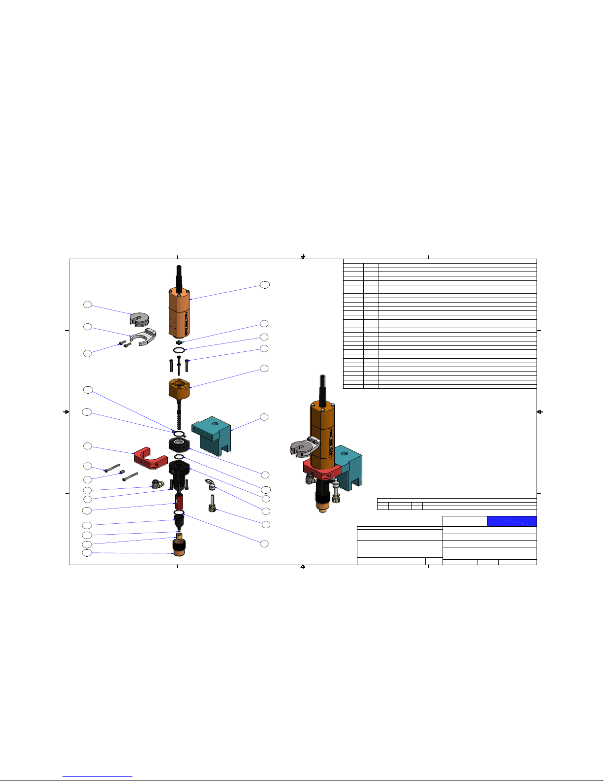
GPD Global
©
PCD4 - 22293098-0002
2/20/19 PCD Pump User Guide 45
PCD4 - 22293098-0002
Parts List
DESCRIPTION
PART NUMBER
QTY
ITEM
ELBOW_MALE_M5X4MM TUBE10/2017
11
PURGE TUBE ASSY PCD VALVES
2211049512
BUSHING_6MM
22141043-000113
SYRINGE SUPPORT_PCD_VER2_STRAIGHT
2220352314
DISPENSER HOUSING_PCD4_ PURGE_MOD
2220377215
CLAMP_MOUNTING_PCD4
2310300116
CLAMP BASE_MOUNTING_PCD4
2310300217
VALVE PCD4 250MM CABLE_VER2
2650-004818
BEARING HOUSING W/ROTOR SET CPL10/4820
18.1
COUPLING STAR SHAPED10/4673
18.2
SEAL SET W/HOUSING10/4821
18.3
O-RING NBR 17MM DIA X 1.2510/4691
18.4
O-RING FKM 15MM DIA X 1.510/4682
18.5
ALLEN SCREW M3 X 2510/4687
48.6
ALLEN SCREW M3 X 2010/4680
48.7
STATOR CPL_PCD410/4675
18.10
THREADED SLEEVE LUER-LOCK10/4804
18.11
UNION RING PCD4 (REPLACES 10/4803)
2220361018.12
END PIECE PCD4 W/LUER-LOCK OEM10/4805
18.13
DRIVE UNIT CPL PCD4
2650-005018.15
O-RING_FKM_.110 ID X .028 SECTION
2575-000618.16
O-RING_FKM_.547ID X .051W
2575-000418.17
O-RING_FKM_.632 ID X .047 SECTION
2575-000518.18
SET SCREW M3 X 510/4678
28.20
FITTING_ELBOW_1/8 UNI_6MM ONE-TOUCH
2675-021219
SCR.A.CP.SST.MET.M3X.5_10MM LGSACSM030050010
210
SCR.A.CP.SST.MET.M3X.5_30MM LGSACSM030050030
211
SET.A.CU.SST.MET_ 5MMX0.8 X 8MM LG SSTTACSM050080008
112
1
1
2
2
3
3
4
4
A A
B B
C C
D D
DWG SIZE
DWG NO
SHEET
OF
DRAWN BY
DESCRIPTION
ASSEMBLY
FINISH
MATERIAL
TOLERANCES UNLESS OTHERWISE SPECIFIED
FRACTIONS B1/32
HEAT TREATMENT
X.XX B0.015
X.XXX
B
0.005
ANGULAR
B
0.5
`
RUNOUT B0.003 T.I.R.
METRIC
0.0 MM
B
0.4 MM
0.00 MM
B
0.1 MM
GPD
Global
PUMP_PCD4_CONFORMAL COAT CONFIG
22293098-0002
1 1
C
MW
5/31/2017
PCD4
NOTED
N/A
0 MMB1.0 MM
REVISION HISTORY
REV DATE BY DESCRIPTION
A 9/13/2017 MW ADDED PURGE TUBE ASSEMBLY AND 22203772
NONE
4
3
8.15
8.2
8.4
8.6
8.1
7
8.3
8.17
8.7
8.10
8.13
8.16
8.11
8.12
11
9
6
10
8.18
8.5
4X
2X
2X
4X
12
5
1
2
8.20
NOTE: PN 2650-0049, 10/4684, AND 10/4685 FROM PN 2650-0048 ARE NOT
USED IN THIS ASSEMBLY. RETURNED UNUSED PARTS TO STORES.
2X

GPD Global
©
PCD4L - 22293122
2/20/19 PCD Pump User Guide 46
PCD4L - 22293122
Parts List
DESCRIPTION
PART NUMBER
QTY
ITEM
ELBOW_MALE_M5X4MM TUBE10/2017
11
ADAPTER, THD, LUER, FEMALE, SST,1/4-3210/3171
22
COUPLING STAR SHAPED10/4673
13
STATOR CPL_PCD410/4675
14
SET SCREW M3 X 510/4678
2
5
O-RING FKM 15MM DIA X 1.510/4682
16
ALLEN SCREW M3 X 2510/4687
4
7
UNION RING PCD410/4803
18
THREADED SLEEVE LUER-LOCK10/4804
19
BEARING HOUSING W/ROTOR SET CPL10/4820
110
SEAL SET W/HOUSING10/4821
111
LUER CAP FITTING MALE LOCKING
10/4836112
ORING,VITON_5mmID X 1mmW10/4912
913
PURGE TUBE ASSY PCD VALVES
22110485114
BUSHING,10CC
22141043115
ADAPTER MOUNT_PCD3 VER2
22203430116
VALVE SECTION_PCD4H
22203443117
END SECTION_PCD4H_W/6% TAPER
22203447118
CLIP_PURGE VENT_PCD4H
22203453119
SYRINGE TUBE/VENT BLOCK, PCD4H
22203454120
MOUNT BLOCK_MALE ADAPTER_PCD4H
22203480121
SYRINGE SUPPORT_SNAP STYLE
22203524122
O-RING_FKM_.547ID X .051W
2575-0004123
O-RING_FKM_.632 ID X .047 SECTION
2575-0005124
DRIVE UNIT CPL PCD4
2650-0050125
DOWEL PIN 3mm X 8mm
DAM03008226
DOWEL PIN 5mm X 10mm
DAM05010127
CAP SCREW 3MM X 0.5 - 8MM LGSACAM030050008
628
CAP SCREW 2MM X .04 10MM LG, SSTSACSM020040010
229
CAP SCREW 3MM X 0.5 X 10MM LGSACSM030050010
230
CAP SCREW 3MM X .05 40MM LGSACSM030050040
431
SCREW,FLATHEAD,4MM X 18LG ALLOYSAFANM040070018
132
1234
A A
B B
C C
D D
DRAWING NUMBER
SHEET OF
DRAWN BY:
DESCRIPTION:
ASSEMBLY:
PUMP, PCD4L
22293122
1 2
ALJ
7/7/2011
DATE:
REVISION HISTORY
REV B DATE DESCRIPTION
-
ALJ
7/7/2011 ORIGINAL ISSUE
A BLH 9/7/2012
2575-0004 & 2575-0005 WERE 10/4679 & 10/4683
B BLH 9/26/2012
22110495 WAS 22110485, 10/4912 REPLACED ALL 10/0427
MOUNT BLEED TUBE
ON THESE HOLES
22
30
15
2
12
3
7
10
5
24
11
13
19
29
14
20
28
26
17
16
1
23
31
32
21
27
8
18
9
6
4
25
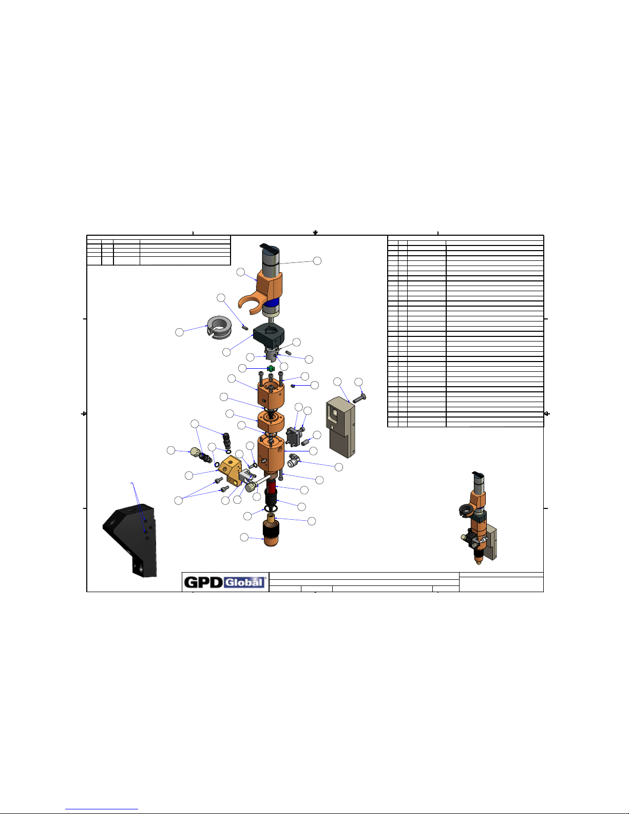
GPD Global
©
PCD4H - 22293103
2/20/19 PCD Pump User Guide 47
PCD4H - 22293103
Parts List
DESCRIPTION
PART NUMBER
QTY
ITEM
ELBOW_MALE_M5X4MM TUBE10/2017
11
ADAPTER, THD, LUER, FEMALE, SST,1/4-3210/3171
22
COUPLING STAR SHAPED10/4673
13
STATOR CPL_PCD410/4675
14
SET SCREW M3 X 510/4678
2
5
O-RING FKM 15MM DIA X 1.510/4682
16
ALLEN SCREW M3 X 2510/4687
4
7
UNION RING PCD410/4803
18
THREADED SLEEVE LUER-LOCK10/4804
19
BEARING HOUSING W/ROTOR SET CPL10/4820
110
SEAL SET W/HOUSING10/4821
111
LUER CAP FITTING MALE LOCKING
10/4836112
ORING,VITON_5mmID X 1mmW10/4912
913
PURGE TUBE ASSY PCD VALVES
22110485114
BUSHING,10CC
22141043115
COUPLER,6MM
22203421117
ADAPTER MOUNT_PCD3 VER2
22203430118
VALVE SECTION_PCD4H
22203443119
END SECTION_PCD4H_W/6% TAPER
22203447120
CLIP_PURGE VENT_PCD4H
22203453123
SYRINGE TUBE/VENT BLOCK, PCD4H
22203454124
MOUNT BLOCK_MALE ADAPTER_PCD4H
22203480125
BODY ADAPTER_MICRO MOTOR ADAPTER
22203605126
SYRINGE SUPPORT_PCD_SNAPSTYLE_RND
22203606127
O-RING_FKM_.547ID X .051W
2575-0004128
O-RING_FKM_.632 ID X .047 SECTION
2575-0005129
MOTOR_GEAR_24VDC_W/ENCODER_DIFFERENTIAL
3500-0094130
DOWEL PIN 2mm X 4mm
DAM02004131
DOWEL PIN 3mm X 8mm
DAM03008432
DOWEL PIN 5mm X 10mm
DAM05010133
CAP SCREW 3MM X 0.5 - 8MM LGSACAM030050008
634
CAP SCREW 2MM X .04 6MM LG, SSTSACSM0020040012
335
CAP SCREW 2MM X .04 10MM LG, SSTSACSM020040010
236
CAP SCREW 3MM X .05 40MM LGSACSM030050040
437
SCREW,FLATHEAD,4MM X 18LG ALLOYSAFANM040070018
138
SET SCREW 3MMX.5 X 3MM LG SSTTACSM030050003
139
1234
A A
B B
C C
D D
DRAWING NUMBER
SHEET OF
DRAWN BY:
DESCRIPTION:
ASSEMBLY:
PUMP, PCD4H
22293103
1 2
ALJ
3/16/2011
DATE:
27
37
15
26
17
3
7
10
11
25
18
1
13
12
2
13
24
4
20
6
8
19
9
14
23
5
34
31
32
32
33
REVISION HISTORY
REV BY DATE DESCRIPTION
-
ALJ
3/16/2011 ORIGINAL ISSUE
A ARM 9/01/2011 22203480 WAS 22203446
B BLH 9/07/2012 2575-0004 & 2575-0005 WERE 10/4679 & 10/4683
C BLH 7/23/13
3500-0091 REPLACED 22141058 MOTOR,
22203606 REPL
A
CED 22203448
39
36
34
38
MOUNT BLEED TUBE
ON THESE HOLES
29
28
30
35

GPD Global
©
PCD4H - 22293227-0002
2/20/19 PCD Pump User Guide 48
PCD4H - 22293227-0002
Parts List
DESCRIPTION
PART NUMBER
QTY
ITEM
ELBOW_MALE_M5X4MM TUBE10/2017
11
ADAPTER, THD, LUER, FEMALE, SST,1/4-3210/3171
22
LUER CAP FITTING MALE LOCKING10/4836
13
ORING,VITON_5mmID X 1mmW10/4912
34
PURGE TUBE ASSY PCD VALVES
2211048515
ADAPTER MOUNT_PCD3 VER2
2220343016
SUPPORT TAB_LUER FITTING_PCD4H
2220345317
SYRINGE TUBE/VENT BLOCK, PCD4H
2220345418
MOUNT BLOCK_MALE ADAPTER_PCD4H
2220348019
SYRINGE SUPPORT_PCD_SNAPSTYLE_RND
22203606110
PUMP_PCD4H_SERVO MOTOR_BASE
22293311-0003111
COUPLER,6MM
22203421111-1
VALVE SECTION_PCD4H
22203443111-2
BODY ADAPTER_MICRO MOTOR ADAPTER
22203738111-3
DEVICE_MOTOR_SERVO_20 PIN CONNECTOR
22293288111-4
DEVICE_MOTOR_SERVO_20 PIN CONNECTOR
22293288111-4-1
STRAIN RELIEF_MOTOR_GEAR
22703040111-4-2
O-RING_FKM_.547ID X .051W
2575-0004111-5
O-RING_FKM_.632 ID X .047 SECTION
2575-0005111-6
O-RING FKM 14MM DIA X 1.5
2575-0007111-7
VALVE PCD4
2650-0048111-8
COUPLING STAR SHAPED10/4673
111-8-1
ASSEMBLY AID HAND DRIVER10/4674
111-8-2
STATOR CPL_PCD410/4675
111-8-3
SET SCREW M3 X 510/4678
211-8-4
ALLEN SCREW M3 X 2510/4687
411-8-5
WRENCH_HEX-KEY_2.5MM W/HANDLE10/4772
111-8-6
UNION RING PCD4 (REPLACES 10/4803)
22203610111-8-7
THREADED SLEEVE LUER-LOCK10/4804
111-8-8
BEARING HOUSING W/ROTOR SET CPL10/4820
111-8-9
SEAL SET W/HOUSING10/4821
111-8-10
WRENCH_HEX-KEY_1.5MM_L SHAPE
M2003111-8-11
DOWEL PIN 2mm X 4mmDAM02004111-9
SCR.A.CP.SST.MET.M2X.4_12MM LGSACSM020040012311-10
SCR.A.CP.SST.MET.M3X.5_40MM LGSACSM030050040
4
11-11
SET.A.CU.SST.MET_ 3MMX0.5 X 3MM LG SSTTACSM030050003111-12
END SECTION_PCD4H_W/6% TAPER22203447111-19
DOWEL PIN 3mm X 8mmDAM03008212
DOWEL PIN 5mm X 10mmDAM05010113
SCR.A.CP.SST.MET.M2X.4_10MM LGSACSM020040010214
SCR.A.CP.SST.MET.M3X.5_8MM LGSACSM030050008615
SCREW,FLATHEAD,4MM X 18LG ALLOYSAFANM040070018116
1
1
2
2
3
3
4
4
A A
B B
C C
D D
DWG SIZE
DWG NO
SHEET
OF
DRAWN BY
DESCRIPTION
ASSEMBLY
FINISH
MATERIAL
TOLERANCES UNLESS OTHERWISE SPECIFIED
FRACTIONS B1/32
HEAT TREATMENT
X.XX B0.015
X.XXX
B
0.005
ANGULAR
B
0.5
`
RUNOUT B0.003 T.I.R.
METRIC
0.0 MM
B
0.4 MM
0.00 MM
B
0.1 MM
GPD
Global
PUMP_PCD4H_SERVO MOTOR
22293227-0002
1 1
C
MW
11/21/2016
PCD4 PUMP
ASSEMBLY
NA
0 MMB1.0 MM
16
9
6
13
1
5
14
7
15
3
2
4
2
12
4
8
15
2X
2X
2X
4X
LAST MODIFIED 11/10/2017
11-11
11-8-3
11-8-7
11-2
11-6
11-8-5
11-1
11-9
11-8-1
11-8-9
11-5
11-8-10
11-8-8
11-8-6
11-8-2
11-8-11
11-10
11-3
10
11-4-1
11-4-2
11-8-4
11-19
11-12
2X
11-7
2X
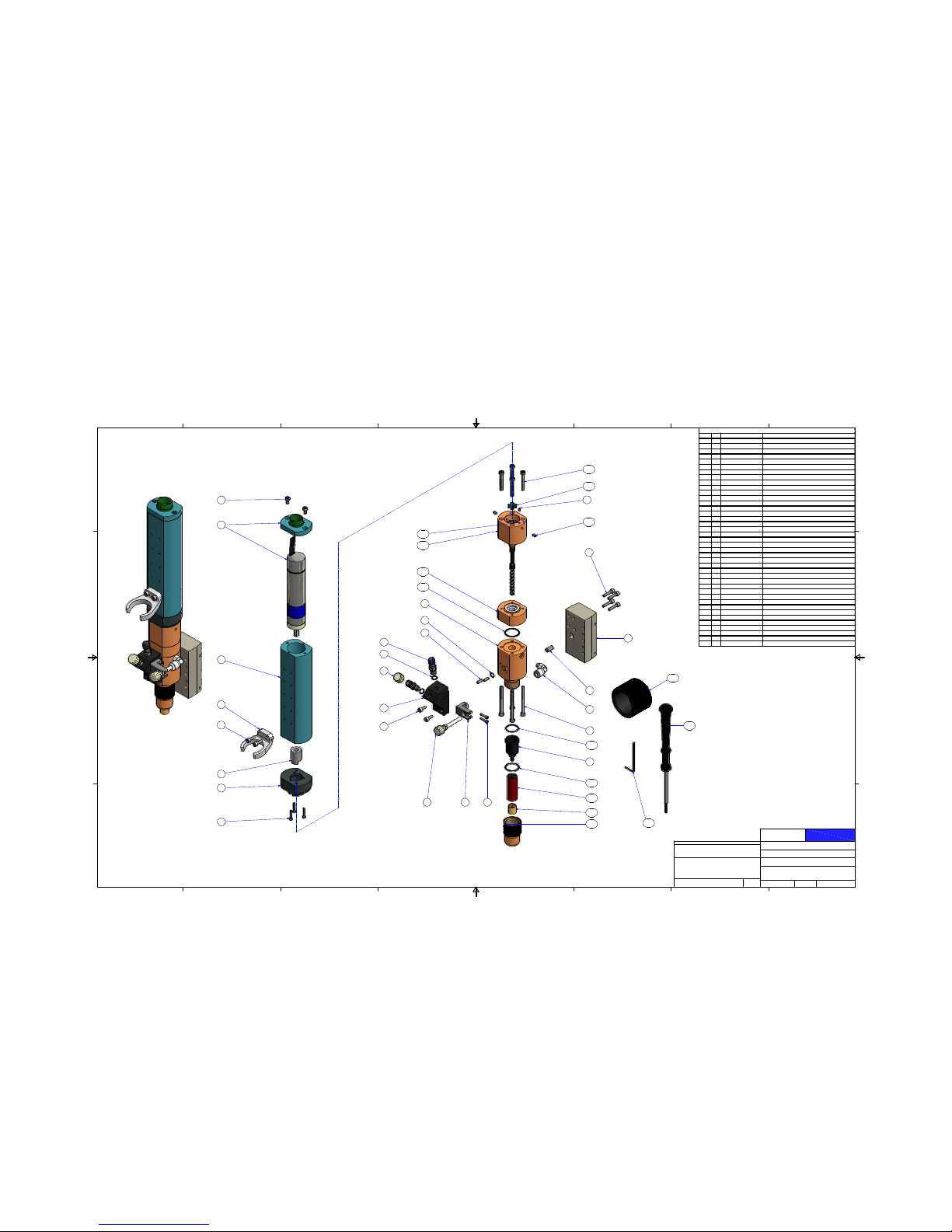
GPD Global
©
PCD4H - 22293227-0003
2/20/19 PCD Pump User Guide 49
PCD4H - 22293227-0003
Parts List
DESCRIPTION
PART NUMBER
QTY
ITEM
ELBOW_MALE_M5X4MM TUBE10/2017101
ADAPTER, THD, LUER, FEMALE, SST,1/4-3210/3171202
LUER CAP FITTING MALE LOCKING10/4836103
ORING,VITON_5mmID X 1mmW10/4912304
PURGE TUBE ASSY PCD VALVES
22110485105
COUPLER,6MM
22203421106
VALVE SECTION_PCD4H22203443107
END SECTION_PCD4H_W/6% TAPER22203447108
CLIP_PURGE VENT_PCD4H22203453109
SYRINGE TUBE/VENT BLOCK, PCD4H22203454110
SYRINGE SUPPORT_PCD 450_SNAP STYLE22203524111
BODY_AUGER_IN LINE CONNECTOR
22203730112
BODY ADAPTER_MICRO MOTOR ADAPTER
22203738113
MALE ADAPTER_PCD4H_EXTENDED REACH22203762114
DEVICE_PUMP MOTOR_INLINE CONNECTOR22293301115
VALVE PCD4 250MM CABLE_VER222293311-0003116
BEARING HOUSING W/ROTOR SET CPL10/4820116-01
COUPLING STAR SHAPED10/4673
116-02
SEAL SET W/HOUSING10/4821
116-03
O-RING FKM 15MM DIA X 1.510/4682116-04
ALLEN SCREW M3 X 2510/4687416-05
STATOR CPL_PCD410/4675116-06
THREADED SLEEVE LUER-LOCK10/4804116- 07
UNION RING PCD410/4803116-08
O-RING_FKM_.547ID X .051W
2575-0004116- 09
O-RING_FKM_.632 ID X .047 SECTION
2575-0005116- 10
SET SCREW M3 X 510/4678216-11
ASSEMBLY AID HAND DRIVER10/4674116 -12
WRENCH_HEX-KEY_1.5MM_L SHAPEM2003116- 13
WRENCH_HEX-KEY_2.5MM W/HANDLE10/4772116-14
DOWEL PIN 2mm X 4mm
DAM02004117
DOWEL PIN 3mm X 8mm
DAM03008218
DOWEL PIN 5mm X 10mmDAM05010119
SCR.A.CP.SST.MET.M2X.4_10MM LGSACSM020040010220
SCR.A.CP.SST.MET.M2X.4_12MM LGSACSM020040012321
SCR.A.CP.SST.MET.M3X.5_6MM LGSACSM030050006222
SCR.A.CP.SST.MET.M3X.5_8MM LGSACSM030050008223
SCR.A.CP.SST.MET.M3X.5_10MM LGSACSM030050010
224
SCR.A.CP.SST.MET.M3X.5_14MM LGSACSM030050014
425
SCR.A.CP.SST.MET.M3X.5_40MM LGSACSM030050040426
1
1
2
2
3
3
4
4
5
5
6
6
7
7
8
8
A A
B B
C C
D D
DWG SIZE
DWG NO
SHEET
OF
DRAWN BY
DESCRIPTION
ASSEMBLY
FINISH
MATERIAL
TOLERANCES UNLESS OTHERWISE SPECIFIED
FRACTIONS B1/32
HEAT TREATMENT
X.XX B0.015
X.XXX
B
0.005
ANGULAR
B
0.5
`
RUNOUT B0.003 T.I.R.
METRIC
0.0 MM
B
0.4 MM
0.00 MM
B
0.1 MM
GPD
Global
PUMP_PCD4H_SLEEVED MOTOR_EXT REACH
22293227-0003
1 1
D
MW
11/21/2016
PCD4 PUMP
N/A
N/A
0 MM B1.0 MM
15
12
21
13
19
09
01
08
02
10
03
23
05
06
26
07
LAST REVISED 5/4/2017
14
25
22
24
11
ASSEMBLED
EXPLODED
N/A
04
16-05
16-02
17
16-11
16-01
16-01
16-03
16-10
04
18
20
16-09
16-04
16-06
16-07
16-08
2X
2X
3X
2X
2X
2X
2X
4X
2X
2X
2X
16-12
16-14
16-13
LOOSE PART
LOOSE PART
LOOSE PART
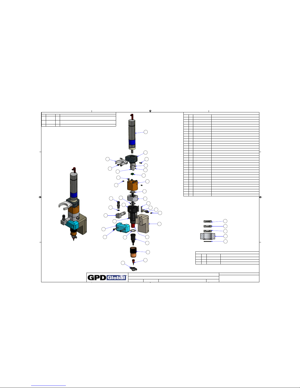
GPD Global
©
PCD4HB - 22293240
2/20/19 PCD Pump User Guide 50
PCD4HB - 22293240
Parts List
DESCRIPTIONPART NUMBERQTYITEM
ADAPTER, THD, LUER, FEMALE, SST,1/4-3210/3171
11
COUPLING STAR SHAPED10/467312
STATOR CPL_PCD410/4675
13
SET SCREW M3 X 510/467824
ALLEN SCREW M3 X 2010/468045
O-RING FKM 15MM DIA X 1.510/468226
WASHER,FLAT,TEFLON_.37 ODX.19 IDX.031 W10_347017
SCR.A.CP.SST.MET.M5X.8_6MM LGSACSM05008000618
ALLEN SCREW M3 X 2510/468749
UNION RING PCD4 (REPLACEMENT PN 22203610)10/4803
110
BEARING HOUSING W/ROTOR SET CPL10/4820111
SEAL SECT._PCD4_SST W/TEFLON LIP SEALS
22293781112
ORING,VITON_5mmID X 1mmW10/4912113
FEED RESERVOIR_PCD
22203375114
VALVE_PCD4 HALF CLAMP22203385115
MALE ADAPTER_PCD4
22203389116
COUPLER,6MM22203421117
MALE NEEDLE HUB_PCD4
22203628118
SYRINGE SUPPORT_PCD_VER2_ST RAIGHT22203523119
BODY ADAPTER_MICRO MOTOR ADAPTER22203605120
---
21
O-RING_FKM_.632 ID X .047 SECTION2575-0005122
PUMP HOUSING_PCD4_SST_SIDE PURGE22 203773123
MOTOR_SERVO_24VDC_W/ENCODER_DIFFER ENTIAL3500-0094124
DOWEL PIN 2mm X 4mmDAM02004125
DOWEL PIN 3mm X 8mmDAM03008226
DOWEL PIN 3mm X 20mm
DAM03020227
SCR.A.CP.SST.MET.M2X.4_12MM LGSACSM020040012328
CAP SCREW 3MM X 0.5 X 10MM LGSACSM030050010
229
CAP SCREW, SST, 3MM X 0.5 20MM LGSACSM030050020230
SET SCREW 3MMX0.5 X 5MM LG ALLOYTACAM0030050005
231
NUT_WING_MALE NEEDLE HUB_PCD22203635132
KIT,NEEDLE_TAPER TIPS 18G-30G S TYPE10/4783
133
Parts List
DESCRIPTIONPART NUMBERQTYITEM
PUMP HOUSING_PCD4_SST_SIDE PURGE2220378111
DISK_LIP SEAL_TEFLON_W/ORING
2575-008032
O-RING FKM 15MM DIA X 1.510/468213
1234
A A
B B
C C
D D
DRAWING NUMBER
SHEET OF
DRAWN BY:
DESCRIPTION:
ASSEMBLY:
PUMP_PCD4H-B_NEW MOTOR
22293240
1 2
IAH
12/3/2014
DATE:
REVISION HISTORY
REV DATE BY DESCRIPTION
A 10/12/2017 ALJ
ADDED 22203635, ADDED 10/4783, EXCHANGED 22203421 FOR
22203628 & 2650-0049 FOR 22203773
B 11/20/2017 ALJ
EXCHANGED 10/4685 FOR 10/3470 & 10/4684 FOR
SACSM050080006
C 2/28/2018 ALJ EXCHANGED 2575-0004 FOR 10/4682 & 10/4821 FOR 222937 81
24
26
20
29
19
28
25
17
2
4
9
22
12
1
13
14
6
27
7
8
31
16
23
5
15
30 3
6
18
10
11
LAST REVISED 6/1/2018
33
32
ITEM 12
22293781
1
2
2
2
3

GPD Global
©
PCD4HB legacy - 22293205
2/20/19 PCD Pump User Guide 51
PCD4HB legacy - 22293205
Parts List
DESCRIPTION
PART NUMBER
QTY
ITEM
COUPLING STAR SHAPED10/4673
11
STATOR CPL_PCD410/4675
12
SET SCREW M3 X 510/4678
23
ALLEN SCREW M3 X 2010/4680
44
O-RING FKM 15MM DIA X 1.510/4682
1
5
ALLEN SCREW M3 X 6
10/468416
WASHER A 3.210/4685
1
7
ALLEN SCREW M3 X 2510/4687
48
UNION RING PCD410/4803
19
THREADED SLEEVE LUER-LOCK10/4804
110
BEARING HOUSING W/ROTOR SET CPL10/4820
111
SEAL SET W/HOUSING10/4821
112
ASSY_SERVO MOTOR/TRANSMISSION
22141058113
VALVE_PCD4 HALF CLAMP
22203385114
MALE ADAPTER_PCD422203389115
COUPLER,6MM
22203421116
END SECTION_PCD4H_W/6% TAPER
22203447117
BODY ADAPTER_PCD4H MOTOR INTERFACE
22203449118
O-RING_FKM_.547ID X .051W
2575-0004119
O-RING_FKM_.632 ID X .047 SECTION
2575-0005120
DISPENSER HOUSING_PCD4_SIDE PURGE
2650-0049121
DOWEL PIN 3mm X 8mm
DAM03008222
DOWEL PIN 3mm X 20mm
DAM03020223
SCREW,BUTTON HEAD,3MMX.5 X 6MM,SSTSABSM030050006
424
CAP SCREW 3MM X 0.5 20MM LGSACSM030050020
225
SET SCREW 3MMX0.5 X 5MM LG ALLOYTACAM0030050005
226
1234
A A
B B
C C
D D
DRAWING NUMBER
SHEET OF
DRAWN BY:
DESCRIPTION:
ASSEMBLY:
PUMP_PCD4H-B
22293205
1 1
BLH
9/13/2013
DATE:
REVISION HISTORY
REV DATE BY DESCRIPTION
-- -
ORIGIN
A
LISSUE
4
11
21
12
7
6
25
14
23
15
9
17
2
10
26
1
16
18
22
8
24
13
20
5
3
19
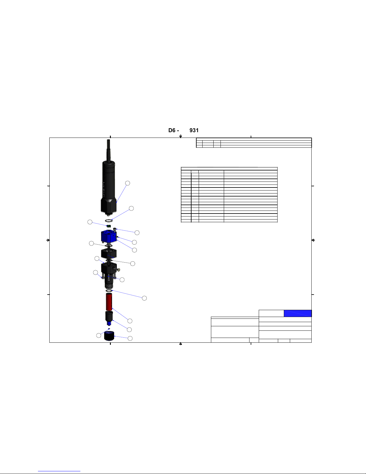
GPD Global
©
PCD6 - 22293160
2/20/19 PCD Pump User Guide 52
PCD6 - 22293160
Parts List
DESCRIPTION
PART NUMBER
QTY
ITEM
DRIVE UNIT_ PCD6
2220356411
COUPLING STAR SHAPED10/4673
12
O-RING NBR 17MM DIA X 1.2510/4691
13
BEARING HOUSING PCD6 W/ROTOR SET CPL
2650-010514
SEAL SET W/HOUSING PCD6
2650-011115
UNION RING PCD6
2650-010116
END PIECE PCD6 W/LUER-LOCK_OEM
2650-010217
DISPENSER HOUSING_PCD6
2650-010818
STATOR_PCD6_MOD
2220356119
ALLEN SCREW M4 X 25
2650-0107810
ALLEN SCREW M4 X 8
2650-0109112
SET SCREW M3 X 8 PCD6
2650-0106213
O-RING_NBR_16MM ID X 1.25
2575-0023114
O-RING_FKM_.110 ID X .028 SECTION
2575-0006115
O-RING_FKM_.547ID X .051W
2575-0004116
WASHER_NYLON_.150ID X .312OD X .015T
2825-0043118
O-RING FKM 16MM DIA X 1.2510/4679
121
1
1
2
2
3
3
4
4
A A
B B
C C
D D
DWG SIZE
DWG NO
SHEET
OF
DRAWN BY
DESCRIPTION
ASSEMBLY
FINISH
MATERIAL
TOLERANCES UNLESS OTHERWISE SPECIFIED
FRACTIONS B1/32
HEAT TREATMENT
X.XX B0.015
X.XXX
B0.005
ANGULAR
B0.5`
RUNOUT B0.003 T.I.R.
METRIC
0.0 MM
B0.4 MM
0.00 MM
B0.1 MM
GPD
Global
PUMP_PCD6_10" WIRE LENGTH_VER1 BLANK
22293160
2
3
C
BLH
3/7/2013
PCD6
NOTED
N/A
0 MM B 1.0 MM
REVISION HISTORY
REV DATE BY DESCRIPTION
-- -
ORIGINAL ISSUE
A6/27/16IHD
ADDED MISSING O-RINGS 10_4679, 2575-0004 AND 2825-0043 WAS 2650-0110
NONE
6
9
7
12
10
8
5
14
1
4
2
3
15
13
10
21
16
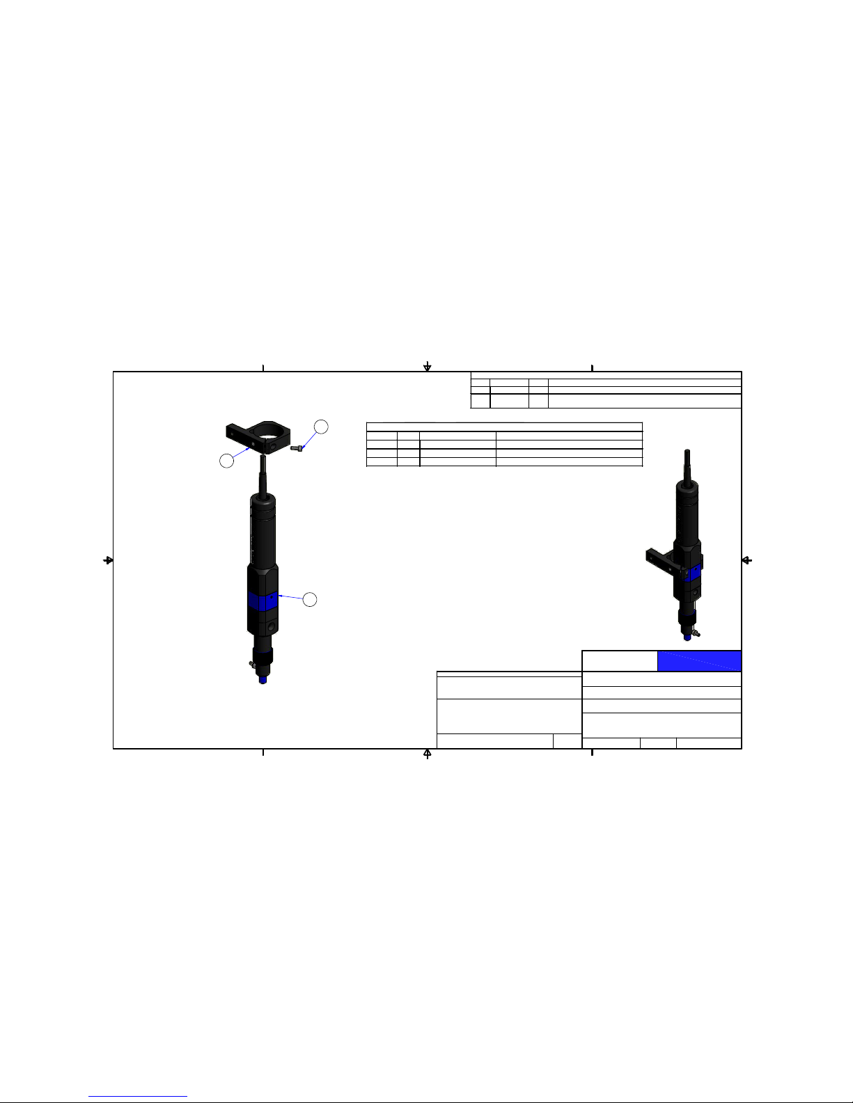
GPD Global
©
PCD6 - 22293161-001
2/20/19 PCD Pump User Guide 53
PCD6 - 22293161-001
Parts List
DESCRIPTION
PART NUMBER
QTY
ITEM
MOUNTING DISPENSE_TABBED_PCD 6
2230305311
PUMP_PCD6_10" WIRE LENGTH_VER1 BLANK2229316012
CAP SCREW 4MM X 0.7 - 10MM LGSACAM040070010
13
1
1
2
2
3
3
4
4
A A
B B
DWG SIZE
DWG NO
SHEET
OF
DRAWN BY
DESCRIPTION
ASSEMBLY
FINISH
MATERIAL
TOLERANCES UNLESS OTHERWISE SPECIFIED
FRACTIONS B 1/32
HEAT TREATMENT
X.XX B 0.015
X.XXX
B 0.005
ANGULAR
B 0.5`
RUNOUT B 0.003 T.I.R.
METRIC
0.0 MM
B 0.4 MM
0.00 MM
B 0.1 MM
GPD
Global
PUMP_PCD6_CONFIGURATION 001
22293161-001
1
3
B
BLH
3/7/2013
NOTED
N/A
0 MM B 1.0 MM
REVISION HISTORY
REV DATE BY DESCRIPTION
-- -
ORIGINAL ISSUE
A 6/27/16 IHD
ADDED MISSING O-RINGS 10_4679, 2575-0004 AND
2825-0043 W
A
S 2650-0110
1
NONE
2
3

GPD Global
©
PCD6HB - 22293161-003
2/20/19 PCD Pump User Guide 54
PCD6HB - 22293161-003
Parts List
DESCRIPTION
PART NUMBER
QTY
ITEM
ELBOW_MALE_M5X4MM TUBE10/2017
11
COUPLING STAR SHAPED10/4673
12
PURGE TUBE ASSY PCD VALVES
2211049513
COUPLER,6MM
2220342114
ADAPTER MOUNT_PCD3 VER2
2220343015
STATOR_PCD6_MOD
2220356116
DISPENSER HOUSING_PCD6_ALUMINUM
2220363317
BODY ADAPTER_MICRO MOTOR ADAPTER
2220363418
MALE ADAPTER_PCD6_NIPPLE
2220364819
O-RING_FKM_.547ID X .051W
2575-0004110
O-RING_FKM_.632 ID X .047 SECTION
2575-0005111
O-RING_NBR_16MM ID X 1.25
2575-0023112
UNION RING PCD6
2650-0101113
END PIECE PCD6 W/LUER-LOCK_OEM
2650-0102114
BEARING HOUSING PCD6 W/ROTOR SET CPL
2650-0105115
SET SCREW M3 X 8 PCD6
2650-0106216
ALLEN SCREW M4 X 25
2650-0107417
SEAL SET W/HOUSING PCD6
2650-0111118
MOTOR_GEAR_24VDC_W/ENCODER_DIFFERENTIAL
3500-0094119
DOWEL PIN 2mm X 4mm
DAM02004120
DOWEL PIN 5mm X 8mm
DAM05008121
CAP SCREW 3MM X 0.5 - 6MM LGSACANM030050006
422
SCR.A.CP.SST.MET.M2X.4_12MM LGSACSM020040012
323
ALLEN SCREW M4 X 40SACSM040070040
4
24
SCREW,FLATHEAD,4MM X 18LG ALLOYSAFANM040070018125
SET SCREW 3MMX.5 X 3MM LG SSTTACSM030050003126
O-RING_FKM_.110 ID X .028 SECTION2575-0006127
1
1
2
2
3
3
4
4
A A
B B
C C
D D
DRAWING NUMBER
SHEET OF
DRAWN BY:
DESCRIPTION:
ASSEMBLY:
PUMP_PCD6HB_CONFIG #3
22293161-003
1 2
IAH
3/6/2015
DATE:
REVISION HISTORY
REV DATE BY DESCRIPTION
-- -
ORIGINAL ISSUE
A6/27/16 I HD
ADDED 2575-0006
19
8
20
4
26
17
2
23
16
15
18
7
6
14
13
10
11
12
9
25
22
5
21
24
27

GPD Global
©
PCD7H - 22293306-003
2/20/19 PCD Pump User Guide 55
PCD7H - 22293306-003
Parts List
DESCRIPTIONPART NUMBERQTYITEM
MOTOR_GEAR_24VDC_W/ENCODER - 15:1
3500-010811
BODY ADAPTER_MICRO MOTOR ADAPTER2220363412
DOWEL PIN 2mm X 4mm
DAM0200413
COUPLER,6MM2220342114
SET SCREW 3MMX.5 X 3MM LG SSTTACSM03005000315
ALLEN SCREW M4 X 252650-010746
ADAPTER MOUNT_PCD3 VER22220343017
CAP SCREW 3MM X 0.5 - 6MM LGSACANM030050006
4
8
SCREW,FLATHEAD,4MM X 18LG ALLOYS AFANM04007001819
MALE ADAPTER_PCD6_NI PPLE
22203648110
DOWEL PIN 5mm X 8mmDAM05008111
ELBOW_MALE_M5X4MM TUBE10/2017
112
PURGE TUBE ASSY PCD VALVES22110495113
UNION RING PCD6
2650-0101114
END PIECE PCD6 W/LUER-LOCK_OEM265 0-0102115
END SECTION_PCD6
2650-0112115.1
THREADED SLEEVE LUER-LOCK10/46 90115.2
O-RING_FKM_.110 ID X .028 SECTION
2575-0006115.3
STATOR CPL_PCD62650-0373116
O-RING_NBR_16MM ID X 1.252575-0023117
ALLEN SCREW M4 X 40SACSM040070040418
DISPENSER HOUSING_PCD6_ALUMINUM22203633119
O-RING_FKM_.632 ID X .047 SECTION2575-0005120
SEAL SET W/HOUSING PCD62650-0111121
O-RING_FKM_.547ID X .051W2575-0004122
BEARING HOUSING PCD6 W/ROTOR SET CPL2650-0105123
SET SCREW M3 X 8 PCD6
2650-0106224
COUPLING STAR SHAPED10/4673125
SCR.A.CP.SST.MET.M2X.4_12MM LGSACSM020040012
326
1234
A A
B B
C C
D D
DWG SIZE
DWG NO
SHEET
OF
DRAWN BY
DESCRIPTION
ASSEMBLY
FINISH
MATERIAL
TOLERANCES UNLESS OTHERWISE SPECIFIE D
FRACTIONS B1/32
HEAT TREATMENT
X.XX B0.015
X.XXX
B
0.005
ANGULAR
B
0.5
`
RUNOUT B0.003 T.I.R.
METRIC
0.0 MM
B
0.4 MM
0.00 MM
B
0.1 MM
PUMP_PCD6HB_CONFIG #3
22293306-0003
1 2
C
IAH
2/12/2019
-
-
0 MM B1.0 MM
1
2
3
4
5
6
25
26
24
23
21
19
16
15.1
14
22
20
17
10
9
8
7
11
18
15.2
15.3
LAST REVISED 2/18/2019
12
13
EXPLODED
ASSEMBLED

GPD Global
©
Level Detect, DS Series - 22110521
2/20/19 PCD Pump User Guide 56
Level Detect, DS Series - 22110521
Parts List
DESCRIPTIONPART NUMBERQTYITEM
2220338211
2220342712
2220361513
5500-005714
DAM0300815
S0061
26
SABSM030050008
2
7
SACSM03005000428
SACSM030050008
39
SAFANM030050012
210
SENSOR MOUNT
MOUNT_LEVEL_PCD_VER2
MOUNT_VERT ADJUST_PCD LEVEL DETECT
SENSOR CAPACITIVE
DOWEL PIN 3mm X 8mm
EXTENSION SPRING
SCREW,BUTTON HEAD,3MMX.5 X 8MM,SST
CAP SCREW 3MM X .05 4MM LG
CAP SCREW 3MM X .05 8MM LG, SST
SCREW,FLATHEAD,3MM X 12LG ALLOY
WASHER,FLAT,REGULAR,ALLOY,M3
WFRBAMM3111
1
2
3
4
A A
B B
DWG SIZE
DWG NO
SHEET
OF
DRAWN BY
DESCRIPTION
ASSEMBLY
FINISH
MATERIAL
TOLERANCES UNLESS OTHERWISE SPECIFIED
FRACTIONS B1/32
HEAT TREATMENT
X.XX B0.015
X.XXX
B
0.005
ANGULAR
B
0.5
`
RUNOUT B0.003 T.I.R.
METRIC
0.0 MM
B
0.4 MM
0.00 MM
B
0.1 MM
GPD
Global
LEVEL DETECT_PCD_VER2_CAPACITANCE
22110521
1
1
B
IAH
12/5/2013
PCD
0 MM B1.0 MM
REVISION HISTORY
REV DATE BY DESCRIPTION
-
12/03/2010 ARM O RIGINAL ISSUE
A
1/20/14 IAH
22203382 WAS 22203428, 22203615 WAS 22203429
ALL FASTENERS ARE PLATED ALLOY
OR STAINLESS STEEL
7
6
9
1
10
4
8
2
11
9
5
3

GPD Global
©
Level Detect, MAX Series - 22293101
2/20/19 PCD Pump User Guide 57
Level Detect, MAX Series - 22293101
Parts List
DESCRIPTIONPART NUMBERQTYITEM
2220338211
2220342712
2220361513
5500-005714
DAM0300815
S0061
26
SABSM030050008
2
7
SACSM03005000628
SACSM030050008
39
SAFANM030050012
210
SENSOR MOUNT
MOUNT_LEVEL_PCD_VER2
MOUNT_VERT ADJUST_PCD LEVEL DETECT
SENSOR CAPACITIVE
DOWEL PIN 3mm X 8mm
EXTENSION SPRING
SCREW,BUTTON HEAD,3MMX.5 X 8MM,SST
CAP SCREW 3MM X .05 6MM LG, SST
CAP SCREW 3MM X .05 8MM LG, SST
SCREW,FLATHEAD,3MM X 12LG ALLOY
WASHER,FLAT,REGULAR,ALLOY,M3
WFRBAMM3111
1
1
2
2
3
3
4
4
A A
B B
DWG SIZE
DWG NO
SHEET
OF
DRAWN BY
DESCRIPTION
ASSEMBLY
FINISH
MATERIAL
TOLERANCES UNLESS OTHERWISE SPECIFIED
FRACTIONS B1/32
HEAT TREATMENT
X.XX B0.015
X.XXX
B
0.005
ANGULAR
B
0.5
`
RUNOUT B0.003 T.I.R.
METRIC
0.0 MM
B
0.4 MM
0.00 MM
B
0.1 MM
GPD
Global
LEVEL DETECT_PCD_VER2_CAPACITAN
22293101
1
1
B
ARM
12/3/2010
22293100
0 MM B1.0 MM
REVISION HISTORY
REV DATE BY DESCRIPTION
-
12/03/2010 ARM O RIGINAL ISSUE
A
1/20/14 IAH
22203382 WAS 22203428, 22203615 WAS 22203429
ALL FASTENERS ARE PLATED ALLOY
OR STAINLESS STEEL
9
11
5
2
8
10
4
1
9
6
3
7

GPD Global
©
Clamp Mount Hole Patterns & Groove - 22212002
2/20/19 PCD Pump User Guide 58
Clamp Mount Hole Patterns & Groove - 22212002
1
2
3
4
DWG SIZE
DWG NO
SHEET
OF
DRAWN BY
DESCRIPTION
ASSEMBLY
FINISH
MATERIAL
TOLERANCES UNLESS OTHERWISE SPECIFIED
FRACTIONS B 1/32
HEAT TREATMENT
X.XX B 0.015
X.XXX
B 0.005
ANGULAR
B 0.5`
RUNOUT B 0.003 T.I.R.
METRIC
0.0 MM
B 0.4 MM
0.00 MM
B 0.1 MM
GPD
Global
MOUNTING INFORMATION_PCD_CLAMPS
22212002
1
2
B
IAH
3/14/2014
PCD
-
-
0 MM B 1.0 MM
REVISION HISTOR
Y
REV DATE BY DESCRIPTION
-- -
ORIGINAL ISSUE
NOTES UNLESS OTHERWISE SPECIFIED:
1. EDGE BREAK ALL CORNERS, EDGES AND HOLES:
0.10/0.40 FOR MATERIAL >= 2.50 THICK
5%/15% OF THICKNESS FOR MATERIAL < 2.50 THICK
2. 0.40 MAXIMUM FILLET
3. 64 MACHINE FINISH OR BETTER
4. ALL DIMENSIONS ARE PRE-PLATE (IF APPLIED)
5. PLATING THICKNESS IS PER SIDE (IF APPLIED)
6. REMOVE RAW STOCK LETTERING, LINEAR GRAIN, OR
MATERIAL REMOVAL
16.10
-
0.00
0.05
+
0.634
-
.000
.002
+
in
1.00
[0.039 in]
55.00
[2.165 in]
71.00
[2.795 in]
2X M4x0.7 - 6H THRU
(FOR PCD 3 AND PCD4)
2X M5x0.8 - 6H THRU
(FOR PCD 6)
8.05
[0.317 in]
FOR USE WITH PCD MOUNTING
BRACKETS 22303041, 22303039,
& 22303053 (SEE SHEET 2)
27.50
[1.083 in]
35.50
[1.398 in]
CENTERLINE OF PUMP
LEFT OR RIGHT MOUNTING

GPD Global
©
Clamp Mount Dimensions - 22212002
2/20/19 PCD Pump User Guide 59
Clamp Mount Dimensions - 22212002
1
2
3
4
A A
B B
DWG SIZE
DWG NO
SHEET
OF
DRAWN BY
DESCRIPTION
ASSEMBLY
FINISH
MATERIAL
TOLERANCES UNLESS OTHERWISE SPECIFIED
FRACTIONS B 1/32
HEAT TREATMENT
X.XX B 0.015
X.XXX
B 0.005
ANGULAR
B 0.5`
RUNOUT B 0.003 T.I.R.
METRIC
0.0 MM
B 0.4 MM
0.00 MM
B 0.1 MM
GPD
Global
MOUNTING INFORMATION_PCD_CLAMPS
22212002
2
2
B
IAH
3/14/2014
PCD
-
-
0 MM B 1.0 MM
45.00
[1.772 in]
55.00
[2.165 in]
15.00
[0.591 in]
25.00
[0.984 in]
35.00
[1.378 in]
22303039
Models: PCD4H, PCD4L, PCD4
22303041
Models: PCD3H, PCD3L, PCD3
55.00
[2.165 in]
35.00
[1.378 in]
15.00
[0.591 in]
25.00
[0.984 in]
45.00
[1.772 in]
73.00
[2.874 in]
49.00
[1.929 in]
22303053
Model: PCD6
28.00
[1.102 in]
52.00
[2.047 in]
25.00
[0.984 in]
7.50
[0.295 in]
35.00
[1.378 in]
8.00
[0.315 in]
M8x1.25 - 6H
P 4.50 THRU
[
P 0.177 in THRU]
16.00
[0.630 in]
7.50
[0.295 in]
35.00
[1.378 in]
8.00
[0.315 in]
16.00
[0.630 in]
P 4.50 THRU
[
P 0.177 in THRU]
M8x1.25 - 6H
16.00
[0.630 in]
M8x1.25 - 6H
M8x1.25 HOLES FOR ALTERNATIVE MOUNTING OPTION
8.00
[0.315 in]
13.50
[0.531 in]
49.00
[1.929 in]
P 5.50 THRU
[
P 0.217 in THRU]
LAST MODIFIED 03/01/2017

GPD Global
©
Taper-Lock Mounting Detail - 22110291
2/20/19 PCD Pump User Guide 60
Taper-Lock Mounting Detail - 22110291
1
1
2
2
3
3
4
4
A A
B B
C C
D D
DWG SIZE
DWG NO
SHEET
OF
DRAWN BY
DESCRIPTION
ASSEMBLY
FINISH
MATERIAL
TOLERANCES UNLESS OTHERWISE SPECIFIED
FRACTIONS B1/32
HEAT TREATMENT
X.XX B0.015
X.XXX
B
0.005
ANGULAR
B
0.5
`
RUNOUT B0.003 T.I.R.
METRIC
0.0 MM
B
0.4 MM
0.00 MM
B
0.1 MM
GPD
Global
TAPER LOCK QUICK RELEASE
22110291
3 3
C
SO
10/30/2007
DS/MM
NA
NA
51.82 [2.040 in]
148.27 [5.838 in]
88.90 [3.500 in]
50.80 [2.000 in]
50.80 [2.000 in]
58.93 [2.320 in]
14.99 [0.590 in]
27.99 [1.102 in]
11.40 [0.449 in]
40.59 [1.598 in]
25.40 [1.000 in]
(25.40 [1.000 in])
(40.59 [1.598 in])
10.11 [0.398 in]
(88.90 [3.500 in])
(51.82 [2.040 in])
6.3 [0.25 in]
P
6.35 [0.250 in]
X
4X Ø3.18 [0.125 in] THRU
Z
19.30 [0.760 in]
 Loading...