


Operating Guide
In addition to installation, set up, and operating
specifications details.
Bills of Material
Includes an illustrated bill of material with associated
part numbers for each CF-9 subassembly.
Die Catalog
Catalog of dies precisely manufactured by GPD Global®
variety of component shapes.
Set Up Form
Fill out this Set Up form and then use it as a guide for
consistent results for each component part number.
Documentation Package
for CF-9 Taped Radial Component Lead Former
PN 901-1-01
CONTENTS of CF-9 Documentation Package
procedures, this guide includes electrical schematics and
maintenance, troubleshooting, spare parts, and
to accurately form Radial components into a wide
611 Hollingsworth Street
Grand Junction, CO, USA 81505
tel: +1.970.245-0408
fax: +1.970.245-9674
request@gpd-global.com
www.gpd-global.com

CF-9
Radial Lead Forming Machine
User's Guide
Version 2.1
June 4, 2014
Prepared by
GPD Global
®
Documentation Department
©
Copyright
2014 GPD Global
All Rights Reserved
GPD Global
611 Hollingsworth Street
Grand Junction, CO 81505
(970) 245-0408
CF-9 User's Guide CF-9 Radial Lead Forming Machine
Part No. 901-1-07 Serial No.
®
®


CF-9 User's Guide
Warranty
GPD Global (GPD) warrants that this product will be free from defects in material and
workmanship for a period of one (1) year from the date of original purchase. GPD will repair, or
at its option, replace this GPD product during the war ranty period at no charge, provided it is
returned (shipping-postage paid) to the GPD, Colorado service facility.
The one year warranty does not cover nor mal wear and tear to the cutting and forming tooling,
since life usually depends on use.
This warranty does not apply if the GPD product has been damaged by accident, abuse, misuse,
or misapplication, has been modified without the wri tten permission of GPD, or if any GPD serial
number has been removed or defaced.
GPD IS NOT RESPONSIBLE FOR INCIDENTAL OR CONSEQUENTIAL DAMAGES
RESULTING FROM THE BREACH OF ANY EXPRESS OR IMPLIED WARRANTY INCLUDING
ANY COSTS OR DAMAGE TO PROPERTY, AND, TO THE EXTENT PERMITTED BY LAW,
DAMAGES FOR PERSONAL INJURY. THIS WARRANTY IS IN LIEU OF ALL OTHER
WARRANTIES. ANY IMPLIED WARRANTIES, INCLUDING IMPLIED WARRANTIES OF
MERCHANTABILITY AND FITNESS FOR A PARTICULAR PURPOSE, ARE LIMITED IN
DURATION TO ONE (1) YEAR FROM THE DATE OF RECEIPT OF THIS PRODUCT. GPD'S
LIABILITY ON ANY CLAIM OF ANY KIND INCLUDING NEGLIGENCE, FOR LOSS OR
DAMAGE ARISING OUT OF, CONNECTED WITH OR RESULTING FROM THE BREACH OF
ANY EXPRESS OR IMPLIED WARRANTY OR THE DELIVERY, REPAIR, OR USE OF ANY
GPD PRODUCT SHALL IN NO CASE EXCEED THE PRICE ALLOCABLE TO THE GPD
PRODUCT WHICH GIVES RISE TO THE CLAIM.
Specifications, descripti ons, and all information contained in this manual are subject to change
and/or correction without notice.
Although reasonable care has been exerci sed in the preparation of this manual to make it
complete and accurate, this manual does not purport to cover all conceivable problems or
applications pertaining t o this machine.
09/30/92 GPD Global i
CF-9 User's Guide
Safety Instructions
Symbol samples and definit ions for the DANGER, WARNING, CAUTION, IMPORTANT and
NOTE safety notices used in this document are as follows:
** D A N G E R **
Danger notices are used in this document t o emphasize life threateni ng or potentially
harmful situations.
W A R N I N G
Warning notices are used in this document to emphasize chance of injury, harm to l ife or
limb due largely to something beyond one's control.
C A U T I O N
Caution notices are used in this document to alert one to avoid danger or harm and where
equipment might be damaged if care is not taken.
I M P O R T A N T
Important notices are used i n this document to call attention to imperative infor m ation.
NOTE
Note is used in this document to call attention to information that is especially significant in
understanding and operating the equipment.
ii GPD Global 09/30/92

CF-9 User's Guide
Table of Contents
Introduction ................................................................ 1
Function ................................................................... 3
Theory of Operation .......................................................... 4
Machine Part Identification ..................................................... 5
Principal Parts ........................................................ 5
Adjustment Parts ...................................................... 6
Control Panel ......................................................... 7
Die Block Assembly.................................................... 8
Die Markings ......................................................... 9
Installation ................................................................. 11
Operating Instructions ........................................................ 13
Setup ............................................................... 13
Die Installation .................................................. 14
Station Adjustment............................................... 16
Component Alignment ............................................ 17
Load Components ..................................................... 18
Power On............................................................ 18
Process Components ................................................... 19
Power Off............................................................ 19
Preventive Maintenance ...................................................... 21
Troubleshooting ............................................................. 23
Slide Travel .......................................................... 24
Slide Clearance ....................................................... 25
Specifications............................................................... 29
Suggested Spare Parts ....................................................... 31
Appendices ................................................................ 33
Appendix A - Die Informati on ............................................. 35
Appendix B - Common CF-9 Lead Forms ................................... 37
Appendix C - CF-9 Accessories ........................................... 39
Appendix D - Electrical Schematic & Assembly Drawing ....................... 43
Index ...................................................................... 45
Reference CF-9 Component Forming Di e Catalog
09/30/92 GPD Global iii

CF-9 User's Guide
Table of Figures
Figure 1 Principal Parts .................................................. 5
Figure 2 Adjustment Parts ................................................ 6
Figure 3 Control Panel .................................................... 7
Figure 4 Die Block Assembly, Station 1...................................... 8
Figure 5 Die Forming Style Series ......................................... 9
Figure 6 Die & Station Markings ........................................... 9
Figure 7 CF-9 Installation................................................. 11
Figure 8 Die Mounting Surface & Die Block Sli de .............................. 14
Figure 9 Die Alignment & Knife Clearance ................................... 14
Figure 10 Ejector Brackets................................................. 15
Figure 11 Adjust Large Ejector Bracket ....................................... 15
Figure 12 Adjust Small Ejector Bracket ....................................... 15
Figure 13 Station Position Adjustment........................................ 16
Figure 14 Die Block Assembly Adjusting Bolts ................................. 16
Figure 15 Component Position Relative to Tape Hole ........................... 17
Figure 16 Align & Load Components ......................................... 18
Figure 17 Die Block Assembly Lubrication .................................... 21
Figure 18 Die Block Assembly Maintenance ................................... 21
Figure 19 Die Block Assembly Slide Travel.................................... 24
Figure 20 Die Block Assembly Slide Clearance................................. 25
Figure 21 Die Block Assembly Lubrication .................................... 26
Figure 22 GPD's CF-9 Taping Specification Requirements ....................... 30
Figure 23 Forming Style Series ............................................. 35
Figure 24 Examples of Die Numbers......................................... 35
Figure 25 Examples of Die Number Location .................................. 35
Figure 26 Electronic Component Counter Installation ............................ 40
Table of Charts
Chart 1 Preventive Mai ntenance Schedule .................................. 21
Chart 2 Troubleshooting Guide ........................................... 23
iv GPD Global 09/30/92

CF-9 User's Guide
Introduction
This document is intended for use by those who install, operat e and maintain GPD's CF-9 Radial
Lead Forming Machine (GPD Part# CF9. BASE.120 or CF9.BASE.230).
CF-9 Radial Lead Forming Machine
GPD's self-contained CF-9 Radial Lead For ming Machine has become the industry standard for
versatility, accuracy , repeatability, and ease of setup and change over. The CF-9 forms and cuts
to length a wide variety of two- and three-leaded taped radial components such as TO-92's,
capacitors, transisto rs, and LED's. It processes both st andard and special forms precisely and
repeatedly.
Two die stations with st andard micrometer scale indicators adjust independently. Performing
adjustments with the micrometer scales enables quick setup of proper forming and/or cutting
settings.
As the first component moves through the system, i t is presented to two die stations. The first
die station is generally used to form components, and the second to cut components from the
tape. Depending on the components being processed and the desired component lead form,
the second station may be used to both cut and form, just cut, or be excluded in order to l eave
components on tape.
The indexing system, the heart of the CF-9, drives the studded transfer belt. The studs, or pins,
on the belt pick up the tape holes and index exactly
The CF-9 is ruggedly constructed of heavy duty parts and sealed ball bearing shaft assemblies
for low maintenance. All of the machine's parts are precisely made and treated to pr event
corrosion, enhance appearance, or facilitate proper function.
The tape roller guide includes studded pr otrusions to hold the component tape sol idly in place —
the tape cannot run off the driv e belt mechanism. Waste tape feeds down a tape exit chute and
out to the side of the machine for easy disposal.
The CF-9's capabilities expand with its Loose/Bulk Component Feeder and Automatic Taped
Component Re-reeler accessories by combining the functions of several machines into one.
Additional accessories such as the Elect ronic Component Counter, Component Detect ion
System, Lazy Susan, Work Station, and Footswit ch are also available to help increase your
production and profit.
1/2" (12.70 mm) every time.
09/30/92 GPD Global 1

CF-9 User's Guide
CF-9 Lead Forming Dies
The CF-9 offers unique versatility through the use of a large selection of dies. The CF-9
operates on a system of di es and die blocks. Each die combination is designed t o form a
specific lead configuration. Numerous standard and special CF-9 Lead Forming Die sets are
available to provi de a variety of component forms and lead configurations. Many different die
sets for various transi stor hole patterns are also available.
A minimal amount of preparation time is required to reset the machine for processing different
component sizes. Dies are easi ly replaced within minutes.
GPD's CF-9 dies are precisely manufactured using a unique die const ruction process. Most
dies are built with a sectional, laminated construction method for exceptional wearing ability.
Before lamination, all dies are buffed and polished to exacting smoothness, particularly in the
actual forming and cutting ar eas.
2 GPD Global 09/30/92

CF-9 User's Guide
Function
CF-9 Radial Lead Forming Machine
The CF-9 performs the following functions:
• Forms and cuts up to 25,000 radial components per hour with a variable speed motor.
• Produces a variety of lead forms.
• Accommodates components with a wi de range of lead diameters.
• Handles a diversity of hole-to-hole spacings.
• Controls accuracy and repeatability through the use of a solid gear train, cam, and cam
follower indexing system.
Most cutting and formi ng needs are covered with the standard dies we offer. Sever al of the
most common component forms the CF-9 produces are illustrated in the Common CF-9 Lead
Forms appendix.
CF-9 Lead Forming Dies
CF-9 Lead Forming Die sets are available to perform the following functions:
• Produce both common and special configurations. GPD is pleased to design custom dies
for you. If you have unusual requirements, your GPD representative w ill be happy to assist
you with any custom die orders.
• Form two-leaded components with up to .400" (10.16 mm) center-to-center dimensions.
• Form three-leaded TO-92 transist ors.
• Offer unique versatility through the use of a large selection of different dies to form a wide
variety of component shapes.
NOTE
All CF-9 dies will also work on the GPD CF-10 Loose/Bulk Component Lead Former.
09/30/92 GPD Global 3

CF-9 User's Guide
Theory of Operation
The CF-9 performs the following steps during a cycle:
1. Feeds taped radial components from the reel holder through a pair of tape r oller guides
into the feeding mechanism and the formi ng and cutting die stations.
2. Forms the component in the first die station.
3. Indexes the formed component to the second die station while simul taneously indexi ng the
next component into the first die station.
4. Cuts the formed component from the tape i n the second die station, drops the component
in the component bin, and disposes of the tape down a waste tape exit chute while
simultaneously forming the component at the first die station.
5. Initiates next cycle.
NOTE
Depending on the components being processed and the desired component lead form, die
Station 2 may be used t o both cut and form, just cut, or be excluded in order to leave
components on tape.
4 GPD Global 09/30/92
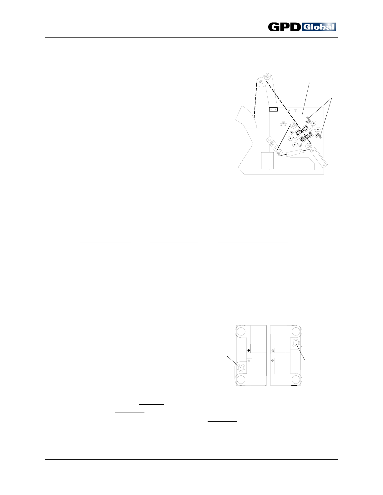
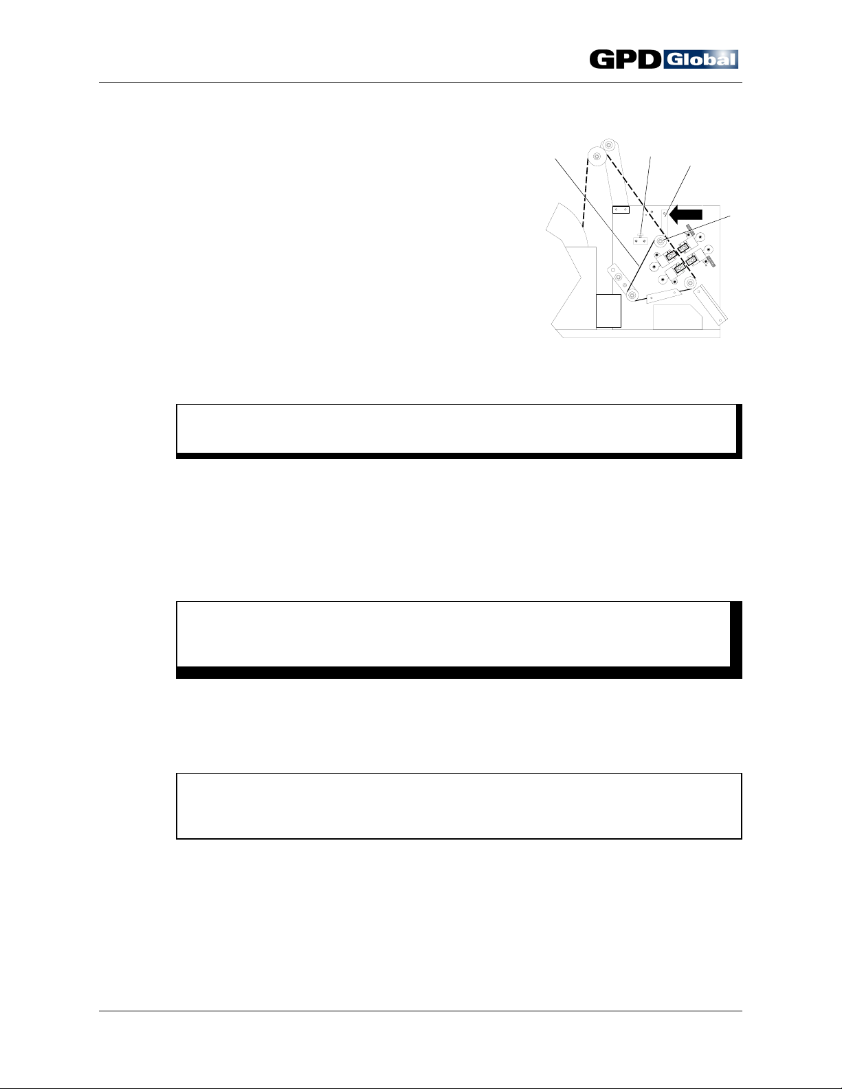
3
CF-9 User's Guide
Machine Part Identification
The CF-9's principal machine and die elements are identified and illustrated in this section.
Information for elements not defined elsewhere is also included here.
Principal Parts
4
1
2
5
6
7
8
9
Figure 1 Principal Parts
Item 1 Reel Holder Item 6 Die Block Assembly, St ation 1
Item 2 Component Reel / Ammo Pack Item 7 Die Block Assembly, St ation 2
Item 3 Tape Roller Guide Item 8 Component Bin
Item 4 Tape Guide Arm Item 9 Tape Exit Chute
Item 5 Taped Components
Die Stations
Station 1 is adjustable and normal ly used as a forming station. Station 2, also adjustable,
is normally used as a cutting station. More complicated forms may require Station 2 to
complete the forming function pr ior to cutting the component fr om the tape, or special
flattening blocks can be inserted if additional dimple alignment is required.
09/30/92 GPD Global 5
3
CF-9 User's Guide
Adjustment Parts
2
1
4
5
Figure 2 Adjustment Parts
Item 1 Belt Tension Release Bar Item 4 Component Tape Pressure Plate
Item 2 Transfer Belt Lever
Item 3 Safety Shield Lock Item 5 Drive Pulley
Hand Crank
Not shown. The hand crank port is locat ed in the lower left corner of machine's back
panel. By inserting the supplied Allen Key in this port, the operator can slowly operate the
CF-9 manually, moving all mechanisms during setup, adjustment, testing, or
troubleshooting to assure proper die and component positioning. The hand crank can be
used to move mechanisms in reverse onl y during setup and only when no components are
loaded.
Safety Shield
Not shown. The safety shi eld must be in place during machine operations. Machine
operations cease whenever the shield is opened.
(adjusts Transfer Belt timing)
6 GPD Global 09/30/92
Control Panel
CF-9 User's Guide
1
5
4
3
6
7
10
RUN
STOP
AUX.
8
9
RESET
CF9
Component
Former
2
1
0
Figure 3 Control Panel
Item 1 Speed Control Item 4 Fuse
Item 2 Power Switch
(RUN, STOP, AUX)
Item 5 Accessory Outlet
Item 3 Reset Button
2
3
4
5
Speed Control
The speed control regulates both the variable speed motor and power supply and enables
the machine to operate in a range fr om 0 to 25,000 cycles per hour . The operator has full
freedom to select whatev er speed is appropriate to the work being performed.
Reset Button
As a safety feature, power is not automatically restored by closing the safety shield. To
restore power, it is necessary to cl ose the shield and then push the reset butt on. Normal
operation can then be resumed.
09/30/92 GPD Global 7
CF-9 User's Guide
Die Block Assembly
1
2
3
4
5
4
2
9
6
T
1
10
7
B
1
8
11
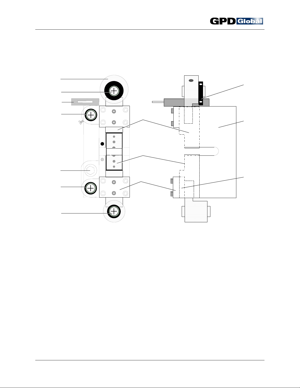
Figure 4 Die Block Assembly, Station 1
Item 1 Eccentric Crank Item 7 Die Mounting Area
Item 2 Crank Shaft Item 8 Cover Plate
Item 3 Micrometer Scale Indicator Item 9 Crank Adjuster
Item 4 Die Station Guide Shaft Item 10 Die Block
Item 5 Die Block Adjusting Bolt Item 11 Wear Plate
Item 6 Die Block Slide
Micrometer Scale Indicator
The micrometer scale indicator mount ed on each die station makes the lead cut length
adjustment operation quick, easy, and highly accurate to .0005" (0.0127 mm).
8 GPD Global 09/30/92
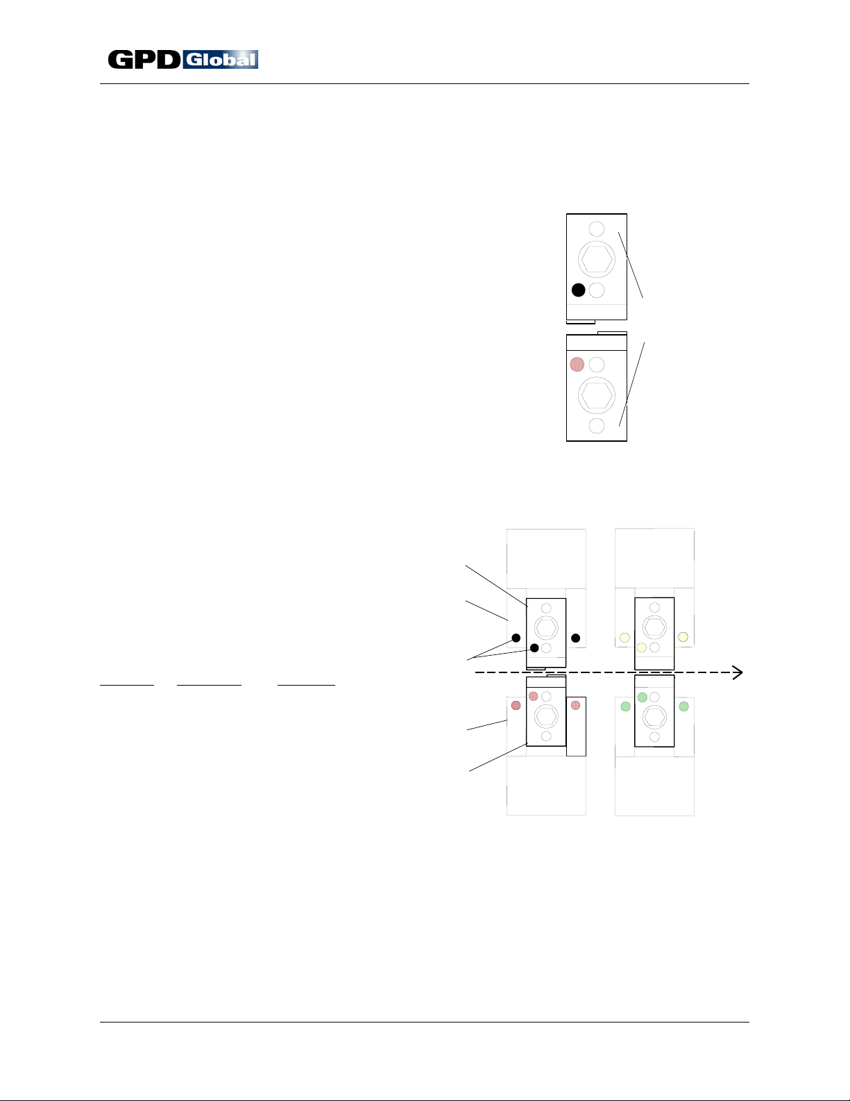
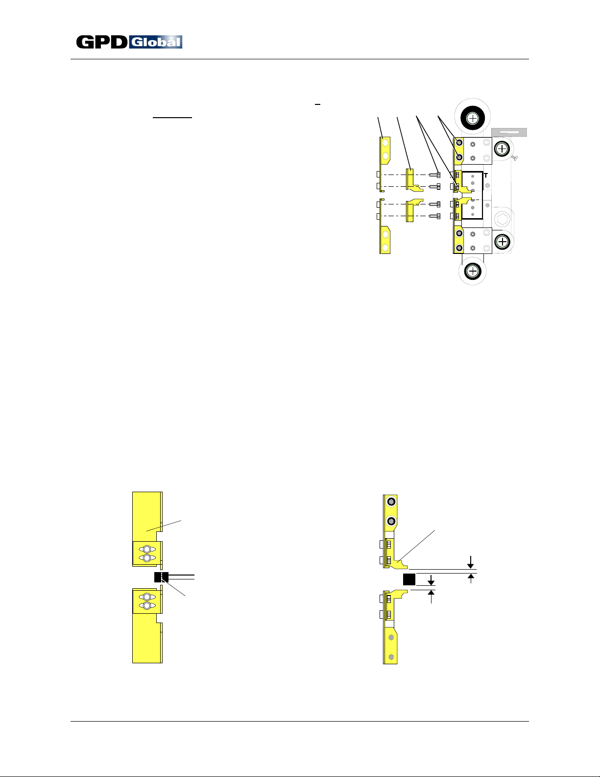
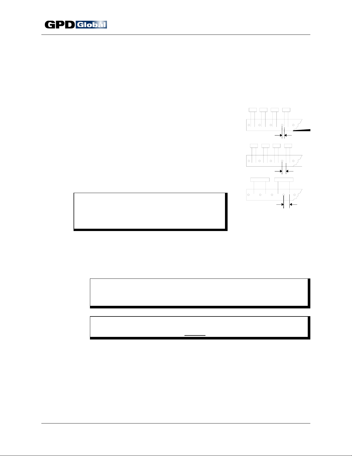
Die Markings
Dies and knives are paired and stamp mar ked with the following
symbols so each can be readily identified and installed in the
correct station posit ion:
• Forming Style Series Number
• Installation Marking
• Installation Color Dot
Forming Style Series
The forming style ser ies is stamped on its right hand side of
each die and knife (Figure 5). Refer t o the Die Information
appendix for specifics.
Installation Marking
Installation Color Dot
Characters are stamped on the left hand side of
each die half (Figure 6, Item 1) to indicate proper
die position in the formi ng and cutting stations.
Corresponding markings are stamped on each
station's stationary plate (Item 2). A color dot
(Item 3) associated with installation location is
also stamped on each die half and stationary
plate.
Marking
Color Dot Location
T1 Black Top die, Station 1
B1 Red Bottom die, Station 1
T2 Yellow Top die, Station 2
B2 Gr een Bottom die, Station 2
1
2
T
1
3
B
2
1
1
CF-9 User's Guide
T
2
1
Forming
Style Series
B 1
2
Figure 5
T
1
B 1 2 B 2 5
Die Forming Style Series
2
T
2
T
2
B
2
5
Tape
Figure 6 Die & Station Markings
09/30/92 GPD Global 9

CF-9 User's Guide
This page left blank (almost).
10 GPD Global 09/30/92
3
CF-9 User's Guide
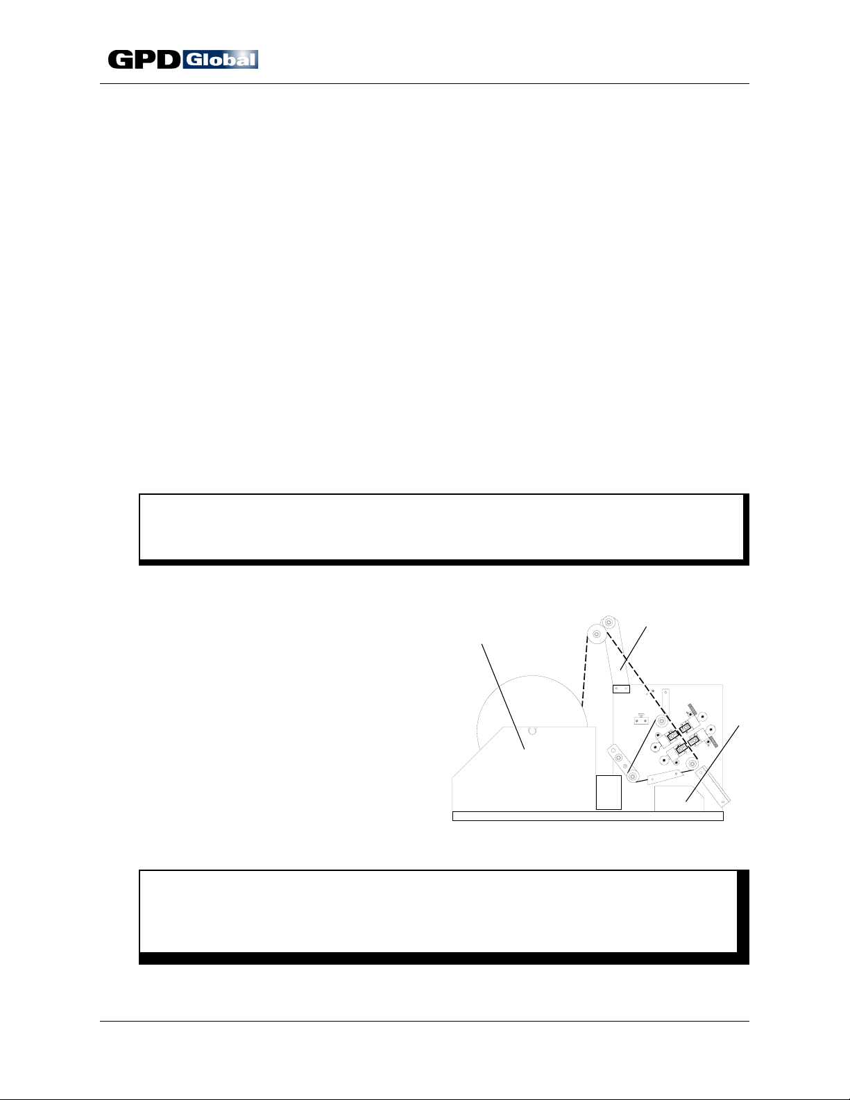
Installation
1. Carefully unpack and check your CF-9 for possible shi pping damage. If any obvi ous
damage is observed, contact GPD's ser vice department prior t o operating the machine.
2. Standard equipment included with the CF-9:
1 Standard Die Set 1 Reel / Ammo Pack Holder
1 Standard Knife Set 1 Operating Manual
1 Anti-static Shield and Bin Package 1 Set of Wrenches
1 LCD Micrometer Adjustment Package
3. Position the CF-9 on a level, stable working surface. I f usi ng the optional Lazy Susan or
Work Station, install CF-9 on these at this time.
4. Assemble reel holder and tape guide arm. Refer to Figure 7, Items 1 & 2 for pr oper
placement on the machine. The screws (1/ 4-20x1/2") for securing t he reel holder and tape
guide arm are located in the appropriate holes in the CF-9's main frame.
C A U T I O N
Never pull, push or lift machine by reel holder or tape guide arm - this could bend
them out of alignment and seriously affect machine performance.
5. Assemble safety shiel d with hinges and 10-32x3/8" screws attached to shield.
2
6. Position component bin (Item 3).
7. Install any accessory equipment to be used
during processing. Refer to CF-9
Accessories appendix.
8. Set speed control to zero (0) position.
9. Hook up electrical power per your local
electrical code and machine specifications.
Refer to Specifications.
1
Figure 7 CF-9 Installation
W A R N I N G
Make sure the power suppli ed is of proper voltage and is fused at t he proper
amperage. This information is recor ded in Specifications and on the serial number
plate located on the power cord side of the machine.
09/30/92 GPD Global 11

CF-9 User's Guide
This page left blank (almost).
12 GPD Global 09/30/92

CF-9 User's Guide
Operating Instructions
I M P O R T A N T
Read this manual before turning the power on. Failure to follow the instructions i n this
manual could result in damage to the machine and/or dies. Uneven forming of t he
component leads and/or machine failure could result.
Requirements
• The component reel tape must be sturdy enough to maintain adequate component pitch to
prevent improper component feeding. If tape integrity is acceptable, the component body
will be supported and stress will not be placed on leads during lead forming.
• Taped component leads must be straight to prevent misfeeding and unacceptable lead
forms. GPD's Component Detection System identifies bent components and stops
machine operations to prevent die breakage. Refer to the CF-9 Accessories appendix.
Suggestions
• Use quality component s on quality tape.
• Planning prior to lead for m ing operations is suggested as this enables users to quickly
produce the maximum number of components for a gi ven system configuration.
W A R N I N G
For operator and machine safety, keep fingers, clothing, and foreign objects away from the
machine's moving mechanisms whil e in operation. Failure to do so may result in bodily
injury or damage to the machine.
Setup
1. Turn power switch to OFF.
2. Plug machine into appropriate power supply. Refer to Specifications.
3. Select appropriate dies and knives. Refer to CF-9 Component Forming Die Catalog.
4. Install proper dies and knives according to the follow ing die installation instructions.
5. Use hand crank to check for proper die setup.
09/30/92 GPD Global 13
1
CF-9 User's Guide
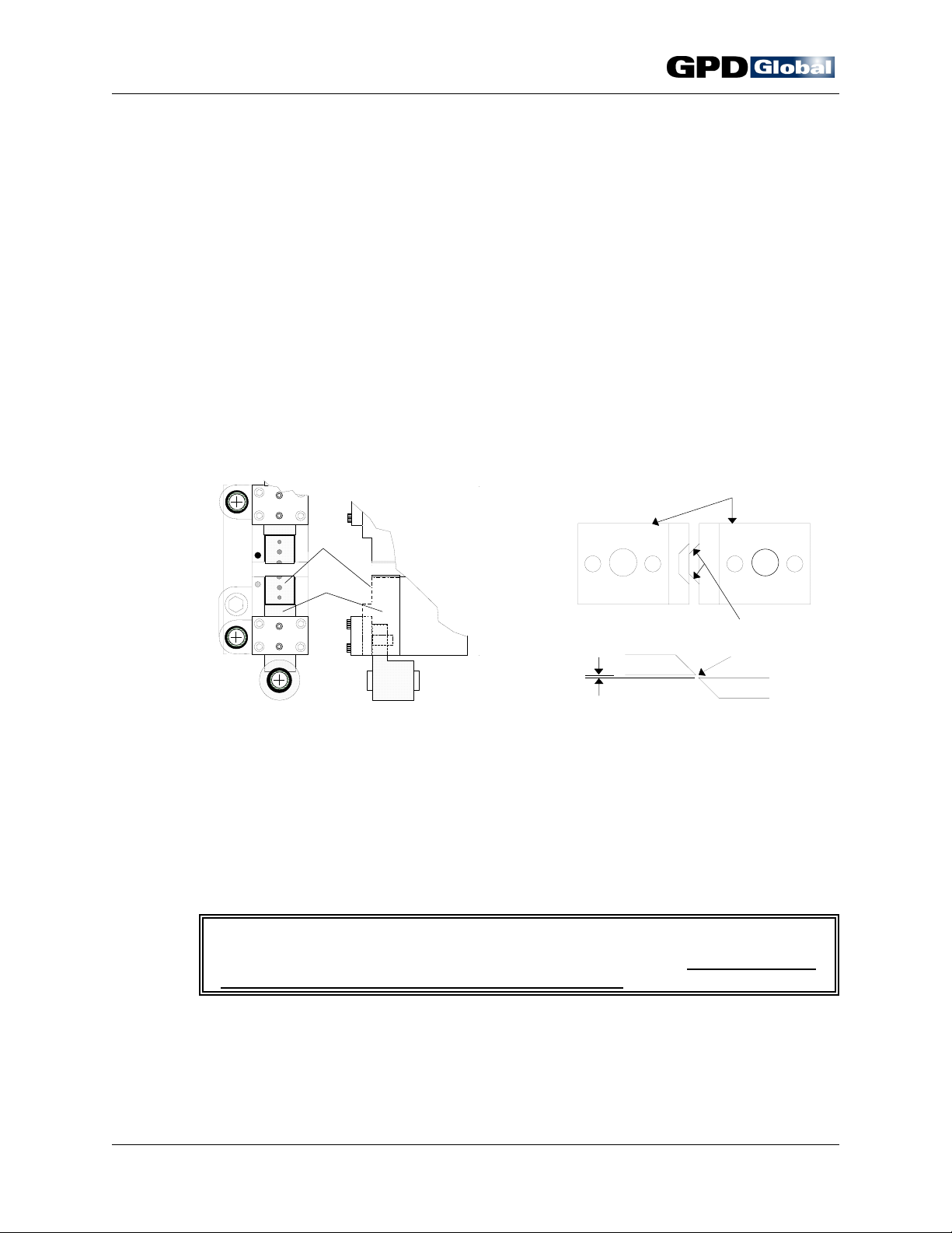
Die Installation
To properly position dies in Stations 1 and 2 and insure efficient machine use, follow
the die installation steps below. Be sure to test all adjustments with the manual hand
crank to verify that component body will not be damaged by forming dies or knives
and that the component is centered between the die station tooli ng.
1. Select dies. Refer to CF-9 Component Forming Die Catalog.
2. Clean dies and die slide locating sur faces per Preventive Maintenance "Daily"
instructions.
3. Install dies:
a. Refer to Die Markings (page 9) for proper locations.
b. Carefully place each die on proper die mounting surface (Figur e 8, Item
1) and bolt in place with a 5/8" (15.75 mm) screw. Then manuall y turn
machine's hand crank (page 6) until die block slides (Item 2) are in their
fully closed position.
T
1
B
1
1
2
2
3
Figure 8 Die Mounting Surface & Die Block
Slide
Figure 9 Die Alignment & Knife Clearance
c. Visually inspect alignment of die forming area to insure equal spacing on
both sides (Figure 9, Item 2).
d. Properly align die edges (Item 1) in relation to each other, centering each
die and knife in its station.
e. Adjust air gap clearance between dies (Item 3) to an even distance.
4. Check die alignment with hand cr ank prior to powering on machine.
I M P O R T A N T
The hand crank can be used to move mechanisms in reverse only during setup
and only when no components are loaded in machine.
5. Adjust die stations as necessary to obtain desired form and cut by aligni ng
components with dies and adjusti ng each station's height per the fol lowing
Station Adjustment and Component Alignment instructions.
14 GPD Global 09/30/92
CF-9 User's Guide
6. Install and adjust ejector brackets if
required. Required usage is indi cated for
123 4
each die, when appropriate, in the CF-9
Component Forming Die Cat al og. Certain
complicated lead forms require ejector
bracket installation to insure that
component does not remain in die. If
ejector bracket installation and adjustment
is not required, skip to Station Adjustment
on page 16.
Suggestion: Remove the small ejector
brackets when not required to simplify die
installation.
Two sets of ejector brackets are factory
Figure 10 Ejector Brackets
mounted on die Station 2 (Figure 10).
Each large ejector bracket (Item 1)
mounts to the Station 2 die block assembly with two screws (Item 4). Each
small ejector bracket (Item 2) mounts to the large ejector bracket with two
screws (Item 3).
2
B
2
Adjust for Component Body Thickness: Adjust for Component Body Height:
a. Loosen screws (Figure 10, Item 4). a. Loosen screws (Figure 10, Item 3).
b. Adjust each large ejector bracket b. Align center line of component body
(Item 1) to obtain an air gap of between small ejector brackets as
approximately 1/32" (0.794 mm) as illustrated in Figure 12.
illustrated in Figure 11. c. Tighten screws.
c. Tighten screws.
Large Ejector
Bracket
Small Ejector
Bracket
1/32"
1/32"
Component
Body Center
Line
Figure 11 Adjust Large Ejector Bracket
Figure 12 Adjust Small Ejector Bracket
09/30/92 GPD Global 15
2
CF-9 User's Guide
Station Adjustment
The CF-9's die stations are independentl y
adjustable to control for ming and cutting
locations. The action performed on component
leads by each die stat ion can be relocated from
a zero (0) position. GPD suggests setting the
zero (0) refer ence point at the machine's upright
plate (Figure 13, Item 1). This position also
corresponds with the lead wire point of
attachment to the tape. Refer to Taping
Specifications on page 30.
Backlash is eliminated during station adjustment
by three (3) beveled washers located on each
station adjusting bolt.
The standard micrometer scale (Item 2) attached to each station, indicates the
distance from the component's point of attachment on the tape to the point of station
action on the component lead. These scales are accurat e to .0005" (0.0127 mm).
1
Figure 13 Station Position Adjustment
Cut Lead Length
Station Position Station Action Location
Longest Fully ret racted Zero (0) position - the point at which
component attaches to tape.
Shortest Fully ext ended The point as near as possible to the
component body. Each extension
movement of station positi on creates a
correspondingly shorter lead length.
To adjust station position:
1. Position die block against
machine upright plate.
2. Turn on micrometer scale and
reset to zero (0).
3. Adjust die station using
supplied 1/4" T-handle wrench
Station 1
Adjusting Bolt
T
12
B
1
T
B
2
Station 2
Adjusting Bolt
in station die block adjusting
bolt (Figure 14).
a. To extend station, turn
wrench counterclockwise.
Figure 14
b. To retract station, turn wrench clockwise
Die Block Assembly Adjusting Bolts
.
16 GPD Global 09/30/92
CF-9 User's Guide
4. Record your micr ometer setting. Then machine can be setup quickly the next
time you process t he same component type.
5. Repeat Station Adjustment procedure for remaining die station.
Component Alignment
The CF-9 indexes exactly 1/2" (12.70 mm) every time,
however, component position relative to the t ape hole
may vary from your last run due to variances between
vendors or lots because:
• Distance from tape hole to component lead wire
may vary (Figure 15, Item 1) .
• Tape hole may be located betw een or under
component (Items 2 & 3).
A variance requires readjusting component alignment
with die stations — a simple matter of repositioning a
pulley (Figure 16, Item 4).
1
2
C A U T I O N
Testing component position relati ve to dies
MUST be done prior to automatic machine
operations.
To align components with die stations:
1. Manually index machine with hand crank just until components are centered
between dies and just before die touches component wires. Turn hand crank
slowly while visually inspecting for the relative position between components
and tape holes.
Figure 15 Component
Position Relative to Tape Hole
C A U T I O N
Dies should just start coming together - they should NOT be closed or
touching component.
C A U T I O N
DO NOT rotate mechanisms in reverse to check timing.
2. Loosen bolt in drive pulley (Figure 16, I tem 4) with supplied 3/16" wrench.
3. Manually turn pulley in either direction to cent rally position a component
between each die station.
4. Lock pulley in its new position by re-tightening the bol t.
5. Repeat step 1 to recheck tape alignment.
3
09/30/92 GPD Global 17
4
CF-9 User's Guide
Load Components
1. Press down on component tape pressure plate lever
(Figure 16, Item 3) to lift plate and open component
tape pathway.
2. Place tape's first hole ov er a pin on the transfer belt
(Item 1).
3. Release component tape pressure plate lever.
4. Using hand crank, manually index first component to
center of die Station 1.
5. Test all adjustments wit h the manual hand crank to
verify that component body will not be damaged by
forming dies or knives and that the component is
centered between the die station tooling.
1
Figure 16
Components
C A U T I O N
If machine is not properly adjusted, damage to components and dies may result.
6. If further adjustments ar e necessary, repeat Setup procedure on page 13.
2
Align & Load
3
Power On
1. Close and lock safety shi eld in place with safety shield lock (Figure 16, Item 2).
W A R N I N G
For operator's safety, do not operate machine w ithout safety shi e ld in place and
do not defeat the safety switch.
2. Set speed control to ze ro (0). If using optional accessories, such as the footswitch or
electronic component counter, set power switch to AUX position. The auxiliary mode
indicator will light if the CF-9 is plugged in.
3. Press reset button.
NOTE
As a safety feature, power is not automatically restored when safety shield i s
closed. Normal operations r esume when reset button is pushed.
4. Turn power switch to ON.
18 GPD Global 09/30/92

CF-9 User's Guide
Process Components
1. Position component reel or ammo pack of taped components in reel holder.
2. Load components. Refer to Load Components on page 18.
3. Close safety shiel d and press reset button.
4. Run machine very slowly to verify proper adjustment. Make furt her adjustments if
necessary to achieve desired results.
C A U T I O N
Testing component position relati ve to dies MUST be done prior to aut omatic
machine operations.
5. Increase machine speed rate to desir ed setting and process components.
6. To process a different component form or type, repeat Setup procedure on page 13.
Power Off
1. Set speed control to zero (0).
2. Turn power switch to OFF.
3. Remove all dies and clean wit h a rust inhibitor and lubricate mechanical moving
parts per Preventive Mai ntenance.
09/30/92 GPD Global 19

CF-9 User's Guide
This page left blank (almost).
20 GPD Global 09/30/92

1
CF-9 User's Guide
Preventive Maintenance
The preventive maintenance steps i n this section are intended prim arily for t he machine
operator, however , only qualified service or maintenance personnel should perform the steps
requiring access to the machine' s cabinet interior. The CF-9 is constructed so that pulleys,
belts, and bearings should not need to be replaced for many years, provided t he machine is
used according to instructions.
3
1
T
2
1
B
1
T
2
B
2
4
T
1
B
1
1
3
Figure 17 Die Block Assembly Lubrication Figure 18 Die Block Assembly Maintenance
Preventive Maintenance Schedule
Interval Location Action
Daily Dies/Knives Remove all dies/knives, inspect for wear, and clean
(8 hours of with rust inhibitor.
operation)
Die Block Assembly Inspect and lubricate eccentric shafts and bushings
Inspect for foreign matter or dust build-up. Brush
clean.
(Figure 17, Item 1) and die block guide shafts (Item 2)
with a light machine oil (3-in-1).
2
Place a drop of light machine oil (3-in-1) on slide
surfaces (Figure 17, Item 3) and in lubrication hole
(Item 4).
Apply oil to each of the four crank pins (Figure 18, Item
2).
Drive Belt Inspect belt pins and cogs for wear.
Schedule continues on followi ng page.
09/30/92 GPD Global 21

CF-9 User's Guide
Preventive Maintenance Schedule
(continued)
Interval Location Action
Monthly Die Block Assembly Clean die block adjusting bolt (Figure 18, Item 1) with
Inside Cabinet Inspect component drive belt for proper tension.
Yearly Safety Shield Apply a drop of light machine oil on each safety shield
solvent and apply a small amount of oil to its thread
near machine upright plate.
Spray molly grease on gears. Wipe off excess oil.
Lightly grease cam lobes and cam follower rollers.
Wipe off excess grease.
Check motor brushes and motor drive belt. Replace if
they appear worn or frayed.
CAUTION: DO NOT
drive belt without first loosening the motor mount
screws.
hinge. Wipe off excess oil.
attempt to remove or replace a
22 GPD Global 09/30/92
CF-9 User's Guide
Troubleshooting
The CF-9's hand crank is a useful troubleshooti ng feature enabling you t o manually move all
mechanisms. Simply insert the supplied Allen key in the hand crank port and turn. The hand
crank can be used to move mechanisms in reverse only during setup and only when no
components are loaded in machine.
Adjustment instructi ons for slide travel and sli de clearance follow the guide below.
Troubleshooting Guide
Problem Possible Cause Action
Dies, knives, and/or bushings Incorrect setup. Verify that proper tooling is being used. Refer
damaged or wearing to die catalog for correct die/knife and
prematurely. application combination.
Verify dies/knives are properly matc hed.
Verify that tooling is properly adjusted per
Setup.
Die/knife striking component. Inspect and set per Die Installation.
Ejector brackets not installed. Install ejector brackets per Die Installation
Foreign matter, dust build up. Inspect and clean per Preventive Maintenance.
Incorrect slide gap. Check gap with gauge block per Slide Travel.
Incorrect die alignment. Inspect and set per Die Installation.
Incorrect slide clearance. Inspect and set per Slide Clearance.
Incorrect size screw securing die. Secure die with correct size screw.
Machine performance Foreign matter, dust build up. Inspect and clean per Preventive Maintenance.
generally poor.
Component tape slipping off Belt studs missing or loose. Replace belt.
belt.
Inadequate lubrication. Oil per Preventive Maintenance.
Worn parts or dies. Inspect and replace as necessary.
Incorrect die alignment. Inspect and set per Die Installation.
Transfer belt timing. Set timing with drive pulley (page 6, I tem 5).
Incorrect size screw securing die. Secure die with correct size screw.
Transfer belt tension slack. Reset belt tension.
Misaligned reel holder. Realign or replace reel holder.
Missing pins on tape guide arm. Replace pins or tape guide arm.
Incorrect size screw securing die. Secure die with correct size screw.
instructions.
Guide continues on following page.
09/30/92 GPD Global 23

CF-9 User's Guide
Troubleshooting Guide
(continued)
Problem Possible Cause Action
Machine cutting improperly. Slide clearance too large. Reset slide t r avel per Slide Clearance.
Incorrect slide gap. Set gap per Slide Travel.
Worn eccentric shaft bushing. Replace bushing.
Worn dies. Replace or repair dies.
Incorrect size screw securing die. Secure die with correct size screw.
No machine movement. Broken drive belt. Replace drive belt.
Blown fuse. Replace fuse.
NOTE: As a preventive measure, turn speed
control to zero (0) before turning machine on.
Power not restored after closing safety Press reset button.
shield.
Machine not plugged in. Plug machine in per Specifications.
Machine not turned on. Turn machine on per Operating Instructions.
Speed control set to zero (0). Set speed control to appropriate operating
Drive pulley set screws loose. Tighten set screws.
Incorrect size screw securing die. Secure die with correct size screw.
speed.
Slide Travel
To adjust slide travel:
1. Unplug machine.
2. Insert provided 1.934" gauge block (Figure
19, Item 1) while manuall y turning
machine's hand crank until die block slides
(Item 5) are fully closed.
3. Check for gauge block movement. If
movement does not
Clearance. If movement does
occur, proceed to Slide
occur, adjust
the crank adjuster (Item 3):
a. Loosen crank set screws (Item 2).
b. Use wrench in crank adjustor holes
(Item 4) to rotate crank adjuster until
gauge block no longer moves.
c. Tighten eccentric crank screws.
d. Replace bushings if movement cannot be elimi nated through adjustment.
1
Figure 19
T
1
1.934"
B
1
Die Block Assembly Slide Travel
2
3
4
5
24 GPD Global 09/30/92

6
7
CF-9 User's Guide
Slide Clearance
To adjust slide clearance:
1
1. Remove die block assembly. Station 1 die
block assembly is illustrated in Figure 20.
2
a. Remove from the CF-9:
• Tape exit chute
• Component transfer belt
3
• Transfer belt guide and
component tape pressure plate
(located on either side of
4
transfer belt)
b. Raise die block approximately 1"
(25.40 mm) from machine upright
Figure 20 Die Block Assembly Slide Clearance
plate using machine's die block
adjusting bolt (Figure 20, Item 3).
c. Remove mounting screws from micrometer scale's lower mounting block.
d. Turn die block adjusting bolt until die block no longer moves and then slide die block
straight off machine.
T
1
B
1
5
9
8
2. Clean parts.
a. Remove and discard set screws in cover plate (Figure 20, I tem 6).
b. Remove slide (Item 9) from die block.
c. Use a degreaser (brake cleaner) to remove all oil fr om slide, die block, and wear
plate (Items 9, 8, and 7).
C A U T I O N
Do not expose micrometer scales t o degreaser (brake cleaner) as it clouds the
clear face plate.
d. Measure all surfaces for wear and inspect for scratches and gouges. Replace parts
if raised material is visible on working plane.
e. Lightly st one all surfaces.
f. Blow dry all parts.
3. Reassemble die block.
a. Install slides in die block.
NOTE
Position slide with the eccentric bushing in the eccentric crank (Item 1) in die
block's top half (T1 or T2).
b. Slip wear plate face up between cover plate and slide.
c. Align wear plate counter sunk holes with cover plate set screws.
d. Install new set screws and lightly tighten.
e. With slides in closed position, locate a dial indicator on die mounting surfaces (Item
09/30/92 GPD Global 25

CF-9 User's Guide
8) and compare heights. For mated dies to function together properl y, replace dies
and/or slide blocks if heights ar e not within .0005" (0.0127 mm) of each other.
4. Set clearance.
a. Loosen cover plate's inner set screw (Figure 20, Item 4) approximately a quarter turn.
b. Slowly loosen outer set screw (Item 5) just until slide moves freely.
c. Tighten inner set screw unt il a slight drag is felt.
d. Install die screw in slide to prevent sli de from slipping out of die block.
e. Position slide flush wi th back side of die block.
f. Locate a dial indicator on the slide's die mounting surface and set the clearance to
.0007 - .001" (.0178 - .0254 mm) by pulling up on die screw. After clearance is set,
verify that slide moves freely.
NOTE
If slide does not move freely, loosen outer set screw slightly. Recheck clearance.
g. Secure screws by applying modest amount of penet rating thread locker (Loct ite
#290).
h. Repeat step 4. for remaining slides.
5. Lubricate parts.
a. Generously apply 5 weight oil (3-in-1)
1
to all sides of slide and crank pin
(Figure 21, Item 3), working in
thoroughly.
C A U T I O N
D
O NOT USE A PENETRATING OIL
(WD-40)
BLOCK SEIZURE
AS THIS WILL CAUSE DIE
.
2
T
1
B
1
1
b. Sparingly apply oil to eccentr ic crank
shafts (Item 1) and die block guide
shafts (Item 2).
6. Reinstall die block assembly.
a. Slide die block assembly straight onto machine until die block adjusting bolt reaches
hole.
b. Thread die block adjusting bolt into hole.
c. Replace mounting screws for digital scale's lower mounting block.
Figure 21 Die Block Assembly Lubrication
3
26 GPD Global 09/30/92

CF-9 User's Guide
d. Position die block assembly approximately 1" (25.40 mm) from machine upright plate
using die block adjusting bolt.
e. Lay machine on its back cov e r with die blocks up and cabinet's back air vent clear.
Run machine in this position for appr oximately one (1) hour to allow oil to distribute
evenly. Dur ing this time period, slowly increase machine speed and check cover
plate and die block for heat.
C A U T I O N
I
F EXCESSIVE HEAT IS DETECTED OR A SQUEAK IS HEARD, STOP THE MACHINE. REPEAT
COMPLETE SLIDE CLEARANCE PROCEDURE
f. Reassemble the following:
• Digital scale lower mounting block screws
• Belt guide and pressure plate
• Component transfer belt (Adj ust so belt is taut.)
• Tape exit chute
• Die screws
g. Reset slide travel adjustment - refer to Slide Travel on page 24.
.
09/30/92 GPD Global 27

CF-9 User's Guide
This page left blank (almost).
28 GPD Global 09/30/92

L
L
2
Specifications
Power Requirements
120 Volt Model 230 Volt Model
120 Volts
Neutral
Safety (Eart h) Ground
5 Amps
60 Hz Safety (Eart h) Ground
1
230 Volts
2.5 Amps
50/60 Hz
CF-9 User's Guide
Dimensions
Height........
Length .......
Width ........
Standard CF-9
12.00 inches
(304.80 mm)
13.25 inches
(336.55 mm)
13.50 inches
(342.90 mm)
CF-9 with
Reel Holder
18.62 inches 29.50 inches
(472.95 mm) (749.30 mm)
13.25 inches 26.00 inches
(336.55 mm) (660.40 mm)
28.00 inches 39.00 inches
(711.20 mm) (990.60 mm)
CF-9
Work Station
Weight
Standard CF-9 .............................................58 lbs. (26.31 kg)
Capacities
Production Rate
The CF-9 is capable of forming and cutting up to 25,000 components per hour.
Micrometer Scale
Display increments to .0005" (0.0127 mm)
±.002" Repeatability
09/30/92 GPD Global 29

CF-9 User's Guide
Taping Specifications
The CF-9 will process components if taped to the E.I.A. standards listed below for taping of
radial components AND
cases, standard tooling may work with l ess than this minimum operating clear ance.
Custom tooling or custom taping may be required in cer tain instances.
there is a minimum of .300" (7. 62 mm) operating clearance. In some
Y
X
C
A
Figure 22 GPD's CF-9 Taping Specifications
B
GPD CF-9
Taping Specification Li mits
Symbol Definition Inch MM
X Height to seating plane (formed leads) .300 ± .010 7.62 ± 0.25
Y Operating Clearance - All dies except style 8A .300 minimum 7.62 minimum
Seating plane (straight leads)
8A style die .350 minimum 8.89 minimum
E.I.A.
Taping Specification Li mits
Symbol Definition Inch MM
A Component centering .250 ± .012 6.35 ± 0.30
B Sprocket hole pitch .500 ± .012 12.70 ± 0.30
C Carrier tape width .710 + .039 18.00 + 1.00
to to
—.020 —0.50
30 GPD Global 09/30/92

CF-9 User's Guide
Suggested Spare Part Kits
The following suggested spare parts kits for the GPD CF-9 list the items included in each kit and
the GPD part number for each item.
GPD Part
Number Part Description Qty.
925-1-2 120V 60Hz Spare Parts Kit 1
(consists of the followi ng items)
BELTS
901-3-101 Transfer Belt 1
D0001 Motor Belt 1
INDEX WHEEL ASSEMBLY
806-1-3 Roller 16
G1007 Retaining Ring 16
FUSE
4300-0026 Fuse MDL 5A, Slow Blow 1
925-1-3 230V 50/60Hz Spare Parts Kit 1
(consists of the followi ng items)
BELTS
901-3-101 Transfer Belt 1
D0001 Motor Belt 1
INDEX WHEEL ASSEMBLY
806-1-3 Roller 16
G1007 Retaining Ring 16
FUSE
4300-0025 Fuse MDL 2.5A, Slow Blow 1
09/30/92 GPD Global 31

CF-9 User's Guide
Suggested Spare Parts
The following suggested spare parts listing is for those customers in locations where next day
delivery service from the USA in not avai lable.
GPD Part
Number Part Description Qty.
120V 60 Hz Spare Parts
G1003 Circlip 10
L0503 Bushing 2
L0601 Bushing 2
2200-0008 Speed Control, 120V, 60 Hz 1
821-4-12 Circlip Plier 1
901-1-102 Die Station #2 1
925-1-2 Spare Parts Kit, 120V 1
230V 50/60 Hz Spare Parts
G1003 Circlip 10
L0503 Bushing 2
L0601 Bushing 2
2200-0014 Speed Control, 230V, 50/60 Hz 1
821-4-12 Circlip Plier 1
901-1-102 Die Station #2 1
925-1-3 Spare Parts Kit, 230V 1
32 GPD Global 09/30/92

CF-9 User's Guide
Appendices
Table of Contents
Appendix A - Die Informati on ................................................... 35
Forming Style Series .................................................... 35
Die Number............................................................ 35
Appendix B - Common CF-9 Lead Forms ......................................... 37
Appendix C - CF-9 Accessories ................................................. 39
Lead Forming Dies ...................................................... 39
Component Detection System ............................................. 39
Electronic Component Counter ............................................ 39
Footswitch ............................................................. 40
Lazy Susan (Rotating Machine Platform)..................................... 40
Loose/Bulk Component Feeder ............................................ 41
Taped Component Re-Reeler ............................................. 41
Work Station ........................................................... 41
Appendix D - Electrical Schematic & Assembly Drawing ............................. 43
09/30/92 GPD Global 33

CF-9 User's Guide
This page left blank (almost).
34 GPD Global 09/30/92

9
D
F
905-4AF905-3JA
905-3H
CF-9 User's Guide
Appendix A - Die Information
Forming Style Series
The forming style series is stamped on the right hand side of each die and knife (Figure 23):
T
2
1
Forming
Style Series
B 1
2
Figure 23
Forming Style Series
Die Number
Forming Style Series
Number
Description
1 Die, 3 Lead Radial (typically TO-92), In-Line
2 Die, 2 Lead Radial, Stand-Off, Opposing Dimple
2C Die, 2 Lead Radial, Lock-In Stand-Off, Opposing Dimple
3 Die, 2 Lead Radial, Lock-In Stand-Off
4A Die, 2 Lead Radial, Spreading
4B Die, 2 Lead Radial, Reducing
5Knife
7 * Die, 2 Lead Radial, 90° Bend
8A Die, 2 Lead Radial, Spreading, Lock- In Stand-Off
8B Die, 2 Lead Radial, Reducing, Lock-I n Stand-Off
10 Die, 2 Lead Radial, Stand-Off Lock-In
11 Die, 2 Lead Radial, Flush Mount Lock-In
* NOTE: GPD has an adjustable
90° bend 7-styl e die
available. Call GPD for details. (970) 245-0408
ie Type
05-3JA
Forming style
series
905-4A
T
3 4A
1
JA
T
1
F
T
3H
1
Wire to hole
specification
Forming
dimension
Figure 24 Examples of Die Numbers Figure 25 Examples of Die Number Location
B 1
JA
For further die specificati on details, refer to the CF-9 Component Forming Die Catal og.
B 1 3 4A
F
B 1 3H
09/30/92 GPD Global 35

CF-9 User's Guide
This page left blank (almost).
36 GPD Global 09/30/92

CF-9 User's Guide
Appendix B - Common CF-9 Lead Forms
Some examples of the most common component forms produced by the CF-9 are shown below.
Die Form Die Form
Form
Number Description Form Number Description
905-1 Middl e Lead Offset 905-4A Spread Form
with Lock-In Form
905-1A Middle Lead Offset 905-4B Reducing Form
Form
905-1CA In-Line Lock- In 905-7 90° Angle Bend
Stand-Off Form
905-1H4 Middle Lead Offset 905-8A Spread Form with
905-1H5 with 3 Lead Lock-In Lock-In Stand-Off
905-1L4 Form
905-2 Stand-Off with 905-8B Reducing Form
Opposing Dimple with Lock-I n StandForm Off
905-2C Lock-In Stand-Off 905-10 Low Profile Stand-
with Opposing Off Lock-In Form
Dimple Form
905-3 Lock-In Stand-Off 905-11 Flush Mount Lock-
Form In Form
09/30/92 GPD Global 37

CF-9 User's Guide
This page left blank (almost).
38 GPD Global 09/30/92

CF-9 User's Guide
Appendix C - CF-9 Accessories
The following optional accessories for GPD's CF-9 are specifically designed to help you increase
production and profit.
Lead Forming Dies
The CF-9 operates on a system of dies and die blocks. Each combination is designed to form a
specific lead configuration. Numerous standard and special CF-9 Lead Forming Die sets are
available to provi de a variety of component forms and lead configurations such as lock-ins,
standoffs, standoff lock-ins, spreading, reducing, and ninety-degree bends. Many different die
sets for various transi stor hole patterns are also av ailable. Dies are avail able to form two leaded
components with center-to-center dimensions up to .400" (10.16 mm) as well as 3-leaded TO-92
transistors. All CF-9 dies will also work on the GPD CF-10 Loose/Bulk Component Lead
Former.
Each die is clearly identified and color coded. This color codi ng, in combination with t he roll
pins, insures against installation mistakes. Changing dies i s a matter of one screw. Remove
the die you wish to change and replace it wit h a new die.
Standard dies are secured in place w ith 10-32x5/8" screw s - these accompany the CF-9
machine. When a special die requires a longer screw, it is supplied with the die.
Most cutting and formi ng needs are covered with the st andard dies we offer. However, if you
have unusual requirements, GPD will be pleased to design custom dies for you. Your GPD
representative will be happy to assist you with any custom die orders.
Component Detection System
The CF-9's Component Detection System option helps prevent die breakage by identifying bent
components on tape and stopping CF-9 operations prior to a misaligned component entering the
first die station.
Electronic Component Counter
The electronic counter is an automati c component counter that unerringly detects even the
smallest component on the CF-9. I nstallation is simple and fast so t hat one counter can easily
be moved from one CF-9 to another as counti ng requirements change.
The counter has two operation modes, pr e-determining and totalizing. You can preset the total
number of components you wish to run, and the counter's predetermining mode automatically
shuts off the machine when the preset count is reached. The counter's totalizing mode gives
you a cumulativ e count of all the components the machine has processed.
09/30/92 GPD Global 39

CF-9 User's Guide
Counter Installation:
1. Remove cap screw (Figure 26, Item 2).
2. Slide counter bracket onto dowel pin (Item 1).
Replace and tighten cap screw to secure counter
mounting.
3. Place counter on top of CF-9 cabinet.
4. Plug counter bracket wiring harness into counter's
back panel.
5. Plug counter power cord w ith twist lock plug i nto
accessory outlet on CF-9's control panel.
6. Plug counter's regular pow er cord into a power
source per Specifications.
Figure 26 Electronic Component Counter
Footswitch
The optional footswitch is a real operator convenience. After easily installing the footswitch, the
operator need only position the CF-9 power sw itch to the AUX position and depr ess the
footswitch to operate the machine.
Installation
1
2
Footswitch Installation:
1. Turn power switch to off.
2. Set speed control to zero (0).
3. Insert footswitch plug into accessory outlet on CF-9's control panel and turn clockwise
lock in place.
4. Set power switch to AUX position. The auxiliary mode indicator lights.
5. Set speed control to desired operating speed.
To remove footswitch, tu rn plug counterclockwise
.
to
Lazy Susan (Rotating Machine Platform)
This rotating, circular platform allows the operator to easily rotate the entire machine t o gain
better access for setup, die changes, and normal maintenance. The Lazy Susan has been
specifically const ructed to operate smoothly under the CF-9's wei ght. Covered in ridged, ant istatic material, this turntable holds the machine securely in any position with its unique graphite,
anti-drift system.
40 GPD Global 09/30/92

CF-9 User's Guide
Loose/Bulk Component Feeder
Process both taped and loose radial components on one machine by using the Loose/Bulk
Component Feeder. This accessory provides the perfect soluti on when you need to form a
relatively small number of components and they are not available or are too expensive on tape.
Load up to ten (10) components in a magazine, place magazine in st aging fixture, and then
lightly press each component down to the top of staging fixture. Remove the magazine and your
components are perfectly aligned, ready to feed directly into the CF-9 in exactly the same
manner as you would feed a strip of taped components. There are four magazine sizes based
on center-to-center requirements with a 1" (25.40 mm) minimum lead length requirement.
Taped Component Re-Reeler
Now you can form and r e-reel radial components for automatic insertion in one operation. With
this accessory, the CF-9 feeds taped components into the first die station, forms t hem, skips the
normal trim operation and sends components straight to the Re-Reel er. Special flattening
blocks can be inserted in the trimming station if additional dimple alignment is required. The rereeler automatically reloads the taped component s back on a reel after the forming process i s
complete.
The optional CF-9 Taped Component Re-Reeler has been specially modified with a slip clutch
assembly on the dri ve motor shaft to allow the operator to adjust dri ve shaft tension. Increasing
shaft tension causes taped components to wind tighter. Decreasing the tension results in more
loosely wound components.
Work Station
The CF-9, dies, and various operational tools can all be mounted on this speci ally construct ed
work station whi ch provides vibration fr ee operations and optimum storage space. The CF-9
Work Station's heavy duty construction includes a 3/8" (9.53 mm) thick aluminum top, a 1"
(25.40 mm) tubular steel frame, and inlaid steel panels.
09/30/92 GPD Global 41

CF-9 User's Guide
This page left blank (almost).
42 GPD Global 09/30/92

CF-9 User's Guide
Appendix D - Electrical Schematic & Assembly Drawing
Drawing Title Drawing Number
CF-9 Electrical Schematic .......................................... 0098001A
CF-9 Electrical Assembly Drawing.................................... 0098002A
09/30/92 GPD Global 43

CF-9 User's Guide
This page left blank (almost).
44 GPD Global 09/30/92


A
Accessories 18, 39
Component Detection System 13, 39
Electronic Component Counter 18, 39
Footswitch 18, 40
Lazy Susan 11, 40
Lead Forming Dies 39
Loose/Bulk Component Feeder 41
Taped Component Re-Reeler 41
Work Station 11, 41
Accessory
Equipment 11
Outlet 7, 40
Adjustment 8
Component Alignment 17
Component Body Height 15
Component Body Thickness 15
Hand Crank 6, 13, 14, 17, 18
Slide Clearance 25
Slide Travel 24
Station 16
Tape Hole to Lead 17
Ammo Pack 5, 19
AUX 18, 40
B
B1 9
B2 9
Belt Tension Release Bar 6
C
Capacities 29
Micrometer 29
Production Rate 29
Component
3 Lead Radial 35, 37
Alignment 17
Ammo Pack 5, 19
Bent 13
Bin 5, 11
Body Height 15
Body Thickness 15
Counter 39
CF-9 User's Guide
Index
Feeder 41
Leads 13
Load 18
Loose 41
Pathway 18
Pitch 13
Process 19
Re-Reeler 41
Reel 5, 19
Reel Tape 13
Tape Pressure Plate Lever 6
Taped 5
TO-92 Transistors 3
Transfer Belt 6
Component Detection System 13, 39
Control Panel 7
Accessory Outlet 7
Fuse 7
Power Switch 7, 13, 18, 19
Reset Button 7, 18, 19
Speed Control 7, 11, 18, 19
Cover Plate 25
Crank
Adjuster 24
Pin 26
Shaft 8
Cycles per hour 7
D
Die
Breakage 13
Custom 30
Die Mounting Surface 14
Functions 3
Information 35
Installation 9, 14
Markings 9
Number 35
Sets 2
Stations 1, 5, 8
Die Block 8
Die Block Assembly 5, 25
Adjusting Bolt 8, 16, 25
Cover Plate 8
Crank Adjuster 8
Crank Shaft 8
09/30/92 GPD Global 45

CF-9 User's Guide
Die Block 8
Die Mounting Area 8
Eccentric Crank 8
Guide Shaft 8, 26
Micrometer Scale Indicator 8, 16
Slide 8, 14
Wear Plate 8
Die Markings
Forming Style Series 9, 35
Installation Color Dot 9
Installation Marking 9
Dimensions 29
Drive Pulley 6, 17
E
E.I.A. Standards 30
Eccentric
Crank 8, 25
Crank Shafts 26
Ejector Brackets 15
Electrical Schematic 43
Electronic Component Counter 18, 39
F
Flattening Blocks 5, 41
Footswitch 18, 40
Forming Style Series 9, 35
Forms
Complicated Lead 15
Lead 3, 37
Function
CF-9 3
Dies 3
Station 1 5
Station 2 4, 5
Fuse 7
I
Indexing System 1
Installation 11
Color Dot 9
Die 14
Die Markings 9
Die Position 9
Ejector Brackets 15
Electronic Component Counter 40
Footswitch 40
Marking 9
K
Knives 9
L
Lazy Susan 11, 40
Lead 13, 17
3 Lead Radial 35, 37
Center-to-Center Dimensions 3
Complicated Lead 15
Cut Length 8, 16
Diameters 3
Forming Dies 39
Forms 3, 37
Point of Attachment 16
Load Components 18, 19
Loose/Bulk Component Feeder 41
M
Machine Upright Plate 16, 25
Maintenance 21
Micrometer Scale 1, 8, 16, 25, 29
G
Gauge Block 24
Guide Shaft 8
Operating
Clearance 30
Instructions 13
H
Hand Crank 6, 13, 14, 17, 18, 23
46 GPD Global 09/30/92
O

CF-9 User's Guide
P
Part Identification 5
Power
Off 19
On 18
Requirements 29
Power Switch 7, 13, 18, 19
AUX 18, 40
Pressure Plate Lever 6, 18
Preventive Maintenance 21
Process Components 19
Production Rate 29
R
Reel Holder 5, 11, 19
Reset Button 7, 18, 19
S
Safety
Shield 6, 11, 18, 19
Shield Lock 6, 18
Screw Sizes 11, 14, 39
Serial Number 11
Setup 13
Slide Clearance 25
Slide Travel 24
Gauge Block 24
Spare Parts 31
Specifications 29
Taping 30
Speed Control 7, 11, 18, 19
Station
Action 16
Adjustment 16
Guide Shaft 8
Position 16
Station 1 5, 14
Station 2 4, 5, 14, 15
Work 41
Hole-to-Hole Spacings 3
Operating Clearance 30
Pressure Plate Lever 6
Roller Guide 1, 5
Taped Component Re-Reeler 41
Taped Components 5
Custom 30
Taping Specifications 30
Tension Release Bar 6
Theory of Operation 4
Transfer Belt 6, 18
Troubleshooting 23
Guide 23
Hand Crank 23
W
Wear Plate 25
Weight 29
Work Station 11, 41
Z
Zero (0) Reference Point 16
T
T1 9, 25
T2 9, 25
Tape 13
Exit Chute 1, 5
Guide Arm 5, 11
Hole to Lead Distance 17
09/30/92 GPD Global 47


CF-9
Radial Lead Forming Machine
Bills of Material
&
Exploded Views
Version 2.2
June 3, 2014
Prepared by
GPD Documentation Department
Copyright (C) 1992, 1996, 2002, 2007, 2014 GPD Global
GPD Global
611 Hollingsworth Street
Grand Junction, CO 81505
(970) 245-0408 FAX (970) 245-9674
CF-9 Bills of Material & Exploded Views
Part No. 901-1-02
®
All Rights Reserved
®


CF-9 BOM & Exploded Views
11-03-11
SPARE PARTS KIT, 120V
Effective As of: 11-03-11
ITEM* PART#............... DESCRIPTION.............. QTY....... UM
1 SACAN1032062 DIE SCREW 6 EA
2 901-3-10 TRANSFER BELT 1 EA
3 4300-0026 FUSE,SLOW BLOW 3 EA
Bill of Material for Assembly 925-1-2
N.S. - Not Shown N.S.S. - Not Sold Separately
Page 36 General Production Devices 06/03/14


 Loading...