


CF-10 Option
Operating Instructions
for
• High-Low Track Sensors
with Vibratory Bowl
• Single Feed Selection
Version 1.2
May 27, 2009
Prepared by
GPD Global® Documentation Department
Copyright (C) 2009 GPD Global®
Grand Junction, CO, USA 81505
GPD Part# 1001-1-03
CF-10 Option Operating Instructions
All Rights Reserved
GPD Global®
611 Hollingsworth Street
tel: +1.970.245.0408
fax: +1.970.245.9674

CF-10 Option
Operating Instructions
INTRODUCTION
This document is intended for use by setup and operator personnel and accompanies the GPD CF-10
when equipped with a combination of the following options:
GPD Part No. Description
1022-200 High-Low Track Sensors Option with Vibratory Bowl, 120 Volt
1022-201 High-Low Track Sensors Option with Vibratory Bowl, 230 Volt
1022-101 Single Feed Selection Option
High-Low Track Sensors Option (External Device Detection)
empty" conditions in the CF-10's in-line feeder track and controls power to the CF-10 and optional
vibratory bowl (or other external device) in relation to these track conditions.
This option's
• A full track condition is detected;
• a delay for the amount of time set with the TRACK FULL DELAY occurs;
• the vibratory bowl (or other external device) stops;
• components continue feeding into the CF-10 decreasing the track's component count to a point below
the full track sensor;
• and the vibratory bowl (or other external device) resumes operations.
When a
shuttle in open position. The CF-10 automatically resets after the track is filled with components (track full
condition).
full track
near empty track
Single Feed Selection Option
switch to control the CF-10. The operator is in control of synchronizing component loading with
component processing. The machine cycles once for every depression of the foot switch and stops in the
correct position to wait for the next component to be loaded. The CF-10 automatically resets each time
the operator releases the foot switch.
theory of operation is as follows:
is detected, the High-Low Track option turns the CF-10 off with the dies and
- enables operator to hand feed components while using the foot
- detects both "full" and "near
FUNCTION
The High-Low Track Sensors option performs the following functions:
• Detect a full track condition in the CF-10's in-line feeder track.
• Detect a near empty condition (a low component count) in the CF-10's in-line feeder track.
• Stops CF-10 operations when the in-line feeder track contains a minimal quantity of radial
components.
The Single Feed Selection option performs the following functions:
• Enables operator to synchronize single component loading and processing.
• Automatically resets CF-10 for next component processing cycle.
05/27/09 GPD Global® Page 1
SAFETY INSTRUCTIONS
•
CAUTION:
requires the operator to properly adjust delay times and operating speeds both in relation to each
other and to component dimensions and properties.
•
CAUTION:
Improper operation will result.
•
CAUTION:
damage to the equipment.
To achieve optimum production while avoiding possible damage to the equipment
DO NOT operate the CF-10 with more than one option switch in the option select position.
GPD suggests an operator be present during machine operations to avoid possible
INSTALLATION
The High-Low Track Sensors and Single Feed Selection options are factory installed on the CF-10.
PART IDENTIFICATION
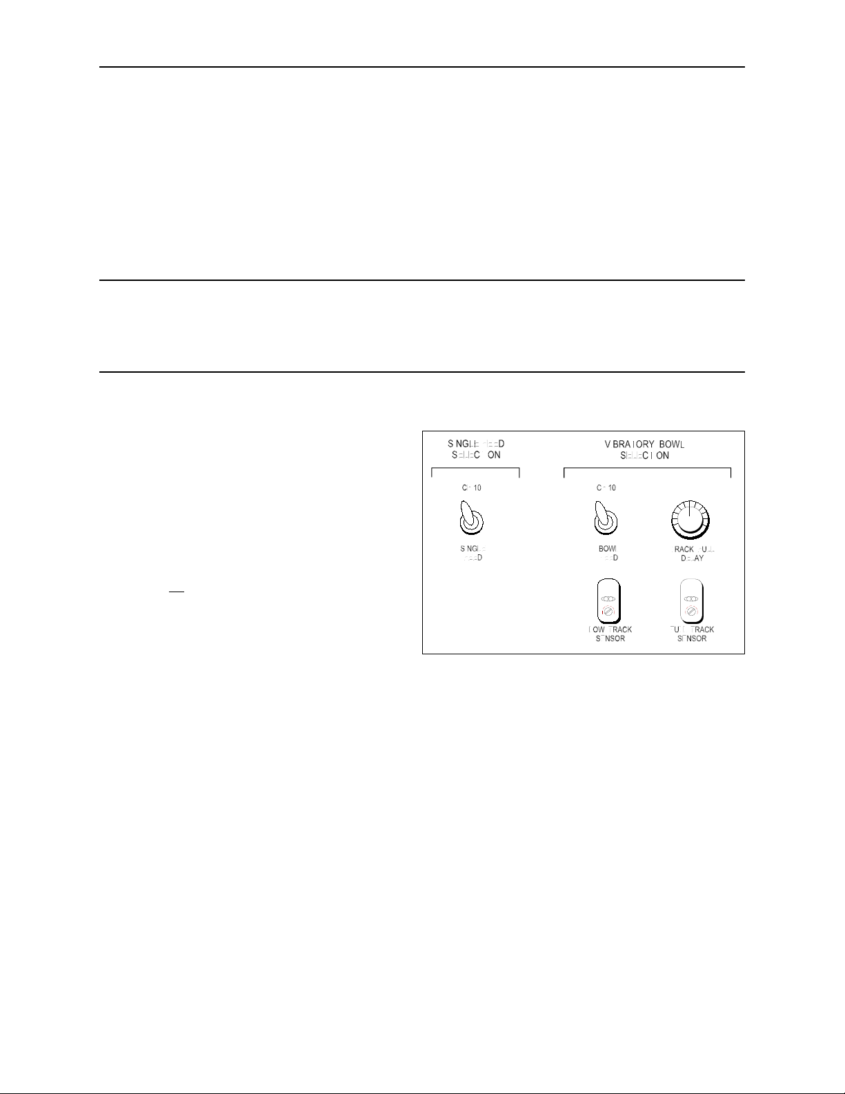
Most of the CF-10 option controls are located on
the machine's left cabinet panel. Refer to the
figure at right for an illustrated example of these
controls.
SINGLE FEED SELECTION
CONTROLS
CF-10
When
all
option switches are in the "CF-10"
position, the options are disabled and the
CF-10 operates in its standard manner.
SINGLE FEED
When the single feed selection switch is in
the SINGLE FEED position, the single feed option is selected.
CAUTION:
Improper operation will result.
DO NOT operate the CF-10 with more than one option switch in the option select position.
VIBRATORY BOWL SELECTION CONTROLS
TRACK FULL DELAY
The TRACK FULL DELAY control knob regulates the amount of delay time between the occurrence
of a track full condition and the vibratory bowl being shut off. Increasing the TRACK FULL DELAY
setting increases the delay time between a track full condition and the machine stopping.
FULL TRACK SENSOR
The FULL TRACK sensor is located at the in-line feeder track entrance, while its adjustment control is
found under the EXTERNAL DEVICE SELECTION label (refer to above figure).
When a track full condition occurs, a delay for the amount of time set with the TRACK FULL DELAY
occurs; the vibratory bowl stops; components continue feeding into the CF-10 decreasing the track's
Page 2 GPD Global® 01/18/93

component count to a point below the full track sensor; and then the vibratory bowl resumes
operations.
If the CF-10 is already shut off when the full track condition occurs, the following sequence of events
occur: the CF-10 remains off, the bowl turns off, and then the CF-10 resumes running.
CF-10
all
When
operates in its standard manner.
BOWL FEED
When the Bowl Feed switch is in the BOWL FEED position, the High-Low Track Sensor option is
selected.
option switches are in the "CF-10" position, the options are disabled and the CF-10
CAUTION:
Improper operation will result.
LOW TRACK SENSOR
The LOW TRACK sensor is located at the end of the in-line feeder track, while its adjustment control
is found under the "External Device Selection" label (refer to above figure). When a minimal quantity
of components are present on the in-line feeder track, the LOW TRACK sensor shuts the CF-10 off.
FINE SPEED CONTROL
The FINE SPEED CONTROL is a part of the CF-10 speed control knob located on the CF-10's front
cabinet control panel. The CF-10 speed control consists of two knobs: a large single-turn, knurled
knob for course speed settings and a small 9-turn knob for fine speed settings. The ratio of fine to
course is 9 to 1.
DO NOT operate CF-10 with more than one option switch in the option select position.
OPERATING INSTRUCTIONS
High-Low Track Sensor
To operate the CF-10 with the High-Low Track Sensor option:
1. Setup the CF-10:
a. Install the CF-10 shuttle.
b. Adjust shuttle and track heights.
c. Make course die adjustments.
2. Prepare to feed components to the CF-10:
a. Turn on the CF-10's in-line feeder track.
b. Place components in the optional vibratory bowl.
c. Close the safety shield and press the CF-10's restart button.
d. Make sure the Vibratory Bowl Selection switch is in the BOWL FEED position and the Single
Feed Selection switch is in the CF-10 position.
e. Turn on the vibratory bowl.
f. Let the in-line feeder track fill with components.
01/18/93 GPD Global® Page 3

3. Adjust the CF-10 to the initial test components:
a. Manually index the first component to the CF-10's first die station.
b. Make fine adjustments to the first die station to attain proper processing height.
c. Repeat the indexing and fine adjustment steps for die stations 2 and 3.
CAUTION:
requires the operator to properly adjust delay times and operating speeds both in relation to each
other and to component dimensions and properties.
4. Automatically feed components into the CF-10 and adjust the optional vibratory bowl:
a. Set the CF-10 to a low speed. Components will feed until they reach the shuttle and then fill the
b. Fine tune the vibratory bowl feed rate to maintain, as close as possible, a near-full track without
c. Close the safety shield and press the CF-10's restart button.
5. To run the last components in a job:
a. Wait until the last few components reach the LOW TRACK sensor.
b. Turn off the vibratory bowl
c. Flip both SINGLE FEED and BOWL FEED switches to their CF-10 position. The last
To achieve optimum production while avoiding possible damage to the equipment
track. Wait for the track to completely fill with components.
the bowl constantly starting and stopping.
components finish processing.
Single Feed Selection
To operate the CF-10 with the Single Feed Selection option:
1. Setup the CF-10:
a. Install the CF-10 shuttle.
b. Adjust shuttle and track heights.
c. Make course die adjustments.
2. Prepare to feed components to the CF-10:
a. Make sure the Single Feed Selection switch is in the SINGLE FEED position and the Vibratory
Bowl Selection switch is in the CF-10 position.
b. Remove the CF-10's top guide.
c. Close the safety shield and press the CF-10's restart button.
3. Process components:
a. Using proper tooling, insert components into the guide shuttle.
b. Depress the foot switch and do not release until cycle is complete. One component cycle is
activated and component exits normally.
NOTE:
is released. If released prior to cycle completion, improper forming or damage to the component may
result.
c. Release foot switch. Machine resets for next cycle. Repeat step 3 as often as necessary to
Hold foot switch down until cycle is completed. Machine stops immediately when foot switch
process components.
Page 4 GPD Global® 01/18/93

ADJUSTMENTS
If the TRACK FULL or LOW TRACK sensors for the High-Low Track Sensor option need to be adjusted,
follow the procedure below.
Adjust Fiber Optic Through Beam Sensor
1. Be sure the light source and receiver are physically aligned in
an approximately straight line.
2. In the presence of the object to be detected, turn the trimmer
clockwise
(operation indicator) lights.
3. In the absence of the object, turn the trimmer
counterclockwise
4. Set the trimmer midway between points A and B.
If present, the sensor's green light (stability indicator) should always be illuminated regardless of the red
light's condition.
and find point A of the trimmer at which the red LED
and find point B at which the LED goes off.
ELECTRICAL SCHEMATIC
CF-10 Electrical Schematic .............................................. 00018-010-001-05
05/27/09 GPD Global® Page 5

 Loading...