


BL-99 EDITION
GP2-QPA-01
PREAMP
FOUR CHANNEL
Version 4.5 December 2012- English
Email: mail@gp2inc.com Web: www.gp2inc.com
GP2 INC, BURLINGTON, ONTARIO CANADA

Email: mail@gp2inc.com Web: www.gp2inc.com
GP2 INC, BURLINGTON, ONTARIO CANADA

CONTENTS
1. IMPORTANT SAFETY INSTRUCTIONS
2. INTRODUCTION
3. INSTALLATION
a. AC MAINS SUPPLY
b. AUDIO OPERATION LEVEL
c. MICROPHONE INPUTS
d. INSTRUMENT INPUTS
e. BALANCED OUTPUTS
f. VENTILATION
g. REAR PANEL
h. MOUNTING RACK
4. OPERATION
a. FRONT PANEL
b. MICROPHONE INPUTS
c. 20DB PAD SWITCH
d. PHANTOM POWER
e. INPUT GAIN
f. DRIVE AND PEAK LAMPS
g. PHASE REVERSE
5. BLOCK DIAGRAM
6. GETTING STARTED
7. SPECIFICATIONS
8. WARRANTY
Email: mail@gp2inc.com Web: www.gp2inc.com
GP2 INC, BURLINGTON, ONTARIO CANADA

1. IMPORTANT SAFETY INSTRUCTIONS
1. Read all these instructions.
2. Keep these instructions.
3. Heed all warnings.
4. Follow all instructions.
5. Do not use this apparatus near water.
6. Clean only with dry cloth.
7. Do not block ventilation openings, install in accordance with manufacturer‘s instructions.
8. Do not install near any heat sources such as radiators heat registers, stoves, or other apparatus
(including amplifiers) that produce heat.
9. Do not defeat the safety purpose of the polarized grounding type plug. A polarized plug has two
blades with one wider than the other. A grounding type plug has two blades and a third grounding
prong. The wide blade or third prong is provided for your safety. If the provided plug does not fit
into your outlet, consult an electrician for replacement of the obsolete outlet.
10. Protect the power cord from being walked on or pinched particularly at the plugs, convenience
receptacles, and at the point where they exit from the apparatus.
11. Only use attachments/accessories specified by the Manufacturer.
12. Unplug the apparatus during lightning storms or when unused for long periods of time.
13. Refer all servicing to qualified service personnel. Servicing is required when the apparatus has
been damaged in any way, such as power supply plug has been damaged. Liquid has been spilled
or objects have fallen into the apparatus, the apparatus has been exposed to rain or moisture,
does not operate normally, or has been dropped.
Warning: To Reduce the Risk of Fire or Electric Shock, Do Not Expose
This Apparatus to Rain or Moisture
Email: mail@gp2inc.com Web: www.gp2inc.com
GP2 INC, BURLINGTON, ONTARIO CANADA

2. INTRODUCTION
Congratulations on purchasing the GP2-QPA-01 4-channel Preamp by
Gp2 Inc.
The GP2 Pre-amp is designed with the knowledgeable user in mind.
It picks up where the standard pre-amp leaves off.
Basically, hiss free and harmonic distortion almost too low to measure.
The sound is very robust and holds up under wild equalization.
No mid range fog or harshness, as with other pre-amps.
The entire mid-range is well defined and allows for a whole new
experience in the studio.
The top end is smooth with ‘air’ but no roughness
Extends easily beyond hearing range. (No bumping at around 8k or lack
of air)
Headroom is exceptional
Almost impossible to get distortion.
For the user who doesn’t want the classic English ‘processed’ sound or
the American ‘harshness’
.
Email: mail@gp2inc.com Web: www.gp2inc.com
GP2 INC, BURLINGTON, ONTARIO CANADA

3. INSTALLATION
AC MAINS SUPPLY
The unit is fitted with an internationally approved 3 pin IEC connector. Earth connection must be
used.
Before connecting the unit to the supply check that the unit is set for the correct mains
voltage. The unit is externally set for 115V 60Hz or 230V 50 Hz operations ,by removing the
fuse drawer and removing the voltage selector jumper, reinstall the jumper with the desired
115V or 230V showing through the window in the fuse drawer ,once it is installed. All mains
wiring should be performed with all power switched off.
The mains fuse required is 20mm anti-surge, 1A rated at 250V. If it is ever necessary to replace
the fuse only the same type and rating must be used. The power consumption of the equipment is
20VA.
The appliance coupler is used as main disconnect device.
Warning: Attempting to operate on the wrong voltage setting or with an incorrect fuse will
invalidate the warranty.
GP2 INC, BURLINGTON, ONTARIO CANADA
Email: mail@gp2inc.com Web: www.gp2inc.com

Instrument and Microphone Instrument Combo Jack Inputs
Each channel has a Stereo 0.025” jack connector on the front panel suitable for low level
instruments such as guitars, and keyboards. The impedance of this input is 1M ohm making it
suitable for a wide range of instruments.
Each channel has a female, 3 pin XLR connector, suitable for balanced low impedance (150 to
600 ohm) microphones. The BL99 also has an additional XLR connector at the rear of the chassis
wired in parallel for ease of connection. (Only one XLR input connection can be used per
channel at once).
The mating connector should be wired as follows:
Pin 1 = Ground Pin
2 = Signal Phase (hot) Pin
3 = Signal Non-Phase (cold)
Email: mail@gp2inc.com Web: www.gp2inc.com
GP2 INC, BURLINGTON, ONTARIO CANADA

Balanced Outputs
The output is via a balanced 3 pin male XLR connector. The mating connector should be wired
same as above.
Ventilation
The unit generates a small amount of heat internally. This heat should be allowed to dissipate by
convection through the grills in the side panels. This must not be obstructed. Do not locate near
any external heating sources. If used free standing ensure that the equipment is protected against
rain and other liquid. The BL99 is designed for free standing or rack mounting.
Rack mounting
Email: mail@gp2inc.com Web: www.gp2inc.com
GP2 INC, BURLINGTON, ONTARIO CANADA

4. OPERATION
Front Panel
The front panel controls are identified in Section 6. Each of the four sections is identical.
When connecting instruments or microphones, always have the output gain set to the min
position i.e. Fully anticlockwise to avoid sudden “thumps” that could damage speakers.
Microphone Inputs
The 4 XLR microphone inputs are at the rear of the BL99. Virtually any low impedance
professional microphone can be used. Condenser microphones will require the 48V phantom power
to be engaged for correct operation, but before using Dynamic and Ribbon microphones ensure
that the phantom is off.
There are also 4 microphone inputs are at the front of the BL99. Connecting a Microphone to
this combo input will require pushing the Line/Mic. Switch out to enable the microphone input
on that particular channel. The Line/Mic switch will not be illuminated to indicate Mic function is
selected.
20dB Pad switch
Occasionally when using sensitive condenser microphones the source signal may be too large for
the input preamp. In this situation to avoid any overloading or distortion of the microphone
preamp stage the 20dB pad can be used to reduce the input gain to a more manageable level.
The 20dB pad only applies to the microphone input.
Enabling the pad will require pushing the PAD Switch in to enable the 20 db pad on that
particular channel. The PAD Switch will illuminate to indicate PAD is selected
Email: mail@gp2inc.com Web: www.gp2inc.com
GP2 INC, BURLINGTON, ONTARIO CANADA
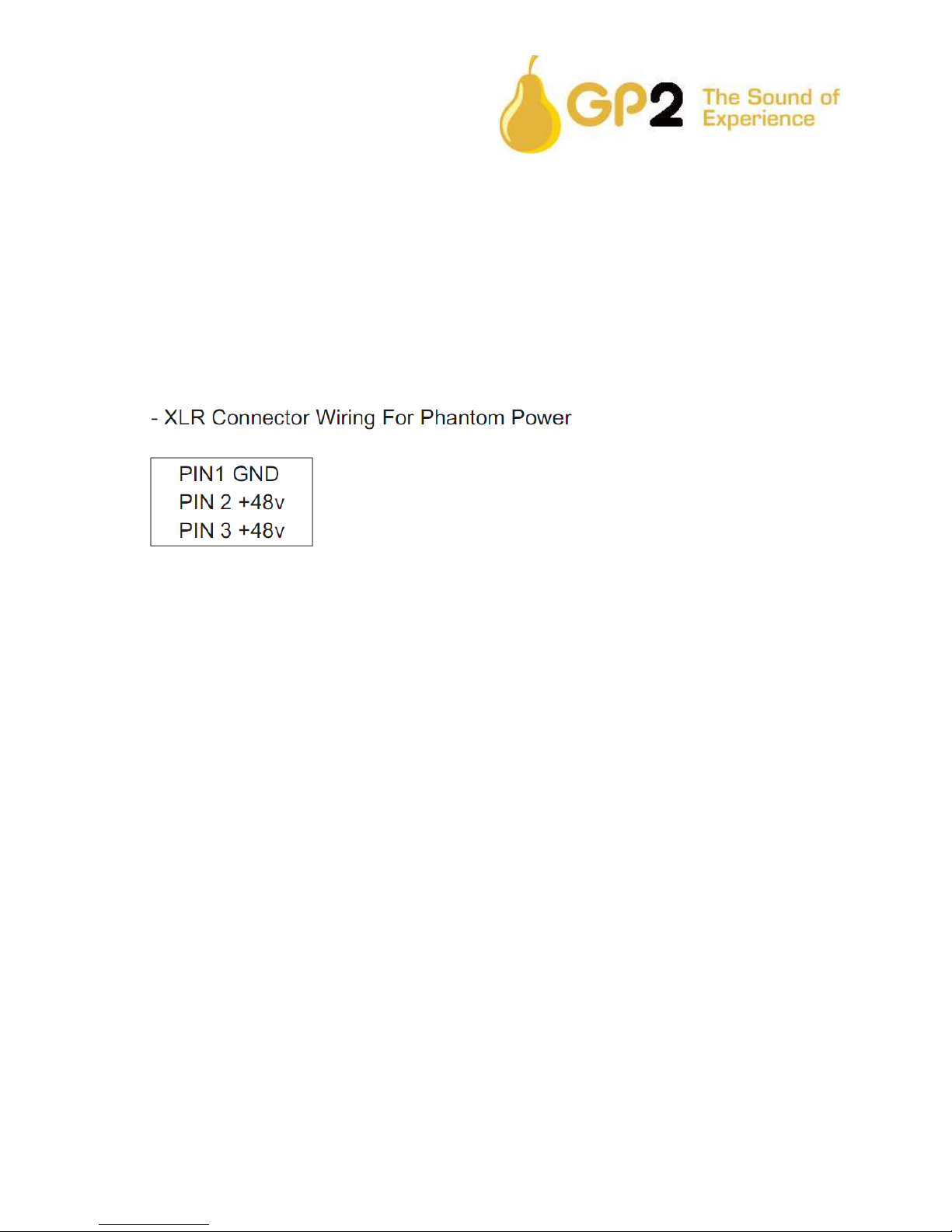
Phantom Power
Phantom power may be applied to the microphone socket by depressing the + 48V switch. Do
not attempt to connect any microphone that does not require phantom power, or any other
equipment to an input socket that has phantom power switched on as damage may result.
Selecting Phantom Power to this input will require pushing the +48V Switch in to enable
Phantom power on that particular channel. +48V Switch will illuminate to indicate Phantom Power is
selected.
CAUTION: Never switch phantom power on or off or plug /unplug A microphone with
phantom power applied unless the output level Control is turned down. Failure to do so may
result in a thump in your monitor or loudspeakers or PA system.
Input Gain
The gain of the preamp stage is variable from +11 to 26. This is a very wide range to cater for
all types of microphone and recording situations, but care must be taken not to apply large
sudden changes in gain which may result in unexpectedly large output signals. It is quite normal
to have to apply larger amounts of gain for less sensitive microphones, such as dynamic types
and similarly apply much less input gain for high output condenser microphones.
Drive and Peak Lamps
The white lamp provides a visual indication of the signal level. The drive lamp will gradually
illuminate as the input level or gain is increased over the range.
Email: mail@gp2inc.com Web: www.gp2inc.com
GP2 INC, BURLINGTON, ONTARIO CANADA

Phase Reverse
The phase reverse switch allows correction of a phase error, which may have occurred in
microphone wiring or placement. Phase errors can be due to two microphones picking up the
same signal at the same time. If an error is suspected it is a simple operation to check by
phase reversing each channel in turn.
Instrument Input
On each channel there is a front panel combination XLR and 0.25” instrument jack connector.
This is for connecting low level instruments such as electric guitars, The instrument input
eliminates the need for an external DI box since the high impedance instrument input will
convert the signal to a high quality balanced or unbalanced output .
Connecting an instrument to this input will require pushing the Line/Mic. Switch in to disable
the microphone input on that particular channel. The Line/Mic. Switch will illuminate to indicate
Line is selected.
When using the line input function, the Phantom power, Phase and Pad switches will have no
effect on the channel switched for Line use. These switches effect the Microphone selection only.
Email: mail@gp2inc.com Web: www.gp2inc.com
GP2 INC, BURLINGTON, ONTARIO CANADA

5. BLOCK DIAGRAM
Email: mail@gp2inc.com Web: www.gp2inc.com
GP2 INC, BURLINGTON, ONTARIO CANADA

6. GETTING STARTED
1) Combination Microphone/Instrument Front Panel Input.
2) Microphone/Line Select Switch. Out for Microphone Input in (Illuminated) for line in.
3) Phantom Power (48V) Select Switch. Out For No Phantom Power in (Illuminated) For 48V.
4) Phase reverse Select Switch. Out for No Reverse In (Illuminated) For Reverse.
5) Pad Select Switch. Out For No Pad in (Illuminated) For -20 DB Pad.
6) Gain Control Knob Clockwise for more Gain
7) Power Indicator Illuminated When Power Is On.
8) Level Indicator.
9) AC Main Input.
10) On / Off Switch
11) Fuse Drawer ( Replace fuse only with the same Type And Rating )
12) Voltage Switch Jumper With Indicator (115/230V)
13) Rear Panel Microphone Input
14) Rear Panel Microphone Output
GP2 INC, BURLINGTON, ONTARIO CANADA
Email: mail@gp2inc.com Web: www.gp2inc.com

7. SPECIFICATIONS
Highlights:
• JT-11 DM Input Transformer per Channel.
• JT-110 K output put Transformer per Channel.
• JT-DB-E DIRECT INPUT Transformer per Channel. (When Line Selected)
• Contains one 990 Discrete Op-Amps per Channel. Faster, quieter, more powerful and better
sounding than typical monolithic op-amps.
Standard Features:
• 20 position detent Gain Control.
• 20dB PAD switch for XLR Microphone inputs.
• Line Microphone select switch.
• Polarity Reverse switch for XLR Microphone inputs.
• Phantom Power switch for XLR Microphone inputs.
• All (16) Front Panel Switches Are LED Illuminated.
• Gold Plated Connectors throughout entire circuit for maximum reliability.
• Incandescent lamp, for monitoring preamp output.
• Thermally protected Toroidal Power Transformer with Additional Shielding. Eliminates hum
problems so no external power supply is needed.
• Power Input Module Allows Voltage Selection and Provides AC Line Filter.
Phantom Power
Voltage +48 VDC Current (maximum) 9.5 mA
Power Requirements,
4 Channels +15% 120, 240 VAC
120-240 ~ VOLT
300-150mA 60/50HZ
Dimensions: 1.75H x 19W x 14D Inches
(Suitable for rack mounting)
Email: mail@gp2inc.com Web: www.gp2inc.com
GP2 INC, BURLINGTON, ONTARIO CANADA

8. Warranty Card
The GP2QPA Pre-amp is supported by a lifetime warranty for faults or defective
Materials or workmanship during production.
Simply return your GP2QPA Pre-amp to the manufacturer following the instructions
On the website. WWWgp2inc.com
Your GP2QPA will be inspected and if found to qualify for the warranty will be replaced
Ore repaired with shipping costs refunded.
The warranty excludes damage caused by deliberate or accidental misuse, operation on the incorrect
mains voltage or without the correct type and valve of fuse fitted. It is the user’s responsibility to ensure
Fitness for purpose in any particular application. The warranty is limited to repair or replacement.
Warranty will be void if the unit has been opened. All units are serialized and must have the tag intact
on the machine.
For all other repairs a cost estimate will be supplied before the repair is completed.
FOR YOUR REFERENCE
MODEL # ____ __________________________________
SERIAL # _______
DATE OF PURCHASE
DELIVERY _________________________________
Signature __________
Email: mail@gp2inc.com Web: www.gp2inc.com
GP2 INC, BURLINGTON, ONTARIO CANADA
 Loading...