

Page 1
MW
8
Owner’s Manual
• Installation
• Use
• Maintenance
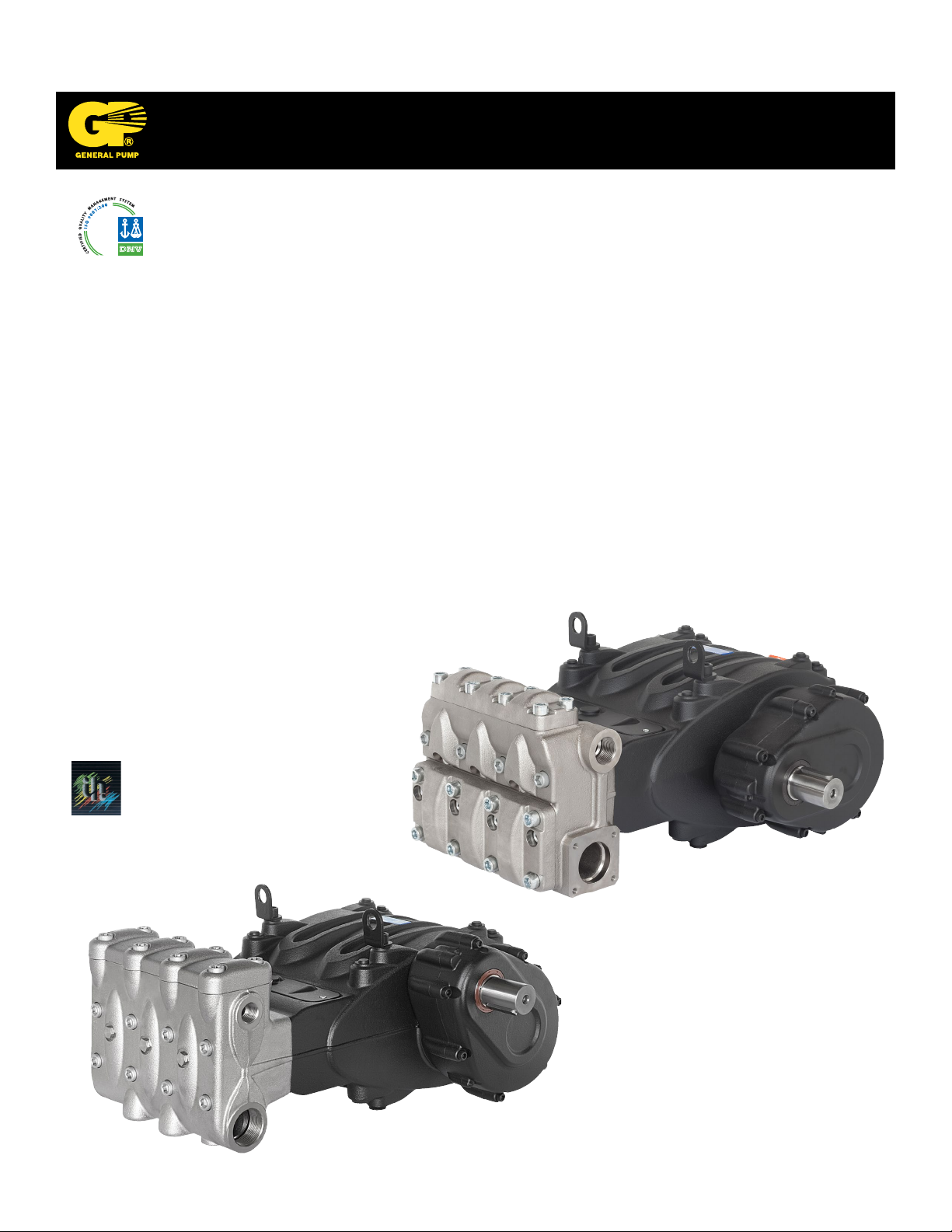
General Pump
is a member of
the Interpump Group
MW32A-MWS36A-MWS40A
MWS45A-MWS50A-MWS55A
Ref 300790 Rev. H
03-18
Page 2

GENERAL PUMP
INDEX
1. INTRODUCTION ............................................................... Page 4
2. DESCRIPTION OF SYMBOLS ....................................................Page 4
3. SAFETY ...................................................................... Page 5
3.1 General safety instructions ....................................................Page 5
3.2 High pressure unit safety requirements ........................................... Page 5
3.3 Safety during operation ....................................................... Page 5
3.4 General procedures for using nozzles ............................................ Page 5
3.5 Safety during unit maintenance .................................................Page 6
4. PUMP IDENTIFICATION ......................................................... Page 6
5. TECHNICAL CHARACTERISTICS ................................................. Page 7
6. DIMENSIONS AND WEIGHT .....................................................Page 8
7. OPERATING INSTRUCTIONS ....................................................Page 9
7.1 Water temperature ........................................................... Page 9
7.2 Maximum flow and pressure rates ............................................... Page 9
7.3 Minimum RPM ..............................................................Page 9
7.4 Recommended lubricant types and Manufacturers .................................. Page 9-10
A member of the Interpump Group
MW SERIES
8. PORTS AND CONNECTIONS ....................................................Page 11
9. PUMP INSTALLATION ..........................................................Page 12
9.1 Installation .................................................................Page 12
9.2 Direction of rotation .......................................................... Page 13
9.3 Version change and reducer positioning ..........................................Page 13
9.4 Hydraulic connections ........................................................Page 14
9.5 Pump power supply ..........................................................Page 14
9.6 Suction line ................................................................Page 15
9.7 Filtration ...................................................................Page 15
9.8 Outlet line .................................................................. Page 16
9.9 Internal diameter of hose ...................................................... Page 17
9.10 V-belt transmission .........................................................Page 18
10. START UP AND OPERATION .................................................... Page 18
10.1 Preliminary inspections ...................................................... Page 18
10.2 Starting up ................................................................ Page 19
11. PREVENTATIVE MAINTENANCE ................................................. Page 19
12. PUMP STORAGE .............................................................. Page 20
12.1 Filling the pump with anti-corrosion emulsion or anti-freeze .......................... Page 20
12.2 Hoses .................................................................... Page 20
13. PRECAUTIONS AGAINST FREEZING ..............................................Page 20
14. WARRANTY TERMS ............................................................Page 20
15 TROUBLESHOOTING ...........................................................Page 21
16. EXPLODED VIEWS AND PARTS .................................................. Page 22-25
Ref 300790 Rev. G
03-18
Page 2
Page 3

GENERAL PUMP
INDEX
17. SPECIAL VERSIONS ........................................................... Page 26
17.1 MWN Pump ............................................................... Page 26
17.1.1 Operating instrucions ....................................................Page 26
17.1.2 Water temperature ......................................................Page 26
17.1.3 Maximum pressure and flow rate ........................................... Page 26
17.1.4 Minimum RPM .........................................................Page 26
17.1.5 Technical characteristics ................................................. Page 26
17.1.6 Dimensions and weight ..................................................Page 27
17.1.7 Exploded view .........................................................Page 31
17.2 MWR Pump ............................................................... Page 32
17.2.1 Operating instrucions ....................................................Page 32
17.2.2 Water temperature ......................................................Page 32
17.2.3 Maximum pressure and flow rate ........................................... Page 32
17.2.4 Minimum RPM .........................................................Page 32
17.2.5 Technical characteristics ................................................. Page 32
17.2.6 Dimensions and weight ..................................................Page 33
17.2.7 Exploded view .........................................................Page 37
17.3 MWNR Pump .............................................................Page 38
17.3.1 Operating instrucions ....................................................Page 38
17.3.2 Water temperature ......................................................Page 38
17.3.3 Maximum pressure and flow rate ........................................... Page 38
17.3.4 Minimum RPM .........................................................Page 38
17.3.5 Technical characteristics ................................................. Page 38
17.3.6 Dimensions and weight ..................................................Page 39
17.3.7 Exploded view .........................................................Page 43
A member of the Interpump Group
MW SERIES
17.4 MWF Pump ............................................................... Page 44
17.4.1 Operating instrucions ....................................................Page 44
17.4.2 Water temperature ......................................................Page 44
17.4.3 Maximum pressure and flow rate ........................................... Page 44
17.4.4 Minimum RPM .........................................................Page 44
17.4.5 Technical characteristics ................................................. Page 44
17.4.6 Dimensions and weight ..................................................Page 44
17.4.7 Minimum Rotating Speed ................................................. Page 44
17.4.8 Flushing circuit diagram of use ............................................Page 45
18. REPAIR TOOLS ...............................................................Page 46
19. MAINTENANCE LOG ........................................................... Page 47
Ref 300790 Rev. G
03-18
Page 3
Page 4

GENERAL PUMP
A member of the Interpump Group
MW SERIES
1. INTRODUCTION
This manual describes the use and maintenance instructions of the MW pump, and should be carefully read and
understood before using the pump.
Correct use and adequate maintenance will guarantee the pumps trouble-free operation for a long time. General Pump
declines any responsibility for damage caused by misuse or the non-observance of the instructions indicated in this
manual.
Upon receiving the pump, check that it is complete and in perfect condition. Should anything be found out of order, please
contact us before installing and starting the pump.
2. SYMBOL DESCRIPTIONS
Warning
Potential Danger
Read carefully and understand
the manual before operating
the pump
Danger
High Voltage
Danger
Wear protective mask
Danger
Wear goggles
Danger
Wear protective gloves
Danger
Wear protective boots
Ref 300790 Rev. H
03-18
Page 4
Page 5
GENERAL PUMP
A member of the Interpump Group
MW SERIES
3. SAFETY
3.1 General Safety Indications
Improper use of pumps and high pressure systems, and the non-compliance with installation and maintenance
instructions may cause severe injury to people and/or damage to property. Anyone assembling or usinge high pressure
systems must possess the necessary competence to do so, should be aware of the characteristics of the components
assembled/used, and must take all precautions necessary to ensure maximum safety in any operating condition. In the
interest of safety, both for the Installer and the Operator, no reasonably applicable should be omitted.
3.2 High pressure unit safety requirements
1. The pressure line must always be equipped with a safety valve.
2. High pressure system components, in particular for those units working outside, must be adequately protected
against rain, frost and heat.
3. The electrical control system must be adequately protected from water spray, and must comply with the specific
regulations in force.
4. High pressure hoses must be properly sized for maximum operating pressure of the system and always and only
used within the operating pressure range specified by the hose manufacturer. The same rules should be observed
for all other auxiliary systems affected by high pressure.
5. The ends of high pressure hoses must be sheathed and secured to a solid structure to prevent dangerous
whiplash in case of bursting or broken connections.
6. Appropriate safety guards must be provided for the pump transmission systems (couplings, pulleys and belts,
auxiliary drives).
3.3 Safety During Operation
The working area of a high pressure system must be clearly marked. Access must be prohibited to un-authorized
personnel and, wherever possible, the area should restricted or fenced. The personnel authorized to access this area
should first be trained, and informed about the risks that may arise from failures or malfunctions of the high pressure unit.
Before starting the unit, the operator must check:
1. That the high pressure system is properly powered (see paragraph 9.5).
2. That pump intake filters are perfectly clean; we advise the use of a device that indicates the filters clogging level.
3. Electrical parts are adequately protected and in perfect condition.
4. The high pressure hoses do not show apparent signs of abrasion, and that fittings are in perfect shape.
Any fault or reasonable doubt that may arise before or during operation should be promptly reported and verified by
competent personnel. In these cases, pressure should immediately be released and the high pressure system stopped.
3.4 General Procedures For Using Nozzles
1. The Operator must always place his own and other worker’s safety before any other interest; his and should always
be governed by good sense and responsibility.
2. The Operator must always wear a helmet with a protective visor, waterproof clothing, and appropriate boots capable
of guaranteeing grip on wet pavement.
Ref 300790 Rev. H
03-18
Page 5
Page 6
GENERAL PUMP
Note: appropriate clothing will effectively protect against water spray, but it may not offer adequate protection against the
direct impact of water jets or sprays from a close distance. Some circumstances may require further protection.
3. It is generally best to organize personnel into teams of at least two people capable of giving mutual and immediate
assistance in case of necessity and of taking turns during long and demanding operation.
4. Access to the work area that is within the water jets’ range must be absolutely prohibited to and free from objects
that, inadvertently under a pressure jet, can be damaged and or create dangerous situations.
5. The water jet must only and always be directed in the direction of the work area, including during testing or
preliminary tests or checks..
6. The Operator must always pay attention to the trajectory of the debris removed by the water jet. If necessary, suitable guards must be provided by the Operator to protect anything that may be accidentally exposed.
7. The Operator should not be distracted for any reason during operation. Workers needing to access the operating
area must wait for the Operator to stop work, and then immediately make their presence known.
8. For safety reasons, it is important that each member of the team is fully aware of the intentions and actions of
other team members in order to avoid dangerous misunderstandings.
9. The high pressure system must not be started up and run under pressure without all team members in position
and without the Operator having already directed his/her lance toward the work area.
3.5 Safety During System Maintenance
1. The pressure system meintenance must be carried out in the time intervals set by the manufacturer who is
responsible for the whole group according to law.
2. Maintenance should always be carried out by trained and authorized personnel.
3. Assembly and disassembly of the pump and its various components must be performed exclusively by authorized personnel, using appropriate equipment in order to avoid damage to components and connections.
4. Always use original spare parts to ensure total reliability and safety.
A member of the Interpump Group
MW SERIES
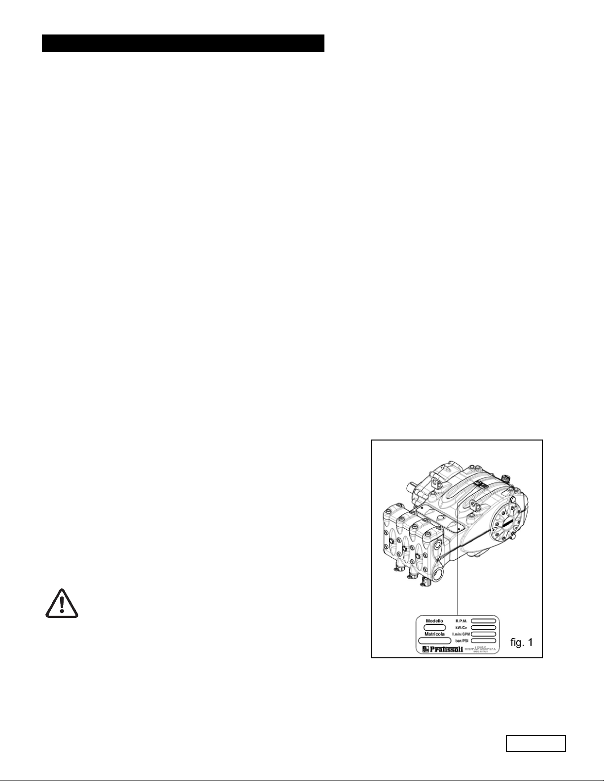
4. PUMP IDENTIFICATION
Each pump has a specific label which contains:
Pump model and version
Serial Number
Flow Rate - GPM
Pressure - PSI
Power - Hp-kW
Maximum RPM
Pump model, version and serial number must always
be specified when ordering spare parts.
Ref 300790 Rev. H
03-18
Page 6
Page 7

GENERAL PUMP
5. TECHNICAL FEATURES
A member of the Interpump Group
MW SERIES
MODEL RPM
MW32A 1500/1800/2200 36.0 136 4350 300 106 79
MWS36A 1500/1800/2200 45.5 172 3900 269 121 90
MWS40A 1500/1800/2200 56.0 213 3050 210 117 87
MWS45A 1500/1800/2200 71.0 269 2500 172 121 90
MWS50A 1500/1800/2200 87.5 333 2000 138 119 88
MWS55A 1500/1800/2200 105.5 400 1450 100 104 77.5
FLOW RATE PRESSURE POWER
GPM l/min PSI Bar Hp kW
Ref 300790 Rev. H
03-18
Page 7
Page 8
GENERAL PUMP
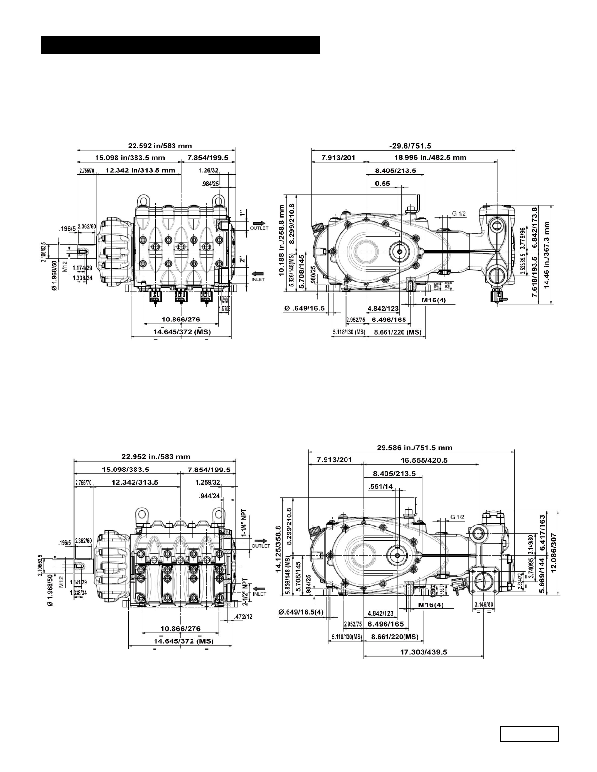
6. DIMENSIONS AND WEIGHT
For dimensions and weight of MW32A, MWS36A and MWS40A pumps, please refer to fig. 2.
A member of the Interpump Group
MW SERIES
Weight: 540 Lbs./244 Kg.
For dimensions and weight of MWS45A, MWS50A and MWS55A pumps, please refer to fig. 2a.
fig. 2
Weight: 540 Lbs./245 Kg.
fig. 2a
Ref 300790 Rev. H
03-18
Page 8
Page 9
GENERAL PUMP
A member of the Interpump Group
7.INFORMATION ABOUT PUMP USE
MW SERIES
The MW/S pump was designed to operate with filtered water (see paragraph 9.7) and at
maximum temperature of 104
Other fluids may be used only upon the approval of The Customer Service Department .
7.1 WaterTemperature
The max water temperature is 104
of up to 1400F (600C) for short periods of time. In this case we advise consulting the Customer Service
Department.
7.2 Max Flow Rate and Pressure Values
The performance values indicated in the catalog refer to the maximum performance of the pump. Regardless of the power
used, pressure and maximum RPM values indicated on the plate may not be exceeded unless expressly authorized by the
Customer Service Department.
7.3 Lowest RPM
Any RPM value different from what is indicated in the performance table (see chapter 5) must be expressly authorized by
the Customer Service Department.
7.4
Recommended Lubricant Oil Types & Manufacturers
The pump is delivered with lubricant oil compliant with room temperatures ranging between 32
300C ). Some recommended lubricant types are indicated in the table below; these lubricants are treated with additives
in order to increase corrosion protection and resistance to fatigue. As an alternative, Automotive SAE 85W-90 gearing
lubricants may also be used.
0
F (400 C).
0
F (400 C).However, it is possible to use the pump at temperatures
0
and 89.60 F (00 and
BRAND TYPE
GENERAL PUMP SERIES 220
ARAL Aral Degol BG220
BP ENERGOL HLP 220
CASTROL
ELF
ESSO NUTO 220
FINA Cirkan 220
FUCHS RENOLIN 220
MOBIL DTE OIL BB
SHELL TELLUS C 220
TEXACO RANDO HD 220
TOTAL CORTIS 220
Hyspin VG 220, Magna
POLYTELIS 220
220
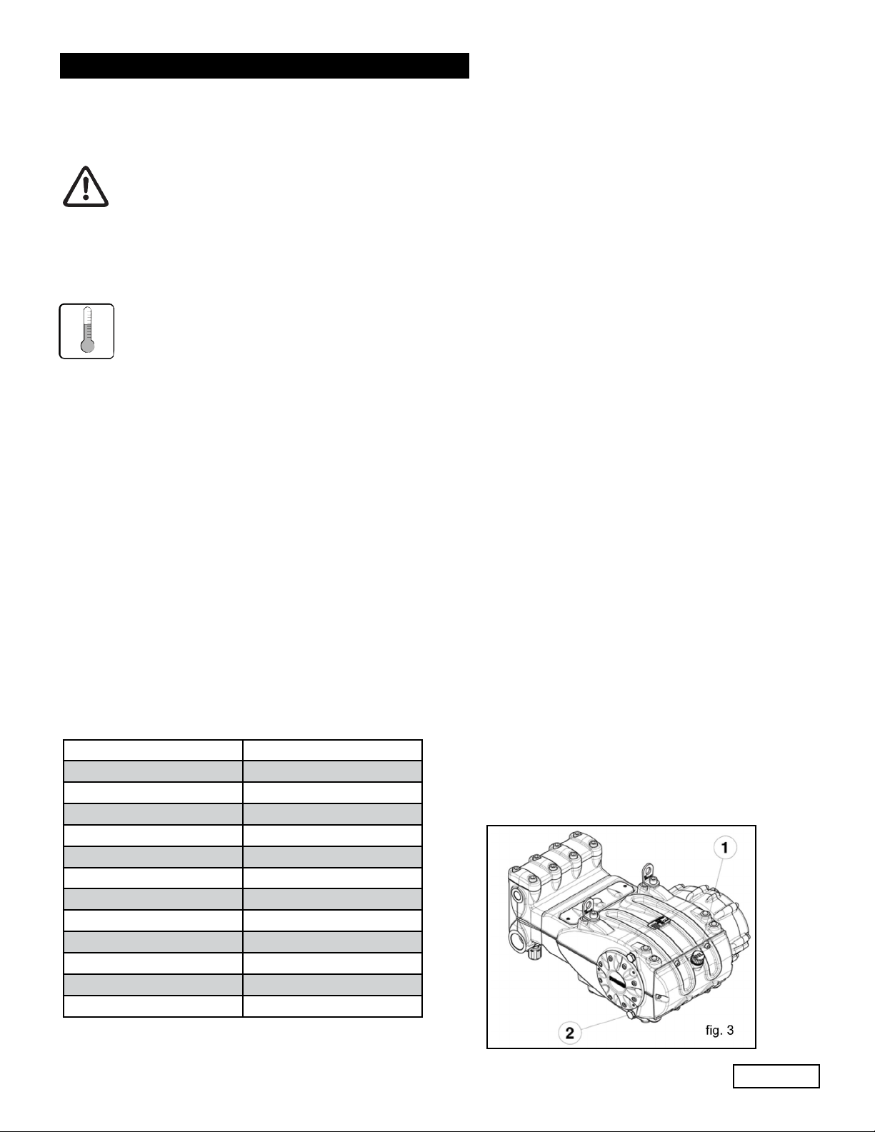
Check the oil level by using the oil level dipstick (1),
fig. 3. Refill if necessary to top off level. Correct oil level
inspection is done with the pump at room temperature;
oil is changed with the pump at working temperature, by
removing the rear plug (2), fig 3..
Checking and changing oil is to be carried out as indicated
in Chapter 11. The amount required is 304 oz. (9 liters).
Ref 300790 Rev. H
03-18
Page 9
Page 10
GENERAL PUMP
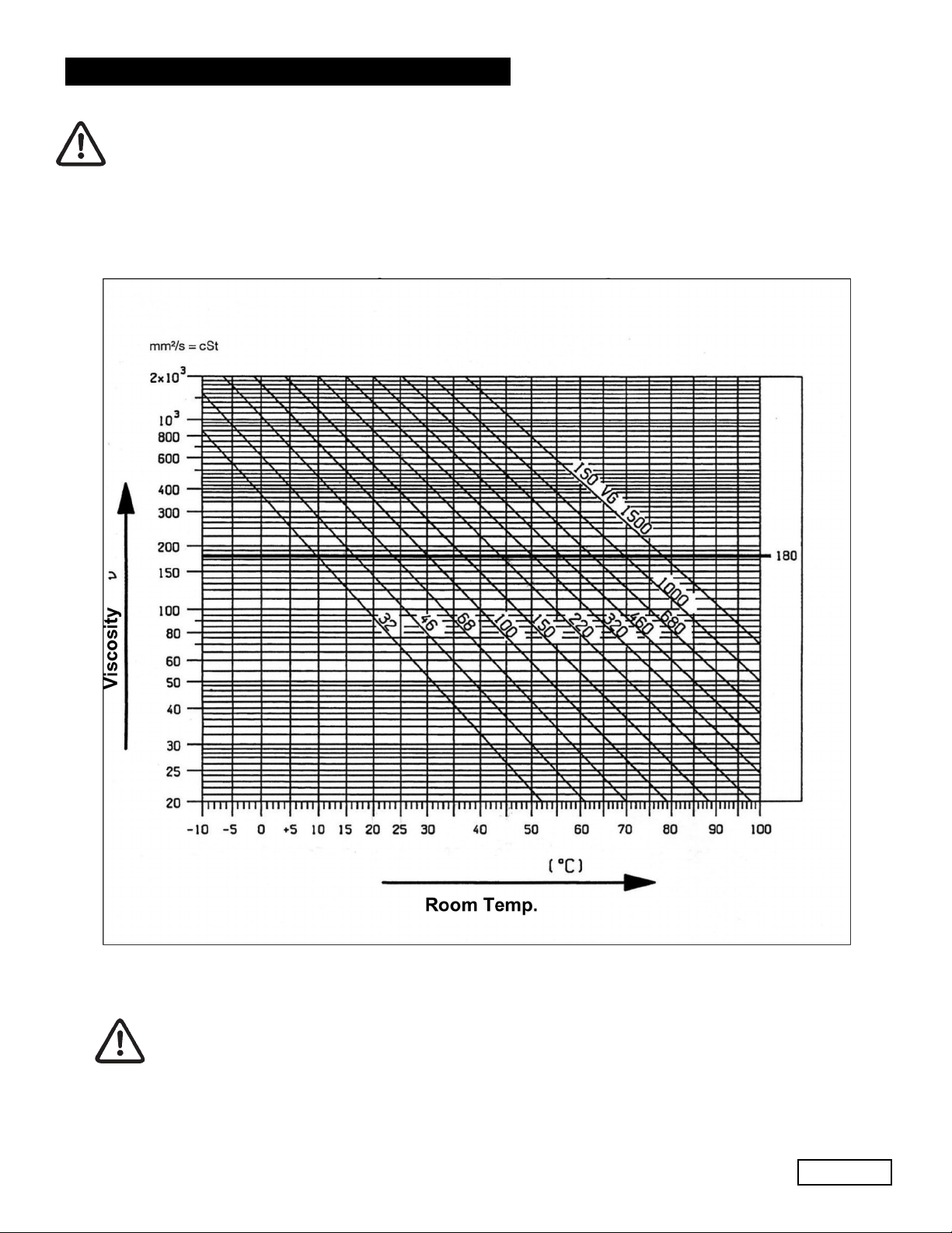
In any case, oil must be changed at least once a year since it may deteriorate by oxidation.
For room temperatures that differ from that mentioned earlier, follow the indications contained in the diagram
below, keeping in mind that the oil must have a minimum viscosity of 180 cSt.
A member of the Interpump Group
VISCOSITY/ROOM TEMPERATURE DIAGRAM
MW SERIES
Exhausted oil must be collected in an appropriate recipient and disposed of in appropriate
locations. In absolutely no case may it be dispersed into the environment.
Ref 300790 Rev. H
Page 10
03-18
Page 11
GENERAL PUMP
A member of the Interpump Group
MW SERIES
8. PORTS AND CONNECTIONS
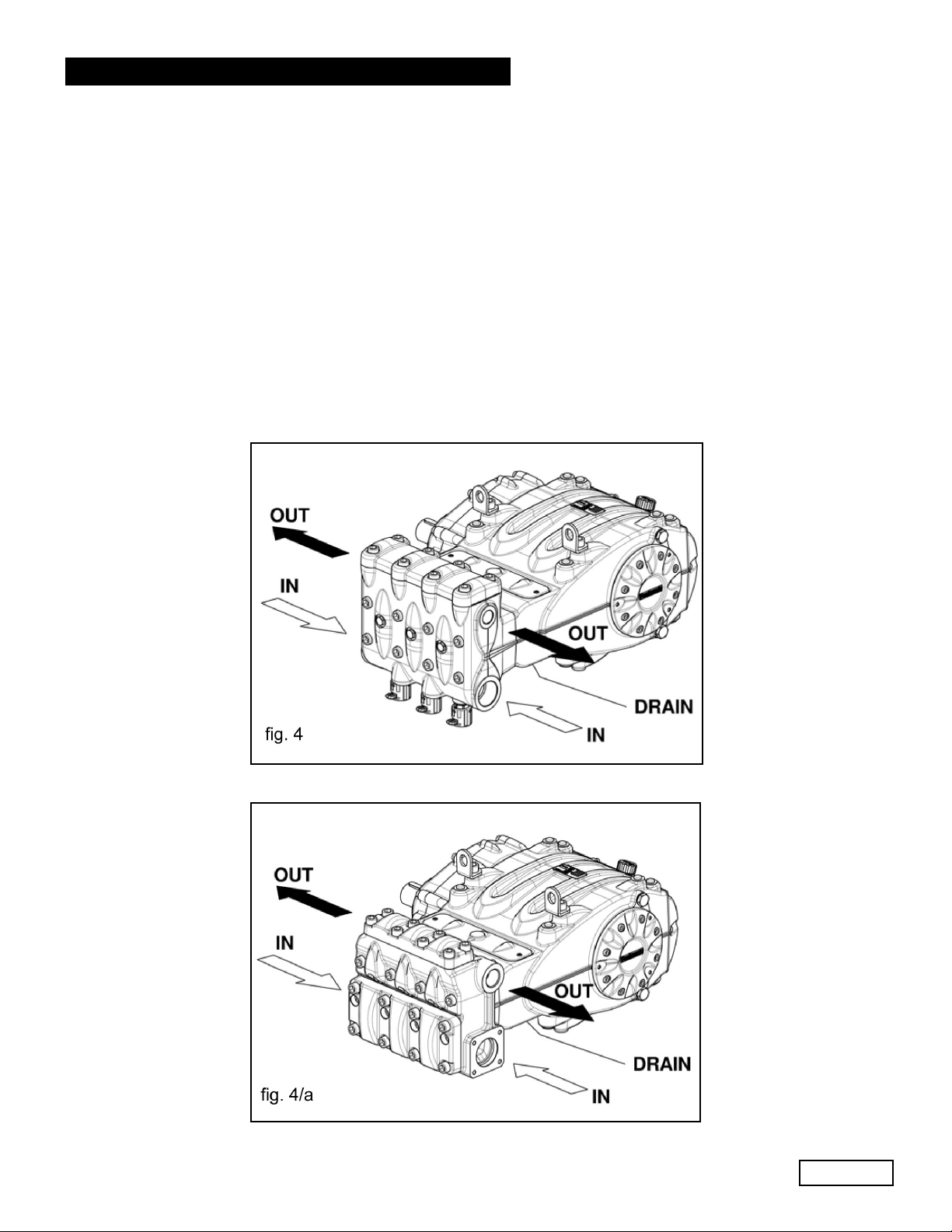
MW/S Series pumps are equipped with (see fig. 4 and 4a):
1. 2 inlet ports “IN”, 2” NPT (MW32A, MWS36A, MWS40A).
2 inlet ports “IN”, 2-1/2” NPT (MWS45A, MWS50A, MWS55A).
The line can be connected to either of the two inlet ports; the ones not being used must be hermetically sealed.
2. 2 outlet ports “OUT”, Ø 1” NPT-F (MW32A, MWS36A, MWS40A).
2 outlet ports “OUT”, Ø 1-1/4” NPT-F (MWS45A, MWS50A, MWS55A).
3. 1 drain port “DRAIN” with G1/2” hole in the lower cover to monitor any water leakage due to wear of the pressure
packings. In case of leaks, please consult the repair manual.
This hole must always be kept open.
Ref 300790 Rev. H
03-18
Page 11
Page 12
GENERAL PUMP
A member of the Interpump Group
MW SERIES
9. PUMP INSTALLATION
9.1 Installation
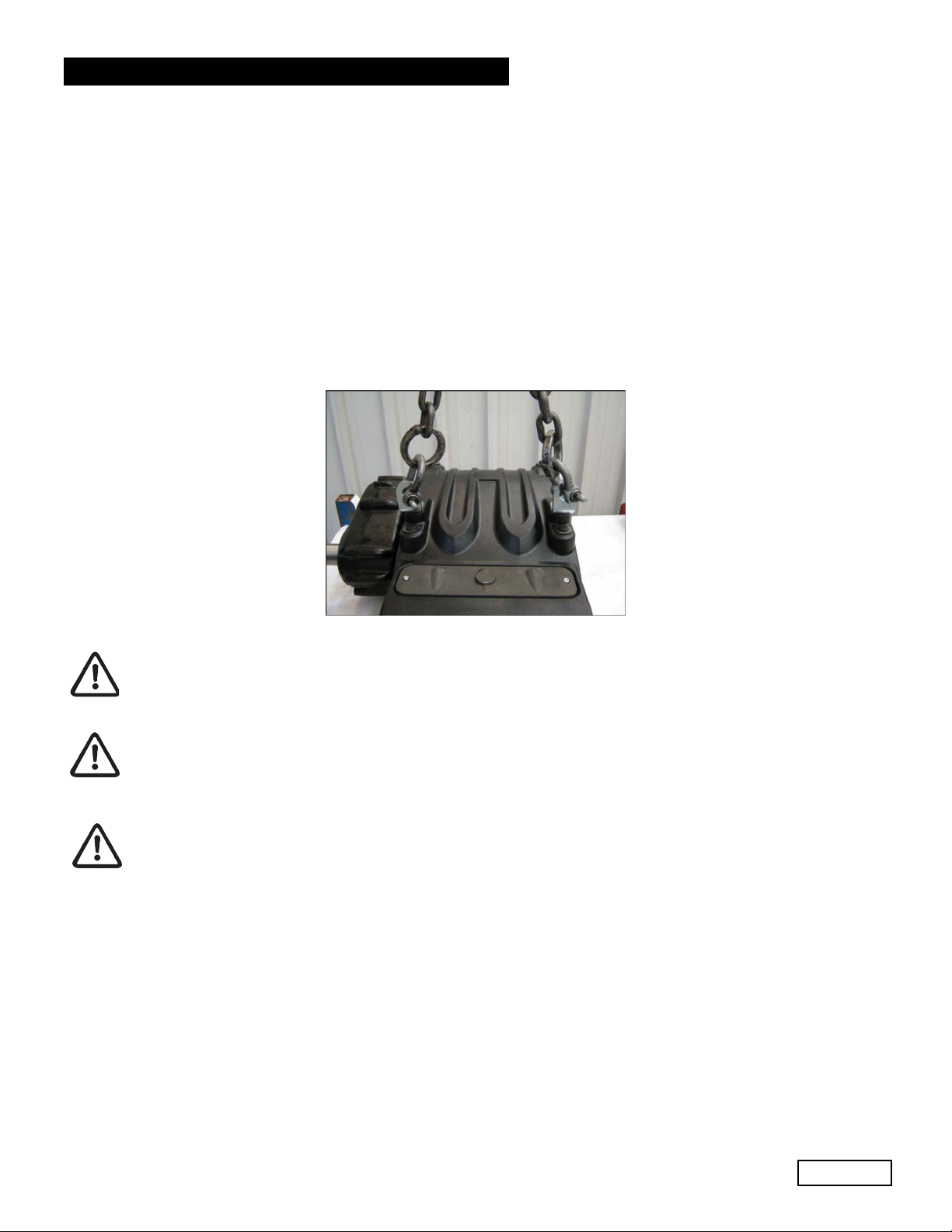
The pump must be installed in a horizontal position using the M16 threaded support feet.
Tighten the screws with a torque of 200 Nm (147.5 Ft-Lb)
The base must be perfectly flat and rigid enough as not to allow bending or misalignment on the pump coupling and
axis/transmission due to torque transmitted during operation.
Two lifting brackets are mounted on the pump for easy installation, as per the figure below.
The brackets are sized soley for pump lifting and therefore are absolutely not permitted for use
of additional loads.
Replace the oil filling hole closing service plug positioned on the rear casing cover with the
plug with oil dipstick. Check the correct quantity.
The dipstick must always be reachable, even when the unit is assembled.
The pump’s shaft (PTO) must not be rigidly connected to the motor unit.
The following transmission types are suggested:
• Flexible joint
• Cardan Joint (please respect the maximum working angles indicated by the manufacturer)
• Belts; for correct application, please contact the Customer Service Department.
Ref 300790 Rev. H
03-18
Page 12
Page 13
GENERAL PUMP
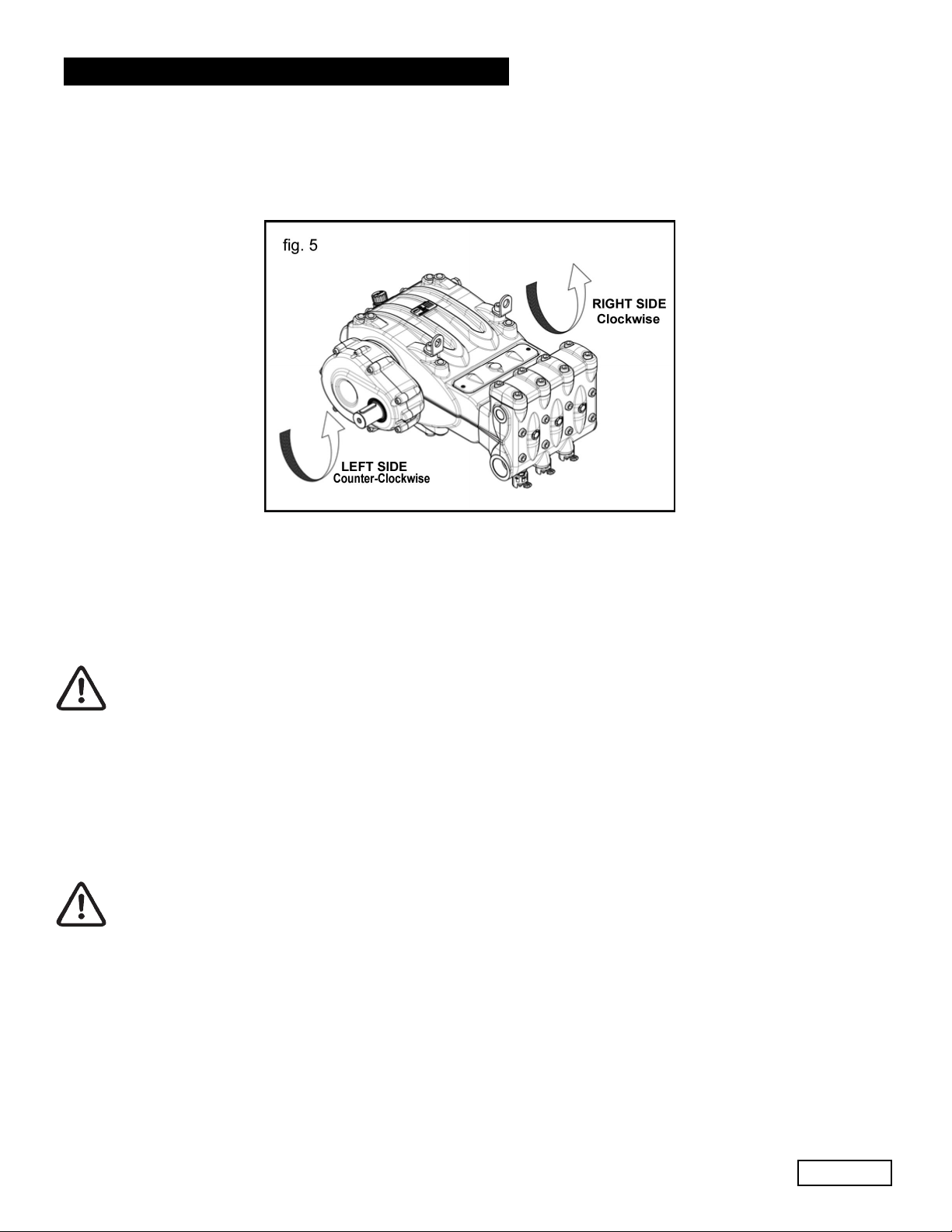
9.2 Direction of rotation
The PTO rotation is indicated by an arrow located on the reduction gear cover. From a position facing the pump head,
the rotation direction will be as in fig. 5.
A member of the Interpump Group
MW SERIES
9.3 Version Change and Reducer Positioning
A right version pump is defined when: observing the pump from the head side, the PTO shank of the pump shaft is on
the right side.
A left version pump is defined when: observing the pump from the head side, the PTO shank is on the left side.
See fig. 5.
The version may be changed only by trained and authorized personnel by carefully
following the instructions in the repair manual.
1. Separate the pump head from the power end (crankcase) as indicated in Chapter 2 in points 2.2.1 and 2.2.3 of the
Repair Manual.
2. Turn the power end (crankcase) 180
turned upward. Reposition the lifting bracket and relative hole closing plugs in the upper part of the casing. Invert
the two inspection covers, ensuring that the open one is positioned lower. Finally, properly reposition the
specification label in its housing on the casing.
Make sure that the lower inspection cover draining holes are open.
3. Reassemble the pump head with the power end (crankcase( as indicated in Chapter 2 in points 2.2.1 and 2.2.4 of
the Repair Manual.
o
and reposition the rear casing cover in such a way that the oil dipstick is
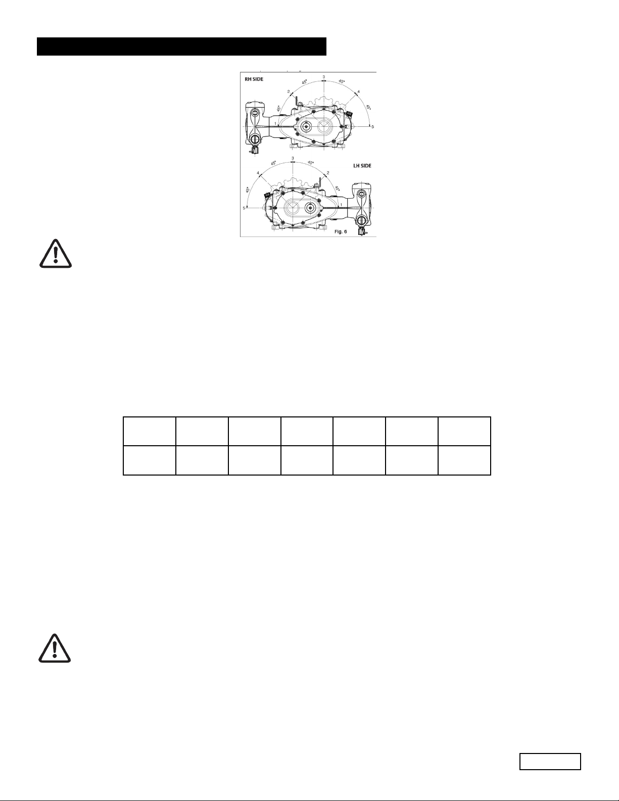
It is also possible to place the reduction gear in 5 different positions as per fig. 6.
Ref 300790 Rev. H
03-18
Page 13
Page 14
GENERAL PUMP
The reducer’s position may be changed only by trained and authorized personnel by carefully following
the instructions in the repair manual.
9.4 Hydraulic Connections
In order to isolate the system from the vibrations produced by the pump, we advise to build the first section of the duct
near the pump (both for intake and delivery) with flexible hose. The consistency of the intake section must allow to avoid
deformation caused by the depressurization produced by the pump.
A member of the Interpump Group
MW SERIES
fig. 6
9.5 Pump Power Supply
MW/S pumps must always be installed under positive head, i.e. they must receive water by gravity or by forced feeding,
and never suctioned from a lower level. The pumps can tolerate minimum NPSH even as low as 1 m. (3.28 ft.), however, to obtain a better volumetric efficiency and above all to avoid cavitation, the minimum NPSH available, measured at
the pump inlet flange, will have to be at least equal or higher than the values shown in the chart below.
MW32A MWS36A MWS450A MWS45A MWS50A MWS55A
NPSHr (ft) 4.5 5.5 6.5 7.5 8 9
For higher cylinder capacity pumps (MWS45A-S50A-S55A), it is strongly recommended to use a booster pump to avoid
cavitation, in view of the geometry on the hydraulic section and of the remarkably high flow rates.
The booster pump must have the following specifications: flow rate at least double the rated flow rate of the pump, and
pressure between 30 to 40 PSI (2 to 3 Bar). These feeding conditions must be respected at any operating RPM.
Booster start-up must always precede plunger pump start-up. In order to protect the pump, we advise to
install a pressure switch on the feeding line after the filters.
Ref 300790 Rev. H
03-18
Page 14
Page 15
GENERAL PUMP
9.6 Suction Line
For the pump’s correct operation, the suction line must have the following characteristics:
1. Minimum internal diameter as indicated in the diagram in paragraph 9.9, and in any case equal or greater than
the pump head’s value. Along the duct, avoid localized diameter reductions that may cause pressure drops with
subsequent cavitation. Absolutely avoid 900 elbows, connections with other hoses, bottlenecks, counter-slopes,
upside down “U” shaped curves, “T” connections.
2. With a layout that is set in such a way to prevent cavitation.
3. It should be perfectly airtight, and built in a way that guarantees perfect sealing over time.
4. Avoid pump emptying when stopping (even partial emptying).
5. Do not use hydraulic fittings, 3 or 4 way fittings, adapters, etc., since they may hinder the pump’s performance.
6. Do not install Venturi tubes or injectors for detergent intake.
7. Avoid the use of standing valves, check valves, or any other type of one-way valves.
8. Do not connect the by-pass line from the valve directly to the pump suction line.
9. Provide appropriate baffle plates inside the tank in order to avoid water flows coming from both the by-pass and
feeding which lines may create turbulance near the tank’s outlet port.
10. Make sure that the suction line is perfectly clean inside before connecting it to the pump.
11. The pressure gauge for checking booster pressure must be installed near the plunger pump’s inlet port, and always
downstream from the filters.
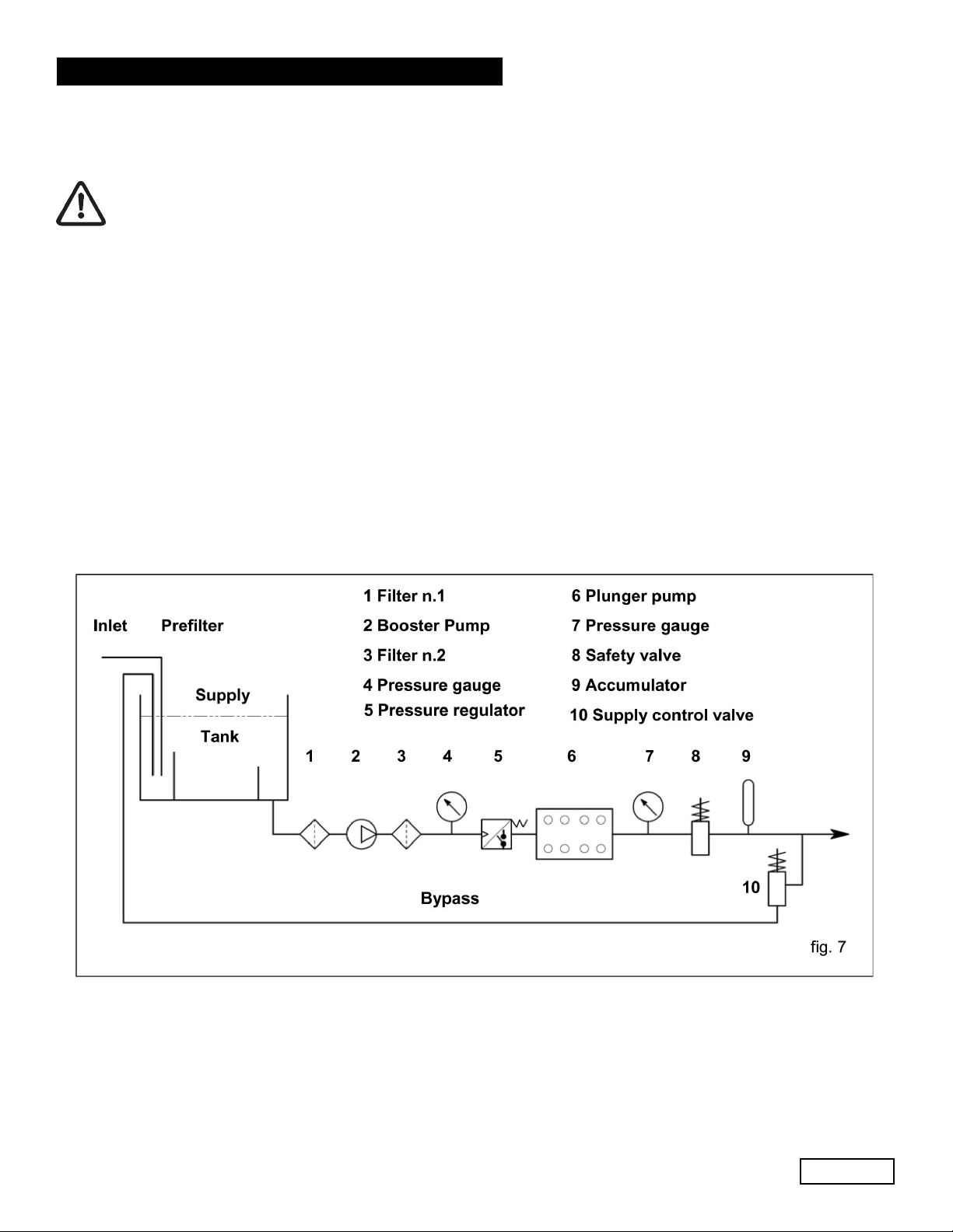
9.7 Filtering
On the suction line, install two filters as indicated in fig. 7 and fig. 7/a.
A member of the Interpump Group
MW SERIES
With the manual adjustment valve:
Ref 300790 Rev. H
03-18
Page 15
Page 16

GENERAL PUMP
With the pneumatic adjustment valve:
A member of the Interpump Group
MW SERIES
The filter must be installed as close as possible to the pump, should allow easy inspection and have the following
characteristics:
1. Minimum capacity 3 times greater than the pump’s rated flow value.
2. Filter port diameters must not be smaller than the pump inlet ports.
3. Filtration degree ranging between 200 and 360 µm.
In order to guarantee correct pump operation, it is important to plan periodical cleaning of the filter
depending on actual pump usage, water quality and actual clogging conditions.
9.8 Outlet Line
To obtain a correct delivery line, please comply with the following installation instructions:
1. The internal diameter of the hose must allow to guarantee correct fluid speed; see digram in paragraph 9.9
2. The first section of the hose connected to the pump must be flexible in order to isolate pump vibrations
from the rest of the system.
3. Use high pressure hoses and fittings that guarantee wide safety margins in any working condition.
4. Install a safety valve on the delivery line.
5. Use pressure switches suitable for the pulsating loads typical of plunger pumps.
6. In the design phase, take into proper account the pressure drop along the line, since this causes a reduction in
usage pressure with respect to the value measured at the pump.
7. If the pump pulsations are harmful for particular applications, install an appropriately sized pulsation dampener on
the outlet line.
Ref 300790 Rev. H
03-18
Page 16
Page 17

GENERAL PUMP
9.9 Internal Diameter of the Hose Line
To determine the internal diameter of the hose, please refer to the following diagram.
Suction Hose
With a flow rate of ~105 GPM (400 l/mn) and water speed of 1 m/sec. the diagram line that connects the two scales
intersects the central scale, indicating the diameters, at a value of ~ 3.5 inch (90 mm).
Delivery Hose
With a flow rate of ~105 GPM (400 l/mn) and water speed of 5.5 m/sec. The diagram line that connects the two scales
intersects the central scale, indicating the diameters at a value of ~ 1.6 inch (40 mm).
Optimal speed to be obtained with the booster pump:
• Suction: ≤ 1 m/sec.
• Delivery: ≤ 5.5 m/sec.
A member of the Interpump Group
MW SERIES
The diagram does not take into account the hose and valve resistance, the pressure drop due to the pipe length,
the viscosity and the temperature of the pumped fluid. If necessary, contact our Customer Service Department.
Ref 300790 Rev. H
03-18
Page 17
Page 18

GENERAL PUMP
9.10 V-belt Transmission
As indicated in paragraph 9.1, only in exceptional cases may the pump be driven by a v-belt system. For correct lay-out
sizing, please contact our Customer Service Department.
A member of the Interpump Group
MW SERIES
10. START-UP AND OPERATION
10.1 Preliminary Inspections
Before Start-up Be sure that:
The suction line is connected and up to pressure (see Chapter 9) the pump must never run dry.
1. The suction line must be perfectly airtight.
2. All the On-Off valves between the pump and the feeding source are completely open. The delivery line must
discharge freely in order to allow the air in the pump to be expulsed easily, thus facilitating pump priming.
3. All suction/delivery connections and fittings must be correctly tightened.
4. Coupling tolerances on the pump/transmission axis (half-joint misalignment, Cardan inclination, belt
tightening, etc.) must remain within the limits indicated by the transmission Manufacturer.
5. The pump’s oil level must be verified using the correct dipsticks (position 1, fig 8).
In case the pump has not run for a long period of time, recover the correct operation of the suction valves
by opening the three valve-lifting devices (see position 2, fig. 9). Be sure to reclose the valves before the
pump start-up. See fig. 10 for “work” and “rest” positions.
fig. 10
Ref 300790 Rev. H
03-18
Page 18
Page 19

GENERAL PUMP
10.2 Start-up
1. When starting the pump for the first time, check for the correct direction of rotation.
2. The pump must be started off-load.
3. Verify correct feeding pressure.
4. During operation, check that the rotating speed does not exceed the rated value.
5. Before putting the pump under pressure let it run for at least 3 minutes.
6. Before stopping the pump, release the pressure by acting on the adjustment valve or on any discharging device.
Whenever priming problems arise due to insufficient feeding, intervene by removing the three front plugs
on the head (see position 3, fig. 11 and 11a).
A member of the Interpump Group
MW SERIES
11. PREVENTIVE MAINTENANCE
To guarantee pump reliability and efficiency, comply with the maintenance intervals as indicated in the table below.
PREVENTIVE MAINTENANCE
EVERY 500 HOURS EVERY 1000 HOURS
Check oil level Change oil
Check / Replace:*
• Valves
• Valve seats
• Valve springs
• Valve guides
Check / Replace:
• H.P packings
• L.P. packings
* For replacement follow instructions contained in the repair manual.
Ref 300790 Rev. H
03-18
Page 19
Page 20

GENERAL PUMP
12.
PUMP STORAGE
12.1 Filling the Pump With An Anti-Corrosion Emulsion or Anit-freeze By Using An External Diaphragm Pump
As In The Layout Shown in Paragraph 9.7.
a) Close the filter draining, if open.
b) Be sure that the connecting hose is clean, spread with grease and connect it to the high pressure outlet port.
c) Fit a suction hose to the membrane pump. Open the pump suction connection and fit hose between it and the
membrane pump.
d) Fill the container with the solution/emulsion.
e) Put the free extremeties of the suction line and the high pressure outlet hose inside the container.
f) Start up the diphragm pump.
g) Pump the emulsion until it comes out of the high pressure hose.
h) Continue pumping for at least another minute; if needed, the emulsion can be reinforced by adding, for example,
Shell Donax
i) Stop the pump, remove the hose from the suction connection and close it with a plug.
j) Remove the hose from the high pressure outlet port. Clean, grease and plug both connections and the
hoses.
12.2 Hoses
a) Before greasing and protecting the hoses according to the previously described procedure, dry the connections
using compressed air.
b) Cover with polyethelene.
c) Do not wrap them too tightly; be sure there is no bending.
A member of the Interpump Group
MW SERIES
13.
PRECAUTIONS AGAINST FREEZING
In areas and periods of the year where there is risk of freezing, follow the instructions indicated in Chapter 12
(see paragraph 12.1).
In the presence of ice, in no case must the pump be started until the entire circuit has been completely
thawed out; not complying with this indication may cause serious damage to the pump.
14.
WARRANTY TERMS
The pump is guaranteed for a period of 5 years from the delivery date, with the exception of parts subject to wear. In
any case, please refer to the contract terms for other warranty conditions. The warranty is void if:
a) The pump has been used for purposes that differ from that agreed.
b) The pump has been fit with an electric or diesel engine with performance greater than that indicated in the table.
c) The required safety devices were un-adjusted or disconnected.
d) The pump was used with accessories or spare parts not supplied by General Pump.
e) Damage was caused by:
1) improper use
2) the non-observance of maintenance instructions
3) use not compliant with operating instructions
4) insufficient flow rate
5) faulty installation
6) incorrect positioning or sizing of the hoses
7) non-authorized design changes
8) cavitation
Ref 300790 Rev. H
03-18
Page 20
Page 21

GENERAL PUMP
15.
TROUBLESHOOTING
The pump does not produce any noise at start-up:
• The pump is not primed and is running dry
• There is no water in the inlet line
• The valves are blocked
• The delivery line is closed and does not allow the air in the pump to be discharged
The pump pulses irregularly (knocking):
• Air suction
• Insufficient feeding
• Bends, elbows, fittings along the suction line obstruct the fluid’s passage
• The inlet filter is dirty or too small
• The booster pump, where provided, supplies insufficient pressure or flow rate
• The pump is not primed due to insufficient head or the delivery line is closed during priming
• The pump is not primed due to valve seizing
• Worn valves
• Worn pressure packings
• Incorrect operation of the pressure adjustment valve
• Transmission problems
The pump does not deliver the rated flow / is noisy:
• Insufficient feeding (see the causes listed above)
• RPM are less than the rated flow
• Excessive amount of water by-passed by the pressure adjustment valve
• Worn valves
• Leakage from the pressure packings
• Cavitation due to:
1) Wrong sizing of the suction hose/
undersized diameters
2) Insufficient flow rate
3) High water temperature
A member of the Interpump Group
MW SERIES
Insufficient pump pressure:
• The nozzle (or has become)too large
• Insufficient RPM
• Leakage from the pressure packings
• Incorrect operation of the pressure adjustment valve
• Worn valves
Overheated pump:
• The pump is overloaded (pressure or RPM exceed the rated values)
• Oil level is too low, or the oil is not of a suitable type, indicated in Chapter 7 (see paragraph 7.4)
• Incorrect alignment of the joint or pulleys
• Excessive inclination of the pump during operation
Pump vibrations or knocking:
• Air suction
• Incorrect operation of the pressure adjustment valve
• Valve malfunction
• Irregular drive transmission motion
Ref 300790 Rev. H
03-18
Page 21
Page 22

GENERAL PUMP
16. EXPLODED VIEW AND PARTS LIST
A member of the Interpump Group
MW32A/S36A/S40A SERIES
Ref 300790 Rev. H
03-18
Page 22
Page 23

GENERAL PUMP
Item Part # Description QTY.
1 F73120215 MANIFOLD-NPT 1
2 F10744401 DRAIN VALVE 3
3 F36208801 BALL VALVE ASSEMBLY 6
4 F36206766 INLET VALVE HOUSING 3
5 F90526000 ANTIEXTRUSION RING Ø51.5x56x1.5 3
6 F90389000 OR, Ø50.47X2.62 6
8 F36209051 INTERNAL VALVE GUIDE 6
9 F94760000 SPRING Ø 28.3X30.7 3
10 F36206105 INLET/OUTLET VALVE GUIDE 6
11 F36715101 INLET VALVE UNIT 3
12 F74210651 HP VALVE GUIDE SPACER
13 F73212270 OR, Ø 10.82X1.78 3
14 F90526500 ANTIEXTRUSION RING Ø 51.7X56.2X1.5 3
15 F36206966 OUTLET VALVE HOUSING 3
16 F90527600 ANTIEXTRUSION RING Ø 67.7X72.2X1.5 3
17 F90391100 OR, Ø 66.35X2.62 6
18 F94760500 SPRING Ø 28.5X32 3
19 F36715301 OUTLET VALVE UNIT 3
20 F74211070 HP OUTLET VALVE PLUG 3
21 F90528000 ANTIEXTRUSION RING Ø 67.7X72.2X1.5 3
22 F94775000 SPRING Ø 58X45.4 3
23 F74210866 OUTLET VALVE HOUSING RING 3
24 F99514700 SCREW, M16x180 8
25 F73210715 VALVE COVER 1
26 F99522200 SCREW, M16x180 8
27 F96710500 WASHER Ø 10X18X0.9, SS, PTFE 3
28 F99383000 SCREW, M10X140 3
F73040009 PLUNGER Ø 32 3
29
F73040109 PLUNGER Ø 36 3
F73040209 PLUNGER Ø 49 3
30 F90408500 O-RING, 49.21X3.53 3
31 901111 O-RING, 10.78X2.62 6
F73211656 PLUNGER LINER Ø 32 3
F73211756 PLUNGER LINER Ø 36 3
32
F73211856 PLUNGER LINER Ø 40 3
33 F90371000 OR, Ø 81X2 6
F73100092 PLUNGER HEAD RING Ø 32 3
34
F78100192 PLUNGER HEAD RING Ø 36 3
F74100092 PLUNGER HEAD RING Ø 40 3
F90278800 ALT. SEAL RING, Ø 32, HP 3
90282060 ALT. SEAL RING, Ø 36, HP 3
35
F90283200 ALT. SEAL RING, Ø 40, HP 3
F90278400 RESTOP RING Ø 32 3
90281800 RESTOP RING Ø 36 3
36
F90283800 RESTOP RING Ø 40 3
F73211068 SEAL SUPPORT, Ø 32 3
F73211168 SEAL SUPPORT, Ø 36 3
37
F73211268 SEAL SUPPORT, Ø 40 3
F90278000 ALT. SEAL RING, LP, Ø 32 3
38
F90279800 ALT. SEAL RING, LP, Ø 36 3
F90282800 ALT. SEAL RING,LP, Ø 40 3
41 F96735500 WASHER, Ø16X65X1 3
42 F73150022 CLOSED INSPECTION COVER 1
43 F73050336 PISTON GUIDE ROD 3
44 F90414800 OR, Ø 202.8X3.53 2
45 F73150122 OPEN INSPECTION COVER 1
46 F90168500 RAD. RING, Ø 40X72X7/8.5 3
47 99188400 SCREW, M6X20 3
48 F73120815 MANIFOLD FOR PISTON 1
F73050443 PISTON GUIDE 3
49
F73050543 PISTON GUIDE, +0.10 3
49A F73606201 PISTON GUIDE ASSEMBLY 3
50 F73210674 LIFTING BRACKET 2
51 F99513000 SCREW, M16x30, UNI 5931 4
52 F73030101 CONNECTING ROD ASSY. 3
53 F99378800 CONNECTING ROD SCREW 6
F90928300 CONROD HEAD SEMI-BUSHING, LOWER 3
55
F90928400 CONROD HEAD SEMI-BUSHING, LOWER, +0.25 3
F90928500 CONROD HEAD SEMI-BUSHING, LOWER, +0.50 3
REPAIR KITS
KIT
NUMBER
Positions
Included
F2136 (MW32A)
Plunger Packing Kit
30, 31, 33,
35, 36, 38,
F2137 (MWS36A)
Plunger Packing Kit
30, 31, 33,
35, 36, 38,
A member of the Interpump Group
F2138 (MWS40A)
Plunger Packing Kit
30, 31, 33,
35, 36, 38,
F2055
Valve Kit
11, 12,
19, 21
F2144 (MW32A)
Complete Seals Kit
5, 6, 14, 16, 17,
21, 30, 31, 33, 35,
36, 38, 44, 46, 64,
73, 83, 86, 101
MW32A/S36A/40A SERIES
Item Part # Description QTY.
F90928000 CONROD HEAD SEMI-BUSHING, UPPER 3
56
F90928100 CONROD HEAD SEMI-BUSHING, UPPER, +0.25 3
F90928200 CONROD HEAD SEMI-BUSHING, UPPER, +0.50 3
57 F90915800 CONROD FOOT BUSHING 3
58 F90069000 STOP RING, Ø 32, UNI 7437 6
59 F97744000 SPINDLE 3
60 99183700 SCREW, M6x14, UNI 5931 4
61 F73200064 FOOT 2
62 98206000 HOLE PLUG. Ø 15, TTN18 6
3
63 F98233500 OIL FILLING PLUG, G1” WITH ROD 1
64 90361600 OR, Ø 34.65X1.78 1
65 F73210295 TUBE FOR OIL FILLING PLUG, G1” 1
66 F91854000 CYL. ROLLER BEARING 1
F10076735 PINION, Z24 R1.875, HELICOL 1
F10076835 PINION, Z21 R2.238, HELICOL 1
67
F10076935 PINION, Z18 R2.722, HELICOL 1
F10082255 PINION, Z19 R3.211, HELICOL 1
68 F97623000 TMP. CYL. PIN. Ø 10X24, UNI 6364 2
69 F90101000 STOP RING, Ø 120, UNI 7437 1
70 F91859900 ADJUST ROLLER BEARING 11
71 F73210455 BEARING SUPPORT RING 1
72 F90081000 STOP RING, Ø 55, UNI 7435 1
73 F90172400 RAD. RING, Ø 55X75X8, VITON 1
74 F91500500 TAB, 14X9X60, UNI 6604 1
75 F73210589 RING GEAR SUPPORT RING 1
76 99366700 SCREW, M10X25, UNI 5739 2
77 F91511000 TAB, 22X14X80, UNI 6604 1
78 F74213255 RING GEAR STOP 1
79 F73020035 CRANKSHAFT C. 70 1
F10077035 RING GEAR, Z45 R1.875, HELICAL 1
F10077135 RING GEAR, Z47 R2.238, HELICAL 1
80
F10077235 RING GEAR, Z49 R2.722, HELICAL 1
F10082355 RING GEAR, Z61 R3.211, HELICOL 1
81 F99371000 SCREW, M10X40, UNI 5931 15
82 F73210113 REDUCTION GEAR COVER 1
83 F90415000 OR, Ø 253.6.X3.53 2
84 F73210013 REDUCTION GEAR BOX 1
85 F91881000 CYL ROLLER BEARING 2
86 F73210384 SIDE SEAL 2
87 F73010013 PUMP CASING 1
88 F73160022 CASING COVER 1
89 F99368600 SCREW, M10X30, UNI 5931 14
90 F73150222 BEARING COVER 1
91 F98218700 PLUG, G1/2”X13, SS 2
92 91751400 WASHER, Ø 21.5x27x1.5 2
100 98204600 PLUG, 1/4”X13 3
101 90358400 O-RING, Ø10.82X1.78 3
99 F73010113 PUMP CASING, FLUSHING 1
F10079455 PINION, Z18 R. 2.722 1
93
F10077355 PINION, Z24 R. 1.875 1
F10077455 PINION, Z21 R. 2.238 1
94 F73215513 HYDRAULIC GEAR COVER 1
89 F99368600 SCREW, M10X30, UNI 5931 8
95 F73150322 BEARING COVER, OPEN 1
96 F90391450 O-RING, Ø75.87X2.62 1
97 F73215654 RING 1
98 F90195000 RING, RAD., Ø90X110X12 1
39 F73215754 DRAIN 1
40 99367100 SCREW, M8X25 6
89 F99368600 SCREW, M10X30, UNI 5931 8
95 F73150322 BEARING COVER, OPEN 1
96 F90391450 O-RING, Ø75.87X2.62 1
98 F90195000 RING, RAD., Ø90X110X12 1
100 F73215754 PTO OUTLET 1
101 99367100 SCREW, M10X25 6
F2145 (MWS36A)
Complete Seals Kit
5, 6, 14, 16, 17,
21, 30, 31, 33, 35,
36, 38, 44, 46, 64,
73, 83, 86, 101
F2146 (MWS40A)
Complete Seals Kit
5, 6, 14, 16, 17,
21, 30, 31, 33, 35,
36, 38, 44, 46, 64,
73, 83, 86, 101
FLUSHING MANIFOLD
WITH HYDRAULIC MOTOR
DIRECT DRIVE
AUXILIARY PTO
F2150
Conn,Rod Kit
Conn. Rod Kit
55, 56 55, 56 55, 56
Ref 300790 Rev. H
F2151
+0.25
03-18
F2153
Conn. Rod Kit
+0.50
Page 23
Page 24

GENERAL PUMP
16. EXPLODED VIEW AND PARTS LIST
A member of the Interpump Group
MWS45-S50-S55 SERIES
Ref 300790 Rev. H
03-18
Page 24
Page 25

GENERAL PUMP
Item Part # Description QTY.
1 F73120315 MANIFOLD, NPT 1
2 F10744501 VALVE OPENING DEVICE 3
3 F96751400 WASHER, Ø 21.5X27X1.5 5
4 F98218500 STEEL PLUG, 1/2” 3
5 F36206666 INLET VALVE HOUSING 3
6 F90527000 ANTI-EXTRUSION RING, Ø 61.2X67X2 3
7 F90410500 OR, Ø 59.62X3.53 3
9 F36208701 BALL VALVE ASSY. 3
10 F36208951 INTERNAL VALVE GUIDE 3
11 F94769800 SPRING, Ø41.5X37.9
12 F36206005 INLET VALVE GUIDE 3
13 F36715001 INLET VALVE UNIT 3
14 F73210815 INLET VALVE COVER 1
F73040309 PLUNGER, Ø 45X117 3
F73040409 PLUNGER Ø 50X117 3
15
F73040509 PLUNGER Ø 55X117 3
16 F90414200 OR, Ø 85.32X3.53 3
17 F96710500 WASHER, Ø 10X18X0.9,SS, PTFE 3
18 F99383000 SCREW, M10X140 3
19 F99514200 SCREW, M16x45 16
20 F90358400 OR, Ø 10.82X1.78 3
21 F98204600 PLUG, G ¼”X13, SS 3
22 F36206766 OUTLET VALVE HOUSING 3
23 F90526000 ANTI-EXTRUSION RING, Ø 51.5X56X1.5 3
24 F90389000 OR, Ø 50.47X2.62 3
26 F36208801 BALL VALVE ASSY. 3
27 F36209051 INTERNAL VALVE GUIDE 3
28 F94760500 SPRING, Ø 28.5X32 3
29 F36206105 OUTLET VALVE GUIDE 3
30 F36207701 OUTLET VALVE UNIT 3
31 F73210915 OUTLET VALVE COVER 1
32 F90412000 OR, Ø 68.26X3.53 3
33 F90411500 OR, Ø 63.5X3.53 3
F73211956 LINER, Ø 45 3
34
F73212056 LINER, Ø 50 3
F73212156 LINER, Ø 55 3
35 F90382500 OR, Ø 10.78X2.62 6
F74100192 PISTON HEAD RING, Ø 45 3
36
F74100292 PISTON HEAD RING, Ø 50 3
F74100392 PISTON HEAD RING, Ø 55 3
F90285000 ALT. SEAL RING, HP, Ø 45 3
F90286300 ALT. SEAL RING, HP, Ø50 3
37
F90287300 ALT. SEAL RING, HP, Ø 55 3
F90284800 RESTOP RING, Ø 45 3
F90286500 RESTOP RING, Ø 50 3
38
F90287500 RESTOP RING, Ø 55 3
F73211368 SEAL SUPPORT, Ø 45 3
39
F73211468 SEAL SUPPORT, Ø 50 3
F73211568 SEAL SUPPORT, Ø 55 3
40 F90371000 OR, Ø 81X2 6
F90284600 ALT. SEAL RING, LP, Ø 45 3
41
F90286000 ALT. SEAL RING, LP, Ø 50 3
F90287000 ALT. SEAL RING, LP, Ø 55 3
42 F96735500 WASHER, Ø 16X65X1 3
43 F99521200 SCREW, M16X150 8
44 F73150022 CLOSED INSPECTION COVER 1
45 F73050336 PLUNGER GUIDE ROD 3
46 F90414800 OR, Ø202.8X3.53 2
47 F73150122 OPEN INSPECTION COVER 1
48 F90168500 RAD. RING, Ø40X72X7/8.5 3
49 F99188400 SCREW, M6XX20 3
50 F94540000 SCREW, M8X107 1
F73050443 PLUNGER GUIDE 3
51
F73050543 PLUNGER GUIDE, +0.10 3
51A F73606201 PISTON GUIED ASSEMBLY 3
52 F73210674 LIFTING BRACKET 2
53 F99513000 SCREW, M16x30, UNI 5931 4
54 F73030101 CONNECTING ROD ASSY. 3
55 F99378800 CONNECTING ROD SCREW, M10X1.5X80 6
A member of the Interpump Group
MWS45-S50-S55 SERIES
Item Part # Description QTY.
F90928000 CONROD HEAD SEMI-BUSHING, LOWER 3
57
F90928400 CONROD HEAD SEMI-BUSHING, LOWER, +0.25 3
F90928500 CONROD HEAD SEMI-BUSHING, LOWER, +0.50 3
F90928300 CONROD HEAD SEMI-BUSHING, UPPER 3
58
F90928100 CONROD HEAD SEMI-BUSHING, UPPER, +0.25 3
F90928200 CONROD HEAD SEMI-BUSHING, UPPER, +0.50 3
59 F90915800 CONROD HEAD FOOT BUSHING 3
60 F90069000 STOP RING, Ø 32 UNI 7437 6
3
61 F94744000 SPINDLE 3
62 F99183700 SCREW, M6X14, UNI 5931 4
63 F73200064 FOOT 2
64 F98206000 HOLE PLUG, Ø 15 6
65 F98233500 OIL FILLING PLUG, G1”, WITH ROD 1
66 F90361600 OR, 34.65X1.78 1
67 F73210295 TUBE FOR OIL FILLING PLUG, G1 ” 1
68 F91854000 CY. ROLLER BEARING 1
F10076735 PINION, Z24 R1.875, HELICOL 1
F10076835 PINION, Z21 R2.238, HELICOL 1
69
F10076935 PINION, Z18 R2.722, HELICOL 1
F10082255 PINION, Z19 R3.211, HELICOL 1
70 F97623000 TMP. CYL. PIN, Ø 10X24 2
71 F90101000 STOP RING, Ø 120 1
72 F91859900 ADJUST. ROLLER BEARING 1
73 F73210455 BEARING SUPPORT RING 1
74 F90081000 STOP RING, Ø 55 1
75 F90172400 RAD. RING, Ø 55X75X8, VITON 1
76 F91500500 TAB, 14X9X60, UNI 6604 1
77 F73210589 RING GEAR SUPPORT RING 1
78 F99366700 SCREW, M10X25, UNI 5739 2
79 F91511000 TAB, 22X14X80 UNI 6604 1
80 F74213255 RING GEAR STOP 1
81 F73020035 CRANKSHAFT C. 70 1
F10077035 RING GEAR, Z45 R1.875, HELICAL 1
F10077135 RING GEAR, Z47 R2.238, HELICAL 1
82
F10077235 RING GEAR, Z49 R2.722, HELICAL 1
F10082355 RING GEAR, Z61 R3.211, HELICOL 1
83 F99371000 SCREW, M10X40, UNI 5931 15
84 F73210113 REDUCTION GEAR COVER 1
85 F90415000 OR, Ø 253.6X3.53 2
86 F73210013 REDUCTION GEAR BOX 1
87 F91881000 CY. ROLLER BEARING 2
88 F73210384 SIDE SEAL 2
89 F73010013 PUMP CASING 1
90 F73160022 CASING COVER 1
91 F99368600 SCREW, M10X30, UNI 5931 14
92 F73150222 BEARING COVER 1
93 F98218700 PLUG, G1/2”X13, NICKEL 2
102 F73215864 VALVE UNION BRACKET 1
103 F99301800 SCREW, M8X10 2
104 F92221800 NUT, M8X1.125X13 2
F10079455 PINION, Z18 R.2.722 1
94
F10077355 PINION, Z24 R.1.875 1
F10077455 PINION, Z21 R.2.238 1
95 F73215513 HYDRAULIC GEAR COVER 1
91 F99368600 SCREW, M10X30, UNI 5931 8
96 F73150322 BEARING COVER, OPEN 1
97 F90391450 O-RING, Ø 75.87X2.62 1
98 F73215654 RING 1
99 F90195000 RING, RAD. Ø 90X110X12 1
91 F99368600 SCREW, M10X30, UNI 5931 8
96 F73150322 BEARING COVER, OPEN 1
97 F90391450 O-RING, Ø 75.87X2.62 1
99 F90195000 RING, RAD. Ø 90X110X12 1
100 F73215754 PTO OUTLET 1
101 F99367100 SCREW, M10x25 6
WITH HYDRAULIC MOTOR
DIRECT DRIVE
AUXILIARY PTO
REPAIR KITS
KIT
NUMBER
Positions
Included
F2139 (MW45A)
Plunger Packing Kit
33, 35, 37,
38, 40, 41
F2140 (MW50A)
Plunger Packing Kit
33, 35, 37,
38, 40, 41,
F2141 (MW55A)
Plunger Packing Kit
33, 35, 37,
38, 40, 41,
F2142
Inlet
Valve Kit
13 30
F2062
Outlet
Valve Kit
F2147 (MW45A)
Complete Seals Kit
6, 7, 16, 20, 23,
24, 32, 33, 35,
37, 38, 40, 41, 46,
48, 66, 75, 85, 88
F2148 (MW50A)
Complete Seals Kit
6, 7, 16, 20, 23,
24, 32, 33, 35,
37, 38, 40, 41, 46,
48, 66, 75, 85, 88
F2149 (MW55A)
Complete Seals Kit
6, 7, 16, 20, 23,
24, 32, 33, 35,
37, 38, 40, 41, 46,
48, 66, 75, 85, 88
Ref 300790 Rev. H
F2150
Conn,Rod
57, 58 57, 58 57, 58
Kit
Conn. Rod
03-18
F2151
Kit
Page 25
Conn. Rod
F2153
Kit
Page 26

GENERAL PUMP
A member of the Interpump Group
MWN SERIES
17. SPECIAL VERSIONS
The MW pump is also available in the following special versions:
MWN, MWR, MWNR, MWF, MWN
The following information is helpful in deciding how to choose and use these versions. Unless specified otherwise, observe
the previous instruction for the standard MW/S pump.
17.1 MWN PUMP
17.1.1 Operating instructions
The MWN pump is ideal for pumping salt water and particularly aggressive fluids. It has been designed to
operate in environments with atmospheres that are not potentially explosive, and with filtered water (see 9.7).
17.1.2 Water temperature
The maximum permissable water temperature is 104o F (40o C). However the pump can be used with tater up to a
temperature of 140o F (60o C), but only for short periods.
17.1.3 Maximum pressure and flow rate
The rated specifications stated in our catalog are the maximum that can be obtained by the pump. Independently of the
power used, the maximum pressure and RPM indicated on the specification label can never be exceeded unless upon
prior formal authorization by our Customer Service Department.
17.1.4 Maximum RPM
Any rotating speed other than that indicated in the performance table (see 17.1.5) must be expressly authorized by our
Customer Service Department.
17.1.5 Maximum RPM
MODEL RPM
MWN32A
MWN36A
MWN40A
MWN45A
MWN50A
MWN55A
1500/1800/
1500/1800/
1500/1800/
1500/1800/
1500/1800/
1500/1800/
2200/2600
2200/2600
2200/2600
2200/2600
2200/2600
2200/2600
FLOW RATE PRESSURE POWER
GPM l/min PSI Bar Hp kW
36.0 136 4,350 300 100 73.5
45.4 172 3,500 240 100 73.5
56.0 212 2,750 190 116 85.3
71.0 269 2,250 155 100 73.5
87.5 332 1,800 125 100 73.5
106.0 401 1,450 100 100 73.5
Ref 300790 Rev. H
03-18
Page 26
Page 27

GENERAL PUMP
17.1.6 Dimensions and weight
For dimensions and weight of MWN32A, MWN36A and MWN40A pumps, please refer to fig. 12.
A member of the Interpump Group
573 lbs./260 kg.
For dimensions and weight of MWN45A, MWN50A and MWN55A pumps, please refer to fig. 12a.
MWN SERIES
Ref 300790 Rev. H
03-18
Page 27
Page 28

GENERAL PUMP
17.1.7 EXPLODED VIEW AND PARTS LIST
A member of the Interpump Group
MWN32A/N36A/N40A SERIES
Ref 300790 Rev. H
03-18
Page 28
Page 29

GENERAL PUMP
Item Part # Description QTY.
1 F73120456 MANIFOLD 1
2 F98218600 PLUG, G 1/4“X14, SS 3
3 F36208801 BALL VALVE ASSY. 6
4 F36306766 INLET VALVE HOUSING 3
5 F90526000 ANTI-EXTRUSION RING, Ø51.5X56X1.5 3
6 F90389000 OR, Ø50.47x2.62 6
8 F36209051 INTERNAL VALVE GUIDE 6
9 F94760000 SPRING, Ø 28.3X30.7 3
10 F36206105 INLET/OUTLET VALVE GUIDE 6
11 F36715101 INLET VALVE UNIT
12 F74210651 HP VALVE GUIDE SPACER 3
13 F90358400 OR. Ø 10.82X1.78 3
14 F98204600 PLUG G 1/4”X13, SS 3
15 F73213756 VALVE HOUSING SPACER RING 3
16 F90526500 ANTI-EXTRUSION RING, Ø 51.7X56.2X1.5 3
17 F36206966 OUTLET VALVE HOUSING 3
18 F90527600 ANTI-EXTRUSION RING, Ø 67.7X72.2X1.5 3
19 F90391100 OR, Ø 66.35X2.62 6
20 F94760500 SPRING, Ø 28.5X32 3
21 F36715301 OUTLET VALVE UNIT 3
22 F78215856 HP OUTLET VALVE PLUG 3
23 F90528000 ANTI-EXTRUSION RING, Ø 67.7X72.2X1.5 3
24 F94774900 SPRING, Ø 58X45.4, SS 3
25 F78215991 OUTLET VALVE HOUSING RING 3
26 F99514700 SCREW, M16X55, UNI 5931 8
27 F73212356 VALVE COVER, SS 1
28 F99522200 SCREW, M16x180 8
29 F96710500 WASHER, Ø 10x18x0.9, SS, PTFE 3
30 F99383000 SCREW, M10x140, UNI 5737 3
F73040009 PLUNGER, Ø 32 3
F73040109 PLUNGER, Ø 36 3
31
F73040209 PLUNGER, Ø 40 3
32 F90408500 OR, Ø49.21X3.53 3
33 F90382500 OR, Ø10.78X2.62 6
F73213056 PLUNGER LINER, Ø 32 3
34
F73213156 PLUNGER LINER, Ø 36 3
F73213256 PLUNGER LINER, Ø 40 3
35 F90371000 OR, Ø 81x2 6
F73100191 PISTON HEAD RING, Ø 32 3
36
F78100291 PISTON HEAD RING, Ø 36 3
F78100091 PISTON HEAD RING, Ø 40 3
F90278800 ALT. SEAL RING, Ø 32,HP 3
37
F90282000 ALT. SEAL RING, Ø 36,HP 3
F90283200 ALT. SEAL RING, Ø 40,HP 3
F90278400 RESTOP RING, Ø 32 3
38
F90281800 RESTOP RING, Ø 36 3
F90283800 RESTOP RING, Ø 40 3
F73212492 SEAL SUPPORT, Ø 32 3
F73212592 SEAL SUPPORT, Ø 36 3
39
F73212692 SEAL SUPPORT, Ø 40 3
F90278000 ALT. SEAL RING, Ø 32, LP 3
40
F90279800 ALT. SEAL RING, Ø 36, LP 3
F90282800 ALT. SEAL RING, Ø 40, LP 3
41 F96735500 WASHER, Ø 16X65X1 3
42 F73150022 CLOSED INSPECTION COVER 1
43 F73050336 PISTON GUIDE ROD 3
44 F90414800 OR, Ø 202.8X3.53 2
45 F73150122 OPEN INSPECTION COVER 1
46 F90168500 RAD. RING, Ø 40X72X7/8.5 3
47 99188400 SCREWN M6X20 3
F73050443 PISTON GUIDE 3
49
F73050543 PISTON GUIDE, +0.10 3
49A F73606201 PISTION GUIDE ASSEMBLY 3
50 F73210674 LIFTING BRACKET 2
51 F99523100 SCREW, M16X30, UNI 5931 4
52 F73030101 CONNECTING ROD ASSY. 3
53 F99378800 CONROD SCREW, M10X1.5X80 6
A member of the Interpump Group
MWN32A/36A/40A SERIES
Item Part # Description QTY.
F90928300 CONROD HEAD SEMI-BUSHING, LOWER 3
55
F90928400 CONROD HEAD SEMI-BUSHING, LOWER, +0.25 3
F90928500 CONROD HEAD SEMI-BUSHING, LOWER, +0.55 3
F90928000 CONROD HEAD SEMI-BUSHING, UPPER 3
56
F90928100 CONROD HEAD SEMI-BUSHING, UPPER, +0.25 3
F90928200 CONROD HEAD SEMI-BUSHING, UPPER, +0.55 3
57 F90915800 CONROD FOOT BUSHING 3
58 F90069000 STOP RING, Ø 32, UNI 7437 6
59 F97744000 SPINDLE 6
3
60 F99183800 SCREW, M6X14, UNI 5931 6
61 F73200064 FOOT 2
62 F98206000 HOLE PLUG, Ø 15, TTN18 6
F98233500
63
64 F90361600 OR, 34.65X1.78 1
65 F73210295 TUBE FOR OIL FILLING PLUG, G1” 1
66 F91854000 CYL. ROLLER BEARING 1
F10076735 PINION, Z24 R1.875, HELICOL 1
F10076835 PINION, Z21 R2.238, HELICOL 1
67
F10076935 PINION, Z18 R2.7225, HELICOL 1
F10082255 PINION, Z19 R3.211, HELICOL 1
68 F97623000 TMP. CY. PIN, Ø 10X24, UNI 6364 2
69 F90101000 STOP RING, Ø 120, UNI 7437 1
70 F91859900 ADJUST. ROLLER BEARINGS 1
71 F73210455 BEARING SUPPORT RING 1
72 F90081000 STOP RING, Ø 55, UNI 7435 1
73 F90172400 RAD. RING, Ø 55Xx75X8, VITON 1
74 F91500500 TAB, 14X9X60, UNI 6604 1
75 F73210589 RING GEAR SUPPORT RING 1
76 F99366700 SCREW, M10X25, UNI 5739 2
77 F91511000 TAB, 22X14X80, UNI 6604 1
78 F74213255 RING GEAR STOP 1
79 F73020035 CRANKSHAFT C. 70 1
F10077035 RING GEAR, Z45 R1.875, HELICAL 1
F10077135 RING GEAR, Z45 R1.875, HELICAL 1
80
F10077235 RING GEAR, Z49 R2.722, HELICAL 1
F10082355 RING GEAR, Z61 R3.211, HELICOL 1
81 F99371100 SCREW, M10X40, UNI 5931 15
82 F73210113 REDUCTION GEAR COVER 1
83 F90415000 OR, 253.6X3.53 2
84 F73210013 REDUCTION GEAR BOX 1
85 F91881000 CYL. ROLLER BEARING 2
86 F73210384 SIDE SEAL 2
87 F73010013 PUMP CASING 1
88 F73160022 CASING COVER 1
89 F99368500 SCREW, M10X30, UNI 5931 14
90 F73150222 BEARING COVER 1
91 F98218100 PLUG, G1/2”X13, NICKEL 2
92 F93197100 SEAL WASHER, G 1/2”, SS 5
F10079455 PINION, Z18 R.2.722 1
93
F10077355 PINION, Z24 R.1.875 1
F10077455 PINION, Z21 R.2.238 1
94 F73215513 HYDRAULIC GEAR COVER 1
89 F99368500 SCREW, M10X30, UNI 5931 14
95 F73150322 BEARING COVER, OPEN 1
96 F90391450 O-RING, Ø 75.87X2.62 1
97 F73215654 RING 1
98 F90195000 RING, RAD. Ø 90X110X12 1
48 F99367100 SCREW, M10X25 6
89 F99368500 SCREW, M10X30, UNI 5931 8
95 F73150322 BEARING COVER, OPEN 1
96 F90391450 O-RING, Ø 75.87X2.62 1
98 F90195000 RING, RAD. Ø 90X110X12 1
99 F73215754 PTO OUTLET 1
OIL FILLING PLUG, G1” WITH ROD 1
WITH HYDRAULIC MOTOR
DIRECT DRIVE
AUXILIARY PTO
REPAIR KITS
KIT
NUMBER
Positions
Included
F2136 (MWN32A)
Plunger Packing Kit
32, 33, 35,
37, 38, 40
F2137 (MWN36A)
Plunger Packing Kit
32, 33, 35,
37, 38, 40
F2138 (MWN40A)
Plunger Packing Kit
32, 33, 35,
37, 38, 40
F2055
Valve Kit
11, 12,
21, 23
F2144 (MWN32A)
Complete Seals Kit
5, 6, 13, 16, 18,
19, 23, 32, 33, 35,
37, 38, 40, 44, 46,
64, 73, 83, 86
F2145 (MWN36A)
Complete Seals Kit
5, 6, 13, 16, 18,
19, 23, 32, 33, 35,
37, 38, 40, 44, 46,
64, 73, 83, 86
F2146 (MWN40A)
Complete Seals Kit
5, 6, 13, 16, 18,
19, 23, 32, 33, 35,
37, 38, 40, 44, 46,
64, 73, 83, 86
F2150
Conn,Rod Kit
55, 56 55, 56 55, 56
F2151
Conn. Rod Kit
Ref 300790 Rev. H
03-18
F2153
Conn. Rod Kit
Page 29
Page 30

GENERAL PUMP
A member of the Interpump Group
MWN45A/50A/55A SERIES
Ref 300790 Rev. H
03-18
Page 30
Page 31

GENERAL PUMP
A member of the Interpump Group
MWN45A/50A/55A SERIES
Item Part # Description QTY.
1 F73120556 MANIFOLD 1
2 F99218600 PLUG, G 1/4”X14, SS 3
3 F36208701 BALL VALVE ASSY. 6
4 F36206666 INLET VALVE HOUSING 3
5 F90527000 ANTI-EXTRUSION RING, Ø 61.2X67X2 3
6 F90410500 OR Ø 59.62 X 3.53 (4237) 6
8 F36208951 INTERNAL VALVE GUIDE 6
9 F94769800 SPRING, Ø 41.5X37.9 3
10 F36206005 INLET/OUTLET VALVE GUIDE 6
11 F36715001 INLET VALVE UNIT
12 F74210551 HP VALVE GUIDE SPACER 3
13 F90358400 OR, Ø 10.82X1.78 3
14 F90204600 PLUG, G 1/4”X13, SS 3
15 F93197100 SEAL WASHER, G 1/2”, SS 5
16 F90527300 ANTI-EXTRUSION RING,Ø 61.4X67.2X1.5 3
17 F36206866 OUTLET VALVE HOUSING 3
18 F90529000 ANTI-EXTRUSION RING, Ø 61.4X67.2X1.5 3
19 F90413400 OR, Ø 75.8X3.53 6
20 F94770000 SPRING, Ø 41.5X41.1 3
21 F36715201 OUTLET VALVE UNIT 3
22 F73213656 OUTLET VALVE PLUG, LP 3
23 F90529300 ANTI-EXTRUSION RING, Ø 77.4X83.2X1.5 3
24 F94800100 SPRING, Ø 75X49.6, SS 3
25 F73213891 OUTLET VALVE HOUSING RING 3
26 F99514700 SCREW, M16X55M UNI 5931 8
27 F73212356 VALVE COVER, SS 1
28 F99522200 SCREW, M16X180, UNI 5931 8
29 F96710500 WASHER, Ø 10X18X0.9, SS, PTFE 3
30 F99383000 SCREW, M10X140, UNI 5737 3
F73040309 PLUNGER, Ø 45 3
F73040409 PLUNGER, Ø 50 3
31
F73040509 PLUNGER, Ø 55 3
32 F90411500 O-RING, Ø 63.5X3.53 3
33 F90382500 O-RING, Ø 10.785X2.62 6
F73213356 PLUNGER LINER, Ø 45 3
34
F73213456 PLUNGER LINER, Ø 50 3
F73213556 PLUNGER LINER, Ø 55 3
35 F90371000 OR, Ø 81X2 6
F78100391 PISTON HEAD RING, Ø 45 3
36
F73100291 PISTON HEAD RING, Ø 50 3
F73100391 PISTON HEAD RING, Ø 55 3
F90285000 ALT. SEAL RING, HP, Ø 45 3
37
F90286300 ALT. SEAL RING, HP, Ø 50 3
F90287300 ALT. SEAL RING, HP, Ø 55 3
F90284800 RESTOP RING, Ø 45 3
38
F90286500 RESTOP RING, Ø 50 3
F90287500 RESTOP RING, Ø 55 3
F73212792 SEAL SUPPORT, Ø 45 3
F73712892 SEAL SUPPORT, Ø 50 3
39
F73212992 SEAL SUPPORT, Ø 55 3
F90284600 ALT. SEAL RING, LP, Ø 45 3
40
F90286000 ALT. SEAL RING, LP, Ø 50 3
F90287000 ALT. SEAL RING,LP, Ø 55 3
41 F96735500 WASHER, Ø16X65X1 3
42 F73150022 CLOSED INSPECTION COVER 1
43 F73050336 PISTON GUIDE ROD 3
44 F90414800 OR, Ø 202.8X3.53 2
45 F73150156 OPEN INSPECTION COVER 1
46 F90168500 RAD. RING, Ø 40X72X7/8.5 3
47 F99188400 SCREW, M6X20 3
F73050443 PISTON GUIDE 3
49
F73050543 PISTON GUIDE, +0.10 3
49A F73606201 PISTON GUIDE ASSEMBLY 3
50 F73210674 LIFTING BRACKET 2
51 F99513100 SCREW, M16x30, UNI 5931 4
52 F73030101 CONNECTING ROD ASSY. 3
53 F99378800 CONROD SCREW, M10X1.5X80 6
Item Part # Description QTY.
F90928000 CONROD HEAD SEMI-BUSHING, LOWER 3
55
F90928400 CONROD HEAD SEMI-BUSHING, LOWER, +0.25 3
F90928500 CONROD HEAD SEMI-BUSHING, LOWER, +0.50 3
F90928300 CONROD HEAD SEMI-BUSHING, UPPER 3
56
F90928100 CONROD HEAD SEMI-BUSHING, UPPER, +0.25 3
F90928200 CONROD HEAD SEMI-BUSHING, UPPER, +0.50 3
57 F90915800 CONROD FOOT BUSHING 3
58 F90069000 STOP RING, Ø 32, UNI 7437 6
3
59 F97744000 SPINDLE 6
60 F99183800 SCREW, M6x14, UNI 5931 6
61 F73200064 FOOT 2
62 F98206000 HOLE PLUG. Ø 15, TTN18 6
63 F98233500 OIL FILLING PLUG, G1” WITH ROD 1
64 F90361600 OR, Ø 34.65X1.78 1
65 F73210295 TUBE FOR OIL FILLING PLUG, G1” 1
66 F91854000 CYL. ROLLER BEARING 1
F10076735 PINION, Z24 R1.875, HELICOL 1
F10076835 PINION, Z21 R2.238,HELICOL 1
67
F10076935 PINION, Z18 R2.722, HELICOL 1
F10082255 PINION, Z19 R3.211, HELICOL 1
68 F97623000 TMP. CYL. PIN. Ø 10X24, UNI 6364 2
69 F90101000 STOP RING, Ø 120, UNI 7437 1
70 F91859900 ADJUST ROLLER BEARING 1
71 F73210455 BEARING SUPPORT RING 1
72 F90081000 STOP RING, Ø 55, UNI 7435 1
73 F90172400 RAD. RING, Ø 55X75X8, VITON 1
74 F91500500 TAB, 14X9X60, UNI 6604 1
75 F73210589 RING GEAR SUPPORT RING 1
76 F99366700 SCREW, M10X25, UNI 5739 2
77 F91511000 TAB, 22X14X80, UNI 6604 1
78 F74213255 RING GEAR STOP 1
79 F73020035 CRANKSHAFT C. 70 1
F10077035 RING GEAR, Z45 R1.875, HELICAL 1
F10077135 RING GEAR, Z47 R2.238, HELICAL 1
80
F10077235 RING GEAR, Z49 R2.722, HELICAL 1
F10082355 RING GEAR, Z61 R3.211, HELICOL 1
81 F99371100 SCREW, M10X40, UNI 5931 15
82 F73210100 REDUCTION GEAR COVER 1
83 F90415000 OR, Ø 253.6.X3.53 2
84 F73210013 REDUCTION GEAR BOX 1
85 F91881000 CYL ROLLER BEARING 2
86 F73210384 SIDE SEAL 2
87 F73010013 PUMP CASING 1
88 F73160022 CASING COVER 1
89 F99368500 SCREW, M10X30, UNI 5931 14
90 F73150222 BEARING COVER 1
91 F98218100 PLUG, G1/2”X13, SS 2
F10079455 PINION, Z18 R.2.722 1
92
F10077355 PINION, Z24 R.1.875 1
F10077455 PINION, Z21 R.2.238 1
94 F73215513 HYDRAULIC GEAR COVER 1
89 F99368500 SCREW, M10X30, UNI 5931 14
94 F73150322 BEARING COVER, OPEN 1
95 F90391450 O-RING, Ø 75.87X2.62 1
96 F73215654 RING 1
97 F90195000 RING, RAD. Ø 90X110X12 1
49 F99367100 SCREW, M10X25 6
89 F99368500 SCREW, M10X30, UNI 5931 8
94 F73150322 BEARING COVER, OPEN 1
95 F90391450 O-RING, Ø 75.87X2.62 1
97 F90195000 RING, RAD. Ø 90X110X12 1
98 F73215754 PTO OUTLET 1
WITH HYDRAULIC MOTOR
DIRECT DRIVE
AUXILIARY DRIVE
REPAIR KITS
KIT
NUMBER
Positions
Included
F2139 (MWN45A)
Plunger Packing Kit
32, 33, 35,
37, 38, 40
F2140 (MWN50A)
Plunger Packing Kit
32, 33, 35,
37, 38, 40,
F2141 (MWN55A)
Plunger Packing Kit
32, 33, 35,
37, 38, 40
F2048
Valve Kit
11, 12, 23
F2159 (MWM45A)
Complete Seals Kit
5, 6, 13, 16, 18, 19,
23, 32, 33, 35, 37,
38, 40, 44, 46, 64,
73, 83, 86
F2160 (MWN50A)
Complete Seals Kit
5, 6, 13, 16, 18, 19,
23, 32, 33, 35, 37,
38, 40, 44, 46, 64,
73, 83, 86
F2161 (MWN55A)
Complete Seals Kit
5, 6, 13, 16, 18, 19,
23, 32, 33, 35, 37,
38, 40, 44, 46, 64,
73, 83, 86
F2150
Conn,Rod
55, 56 55, 56 55, 56
F2151
Conn. Rod
Kit
Kit
Ref 300790 Rev. H
03-18
F2153
Conn. Rod
Kit
Page 31
Page 32

GENERAL PUMP
17.2 MWR PUMP
17.2.1 Operating instructions
The MWR pump has been designed to operate in environments with atmospheres that are not potentially
explosive and for using water rich in particulate, therefore it is considered ideal for systems with fluid
recirculation.
The durability of the plunger seals is directly in relation to the percentage of the presence of solids in the fluid as regards
both their size and their density. For a long seal life we recommend a particulate grain size of no more than 200 micron
and 20% max. in volume. For more information and a general system layout see paragraph 9.7.
17.2.2 Water temperature
The maximum permissable water temperature is 104o F (40o C). However the pump can be used with water up to a
temperature of 140o F (60o C), but only for short periods.
17.2.3 Maximum pressure and flow rate
The rated specifications stated in our catalog are the maximum that can be obtained by the pump. Independently of the
power used, the maximum pressure and RPM indicated on the specification label can never be exceeded unless upon
prior formal authorization by our Customer Service Department.
17.2.4 Maximum RPM
Any rotating speed other than that indicated in the performance table (see 17.2.5) must be expressly authorized by our
Customer Service Department.
A member of the Interpump Group
MWR SERIES
17.2.5 Technical Characteristics
MODEL RPM
800 55.7 211 3,045 210 115 84.6
MWR40A
MWR45A
MWR50A
MWR55A
1500 55.7 211 3,045 210 115 84.6
1800 56 212 3,045 210 116 85.3
2200 56.3 213 3,045 210 116 85.3
800 70.6 267 2,247 155 100 73.5
1500 70.6 267 2,247 155 100 73.5
1800 71 269 2,247 155 100 73.5
2200 71.3 270 2,247 155 100 73.5
800 87.2 330 1,812 125 100 73.5
1500 87.2 330 1,812 125 100 73.5
1800 87.6 332 1,812 125 100 73.5
2200 88 333 1,812 125 100 73.5
800 105.4 399 1,450 100 100 73.5
1500 105.4 399 1,450 100 100 73.5
1800 106 401 1,450 100 100 73.5
2200 106.5 403 1,450 100 100 73.5
FLOW RATE PRESSURE POWER
GPM l/min PSI Bar Hp kW
Ref 300790 Rev. H
03-18
Page 32
Page 33

GENERAL PUMP
17.2.6 Dimensions and weight
For dimensions and weight of MW40A, please refer to fig. 13.
A member of the Interpump Group
538 lbs./244 kg.
For dimensions and weight of MWR45A, MWR50A and MWR55A pumps, please refer to fig. 13a.
MWR SERIES
540 lbs./245 kg.
Ref 300790 Rev. H
03-18
Page 33
Page 34

GENERAL PUMP
17.2.7. EXPLODED VIEW AND PARTS LIST
A member of the Interpump Group
MWR40A SERIES
Ref 300790 Rev. H
03-18
Page 34
Page 35

GENERAL PUMP
A member of the Interpump Group
MWR40A SERIES
Item Part # Description QTY.
1 F MANIFOLD-NPT 1
2 F10744401 VALVE OPENING DEVICE 3
3 F36208801 BALL VALVE ASSEMBLY 6
4 F36306766 INLET VALVE HOUSING 3
5 F90526000 ANTIEXTRUSION RING Ø51.5x56x1.5 3
6 F90389000 OR, Ø50.47X2.62 3
8 F36209051 INTERNAL VALVE GUIDE 3
9 F94760000 SPRING Ø 28.3X30.7 3
10 F36206105 INLET/OUTLET VALVE GUIDE 3
11 F36715101 INLET VALVE UNIT 3
12 F74210651 HP VALVE GUIDE SPACER
13 F73212270 VALVE HOUSING SPACER RING 3
14 F90526500 ANTIEXTRUSION RING Ø 51.7X56.2X1.5 3
15 F36206966 OUTLET VALVE HOUSING 3
16 F90527600 ANTIEXTRUSION RING Ø 67.7X72.2X1.5 3
17 F90391100 OR, Ø 66.35X2.62 6
18 F94760500 SPRING Ø 28.5X32 3
19 F36715301 OUTLET VALVE UNIT 3
20 F74211070 HP OUTLET VALVE PLUG 3
21 F90528000 ANTIEXTRUSION RING Ø 67.7X72.2X1.5 3
22 F94775000 SPRING Ø 58X45.4 3
23 F74210866 OUTLET VALVE HOUSING RING 3
24 F99514700 SCREW, M16x180 8
25 F73210715 VALVE COVER 1
26 F99522200 SCREW, M16x180 8
27 F96710500 WASHER Ø 10X18X0.9, SS, PTFE 3
28 F99383000 SCREW, M10X140 3
29 F73040209 PLUNGER Ø 40 3
30 F90389800 OR, Ø 56.82x2.62 6
31 F90382500 OR, Ø 10.78x2.62 6
32 F73100456 HEAD PACKING RING, Ø 40 3
33 F90371000 OR, Ø 81x2 6
34 F94772000 SPRING Ø 47x30-INOX 3
35 F73213956 SPRING RING, Ø40 3
36 F73214382 SCRAPER, Ø 40 3
37 F90565000 PACKING, Ø 40x53x15 3
38 F90521000 ANTI-EXT. RING, Ø 40x53x2 3
39 F73214760 SUPPORT RING, Ø 40 3
40 F73215156 PACKING SUPPORT, Ø40 3
41 F90282800 ALT. SEAL RING,LP, Ø 55 3
44 F96735500 WASHER, Ø 16x65x1 3
45 F73150022 CLOSED INSPECTION COVER 1
46 F73050336 PISTON GUIDE ROD 3
47 F90414800 OR, Ø 202.8X3.53
48 F73150122 OPEN INSPECTION COVER 1
49 F90168500 RAD. RING, Ø 40X72X7/8.5 3
50 F99188400 SCREW, M6x20 3
51 F90358400 O-RING, Ø10.82x1.78 3
F73050443 PLUNGER GUIDE 3
52
F73050543 PLUNGER GUIDE, +0.10 3
52A F73606201 PISTON GUIDE ASSEMBLY 3
53 F73210674 LIFTING BRACKET 2
54 F99513000 SCREW, M16x30, UNI 5931 4
55 F73030101 CONNECTING ROD ASSY. 3
56 F99378800 CONROD SCREW, M10X1.5X80 6
F90928300 CONROD HEAD SEMI-BUSHING, LOWER 3
58
F90928400 CONROD HEAD SEMI-BUSHING, LOWER, +0.25 3
F90928500 CONROD HEAD SEMI-BUSHING, LOWER, +0.50 3
F90928000 CONROD HEAD SEMI-BUSHING, UPPER 3
59
F90928100 CONROD HEAD SEMI-BUSHING, UPPER, +0.25 3
F90928200 CONROD HEAD SEMI-BUSHING, UPPER, +0.50 3
61 F90069000 STOP RING, Ø 32, UNI 7437 6
62 F97744000 SPINDLE 6
63 F99183700 SCREW, M6x14 UNI 5931 6
64 F73200064 PUMP FEET 2
Item Part # Description QTY.
65 F98206000 HOLE PLUG. Ø 15, TTN18 6
66 F98233500 OIL FILLING PLUG, G1” WITH ROD 1
67 F90361600 OR, Ø 34.65X1.78 1
68 F73210295 TUBE FOR OIL FILLING PLUG, G1” 1
69 F91854000 CYL. ROLLER BEARING 1
F10076735 PINION, HELICAL, Z24 R1.875 1
F10076835 PINION, HELICAL, Z21 R2.238 1
70
F10076935 PINION, HELICAL, Z18 R2.722 1
F10082255 PINION, Z19 R3.211, HELICOL 1
3
2
71 F97623000 TMP. CYL. PIN. Ø 10X24, UNI 6364 2
72 F90101000 STOP RING, Ø 120, UNI 7437 1
73 F91859900 ADJUST ROLLER BEARING 1
74 F73210455 BEARING SUPPORT RING 1
75 F90081000 STOP RING, Ø 55, UNI 7435 1
76 F90172400 RAD. RING, Ø 55X75X8, VITON 1
77 F91500500 TAB, 14X9X60, UNI 6604 1
78 F73210589 RING GEAR SUPPORT RING 1
79 F99366700 SCREW, M10X25, UNI 5739 2
80 F91511000 TAB, 22X14X80, UNI 6604 1
81 F74213255 RING GEAR STOP 1
82 F73020035 CRANKSHAFT C. 70 1
F10077035 RING GEAR, Z45 R1.875, HELICOL 1
F10077135 RING GEAR, Z47 R2.238, HELICOL 1
83
F10077235 RING GEAR, Z49 R2.722, HELICOL 1
F10082355 RING GEAR, Z61 R3.211, HELICOL 1
84 F99371000 SCREW, M10X40, UNI 5931 15
85 F73210113 REDUCTION GEAR COVER 1
86 F90415000 OR, Ø 253.6.X3.53 2
87 F73210013 REDUCTION GEAR BOX 1
88 F91881000 CYL ROLLER BEARING 2
89 F73210384 SIDE SEAL 2
90 F73010013 PUMP CASING 1
91 F73160022 CASING COVER 1
92 F99368600 SCREW, M10X30, UNI 5931 14
93 F73150222 BEARING COVER 1
94 F98218700 PLUG, G 1/2” x 13, NICKEL 2
95 F96751400 ALUMINUM WASHER, Ø 21.5X27X1.5 2
102 F73120915 MANIFOLD 1
103 F98284600 PLUG
F10079455 PINION, HELICAL, Z18 R 2.722 1
96
F10077355 PINION, HELICAL, Z24 R1.875 1
F10077455 PINION, HELICAL, Z21 R2.238 1
97 F73215513 GEAR BOX COVER 1
92 F99368600 SCREW, M10X30, UNI 5931 8
98 F73150322 OPEN BEARING COVER 1
99 F90391450 OR, Ø75.87X2.62 1
100 F73215654 RING FOR DIRECT DRIVE 1
101 F90195000 RING, RAD, Ø 90X110X12, VITON 1
42 F73215754 P.T.O. OUTLET 1
43 F99367100 SCREW, M10X25, UNI 5931 6
92 F99368600 SCREW, M10X30, UNI 5931 8
98 F73150322 OPEN BEARING COVER 1
99 F90391450 OR, Ø75.87X2.62 1
101 F90195000 RING, RAD, Ø 90X110X12 1
WITH HYDRAULIC MOTOR
DIRECT DRIVE
WITH AUXILIARY P.T.O.
REPAIR KITS
KIT
NUMBER
Positions
Included
F2162
Plunger Packing Kit
30, 31, 33,
36, 37, 38,
41
F2055
Valve Kit
11, 12, 19,
21
F2166
Complete Seals Kit
5, 6, 14, 16,
17, 21, 30, 31, 33,
36, 37, 38, 41, 47,
49, 67, 76, 86, 89
F2150
Conn,Rod Kit
58, 59 58, 59 58, 59 64
F2151
Conn. Rod Kit
F2153
Conn. Rod Kit
F2152
Rail Kit
Ref 300790 Rev. H
03-18
Page 35
Page 36

GENERAL PUMP
A member of the Interpump Group
MWR45-50-55A SERIES
Ref 300790 Rev. H
03-18
Page 36
Page 37

GENERAL PUMP
Item Part # Description QTY.
1 F73120315 MANIFOLD-NPT 1
2 F10744501 VALVE OPENING DEVICE 3
3 F96751400 WASHER, Ø 21.5X27X1.5 5
4 F98218500 STEEL PLUG, 1/2” 3
5 F36206666 INLET VALVE HOUSING 3
6 F90527000 ANTI-EXTRUSION RING, Ø 61.2X67X2 3
7 F90410500 OR, Ø 59.62X3.53 3
9 F36208701 BALL VALVE ASSY. 3
10 F36208951 INTERNAL VALVE GUIDE 3
11 F94769800 SPRING, Ø41.5X37.9
12 F36206005 INLET VALVE GUIDE 3
13 F36715001 INLET VALVE UNIT 3
14 F73210815 INLET VALVE COVER 1
F73040309 PLUNGER, Ø 45X117 3
15
F73040409 PLUNGER Ø 50X117 3
F73040509 PLUNGER Ø 55X117 3
16 F90414200 OR, Ø 85.32X3.53 3
17 F96710500 WASHER, Ø 10X18X0.9,SS, PTFE 3
18 F99383000 SCREW, M10X140 3
19 F99514200 SCREW, M16x45 16
20 F90358400 OR, Ø 10.82X1.78 3
21 F98204600 PLUG, G ¼”X13, SS 3
22 F36206766 OUTLET VALVE HOUSING 3
23 F90526000 ANTI-EXTRUSION RING, Ø 51.5X56X1.5 3
24 F90389000 OR, Ø 50.47X2.62 3
26 F36208801 BALL VALVE ASSY. 3
27 F36209051 INTERNAL VALVE GUIDE 3
28 F94760500 SPRING, Ø 28.5X32 3
29 F36206105 OUTLET VALVE GUIDE 3
30 F36207701 OUTLET VALVE UNIT 3
31 F73210915 OUTLET VALVE COVER 1
32 F90412000 OR, Ø 68.26X3.53 3
F90390300 OR, Ø 60X2.262 (MWR45A) 3
33
F90391330 OR, Ø 69.52X2.62 3
F94777000 SPRING, Ø 61X35, INOX (MWR55) 3
34
F94773500 SPRING, Ø 54X38.5 3
35 F90382500 OR, Ø 10.78X2.62 6
F73100556 HEAD PACKING RING, Ø 45 3
36
F73100656 HEAD PACKING RING, Ø 50 3
F73100756 HEAD PACKING RING, Ø 55 3
F73214056 SPRING RING, Ø 45 3
37
F73214156 SPRING RING, Ø 50 3
F73214256 SPRING RING, Ø 55 3
F73214482 SCRAPER, Ø 45 3
38
F73214582 SCRAPER, Ø 50 3
F73214682 SCRAPER, Ø 55 3
F90567500 PACKING, Ø 45X58X15 3
39
F90569500 PACKING, Ø 50X63X15 3
F90572000 PACKING, Ø 55X68X15 3
F90523500 ANTI-EXT. RING, Ø 45X58X2 3
40
F90524300 ANTI-EXT. RING, Ø 50X63X2 3
F90526600 ANTI-EXT. RING, Ø 55X68X2 3
F73214860 SUPPORT RING, Ø 45 3
41
F73214960 SUPPORT RING, Ø 50 3
F73215060 SUPPORT RING, Ø 55 3
F73215256 PACKING SUPPORT, Ø 45 3
42
F73215356 PACKING SUPPORT, Ø 50 3
F73215456 PACKING SUPPORT, Ø 55 3
F90284600 WASHER, Ø 45X53X5.5 L.P. 3
43
F90286000 WASHER, Ø 50X58X5.5 L.P. 3
F90287000 WASHER, Ø 55X63X5.5 L.P. 3
44 F90371000 OR, Ø 81X2 6
45 F99521200 SCREW, M16X150 8
46 F96735500 WASHER, Ø 16X65X1 3
47 F73150022 CLOSED INSPECTION COVER 1
48 F73050336 PLUNGER GUIDE ROD 3
49 F90414800 OR, Ø202.8X3.53 2
50 F73150122 OPEN INSPECTION COVER 1
51 F90168500 RAD. RING, Ø40X72X7/8.5 3
52 F99188400 SCREW, M6x20 3
53 F94540000 SCREW, M8x107 3
REPAIR KITS
KIT
NUMBER
Positions
Included
F2163
(MWR45A)
Plunger Pack.
33, 35, 38,
39, 40, 43,
44
F2164
(MWR50A)
Plunger Pack.
33, 35, 38,
39, 40, 43,
44
A member of the Interpump Group
F2165
(MWR55A)
Plunger Pack.
33, 35, 38,
39, 40, 43,
44
F2142
Inlet
Valve
13 30
F2062
Outlet
Valve
F2167
(MWR45A)
Complete Seals Kit
6, 7, 16, 20, 23,
24, 32, 33, 35,
38, 39, 40, 43,
44, 49, 51, 69,
88, 91
Item Part # Description QTY.
MWR45-50-55 SERIES
F73050443 PLUNGER GUIDE 3
54
F73050543 PLUNGER GUIDE +0.10 3
54A F73606201 PISTON GUIDE ASSEMBLY 3
55 F73210674 LIFTING BRACKET 2
56 F99513000 SCREW, M16x30, UNI 5931 4
57 F73030101 CONNECTING ROD ASSY. 3
58 F99378800 CONNECTING ROD SCREW, M10X1.5X80 6
F90928000 CONROD HEAD SEMI-BUSHING, LOWER 3
60
3
F90928400 CONROD HEAD SEMI-BUSHING, LOWER, +0.25 3
F90928500 CONROD HEAD SEMI-BUSHING, LOWER, +0.50 3
F90928300 CONROD HEAD SEMI-BUSHING, UPPER 3
61
F90928100 CONROD HEAD SEMI-BUSHING, UPPER, +0.25 3
F90928200 CONROD HEAD SEMI-BUSHING, UPPER, +0.50 3
62 F90915800 CONROD HEAD FOOT 3
63 F90069000 STOP RING, Ø 32 UNI 7437 6
64 F97744000 SPINDLE 3
65 F99183700 SCREW, M6X14, UNI 5931 4
66 F73200064 FOOT 2
67 F98206000 HOLE PLUG, Ø 15 6
68 F98233500 OIL FILLING PLUG, G1”, WITH ROD 1
69 F90361600 OR, 34.65X1.78 1
70 F73210295 TUBE FOR OIL FILLING PLUG, G1 ” 1
71 F91854000 CY. ROLLER BEARING 1
F10076735 PINION, Z24 R1.875, HELICOL 1
F10076835 PINION, Z21 R2.238, HELICOL 1
72
F10076935 PINION, Z18 R2.722, HELICOL 1
F10082255 PINION, Z19 R3.211, HELICOL 1
73 F97623000 TMP. CYL. PIN, Ø 10X24 2
74 F90101000 STOP RING, Ø 120 1
75 F91859900 ADJUST. ROLLER BEARING 1
76 F73210455 BEARING SUPPORT RING 1
77 F90081000 STOP RING, Ø 55 1
78 F90172400 RAD. RING, Ø 55X75X8, VITON 1
79 F91500500 TAB, 14X9X60, UNI 6604 1
80 F73210589 RING GEAR SUPPORT RING 1
81 F99366700 SCREW, M10X25, UNI 5739 2
82 F91511000 TAB, 22X14X80 UNI 6604 1
83 F74213255 RING GEAR STOP 1
84 F73020035 CRANKSHAFT C. 70 1
F10077035 RING GEAR, Z45 R1.875, HELICAL 1
F10077135 RING GEAR, Z47 R2.238, HELICAL 1
85
F10077235 RING GEAR, Z49 R2.722, HELICAL 1
F10082355 RING GEAR, Z61 R3.211, HELICOL 1
86 F99371000 SCREW, M10X40, UNI 5931 15
87 F73210113 REDUCTION GEAR COVER 1
88 F90415000 OR, Ø 253.6X3.53 2
89 F73210013 REDUCTION GEAR BOX 1
90 F91881000 CY. ROLLER BEARING 2
91 F73210384 SIDE SEAL 2
92 F73010013 PUMP CASING 1
93 F73160022 CASING COVER 1
94 F99368600 SCREW, M10X30, UNI 5931 14
95 F73150222 BEARING COVER 1
96 F98218700 PLUG, G1/2”X10, NICKEL 2
105 F73215864 VALVE UNION BRACKET 1
106 F99301800 SCREW, M8X10 2
107 F92221800 NUT, M8X1.25X5X13 2
97
F10077355 PINION, Z24, R1.875, HELICOL 1
F10077455 PINION, Z21, R2.238, HELICOL 1
98 F73215513 GEAR BOX COVER 1
94 F99368600 SCREW, M1-X30 8
99 F73150322 OPEN BEARING COVER 1
100 F90391450 OR, Ø 78.87X2.62 1
101 F73215654 RING FOR DIRECT DRIVE 1
102 F90195000 RING, RAD, Ø 90X110X12, VITON 1
94 F99368600 SCREW, M10X30, UNI 5931 8
99 F73150322 OPEN BEARING COVER 1
100 F90391450 OR, Ø 78.87X2.62 1
102 F90195000 RING, RAD, Ø 90X110X12, VITON 1
103 F73215754 P.T.O. OUTLET 1
104 F99367100 SCREW, M10X25 UNI 6
F2168
(MWR50A)
Complete Seals
6, 7, 16, 20, 23,
24, 32, 33, 35,
38, 39, 40, 43,
44, 49, 51, 69,
88, 91
PINION, Z18, R 2.722, HELICOL
F2169 (MWR55A)
Complete Seals
6, 7, 16, 20, 23,
24, 32, 33, 35,
38, 39, 40, 43,
44, 49, 51, 69,
88, 91
WITH HYDRAULIC PACK
DIRECT DRIVE
WITH AUXILIARY P.T.O.
F2150
Conn. Rod
60, 61 60, 61 60, 61 56, 66
F2151
Conn. Rod
F2153
Conn. Rod
Mounting
F2152
Feet
Ref 300790 Rev. H
03-18
Page 37
Page 38

GENERAL PUMP
17.3 MWNR PUMP
17.3.1 Operating instructions
The MWNR pump has been designed to operate in environments with atmospheres that are not potentially
explosive and for using salt water rich in particulate, therefore it is considered ideal for systems with fluid
recirculation.
The durability of the plunger seals is directly in relation to the percentage of the presence of solids in the fluid as regards
both their size and their density. For a long seal life we recommend a particulate grain size of no more than 200 micron
and 20% max. in volume. For more information and a general system layout see paragraph 9.7.
17.3.2 Water temperature
The maximum permissable water temperature is 104o F (40o C). However the pump can be used with water up to a
temperature of 140o F (60o C), but only for short periods.
17.3.3 Maximum pressure and flow rate
The rated specifications stated in our catalog are the maximum that can be obtained by the pump. Independently of the
power used, the maximum pressure and RPM indicated on the specification label can never be exceeded unless upon
prior formal authorization by our Customer Service Department.
17.3.4 Maximum RPM
Any rotating speed other than that indicated in the performance table (see 17.3.5) must be expressly authorized by our
Customer Service Department.
A member of the Interpump Group
MWNR SERIES
17.3.5 Specifications
MODEL RPM
MWNR40A
MWNR45A
MWNR50A
MWNR55A
FLOW RATE PRESSURE POWER
GPM l/min PSI Bar Hp kW
800 55.7 211 3,045 210 115 84.6
1500 55.7 211 3,045 210 115 84.6
1800 56 212 3,045 210 116 85.3
2200 56.3 213 3,045 210 116 85.3
800 70.6 267 2,247 155 100 73.5
1500 70.6 267 2,247 155 100 73.5
1800 71 269 2,247 155 100 73.5
2200 71.3 270 2,247 155 100 73.5
800 87.2 330 1,812 125 100 73.5
1500 87.2 330 1,812 125 100 73.5
1800 87.6 332 1,812 125 100 73.5
2200 88 333 1,812 125 100 73.5
800 105.4 399 1,450 100 100 73.5
1500 105.4 399 1,450 100 100 73.5
1800 106 401 1,450 100 100 73.5
2200 106.5 403 1,450 100 100 73.5
Ref 300790 Rev. H
03-18
Page 38
Page 39

GENERAL PUMP
17.3.6 Dimensions and weight
For dimensions and weight of MWNRNR40A, please refer to fig. 14.
A member of the Interpump Group
MWNR SERIES
573 lbs./260 kg.
For dimensions and weight of MWNR45A, MWNR50A and MWNR55A pumps, please refer to fig. 14a.
573 lbs./260 kg.
Ref 300790 Rev. H
Page 39
03-18
Page 40

GENERAL PUMP
17.3.7. EXPLODED VIEW AND PARTS LIST
A member of the Interpump Group
MWNR40A SERIES
Ref 300790 Rev. H
03-18
Page 40
Page 41

GENERAL PUMP
Item Part # Description QTY.
1 F98218600 Plug, 1/2”x14 3
2 F93197100 WASHER WITH SEAL 5
3 F36208801 BALL VALVE ASSY. 6
4 F36206766 INLET VALVE SEAT 3
5 F90526000 ANTI-EXTRUSION RING, Ø 51.5X56X1.5 3
6 F90389000 O-RING, Ø 50.47X2.62 6
8 F36209051 INTERNAL VALVE GUIDE 3
9 F94760000 SPRING, Ø 28.3X30.7 3
10 F36206105 VALVE GUIDE 6
11 F36715101 INLET VALVE UNIT 3
12 F74210651 VALVE GUIDE SPACER 3
13 90358400 O-RING, Ø10.82X1.78 3
14 F98204600 PLUG, G ¼”X13, SS 3
15 F73120456 MANIFOLD 1
16 F90526500 ANTI-EXTRUSION RING, Ø 51.7X56.2X1.5 3
17 F36206966 VALVE SEAT HOUSING 3
18 F90527600 ANTI-EXTRUSION RING, Ø 67.7X72X1.5 3
19 F90391100 OR, Ø 66.35X2.62 6
20 F90760500 SPRING, Ø 28.5X32 3
21 F36715301 OUTLET VALVE UNIT 3
22 F78215856 PLUG, OUTLET VALVE 3
23 F90528000 ANTI-EXTRUSION RING, Ø 67.7X72.2X1.5 3
24 F94774900 SPRING, Ø 58X45.4 3
25 F78215991 OUTLET NALVE SEAT RING 3
26 F99514700 SCREW, M16X55 8
27 F73212356 VALVE COVER 1
28 F99522200 SCREW, M6X180 8
29 F96710500 WASHER, Ø 10X18X0.9,SS, PTFE 3
30 F99383000 SCREW, M10X140 3
31 F73040209 PLUNGER, Ø 45X117, 40 3
32 F90389800 OR, Ø 56.82X2.62 6
33 F90382500 OR, Ø 10.78X2.62 6
34 F73100856 HEAD PACKING RING, Ø 40 3
35 F90371000 OR, Ø 81X2 6
36 F94772000 SPRING, Ø 47X30 3
37 F73216156 SPRING RING, Ø 40 3
38 F73214382 SCRAPER, Ø 40 3
39 F90565000 PACKING, Ø 44 3
40 F90521000 ANTI-EXT. RING, Ø 40X53X2 3
41 F73216556 SUPPORT RING, Ø 40 3
42 73216956 PACKING SUPPORT, Ø 40 3
43 F90282800 WASHER, Ø 40X48X5.5 L.P. 3
44 F73213756 VALVE SEAT SPACER RING 3
45 F96735500 WASHER, Ø 16X65X1 3
46 F73150022 CLOSED INSPECTION COVER 1
47 F73050336 PLUNGER GUIDE ROD 3
48 F90414800 OR, Ø 202.8X3.53 2
49 F73150122 OPEN INSPECTION COVER 1
50 F90168500 RAD. RING, Ø40X72X7/8.5 3
51 F99188400 SCREW, M6X20
F73050443 PLUNGER GUIDE 3
53
F73050543 PLUNGER GUIDE +0.10 3
53A F73606201 PISTON GUIDE ASSEMBLY 3
54 F73210674 LIFTING BRACKET 2
55 F99513100 SCREW, M16x30, UNI 5931 4
56 F73030101 CONNECTING ROD ASSY. 3
57 F99378800 CONNECTING ROD SCREW, M10X1.5X80 6
F90928300 CONROD HEAD SEMI-BUSHING, LOWER 3
59
F90928400 CONROD HEAD SEMI-BUSHING, LOWER, +0.25 3
F90928500 CONROD HEAD SEMI-BUSHING, LOWER, +0.50 3
A member of the Interpump Group
Item Part # Description QTY.
F90928000 CONROD HEAD SEMI-BUSHING, UPPER 3
60
F90928100 CONROD HEAD SEMI-BUSHING, UPPER, +0.25 3
F90928200 CONROD HEAD SEMI-BUSHING, UPPER, +0.50 3
61 F90915800 CONROD HEAD FOOT 3
62 F90069000 STOP RING, Ø 32 UNI 7437 6
63 F97744000 SPINDLE 3
64 F99183800 SCREW, M6X14, UNI 5931 4
65 F73200064 FOOT 2
66 F98206000 HOLE PLUG, Ø 15 6
67 F98233500 OIL FILLING PLUG, G1”, WITH ROD 1
68 F90361600 OR, 34.65X1.78 1
69 F73210295 TUBE FOR OIL FILLING PLUG, G1 ” 1
70 F91854000 CY. ROLLER BEARING 1
F10076735 PINION, Z24 R1.875, HELICOL 1
F10076835 PINION, Z21 R2.238, HELICOL 1
71
F10076935 PINION, Z18 R2.722, HELICOL 1
F10082255 PINION, Z19 R3.211, HELICOL 1
72 F97623000 TMP. CYL. PIN, Ø 10X24 2
73 F90101000 STOP RING, Ø 120 1
74 F91859900 ADJUST. ROLLER BEARING 1
75 F73210455 BEARING SUPPORT RING 1
76 F90081000 STOP RING, Ø 55 1
77 F90172400 RAD. RING, Ø 55X75X8, VITON 1
78 F91500500 TAB, 14X9X60, UNI 6604 1
79 F73210589 RING GEAR SUPPORT RING 1
80 F99366700 SCREW, M10X25, UNI 5739 2
81 F91511000 KEY, 22X14X80 UNI 6604 1
82 F74213255 RING GEAR STOP 1
83 F73020035 CRANKSHAFT C. 70 1
F10077035 RING GEAR, Z45 R1.875, HELICOL 1
F10077135 RING GEAR, Z47 R2.238, HELICOL 1
84
F10077235 RING GEAR, Z49 R2.722, HELICOL 1
F10082355 RING GEAR, Z61 R3.211, HELICOL 1
85 F99371000 SCREW, M10X40, UNI 5931 15
86 F73210113 REDUCTION GEAR COVER 1
87 F90415000 OR, Ø 253.6X3.53 2
88 F73210013 REDUCTION GEAR BOX 1
89 F91881000 CY. ROLLER BEARING 2
90 F73210384 SIDE SEAL 2
91 F73010013 PUMP CASING 1
92 F73160022 CASING COVER 1
93 F99368500 SCREW, M10X30, UNI 5931 14
94 F73150222 BEARING COVER 1
95 F98218100 PLUG, G1/2”X10, NICKEL 2
F10079455 PINION, Z18, R 2.722, HELICOL
96
F10077355 PINION, Z24, R1.875, HELICOL 1
F10077455 PINION, Z21, R2.238, HELICOL 1
97 F73215513 GEAR BOX COVER 1
93 F99368600 SCREW, M1-X30 8
98 F73150322 OPEN BEARING COVER 1
99 F90391450 OR, Ø 78.87X2.62 1
100 F73215654 RING FOR DIRECT DRIVE 1
101 F90195000 RING, RAD, Ø 90X110X12, VITON 1
52 F99367100 SCREW, M10X25, UNI 5931 6
93 F99368500 SCREW, M10X30 8
98 F73150322 OPEN BEARING COVER 1
99 F90391450 OR, Ø 78.87X2.62 1
101 F90195000 RING, RAD, Ø 90X110X12, VITON 1
102 F73215754 P.T.O. OUTLET 1
MWNR40A SERIES
WITH HYDRAYLIC MOTOR
DIRECT DRIVE
WITH AUXILIARY P.T.O.
REPAIR KITS
KIT
NUMBER
Positions
Included
F2162
Plunger Pack.
32, 33, 35,
38, 39, 40,
43
F2055
Valves kit
11, 12,19,
21, 23,
F2166
Complete Seals Kit
5, 6, 13, 16,
18, 19, 23, 32,
33, 35, 38, 39,
40, 43, 48, 50
68, 77, 87, 90,
F2150
Conn. Rod
59, 60 59, 60 59, 60 55, 65
F2151
Conn. Rod
+0.25
F2153
Conn. Rod
+0.50
Mounting
F2152
Feet
Ref 300790 Rev. H
03-18
Page 41
Page 42

GENERAL PUMP
A member of the Interpump Group
MWNR45-50-55-A SERIES
Ref 300790 Rev. H
03-18
Page 42
Page 43

GENERAL PUMP
Item Part # Description QTY.
1 F98218600 Plug, 1/2”x14 3
2 F93197100 WASHER WITH SEAL 5
3 F36208701 BALL VALVE ASSY. 6
4 F36206666 INLET VALVE SEAT 3
5 F90527000 ANTI-EXTRUSION RING, Ø 51.5X56X1.5 3
6 F90410500 O-RING, Ø 50.47X2.62 6
8 F36208951 INTERNAL VALVE GUIDE 3
9 F94768900 SPRING, Ø 28.3X30.7 3
10 F36206005 VALVE GUIDE 6
11 F36715001 INLET VALVE UNIT 3
12 F74210551 VALVE GUIDE SPACER 3
13 F90358400 O-RING, Ø10.82X1.78 3
14 F98204600 PLUG, G ¼”X13, SS 3
15 F73120556 MANIFOLD 1
16 F90527300 ANTI-EXTRUSION RING, Ø 61.4X67.2X1.5 3
17 F36206866 VALVE SEAT HOUSING 3
18 F90529000 ANTI-EXTRUSION RING, Ø 77.2X83X1.5 3
19 F90413400 OR, Ø 75.8X3.53 6
20 F90770000 SPRING, Ø 41.5X41.1 3
21 F36715201 OUTLET VALVE UNIT 3
22 F73215656 PLUG, OUTLET VALVE 3
23 F90529300 ANTI-EXTRUSION RING, Ø 77.5X83.2X1.5 3
24 F94800100 SPRING, Ø 75X49.6 3
25 F78213891 OUTLET VALVE SEAT RING 3
26 F99514700 SCREW, M16X55 8
27 F73212356 VALVE COVER 1
28 F99522200 SCREW, M6X180 8
29 F96710500 WASHER, Ø 10X18X0.9,SS, PTFE 3
30 F99383000 SCREW, M10X140 3
F73040309 PLUNGER, Ø 45X117 3
31
F73040409 PLUNGER, Ø 50X117 3
F73040509 PLUNGER, Ø 55X117 3
F90390300 OR, Ø 60X2.62, MW45NRA 6
32
F90391300 OR, Ø 69.52X2.62 6
33 F90382500 OR, Ø 10.78X2.62 6
F73100956 HEAD PACKING RING, Ø 45 3
34
F73101056 HEAD PACKING RING, Ø 50 3
F73101156 HEAD PACKING RING, Ø 55 3
35 F90371000 OR, Ø 81X2 6
F94777000 SPRING, Ø 61X35, MW45NRA 3
36
F94773500 SPRING, Ø 54X38.5 3
F73216256 SPRING RING, Ø 45 3
37
F73216356 SPRING RING, Ø 50 3
F73216456 SPRING RING, Ø 55 3
F73214482 SCRAPER, Ø 40 3
38
F73214582 SCRAPER, Ø 50 3
F73214682 SCRAPER, Ø 55 3
F90567500 PACKING, Ø 45 3
39
F90569500 PACKING, Ø 50 3
F72065000 PACKING, Ø 55 3
F90523500 ANTI-EXT. RING, Ø 45X58X2 3
40
F90524300 ANTI-EXT. RING, Ø 50X63X2 3
F90526600 ANTI-EXT. RING, Ø 55X68X2 3
F73216656 SUPPORT RING, Ø 45 3
41
F73216756 SUPPORT RING, Ø 50 3
F73216856 SUPPORT RING, Ø 55 3
F73217056 PACKING SUPPORT, Ø 45 3
42
F73217156 PACKING SUPPORT, Ø 50 3
F73717256 PACKING SUPPORT, Ø 55 3
F90284600 WASHER, Ø 45X56X5.5 L.P. 3
43
F90286000 WASHER, Ø 50X58X5.5 L.P. 3
F90284000 WASHER, Ø 55X63X5.5 L.P. 3
44 F96735500 WASHER, Ø 16X65X1 3
45 F73150022 CLOSED INSPECTION COVER 1
46 F73050336 PLUNGER GUIDE ROD 3
47 F90414800 OR, Ø 202.8X3.53 2
49 F73150122 OPEN INSPECTION COVER 1
50 F90168500 RAD. RING, Ø40X72X7/8.5 3
51 F99188400 SCREW, M6X20 3
F73050443 PLUNGER GUIDE 3
52
F73050543 PLUNGER GUIDE +0.10 3
52A F73606201 PISTON GUIDE ASSEMBLY 3
A member of the Interpump Group
MWNR45-50-55-A SERIES
Item Part # Description QTY.
53 F73210674 LIFTING BRACKET 2
54 F99513100 SCREW, M16x30, UNI 5931 4
55 F73030101 CONNECTING ROD ASSY. 3
56 F99378800 CONNECTING ROD SCREW, M10X1.5X80 6
F90928000 CONROD HEAD SEMI-BUSHING, LOWER 3
58
F90928400 CONROD HEAD SEMI-BUSHING, LOWER, +0.25 3
F90928500 CONROD HEAD SEMI-BUSHING, LOWER, +0.50 3
F90928300 CONROD HEAD SEMI-BUSHING, UPPER 3
59
F90928100 CONROD HEAD SEMI-BUSHING, UPPER, +0.25 3
F90928200 CONROD HEAD SEMI-BUSHING, UPPER, +0.50 3
60 F90915800 CONROD HEAD FOOT 3
61 F90069000 STOP RING, Ø 32 UNI 7437 6
62 F97744000 SPINDLE 3
63 F99183800 SCREW, M6X14, UNI 5931 4
64 F73200064 FOOT 2
65 F98206000 HOLE PLUG, Ø 15 6
66 F98233500 OIL FILLING PLUG, G1”, WITH ROD 1
67 F90361600 OR, 34.65X1.78 1
68 F73210295 TUBE FOR OIL FILLING PLUG, G1 ” 1
69 F91854000 CY. ROLLER BEARING 1
F10076735 PINION, Z24 R1.875, HELICOL 1
F10076835 PINION, Z21 R2.238, HELICOL 1
70
F10076935 PINION, Z18 R2.722, HELICOL 1
F10082255 PINION, Z19 R3.211, HELICOL 1
71 F97623000 TMP. CYL. PIN, Ø 10X24 2
72 F90101000 STOP RING, Ø 120 1
73 F91859900 ADJUST. ROLLER BEARING 1
74 F73210455 BEARING SUPPORT RING 1
75 F90081000 STOP RING, Ø 55 1
76 F90172400 RAD. RING, Ø 55X75X8, VITON 1
77 F91500500 TAB, 14X9X60, UNI 6604 1
78 F73210589 RING GEAR SUPPORT RING 1
79 F99366700 SCREW, M10X25, UNI 5739 2
80 F91511000 KEY, 22X14X80 UNI 6604 1
81 F74213255 RING GEAR STOP 1
82 F73020035 CRANKSHAFT C. 70 1
F10077035 RING GEAR, Z45 R1.875, HELICAL 1
F10077135 RING GEAR, Z47 R2.238, HELICAL 1
83
F10077235 RING GEAR, Z49 R2.722, HELICAL 1
F10082355 RING GEAR, Z61 R3.211, HELICOL 1
84 F99371100 SCREW, M10X40, UNI 5931 15
85 F73210113 REDUCTION GEAR COVER 1
86 F90415000 OR, Ø 253.6X3.53 2
87 F73210013 REDUCTION GEAR BOX 1
88 F91881000 CY. ROLLER BEARING 2
89 F73210384 SIDE SEAL 2
90 F73010013 PUMP CASING 1
91 F73160022 CASING COVER 1
92 F99368500 SCREW, M10X30, UNI 5931 14
93 F73150222 BEARING COVER 1
94 F98218100 PLUG, G1/2”X10, NICKEL 2
F10079455 PINION, Z18, R 2.722, HELICOL
95
F10077355 PINION, Z24, R1.875, HELICOL 1
F10077455 PINION, Z21, R2.238, HELICOL 1
96 F73215513 GEAR BOX COVER 1
92 F99368500 SCREW, M10X30 8
97 F73150322 OPEN BEARING COVER 1
98 F90391450 OR, Ø 78.87X2.62 1
99 F73215654 RING FOR DIRECT DRIVE 1
100 F90195000 RING, RAD, Ø 90X110X12, VITON 1
51 F99367100 SCREW, M10X25, UNI 5931 6
92 F99368500 SCREW, M10X30 8
97 F73150322 OPEN BEARING COVER 1
98 F90391450 OR, Ø 78.87X2.62 1
100 F90195000 RING, RAD, Ø 90X110X12, VITON 1
101 F73215754 P.T.O. OUTLET 1
WITH HYDRAYLIC MOTOR
DIRECT DRIVE
WITH AUXILIARY P.T.O.
REPAIR KITS
KIT
NUMBER
Positions
Included
F2163
(MWNR45A)
Plunger Pack.
32, 33, 35,
38, 39, 40
43
F2164
(MWNR50A)
Plunger Pack.
32, 33, 35,
38, 39, 40
43
F2165
(MWNR55A)
Plunger Pack.
32, 33, 35,
38, 39, 404311, 12
Valves
F2048
F2167
(MWNR45A)
Complete Seals Kit
5, 6, 13, 16, 18, 19,
23, 32, 33, 35, 38,
39, 40, 43, 47, 49,
67, 76, 86, 89
F2168
(MWNR50A)
Complete Seals
5, 6, 13, 16, 18, 19,
23, 32, 33, 35, 38,
39, 40, 43, 47, 49,
67, 76, 86, 89
F2169
(MWNR55A)
Complete Seals
5, 6, 13, 16, 18, 19,
23, 32, 33, 35, 38,
39, 40, 43, 47, 49,
67, 76, 86, 89
F2150
Conn. Rod
58, 59 58, 59 58, 59 54, 64
F2151
Conn. Rod
+0.25
F2153
Conn. Rod
+0.50
Ref 300790 Rev. H
03-18
F2152
Mounting
Feet
Page 43
Page 44

GENERAL PUMP
17.4 MWF PUMP
17.4.1 Operating instructions
The MWF pump has been designed to operate in environments with atmospheres that are not potentially
explosive it is ideal for pumping aggressive, poorly lubricating or abrasive fluids. Other fluids can be used only
upon formal approval by the Customer Service Department.
17.4.2 Water temperature
The maximum permissable water temperature is 140o F (60o C).
17.4.3 Maximum pressure and flow rate
The rated specifications stated in our catalog are the maximum that can be obtained by the pump. Independently of the
power used, the maximum pressure and RPM indicated on the specification label can never be exceeded unless upon
prior formal authorization by our Customer Service Department.
17.4.4 Maximum RPM
Any rotating speed other than that indicated in the performance table (see 17.3.5) must be expressly authorized by our
Customer Service Department.
17.4.5 Technical characteristics
For the technical characteristics of MWF36A and MWF40A, refer to table 5 for MW pumps (page 7).
A member of the Interpump Group
MWF SERIES
17.4.6 Dimensions and weight
For the dimensions and weight of the MWF36A and MWF40A pumps, refer to the diagram of the MW pump, fig. 2
(page 8).
17.4.7 Minimum rotating speed
For the exploded drawing and list of spare parts for the MWF36A and MWF40A pumps, refer to the exploded view of the
MW pumps on pages 22 and 23.
Ref 300790 Rev. H
03-18
Page 44
Page 45

GENERAL PUMP
17.4.8. FLUSHING DIAGRAM
Adhere to the following values for proper system operation: minimum circuit flow rate is 2 GPM (8 l/m), maximum
fluid pressure is 87 PSI (6 bar).
A member of the Interpump Group
MWF SERIES
Ref 300790 Rev. H
03-18
Page 45
Page 46

GENERAL PUMP
A member of the Interpump Group
MW SERIES
18. REPAIR TOOLS
Pump maintenance may be carried out using simple tools for assembling and disassembling components.
The following tools are available:
KIT For Assembly:
• Shaft (con-rod interlocking) .........................................F27566200
• Bearing on crankshaft .............................................F27604700
• Pinion bearing on reduction gear box .................................F27604900
• Crankshaft bearing on the reduction gear box...........................F27605000
• Crankshaft bearing on the bearing cover...............................F27605000
B • Oil seal insertion tool, MW/S ........................................F27605300
B • Oil seal insertion cone, MW/S .......................................F27634400
• Bearing on pinion .................................................F27604800
• Pinion seal ring...................................................F27634900 plus F27635000
D • Outlet valve housing O-ring MW32A, MWS36A, MWS40A .................F27516000
KIT For Disassembly:
B • Oil seal extraction tool .............................................F27644300
B • Bolt for oil seal extraction tool .......................................99366900
• Shaft (con-rod interlocking) .........................................F27566200
D • Outlet and suction valve units .......................................F27516400
D • Suction valve housing MW32A, MWS36A, MWS40A .....................F27516200
C • Cylinder removal tool w/handle, MW/S series ...........................F27632500
A • Slide hammer, MW/S valve tool......................................F26019400
A • 8mm x 10mm adapter, MW/S slide hammer ............................F27513600
A • 32mm collett for MW/S discharge seat ................................520339
A • 42mm collett for MW/S inlet valve seat . . . . . . . . . . . . . . . . . . . . . . . . . . . . . . . . 520340
RECOMMENDED REPAIR KITS
FKITMWV - MWS45A, MWS50A, MWS55A Valve removal / Installation Tool Kit A
Includes: F26019400 Slide Hammer Qty. 1
F27513600 10mm Adapter Qty. 1
520339 32mm Collet Qty. 1
520340 42mm Collet Qty. 1
FKITMWP - Piston Oil Seal Removal / Installation Tool Kit B
Includes: F27605300 Insertion Tool Qty. 1
F27634400 Insertion Cone Qty. 1
F27644300 Extraction Tool Qty. 1
99366900 Extraction Tool Bolt Qty. 1
F27632500 - Cylinder Removal Tool with Handle - MW - Tool Kit C
Includes: F27632500 Spacer with Handle Qty. 1
530078 -
FKITMKVHP - MW32A, MWS36A, MWS40A Valve removal / Installation Tool Kit D
Includes: F27516000
F27516400
27516200 Suction valve housing Qty. 1
Splined Dummy Shaft Tool, 14 TPI
Outlet valve housing O-ring
Outlet and suction valve units
Qty. 1
Qty. 1
Qty. 1
Ref 300790 Rev. H
03-18
Page 46
Page 47

GENERAL PUMP
A member of the Interpump Group
19. MAINTENANCE LOG
OIL CHANGE
GREASE
PACKING
REPLACEMENT
MW SERIES
HOURS & DATE
PLUNGER
REPLACEMENT
VALVE
REPLACEMENT
GP Companies, Inc.
1174 Northland Drive
Mendota Heights, MN 55120
Phone:651.686.2199 Fax: 800.535.1745
www.generalpump.com email: sales@gpcompanies.com
Ref 300790 Rev. H
03-18
Page 47
 Loading...