

GP MW Series, MWS50A, MWS45A, MWS36A, MW32A Owner's Manual
...
MW
8
Owner’s Manual
• Installation
• Use
• Maintenance
General Pump
is a member of
the Interpump Group
MW32A-MWS36A-MWS40A
MWS45A-MWS50A-MWS55A
Ref 300790 Rev. H
03-18

GENERAL PUMP
INDEX
1. INTRODUCTION ............................................................... Page 4
2. DESCRIPTION OF SYMBOLS ....................................................Page 4
3. SAFETY ...................................................................... Page 5
3.1 General safety instructions ....................................................Page 5
3.2 High pressure unit safety requirements ........................................... Page 5
3.3 Safety during operation ....................................................... Page 5
3.4 General procedures for using nozzles ............................................ Page 5
3.5 Safety during unit maintenance .................................................Page 6
4. PUMP IDENTIFICATION ......................................................... Page 6
5. TECHNICAL CHARACTERISTICS ................................................. Page 7
6. DIMENSIONS AND WEIGHT .....................................................Page 8
7. OPERATING INSTRUCTIONS ....................................................Page 9
7.1 Water temperature ........................................................... Page 9
7.2 Maximum flow and pressure rates ............................................... Page 9
7.3 Minimum RPM ..............................................................Page 9
7.4 Recommended lubricant types and Manufacturers .................................. Page 9-10
A member of the Interpump Group
MW SERIES
8. PORTS AND CONNECTIONS ....................................................Page 11
9. PUMP INSTALLATION ..........................................................Page 12
9.1 Installation .................................................................Page 12
9.2 Direction of rotation .......................................................... Page 13
9.3 Version change and reducer positioning ..........................................Page 13
9.4 Hydraulic connections ........................................................Page 14
9.5 Pump power supply ..........................................................Page 14
9.6 Suction line ................................................................Page 15
9.7 Filtration ...................................................................Page 15
9.8 Outlet line .................................................................. Page 16
9.9 Internal diameter of hose ...................................................... Page 17
9.10 V-belt transmission .........................................................Page 18
10. START UP AND OPERATION .................................................... Page 18
10.1 Preliminary inspections ...................................................... Page 18
10.2 Starting up ................................................................ Page 19
11. PREVENTATIVE MAINTENANCE ................................................. Page 19
12. PUMP STORAGE .............................................................. Page 20
12.1 Filling the pump with anti-corrosion emulsion or anti-freeze .......................... Page 20
12.2 Hoses .................................................................... Page 20
13. PRECAUTIONS AGAINST FREEZING ..............................................Page 20
14. WARRANTY TERMS ............................................................Page 20
15 TROUBLESHOOTING ...........................................................Page 21
16. EXPLODED VIEWS AND PARTS .................................................. Page 22-25
Ref 300790 Rev. G
03-18
Page 2

GENERAL PUMP
INDEX
17. SPECIAL VERSIONS ........................................................... Page 26
17.1 MWN Pump ............................................................... Page 26
17.1.1 Operating instrucions ....................................................Page 26
17.1.2 Water temperature ......................................................Page 26
17.1.3 Maximum pressure and flow rate ........................................... Page 26
17.1.4 Minimum RPM .........................................................Page 26
17.1.5 Technical characteristics ................................................. Page 26
17.1.6 Dimensions and weight ..................................................Page 27
17.1.7 Exploded view .........................................................Page 31
17.2 MWR Pump ............................................................... Page 32
17.2.1 Operating instrucions ....................................................Page 32
17.2.2 Water temperature ......................................................Page 32
17.2.3 Maximum pressure and flow rate ........................................... Page 32
17.2.4 Minimum RPM .........................................................Page 32
17.2.5 Technical characteristics ................................................. Page 32
17.2.6 Dimensions and weight ..................................................Page 33
17.2.7 Exploded view .........................................................Page 37
17.3 MWNR Pump .............................................................Page 38
17.3.1 Operating instrucions ....................................................Page 38
17.3.2 Water temperature ......................................................Page 38
17.3.3 Maximum pressure and flow rate ........................................... Page 38
17.3.4 Minimum RPM .........................................................Page 38
17.3.5 Technical characteristics ................................................. Page 38
17.3.6 Dimensions and weight ..................................................Page 39
17.3.7 Exploded view .........................................................Page 43
A member of the Interpump Group
MW SERIES
17.4 MWF Pump ............................................................... Page 44
17.4.1 Operating instrucions ....................................................Page 44
17.4.2 Water temperature ......................................................Page 44
17.4.3 Maximum pressure and flow rate ........................................... Page 44
17.4.4 Minimum RPM .........................................................Page 44
17.4.5 Technical characteristics ................................................. Page 44
17.4.6 Dimensions and weight ..................................................Page 44
17.4.7 Minimum Rotating Speed ................................................. Page 44
17.4.8 Flushing circuit diagram of use ............................................Page 45
18. REPAIR TOOLS ...............................................................Page 46
19. MAINTENANCE LOG ........................................................... Page 47
Ref 300790 Rev. G
03-18
Page 3

GENERAL PUMP
A member of the Interpump Group
MW SERIES
1. INTRODUCTION
This manual describes the use and maintenance instructions of the MW pump, and should be carefully read and
understood before using the pump.
Correct use and adequate maintenance will guarantee the pumps trouble-free operation for a long time. General Pump
declines any responsibility for damage caused by misuse or the non-observance of the instructions indicated in this
manual.
Upon receiving the pump, check that it is complete and in perfect condition. Should anything be found out of order, please
contact us before installing and starting the pump.
2. SYMBOL DESCRIPTIONS
Warning
Potential Danger
Read carefully and understand
the manual before operating
the pump
Danger
High Voltage
Danger
Wear protective mask
Danger
Wear goggles
Danger
Wear protective gloves
Danger
Wear protective boots
Ref 300790 Rev. H
03-18
Page 4
GENERAL PUMP
A member of the Interpump Group
MW SERIES
3. SAFETY
3.1 General Safety Indications
Improper use of pumps and high pressure systems, and the non-compliance with installation and maintenance
instructions may cause severe injury to people and/or damage to property. Anyone assembling or usinge high pressure
systems must possess the necessary competence to do so, should be aware of the characteristics of the components
assembled/used, and must take all precautions necessary to ensure maximum safety in any operating condition. In the
interest of safety, both for the Installer and the Operator, no reasonably applicable should be omitted.
3.2 High pressure unit safety requirements
1. The pressure line must always be equipped with a safety valve.
2. High pressure system components, in particular for those units working outside, must be adequately protected
against rain, frost and heat.
3. The electrical control system must be adequately protected from water spray, and must comply with the specific
regulations in force.
4. High pressure hoses must be properly sized for maximum operating pressure of the system and always and only
used within the operating pressure range specified by the hose manufacturer. The same rules should be observed
for all other auxiliary systems affected by high pressure.
5. The ends of high pressure hoses must be sheathed and secured to a solid structure to prevent dangerous
whiplash in case of bursting or broken connections.
6. Appropriate safety guards must be provided for the pump transmission systems (couplings, pulleys and belts,
auxiliary drives).
3.3 Safety During Operation
The working area of a high pressure system must be clearly marked. Access must be prohibited to un-authorized
personnel and, wherever possible, the area should restricted or fenced. The personnel authorized to access this area
should first be trained, and informed about the risks that may arise from failures or malfunctions of the high pressure unit.
Before starting the unit, the operator must check:
1. That the high pressure system is properly powered (see paragraph 9.5).
2. That pump intake filters are perfectly clean; we advise the use of a device that indicates the filters clogging level.
3. Electrical parts are adequately protected and in perfect condition.
4. The high pressure hoses do not show apparent signs of abrasion, and that fittings are in perfect shape.
Any fault or reasonable doubt that may arise before or during operation should be promptly reported and verified by
competent personnel. In these cases, pressure should immediately be released and the high pressure system stopped.
3.4 General Procedures For Using Nozzles
1. The Operator must always place his own and other worker’s safety before any other interest; his and should always
be governed by good sense and responsibility.
2. The Operator must always wear a helmet with a protective visor, waterproof clothing, and appropriate boots capable
of guaranteeing grip on wet pavement.
Ref 300790 Rev. H
03-18
Page 5
GENERAL PUMP
Note: appropriate clothing will effectively protect against water spray, but it may not offer adequate protection against the
direct impact of water jets or sprays from a close distance. Some circumstances may require further protection.
3. It is generally best to organize personnel into teams of at least two people capable of giving mutual and immediate
assistance in case of necessity and of taking turns during long and demanding operation.
4. Access to the work area that is within the water jets’ range must be absolutely prohibited to and free from objects
that, inadvertently under a pressure jet, can be damaged and or create dangerous situations.
5. The water jet must only and always be directed in the direction of the work area, including during testing or
preliminary tests or checks..
6. The Operator must always pay attention to the trajectory of the debris removed by the water jet. If necessary, suitable guards must be provided by the Operator to protect anything that may be accidentally exposed.
7. The Operator should not be distracted for any reason during operation. Workers needing to access the operating
area must wait for the Operator to stop work, and then immediately make their presence known.
8. For safety reasons, it is important that each member of the team is fully aware of the intentions and actions of
other team members in order to avoid dangerous misunderstandings.
9. The high pressure system must not be started up and run under pressure without all team members in position
and without the Operator having already directed his/her lance toward the work area.
3.5 Safety During System Maintenance
1. The pressure system meintenance must be carried out in the time intervals set by the manufacturer who is
responsible for the whole group according to law.
2. Maintenance should always be carried out by trained and authorized personnel.
3. Assembly and disassembly of the pump and its various components must be performed exclusively by authorized personnel, using appropriate equipment in order to avoid damage to components and connections.
4. Always use original spare parts to ensure total reliability and safety.
A member of the Interpump Group
MW SERIES
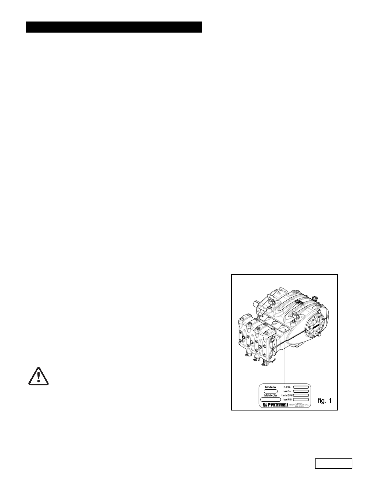
4. PUMP IDENTIFICATION
Each pump has a specific label which contains:
Pump model and version
Serial Number
Flow Rate - GPM
Pressure - PSI
Power - Hp-kW
Maximum RPM
Pump model, version and serial number must always
be specified when ordering spare parts.
Ref 300790 Rev. H
03-18
Page 6

GENERAL PUMP
5. TECHNICAL FEATURES
A member of the Interpump Group
MW SERIES
MODEL RPM
MW32A 1500/1800/2200 36.0 136 4350 300 106 79
MWS36A 1500/1800/2200 45.5 172 3900 269 121 90
MWS40A 1500/1800/2200 56.0 213 3050 210 117 87
MWS45A 1500/1800/2200 71.0 269 2500 172 121 90
MWS50A 1500/1800/2200 87.5 333 2000 138 119 88
MWS55A 1500/1800/2200 105.5 400 1450 100 104 77.5
FLOW RATE PRESSURE POWER
GPM l/min PSI Bar Hp kW
Ref 300790 Rev. H
03-18
Page 7
GENERAL PUMP
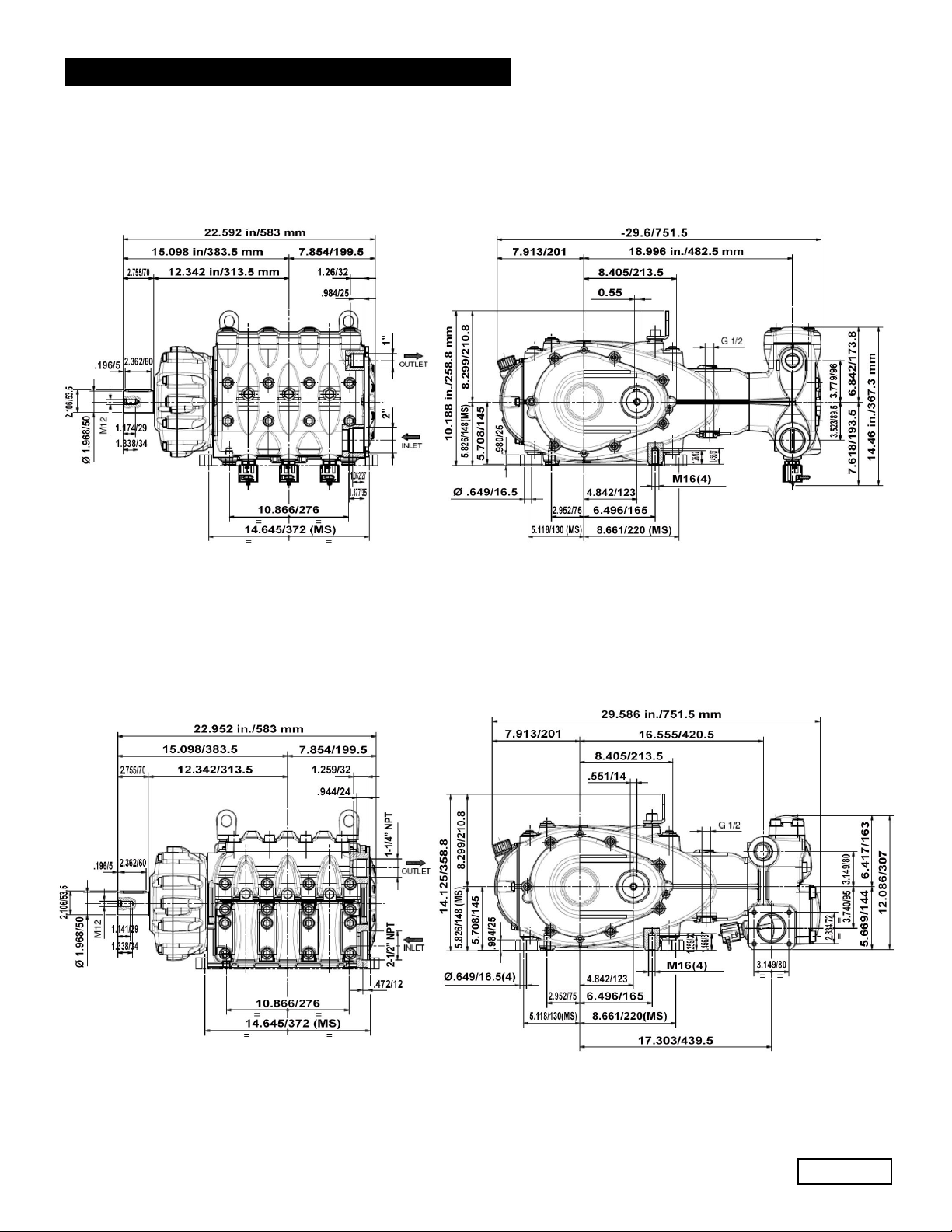
6. DIMENSIONS AND WEIGHT
For dimensions and weight of MW32A, MWS36A and MWS40A pumps, please refer to fig. 2.
A member of the Interpump Group
MW SERIES
Weight: 540 Lbs./244 Kg.
For dimensions and weight of MWS45A, MWS50A and MWS55A pumps, please refer to fig. 2a.
fig. 2
Weight: 540 Lbs./245 Kg.
fig. 2a
Ref 300790 Rev. H
03-18
Page 8
GENERAL PUMP
A member of the Interpump Group
7.INFORMATION ABOUT PUMP USE
MW SERIES
The MW/S pump was designed to operate with filtered water (see paragraph 9.7) and at
maximum temperature of 104
Other fluids may be used only upon the approval of The Customer Service Department .
7.1 WaterTemperature
The max water temperature is 104
of up to 1400F (600C) for short periods of time. In this case we advise consulting the Customer Service
Department.
7.2 Max Flow Rate and Pressure Values
The performance values indicated in the catalog refer to the maximum performance of the pump. Regardless of the power
used, pressure and maximum RPM values indicated on the plate may not be exceeded unless expressly authorized by the
Customer Service Department.
7.3 Lowest RPM
Any RPM value different from what is indicated in the performance table (see chapter 5) must be expressly authorized by
the Customer Service Department.
7.4
Recommended Lubricant Oil Types & Manufacturers
The pump is delivered with lubricant oil compliant with room temperatures ranging between 32
300C ). Some recommended lubricant types are indicated in the table below; these lubricants are treated with additives
in order to increase corrosion protection and resistance to fatigue. As an alternative, Automotive SAE 85W-90 gearing
lubricants may also be used.
0
F (400 C).
0
F (400 C).However, it is possible to use the pump at temperatures
0
and 89.60 F (00 and
BRAND TYPE
GENERAL PUMP SERIES 220
ARAL Aral Degol BG220
BP ENERGOL HLP 220
CASTROL
ELF
ESSO NUTO 220
FINA Cirkan 220
FUCHS RENOLIN 220
MOBIL DTE OIL BB
SHELL TELLUS C 220
TEXACO RANDO HD 220
TOTAL CORTIS 220
Hyspin VG 220, Magna
POLYTELIS 220
220
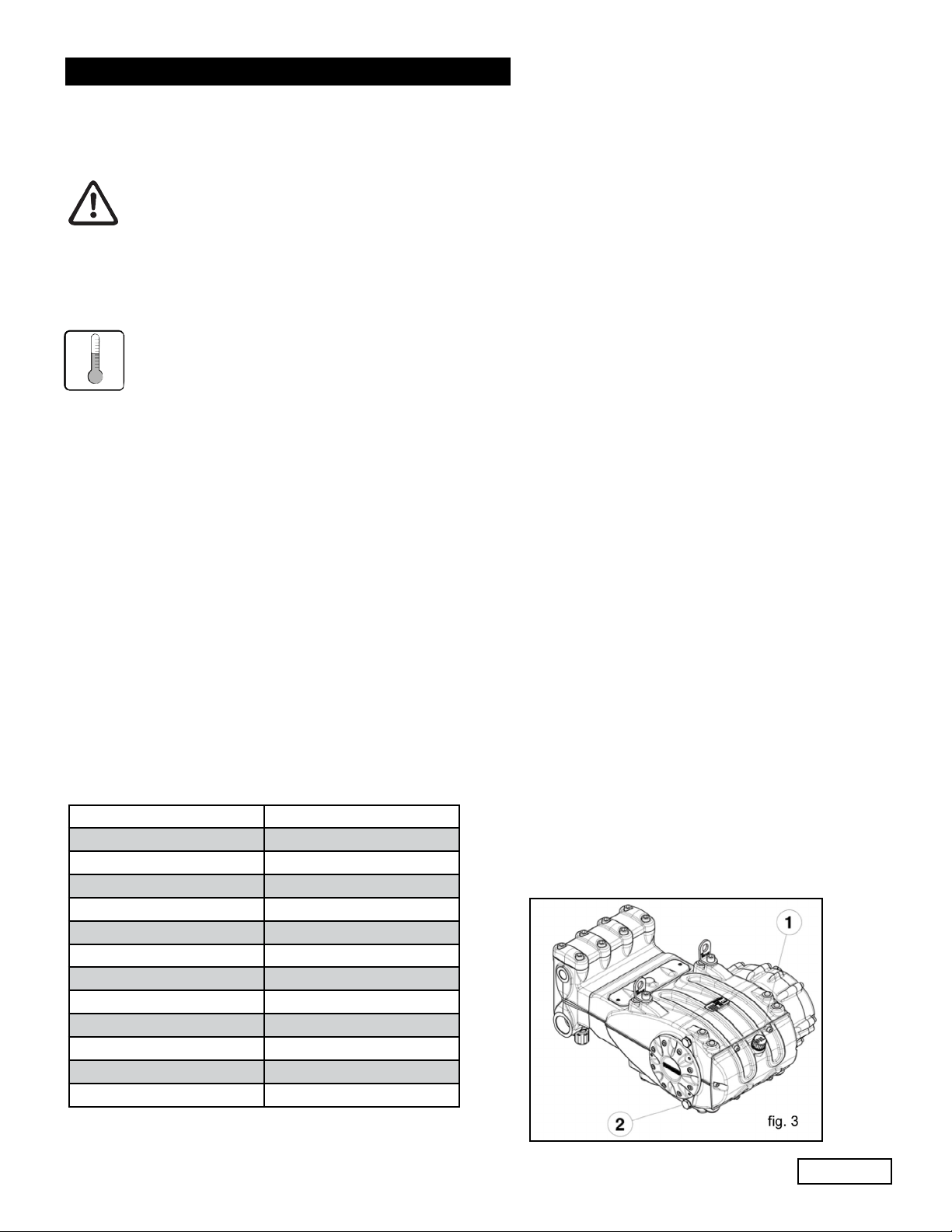
Check the oil level by using the oil level dipstick (1),
fig. 3. Refill if necessary to top off level. Correct oil level
inspection is done with the pump at room temperature;
oil is changed with the pump at working temperature, by
removing the rear plug (2), fig 3..
Checking and changing oil is to be carried out as indicated
in Chapter 11. The amount required is 304 oz. (9 liters).
Ref 300790 Rev. H
03-18
Page 9
GENERAL PUMP
In any case, oil must be changed at least once a year since it may deteriorate by oxidation.
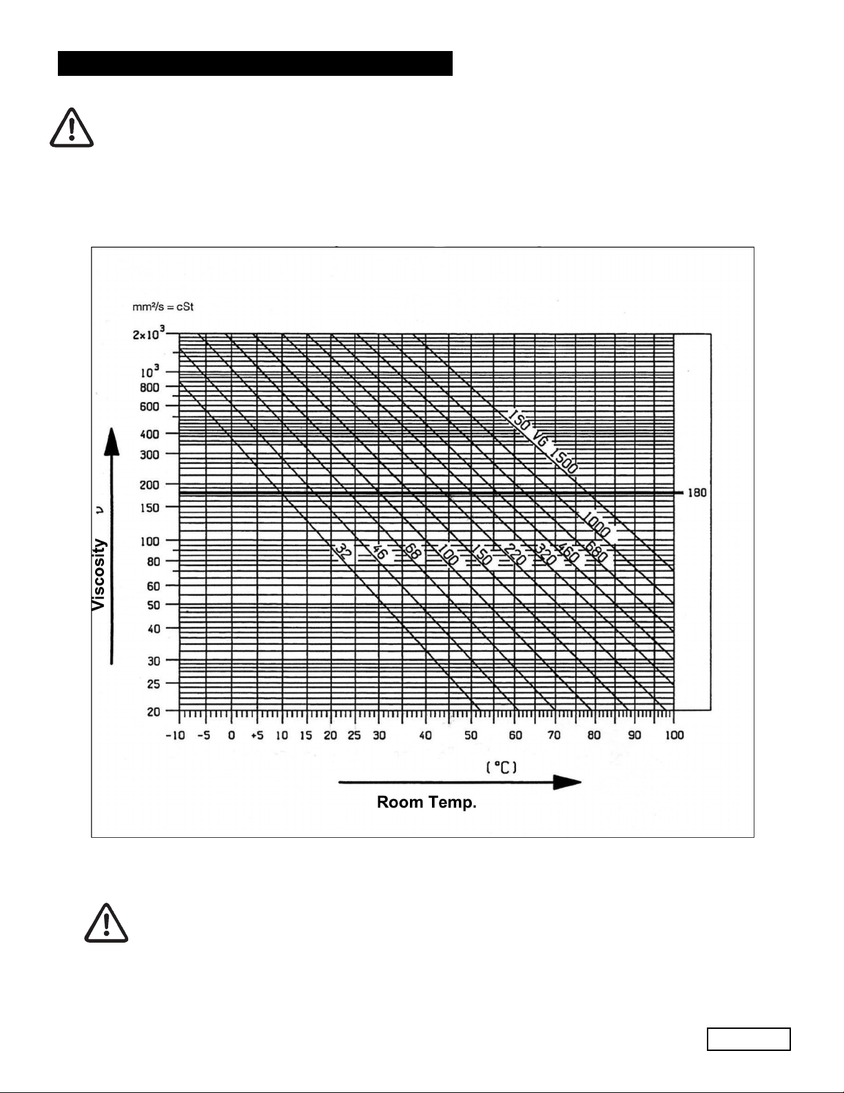
For room temperatures that differ from that mentioned earlier, follow the indications contained in the diagram
below, keeping in mind that the oil must have a minimum viscosity of 180 cSt.
A member of the Interpump Group
VISCOSITY/ROOM TEMPERATURE DIAGRAM
MW SERIES
Exhausted oil must be collected in an appropriate recipient and disposed of in appropriate
locations. In absolutely no case may it be dispersed into the environment.
Ref 300790 Rev. H
Page 10
03-18
GENERAL PUMP
A member of the Interpump Group
MW SERIES
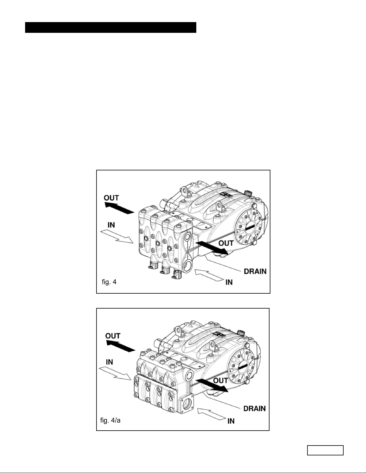
8. PORTS AND CONNECTIONS
MW/S Series pumps are equipped with (see fig. 4 and 4a):
1. 2 inlet ports “IN”, 2” NPT (MW32A, MWS36A, MWS40A).
2 inlet ports “IN”, 2-1/2” NPT (MWS45A, MWS50A, MWS55A).
The line can be connected to either of the two inlet ports; the ones not being used must be hermetically sealed.
2. 2 outlet ports “OUT”, Ø 1” NPT-F (MW32A, MWS36A, MWS40A).
2 outlet ports “OUT”, Ø 1-1/4” NPT-F (MWS45A, MWS50A, MWS55A).
3. 1 drain port “DRAIN” with G1/2” hole in the lower cover to monitor any water leakage due to wear of the pressure
packings. In case of leaks, please consult the repair manual.
This hole must always be kept open.
Ref 300790 Rev. H
03-18
Page 11
GENERAL PUMP
A member of the Interpump Group
MW SERIES
9. PUMP INSTALLATION
9.1 Installation
The pump must be installed in a horizontal position using the M16 threaded support feet.
Tighten the screws with a torque of 200 Nm (147.5 Ft-Lb)
The base must be perfectly flat and rigid enough as not to allow bending or misalignment on the pump coupling and
axis/transmission due to torque transmitted during operation.
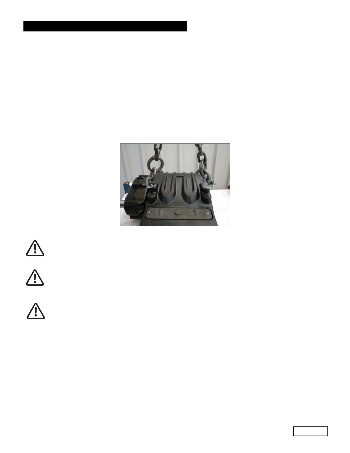
Two lifting brackets are mounted on the pump for easy installation, as per the figure below.
The brackets are sized soley for pump lifting and therefore are absolutely not permitted for use
of additional loads.
Replace the oil filling hole closing service plug positioned on the rear casing cover with the
plug with oil dipstick. Check the correct quantity.
The dipstick must always be reachable, even when the unit is assembled.
The pump’s shaft (PTO) must not be rigidly connected to the motor unit.
The following transmission types are suggested:
• Flexible joint
• Cardan Joint (please respect the maximum working angles indicated by the manufacturer)
• Belts; for correct application, please contact the Customer Service Department.
Ref 300790 Rev. H
03-18
Page 12
GENERAL PUMP
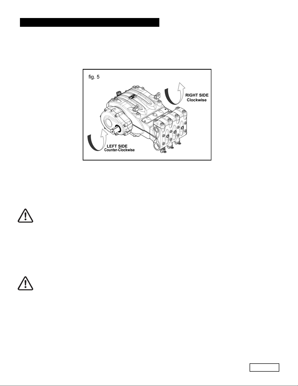
9.2 Direction of rotation
The PTO rotation is indicated by an arrow located on the reduction gear cover. From a position facing the pump head,
the rotation direction will be as in fig. 5.
A member of the Interpump Group
MW SERIES
9.3 Version Change and Reducer Positioning
A right version pump is defined when: observing the pump from the head side, the PTO shank of the pump shaft is on
the right side.
A left version pump is defined when: observing the pump from the head side, the PTO shank is on the left side.
See fig. 5.
The version may be changed only by trained and authorized personnel by carefully
following the instructions in the repair manual.
1. Separate the pump head from the power end (crankcase) as indicated in Chapter 2 in points 2.2.1 and 2.2.3 of the
Repair Manual.
2. Turn the power end (crankcase) 180
turned upward. Reposition the lifting bracket and relative hole closing plugs in the upper part of the casing. Invert
the two inspection covers, ensuring that the open one is positioned lower. Finally, properly reposition the
specification label in its housing on the casing.
Make sure that the lower inspection cover draining holes are open.
3. Reassemble the pump head with the power end (crankcase( as indicated in Chapter 2 in points 2.2.1 and 2.2.4 of
the Repair Manual.
o
and reposition the rear casing cover in such a way that the oil dipstick is
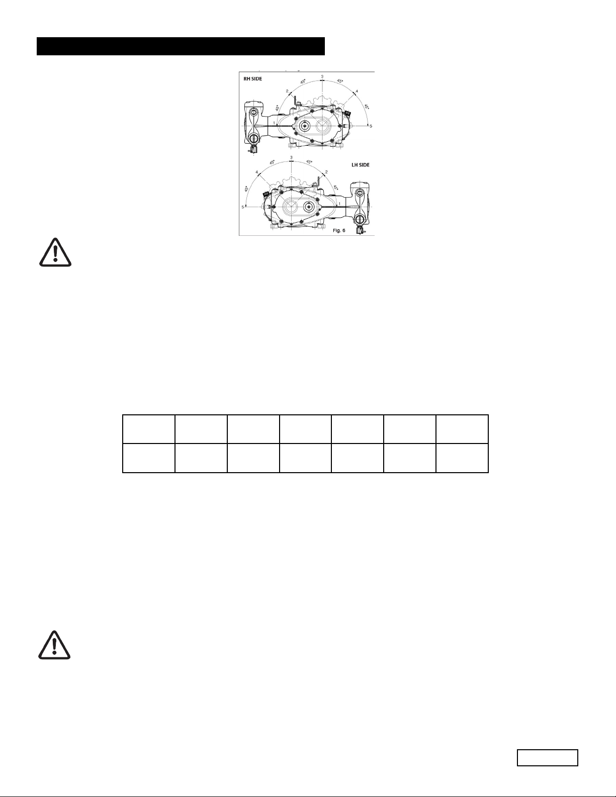
It is also possible to place the reduction gear in 5 different positions as per fig. 6.
Ref 300790 Rev. H
03-18
Page 13
GENERAL PUMP
The reducer’s position may be changed only by trained and authorized personnel by carefully following
the instructions in the repair manual.
9.4 Hydraulic Connections
In order to isolate the system from the vibrations produced by the pump, we advise to build the first section of the duct
near the pump (both for intake and delivery) with flexible hose. The consistency of the intake section must allow to avoid
deformation caused by the depressurization produced by the pump.
A member of the Interpump Group
MW SERIES
fig. 6
9.5 Pump Power Supply
MW/S pumps must always be installed under positive head, i.e. they must receive water by gravity or by forced feeding,
and never suctioned from a lower level. The pumps can tolerate minimum NPSH even as low as 1 m. (3.28 ft.), however, to obtain a better volumetric efficiency and above all to avoid cavitation, the minimum NPSH available, measured at
the pump inlet flange, will have to be at least equal or higher than the values shown in the chart below.
MW32A MWS36A MWS450A MWS45A MWS50A MWS55A
NPSHr (ft) 4.5 5.5 6.5 7.5 8 9
For higher cylinder capacity pumps (MWS45A-S50A-S55A), it is strongly recommended to use a booster pump to avoid
cavitation, in view of the geometry on the hydraulic section and of the remarkably high flow rates.
The booster pump must have the following specifications: flow rate at least double the rated flow rate of the pump, and
pressure between 30 to 40 PSI (2 to 3 Bar). These feeding conditions must be respected at any operating RPM.
Booster start-up must always precede plunger pump start-up. In order to protect the pump, we advise to
install a pressure switch on the feeding line after the filters.
Ref 300790 Rev. H
03-18
Page 14
GENERAL PUMP
9.6 Suction Line
For the pump’s correct operation, the suction line must have the following characteristics:
1. Minimum internal diameter as indicated in the diagram in paragraph 9.9, and in any case equal or greater than
the pump head’s value. Along the duct, avoid localized diameter reductions that may cause pressure drops with
subsequent cavitation. Absolutely avoid 900 elbows, connections with other hoses, bottlenecks, counter-slopes,
upside down “U” shaped curves, “T” connections.
2. With a layout that is set in such a way to prevent cavitation.
3. It should be perfectly airtight, and built in a way that guarantees perfect sealing over time.
4. Avoid pump emptying when stopping (even partial emptying).
5. Do not use hydraulic fittings, 3 or 4 way fittings, adapters, etc., since they may hinder the pump’s performance.
6. Do not install Venturi tubes or injectors for detergent intake.
7. Avoid the use of standing valves, check valves, or any other type of one-way valves.
8. Do not connect the by-pass line from the valve directly to the pump suction line.
9. Provide appropriate baffle plates inside the tank in order to avoid water flows coming from both the by-pass and
feeding which lines may create turbulance near the tank’s outlet port.
10. Make sure that the suction line is perfectly clean inside before connecting it to the pump.
11. The pressure gauge for checking booster pressure must be installed near the plunger pump’s inlet port, and always
downstream from the filters.
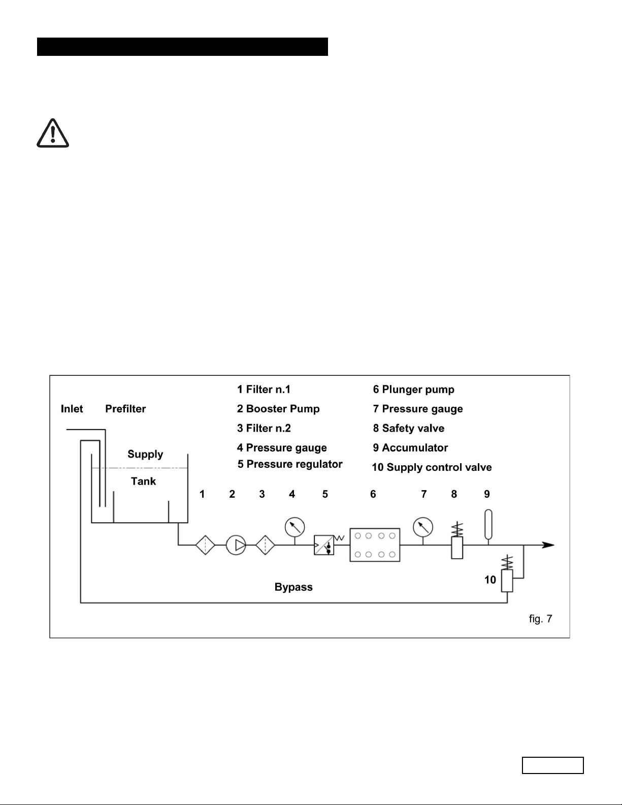
9.7 Filtering
On the suction line, install two filters as indicated in fig. 7 and fig. 7/a.
A member of the Interpump Group
MW SERIES
With the manual adjustment valve:
Ref 300790 Rev. H
03-18
Page 15
 Loading...