

GP MF Series, MF45, MF50, MF55 Repair Manual
MF
8
Repair Manual
General Pump
is a member of
the Interpump Group
MF45 - MF50 - MF55
Ref 310068 Rev.A
06-17

GENERAL PUMP
INDEX
1. INTRODUCTION ..................................................Page 3
2. REPAIR INSTRUCTIONS ...........................................Page 3
2.1 Repairing Mechanical Parts .......................................Page 3
2.1.1 Disassembling of Mechanical Parts ..........................Page 4
2.1.2 Assembly of Mechanical Parts ..............................Page 15
2.1.3 Increase and Reduction Classes ............................ Page 27
2.2 Repairing Hydraulic Parts ........................................Page 27
2.2.1 Disassembling manifold MF45, MF50, MF55: valve inserts ........Page 27
2.2.2 Disassembling manifold MF45, MF50, MF55: sleeves containg seals Page 30
2.2.3 Fitting the manifold .......................................Page 32
2.2.4 Fitting the manifold: sleeves containing seals ..................Page 33
2.2.5 Assembling the valve units manifold ......................... Page 36
2.2.6 Disassembling the piston unit ............................... Page 43
2.2.7 Assembling the piston unit .................................Page 44
3. SCREW CALIBRATION ............................................Page 47
4. REPAIR TOOLS ..................................................Page 47
A member of the Interpump Group
MF SERIES
5. REPLACING THE CON-ROD SMALL END BUSH ....................... Page 48
6. MAINTENANCE LOG ..............................................Page 49
Ref 310068 Rev.A
06-17
Page 2
GENERAL PUMP
A member of the Interpump Group
MF SERIES
1. INTRODUCTION
This manual describes the instructions for Repairing MF Series pumps, and must be carefully read and
understood before performing any repair intervention on the pump. Proper pump operation and longevity
depend on the correct use and maintenance. General Pump declines any responsibility for
damage caused by the misuse or the non-observance of the instructions described in this manual.
2. REPAIR INSTRUCTIONS
2.1 Repairing Mechanical Parts
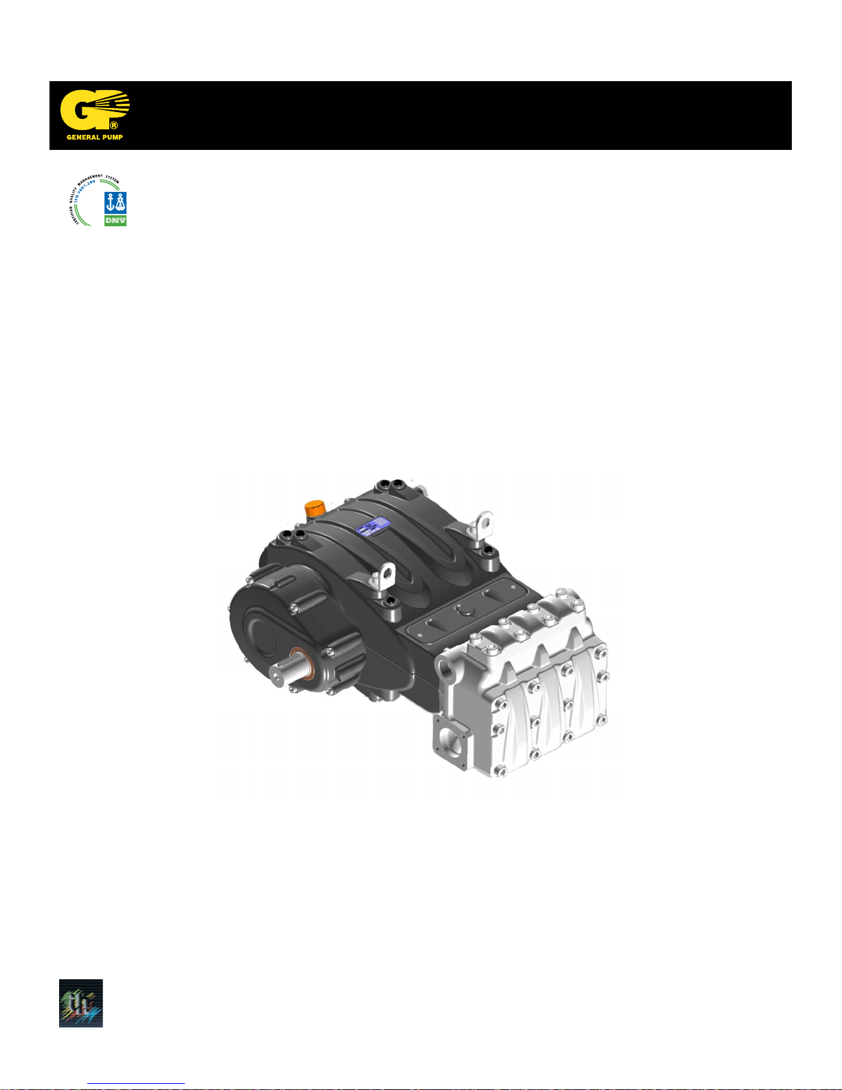
Mechanical parts repair must be performed after removal of oil from the casing. To drain
the oil, remove the oil dipstick, (1, fig. 1) and then the draining plug (2, fig. 1).
The oil must be placed in a suitable container and disposed of in special centers.
It absolutely must not be discarded into the environment.
Ref 310068 Rev.A
06-17
Page 3
GENERAL PUMP
2.1.1 Disassembly of Mechanical Parts
The correct sequence is the following:
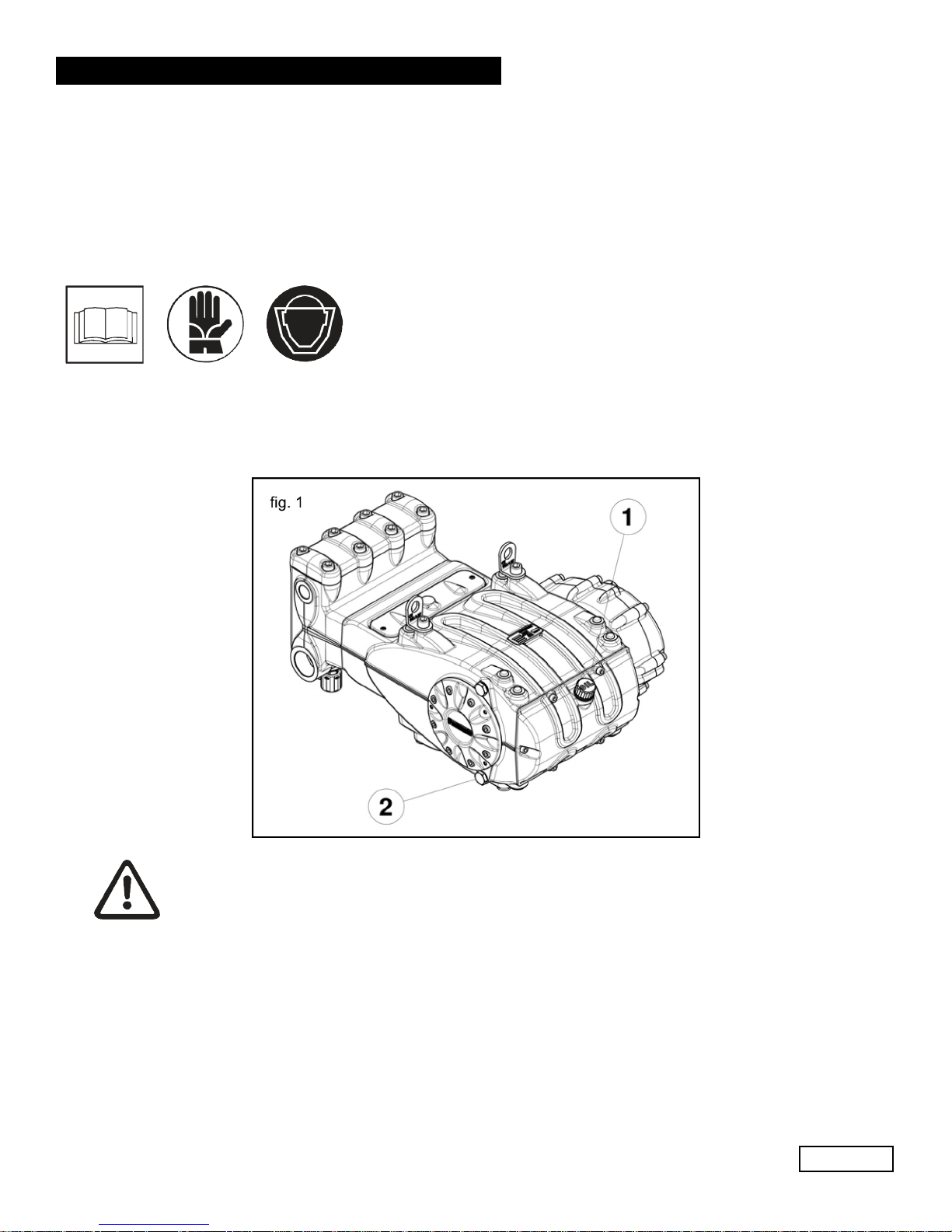
Completely drain the oil from the pump, then disassemble the casing cover (and relative o-ring), unscrewing
the 6 M10 screws (1, fig. 2).
A member of the Interpump Group
MF SERIES
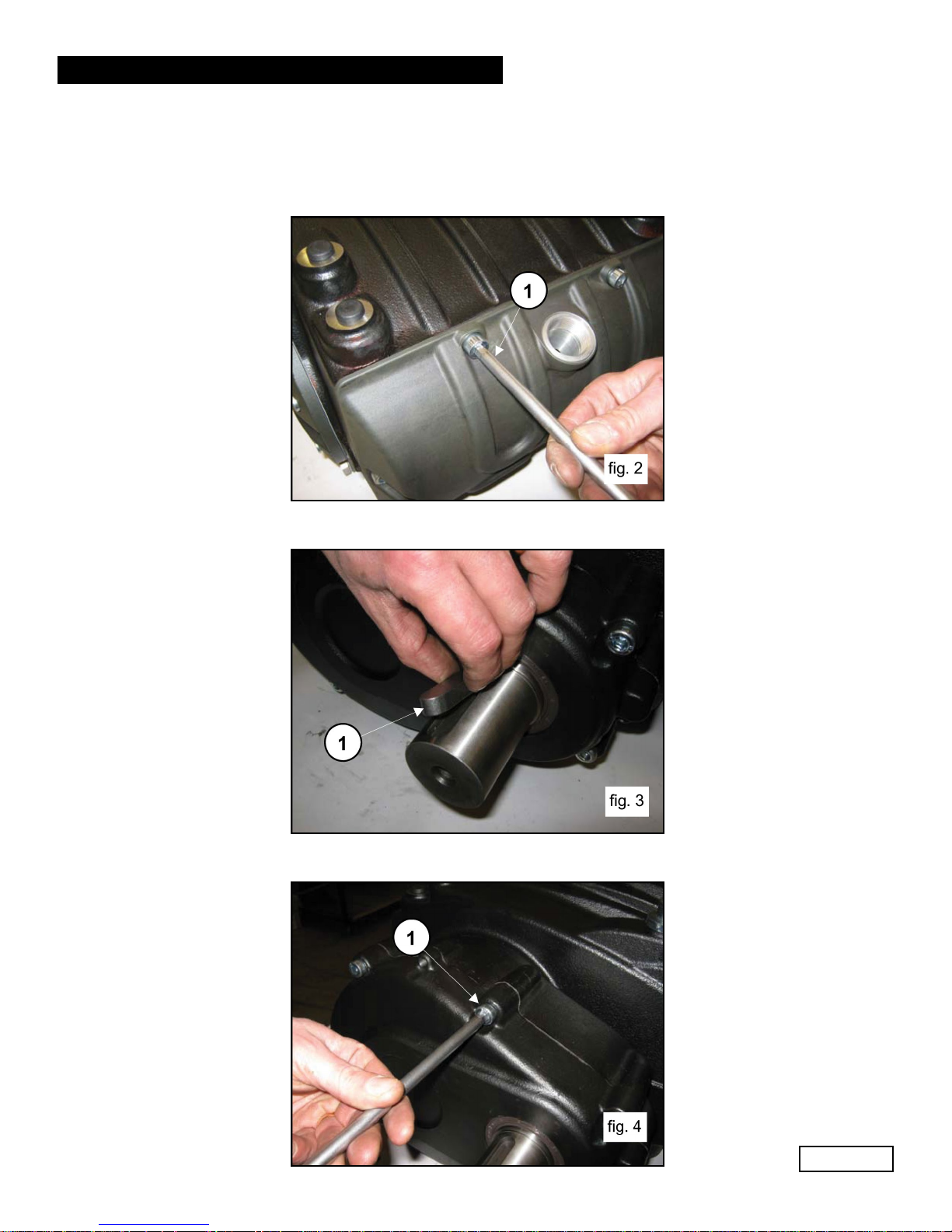
Remove the tab from the PTO shaft (2, fig. 3).
Unscrew the reduction gear cover fixing screws (1, fig. 4).
Ref 310068 Rev.A
06-17
Page 4
GENERAL PUMP
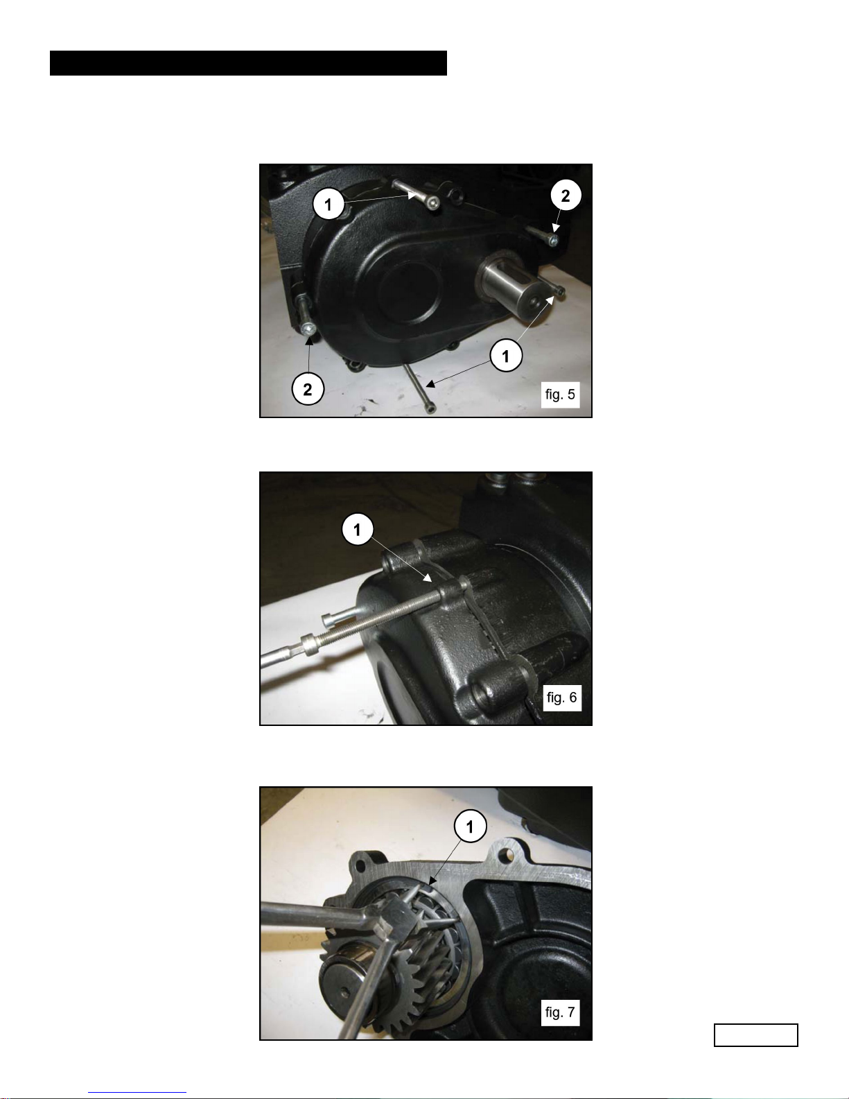
Position the 3 grub screws or M8 threaded screws (1, fig. 5) with the function of extractors in the holes and
two sufficiently long M10 screws with the function of supporting the cover (2, fig. 5).
Slowly screw in the 3 M8 screws (1, fig. 6) with the function of extractors to fully remove the cover unit
and pinion.
A member of the Interpump Group
MF SERIES
Complete disassembly of the reduction gear cover from the pinion is possible following these steps:
Remove the retaining ring Ø120 (1, fig. 7)
Ref 310068 Rev.A
07-17
Page 5
GENERAL PUMP
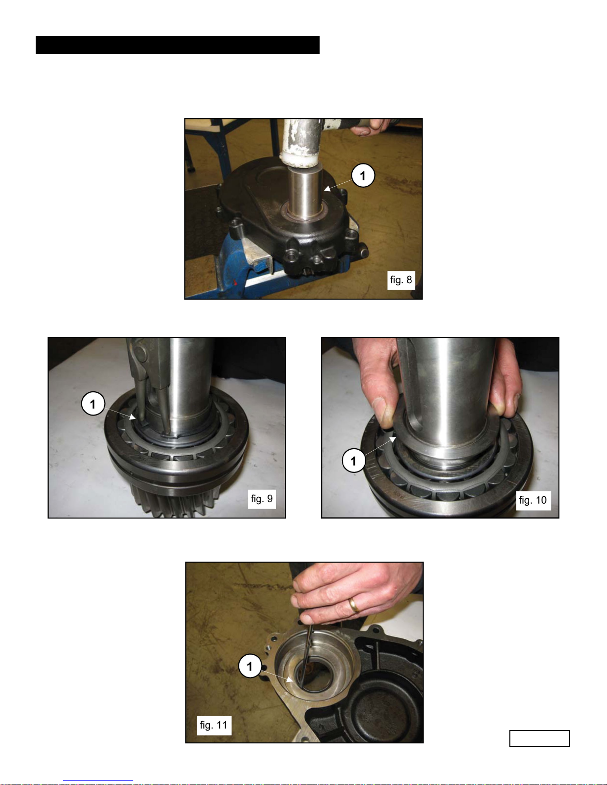
Separate the pinion from the cover, working with an extractor hammer on the pinion itself (1, fig. 8).
Remove the retaining ring Ø55 (1, fig. 9) and the bearing support ring (1, fig. 10) from the pinion.
A member of the Interpump Group
MF SERIES
Extract the seal ring from the reduction gear cover, working from the inner side of the cover (1, fig. 11).
Ref 310068 Rev.A
06-17
Page 6
GENERAL PUMP
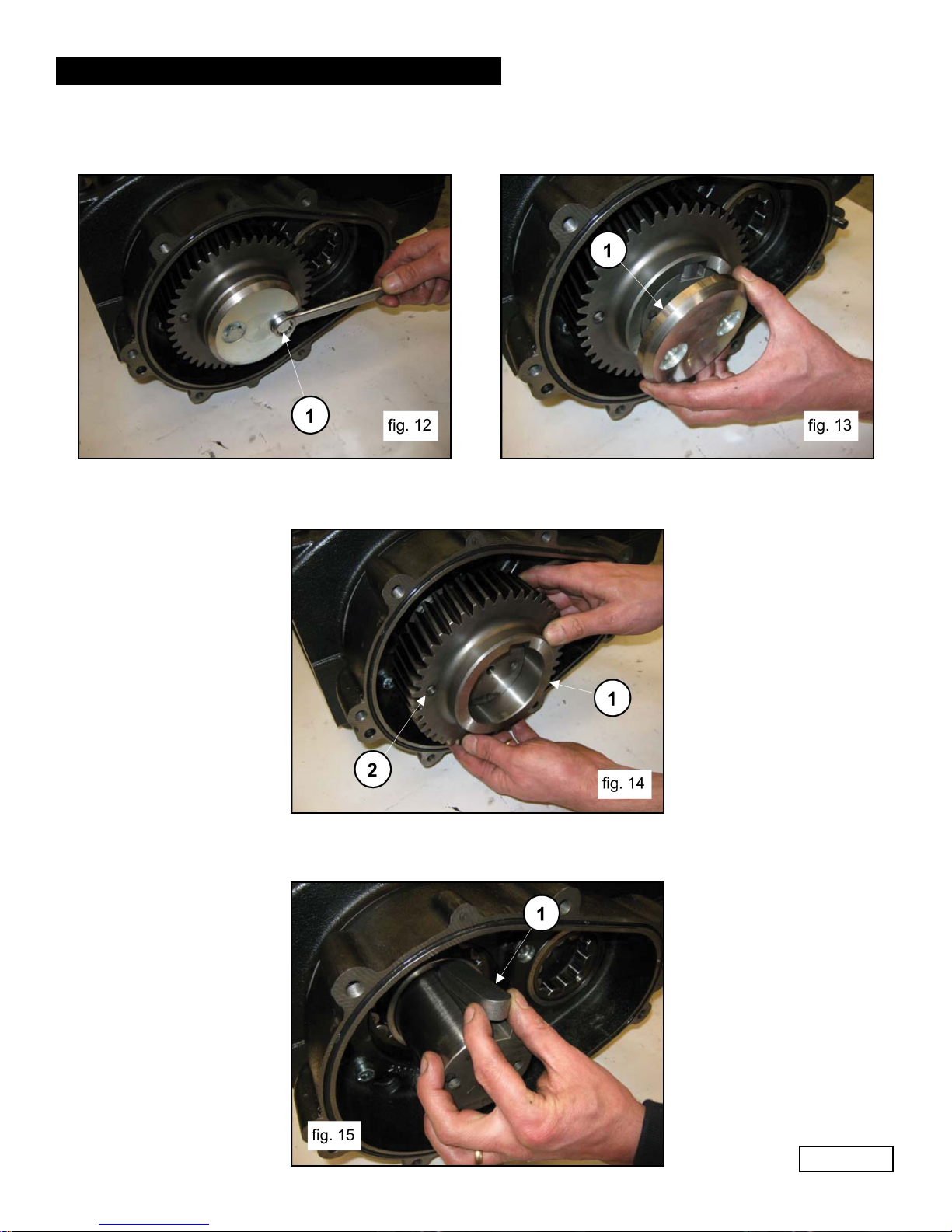
Unscrew the screws holding in the ring gear (1, fig. 12) and remove it (1, fig. 13).
Remove the ring gear (1, fig. 14). Where necessary, it is possible to utilize an extractor hammer to be
applied on the 2 M8 holes (2, fig. 14).
A member of the Interpump Group
MF SERIES
Remove the key from the shaft (1, fig. 15).
Ref 310068 Rev.A
06-17
Page 7
GENERAL PUMP
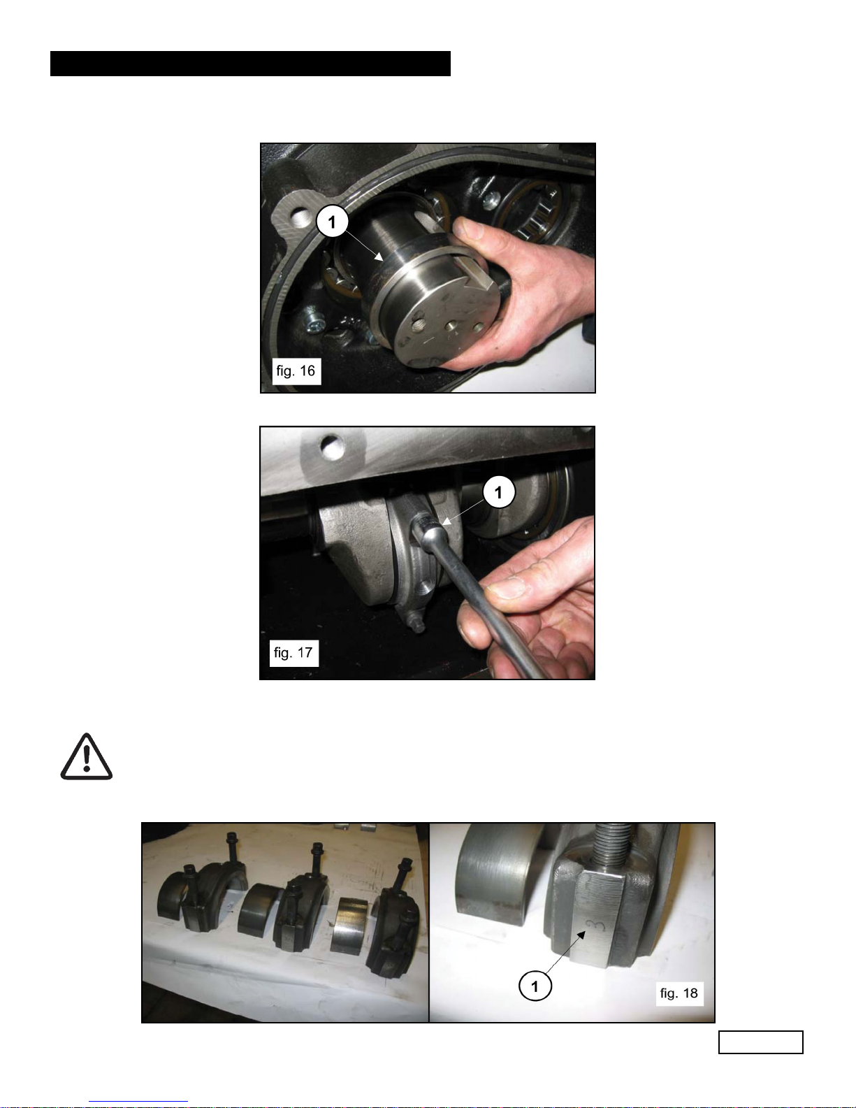
Remove the ring gear support ring (1, fig. 16).
Unscrew the connecting rod screws (1, fig. 17).
A member of the Interpump Group
MF SERIES
Remove the connecting rod caps with the lower semi-bearings, taking special care of the disassembly
sequence during disassembly.
The con-rod caps and their relative half supports must be reassembled in exactly the same
order and coupling with which they were disassembled.
To avoid possible errors, caps and half-supports have been numbered on one side (1, fig. 18).
Ref 310068 Rev.A
06-17
Page 8
GENERAL PUMP
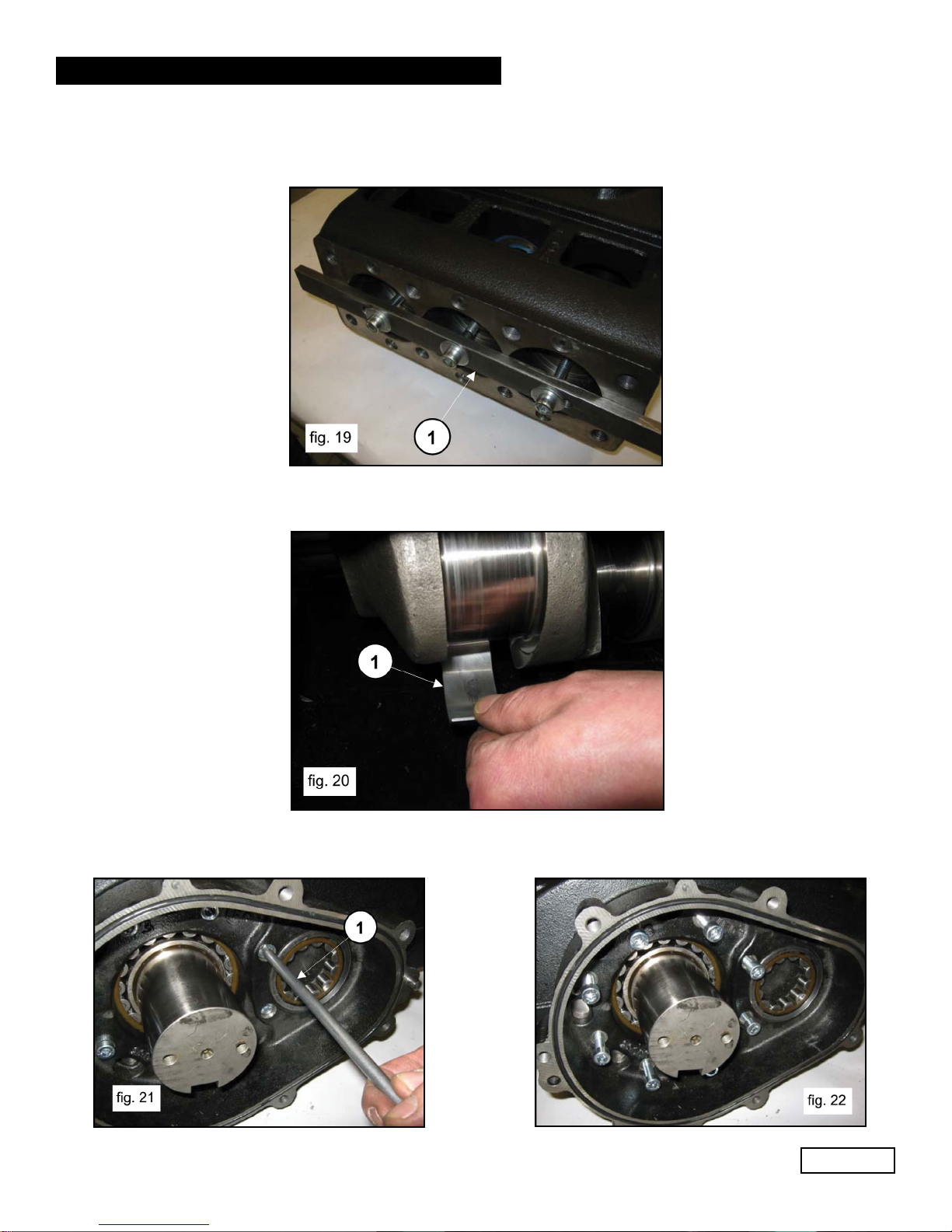
Advance the half supports completely in the direction of the pump head to allow the crankshaft to come
out. To facilitate this operation, use special tool (p/n F27566200) (1, fig. 19).
Remove the three upper half-bearings of the half supports (1, fig. 20).
A member of the Interpump Group
MF SERIES
Unscrew the reduction gear box fixing screws (1, fig. 21 and fig. 22).
Ref 310068 Rev.A
06-17
Page 9

GENERAL PUMP
Position the 3 grub screws or M8 threaded screws (1, fig. 23) with the function of extractors in the holes and
two sufficiently long M10 screws with the function of supporting the reduction gear box (2, fig. 23).
Slowly screw in the 3 M8 screws (1, fig. 24) to prevent the box from tilting too far and getting locking in the
housing. Remove the box while supporting the shaft to prevent damage (1, fig. 25)
A member of the Interpump Group
MF SERIES
Unscrew the bearing cover fixing screws from the opposite side (1, fig. 26 and fig. 27).
Ref 310068 Rev.A
06-17
Page 10
GENERAL PUMP
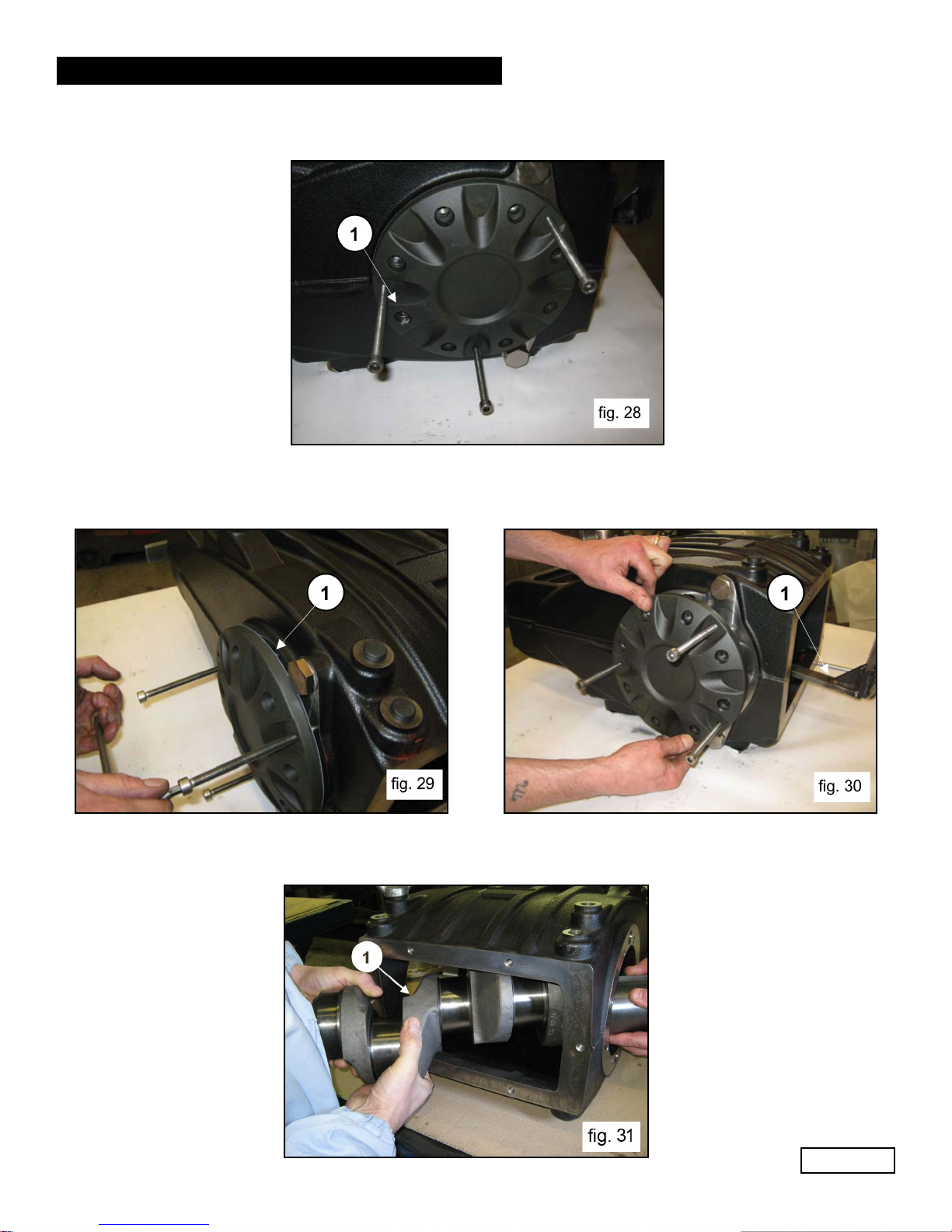
Position the 3 grub screws or M8 threaded screws (1, fig. 28) with the function of extractors in the holes.
Slowly screw in the 3 M8 screws (1, fig. 29) to prevent the cover from tilting too far and getting locked in the
housing. Remove the bearing cover while supporting the shaft to prevent damage (1, fig. 30).
A member of the Interpump Group
MF SERIES
Remove the crankshaft from the rear opening (1, fig. 31)
Ref 310068 Rev.A
06-17
Page 11
GENERAL PUMP
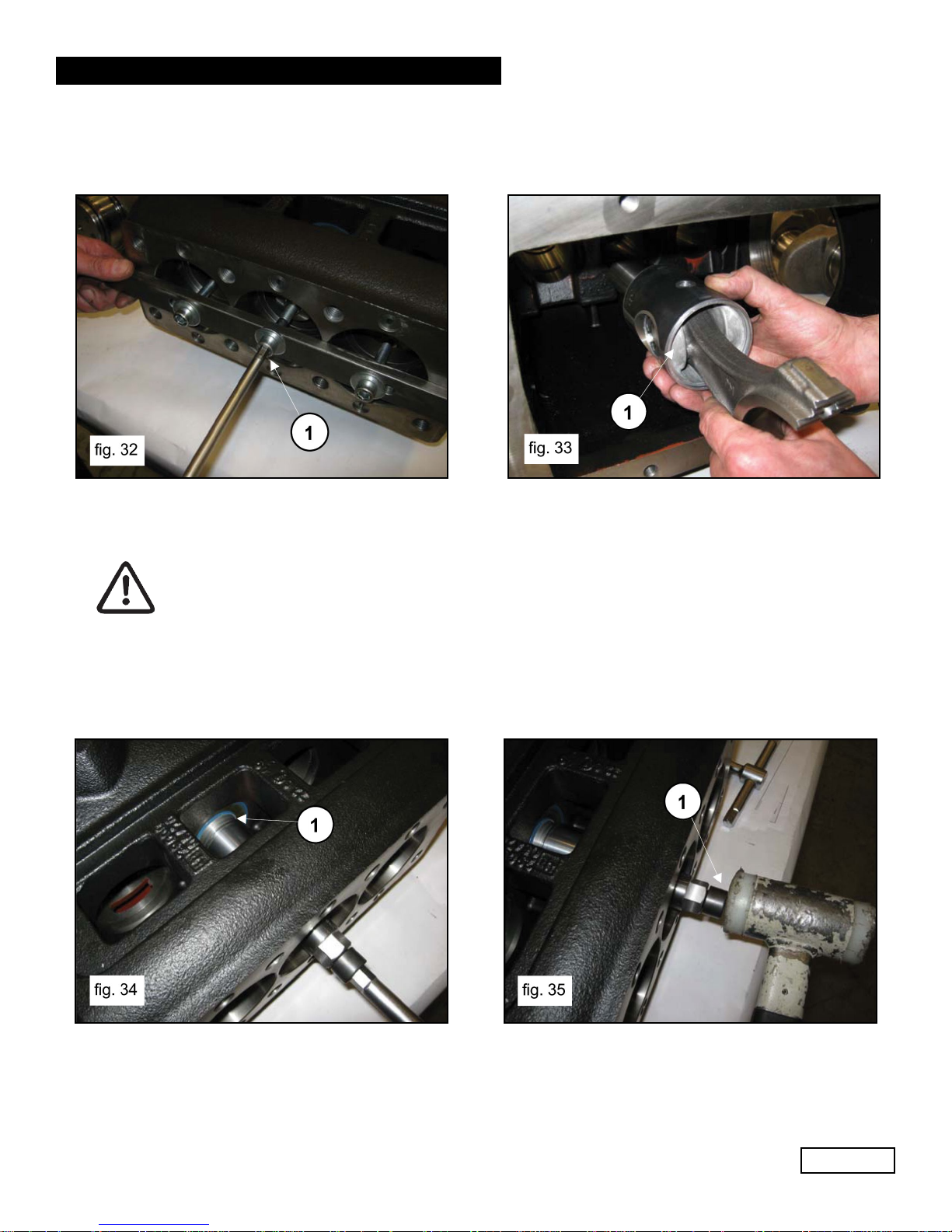
In the event that it is necessary to replace one or more con-rods or plunger guides, operate as follows:
Unscrew the screws with tool #F27566200 to unlock the con-rods (1, fig. 32) and then extract the con-rod
plunger guide units from the back casing opening (1, fig. 33).
It is now possible to disassemble the plunger guide seal rings, taking care to not damage the plunger guide
sliding rod.
Whenever it becomes necessary to replace the plunger guide seal rings without
dismantling the entire mechanical part, it is possible to extract the seal rings with the
use of tool #F27918500 operating as follows:
A member of the Interpump Group
MF SERIES
Insert the tool between the rod and the seal ring (1, fig. 34) and, with the extractor hammer, complete
insertion of the tapered section inside the seal ring (1, fig. 35).
Ref 310068 Rev.A
06-17
Page 12
GENERAL PUMP
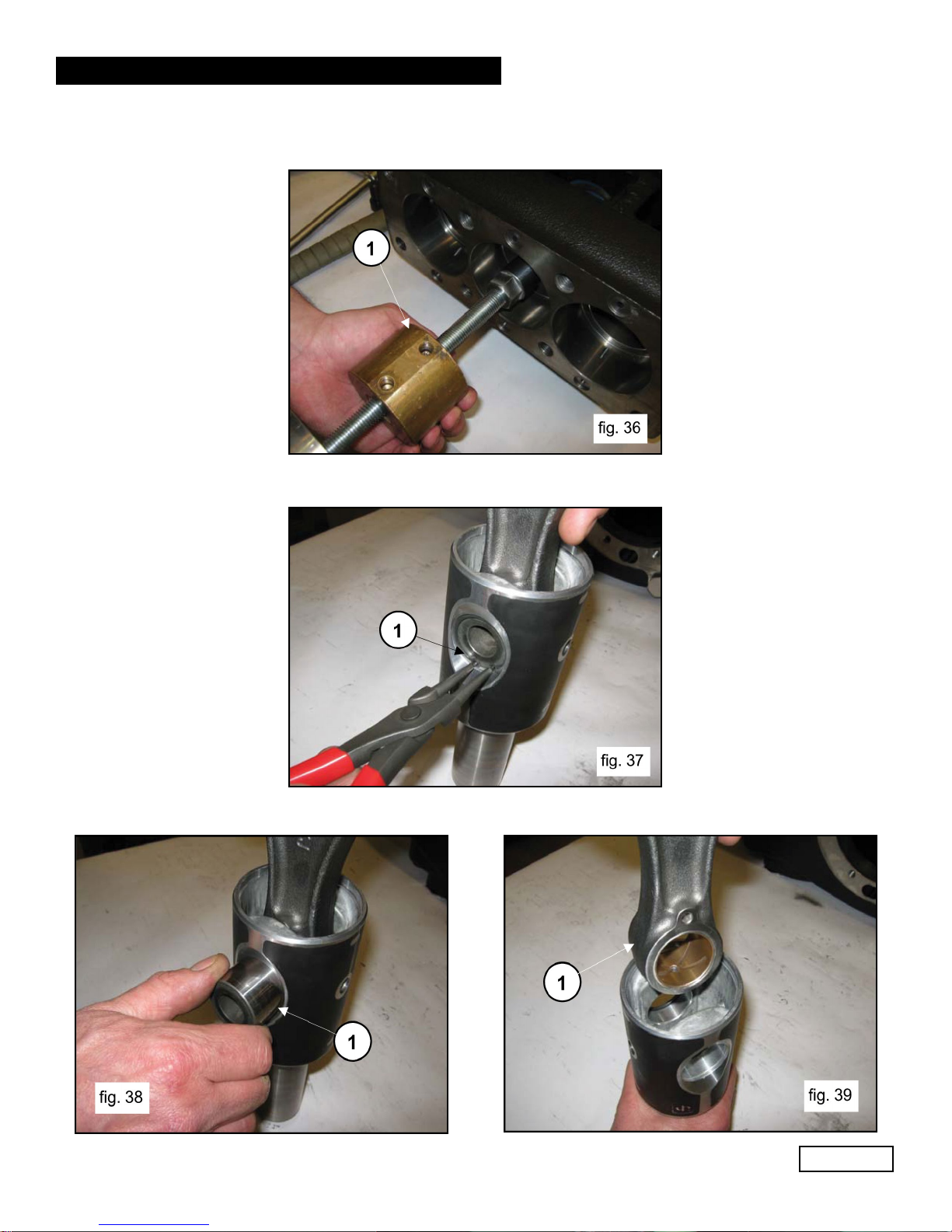
Extract the seal ring using the tool extractor hammer (1, fig. 36).
Remove the two spindle locking retaining rings Ø120 (1, fig. 37).
A member of the Interpump Group
MF SERIES
Remove the spindle (1, fig. 38 and extract the con-rod (1, fig. 39).
Ref 310068 Rev.A
06-17
Page 13
GENERAL PUMP
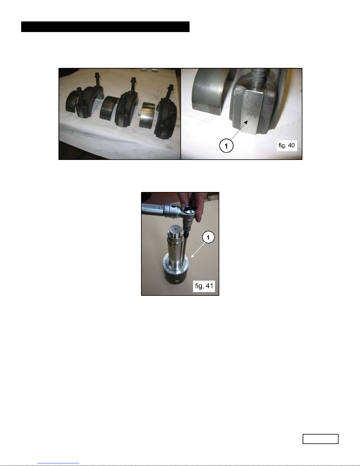
Couple the half supports to the previously disassembled caps, referring to the numbering (1, fig. 40).
To separate the rod from the piston guide, unscrew the round head M6 screws (1, fig. 41)
A member of the Interpump Group
MF SERIES
Ref 310068 Rev.A
06-17
Page 14

GENERAL PUMP
2.1.2 Assembly of Mechanical Parts
Proceed with assembly following the reverse order indicated in point 2.1.1. The proper sequence is as
follows:
Assemble the rod to the plunger guide. Insert the piston guide rod into its seat on the piston guide (1, fig. 42)
and join the rod to the piston guide by means of M6 x 20 screws (1, fig. 43).
A member of the Interpump Group
MF SERIES
Lock the piston guide in a vice (1, fig. 44) and proceed with calibration with a torque wrench (1, fig. 45) as
indicated in paragraph 3 “Screw Tightening Calibration”.
Insert the con-rod in the piston guide (1, fig. 39) and then insert the piston pin (1, fig. 38). Apply the two
spindle locking retaining rings (1, fig. 37).
Assembly has been carried out properly if the con-rod small end, piston guide and
spindle rotate freely.
Separate the caps from the con-rods. Proper coupling can be verified by the numbering on the side
(1, fig. 40).
After having checked casing cleaning, proceed with assembly of half support-piston guide unit inside
casing rods (1, fig. 33).
Insertion of the conrod-plunger guide unit in the casing must be made with the
half bearings set in the direction in which numbers are visible from above.
Ref 310068 Rev.A
06-17
Page 15
 Loading...