

GP MF series, MF50, MF55, MF45 Owner's Manual
MF
8
Owner’s Manual
• Installation
• Use
• Maintenance
General Pump
is a member of
the Interpump Group
MF45 - MF50 - MF55
Ref 310069 Rev. B
07-18

GENERAL PUMP
A member of the Interpump Group
MF SERIES
INDEX
1. INTRODUCTION ............................................................... Page 3
2. DESCRIPTION OF SYMBOLS ....................................................Page 3
3. SAFETY ...................................................................... Page 4
3.1 General safety instructions ....................................................Page 4
3.2 High pressure unit safety requirements ........................................... Page 4
3.3 Safety during operation ....................................................... Page 4
3.4 General procedures for using nozzles ............................................ Page 4
3.5 Safety during unit maintenance .................................................Page 5
4. PUMP IDENTIFICATION ......................................................... Page 5
5. TECHNICAL FEATURES ........................................................Page 6
6. DIMENSIONS AND WEIGHT ..................................................... Page 6
7. OPERATING INSTRUCTIONS ....................................................Page 7
7.1 Water temperature ........................................................... Page 7
7.2 Maximum flow and pressure rates ............................................... Page 7
7.3 Minimum RPM ..............................................................Page 7
7.4 Recommended lubricant types and Manufacturers .................................. Page 7-8
8. PORTS AND CONNECTIONS ....................................................Page 9
9. PUMP INSTALLATION ..........................................................Page 9
9.1 Installation .................................................................Page 9
9.2 Direction of rotation .......................................................... Page 10
9.3 Version change and reducer positioning ..........................................Page 10-11
9.4 Hydraulic connections ........................................................Page 12
9.5 Pump power supply ..........................................................Page 12
9.6 Suction line ................................................................Page 12
9.7 Filtration ...................................................................Page 13
9.8 Outlet line .................................................................. Page 14
9.9 Internal diameter of hose ...................................................... Page 14
9.10 V-belt transmission .........................................................Page 15
10. START UP AND OPERATION ....................................................Page 15
10.1 Preliminary inspections ......................................................Page 15
10.2 Starting up ................................................................ Page 16
11. PREVENTATIVE MAINTENANCE ................................................. Page 16
12. PUMP STORAGE ..............................................................Page 17
12.1 Filling the pump with anti-corrosion emulsion or anti-freeze .......................... Page 17
12.2 Hoses .................................................................... Page 17
13. PRECAUTIONS AGAINST FREEZING ..............................................Page 17
14. WARRANTY TERMS ............................................................Page 17
15 TROUBLESHOOTING ...........................................................Page 18
16. EXPLODED VIEWS AND PARTS .................................................. Page 19-20
17. REPAIR TOOLS ................................................................Page 21
18. MAINTENANCE LOG ........................................................... Page 22
Ref 310069 Rev. B
07-18
Page 2
GENERAL PUMP
A member of the Interpump Group
MF SERIES
1. INTRODUCTION
This manual describes the use and maintenance instructions of the MF pump, and should be carefully read and
understood before using the pump.
Correct use and adequate maintenance will guarantee the pumps trouble-free operation for a long time. General Pump
declines any responsibility for damage caused by misuse or the non-observance of the instructions indicated in this
manual.
Upon receiving the pump, check that it is complete and in perfect condition. Should anything be found out of order, please
contact us before installing and starting the pump.
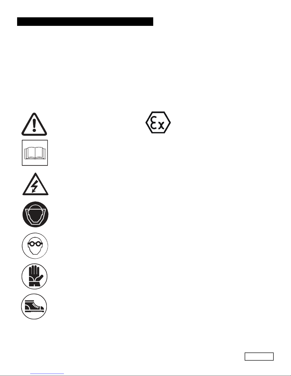
2. SYMBOL DESCRIPTIONS
Warning
Potential Danger
Read carefully and understand
the manual before operating
the pump
Danger
High Voltage
Danger
Wear protective mask
Danger
Wear goggles
Symbol for protection against
explosion.
This defines special safety requirements
for the us of the pumps in areas indentified
in accordance with the ATEX Directive.
When pumps are ordered in the ATEX
configuration because they are going
to work in areas with a potentially explosive atmosphere, you must STRICTLY
comply with the notes given under the
headings marked with this symbol and
the instructions in the supplementary
instructions manual “ATEX EXPLOSION
PROTECTION”.
(Versions available in compliance with
ATEX:MF)
Danger
Wear protective gloves
Danger
Wear protective boots
Ref 310069 Rev. B
07-18
Page 3

GENERAL PUMP
A member of the Interpump Group
MF SERIES
3. SAFETY
3.1 General Safety Indications
Improper use of pumps and high pressure systems, and the non-compliance with installation and maintenance
instructions may cause severe injury to people and/or damage to property. Anyone assembling or usinge high pressure
systems must possess the necessary competence to do so, should be aware of the characteristics of the components
assembled/used, and must take all precautions necessary to ensure maximum safety in any operating condition. In the
interest of safety, both for the Installer and the Operator, no reasonably applicable should be omitted.
3.2 High pressure unit safety requirements
1. The pressure line must always be equipped with a safety valve.
2. High pressure system components, in particular for those units working outside, must be adequately
protected against rain, frost and heat.
3. The electrical control system must be adequately protected from water spray, and must comply with the
specific regulations in force.
4. High pressure hoses must be properly sized for maximum operating pressure of the system and always and only
used within the operating pressure range specified by the hose manufacturer. The same rules should be observed
for all other auxiliary systems affected by high pressure.
5. The ends of high pressure hoses must be sheathed and secured to a solid structure to prevent dangerous
whiplash in case of bursting or broken connections.
6. Appropriate safety guards must be provided for the pump transmission systems (couplings, pulleys and belts,
auxiliary drives).
3.3 Safety During Operation
The working area of a high pressure system must be clearly marked. Access must be prohibited to un-authorized
personnel and, wherever possible, the area should restricted or fenced. The personnel authorized to access this area
should first be trained, and informed about the risks that may arise from failures or malfunctions of the high pressure unit.
Before starting the unit, the operator must check:
1. That the high pressure system is properly powered (see paragraph 9.5).
2. That pump intake filters are perfectly clean; we advise the use of a device that indicates the filters clogging level.
3. Electrical parts are adequately protected and in perfect condition.
4. The high pressure hoses do not show apparent signs of abrasion, and that fittings are in perfect shape.
Any fault or reasonable doubt that may arise before or during operation should be promptly reported and verified by
competent personnel. In these cases, pressure should immediately be released and the high pressure system stopped.
3.4 General Procedures For Using Nozzles
1. The Operator must always place his/her safety and security first, as well as that of others that may be directly
affected by his/her actions, or any other assessments or interests. The operator’s work must be dictated by common
sense and responsibility.
2. The Operator must always wear a helmet with a protective visor, waterproof clothing, and appropriate boots capable
of guaranteeing grip on wet pavement.
Ref 310069 Rev. B
07-18
Page 4
GENERAL PUMP
Note: appropriate clothing will effectively protect against water spray, but it may not offer adequate protection against the
direct impact of water jets or sprays from a close distance. Some circumstances may require further protection.
3. It is generally best to organize personnel into teams of at least two people capable of giving mutual and immediate
assistance in case of necessity and of taking turns during long and demanding operation.
4. Access to the work area that is within the water jets’ range must be absolutely prohibited to and free from objects
that, inadvertently under a pressure jet, can be damaged and or create dangerous situations.
5. The water jet must only and always be directed in the direction of the work area, including during testing or
preliminary tests or checks..
6. The Operator must always pay attention to the trajectory of the debris removed by the water jet. If
necessary, suitable guards must be provided by the Operator to protect anything that may be accidentally exposed.
7. The Operator should not be distracted for any reason during operation. Workers needing to access the operating
area must wait for the Operator to stop work, and then immediately make their presence known.
8. For safety reasons, it is important that each member of the team is fully aware of the intentions and actions of
other team members in order to avoid dangerous misunderstandings.
9. The high pressure system must not be started up and run under pressure without all team members in position
and without the Operator having already directed his/her lance toward the work area.
3.5 Safety During System Maintenance
1. The pressure system maintenance must be carried out in the time intervals set by the manufacturer who is
responsible for the whole group according to law.
2. Maintenance should always be carried out by trained and authorized personnel.
3. Assembly and disassembly of the pump and its various components must be performed exclusively
by authorized personnel, using appropriate equipment in order to avoid damage to components and connections.
4. Always use original spare parts to ensure total reliability and safety.
A member of the Interpump Group
MF SERIES
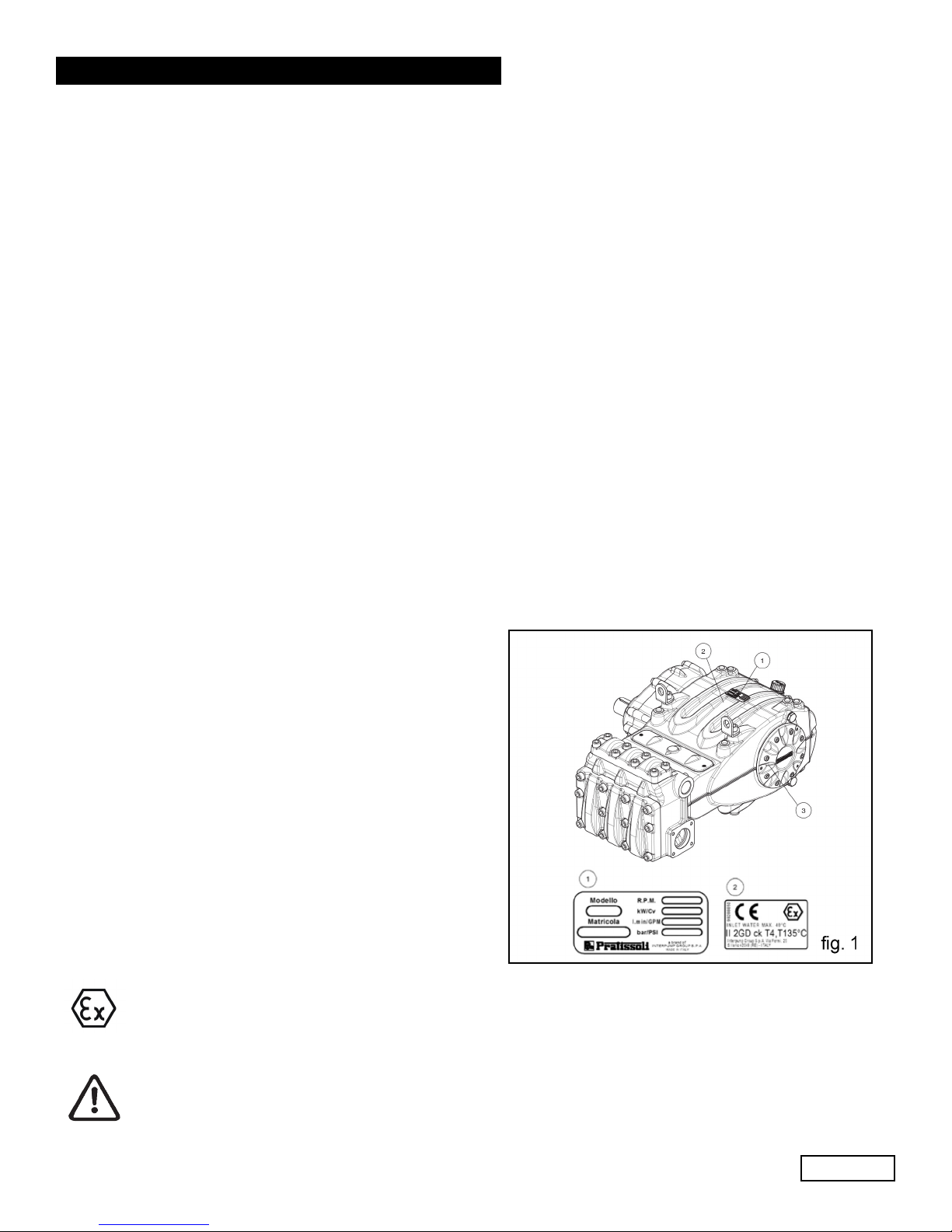
4. PUMP IDENTIFICATION
Each pump has a specific label (1, fig. 1) which contains:
Pump model and version
Serial Number
Maximum RPM
Power Hp-kW
Presure - P.S.I.
Flow Rate - GPM
For pumps ordered with the ATEX configuration.
(2, fig. 1) With specific ATEX marking for explosion
protection.
(3, fig. 1) For locating the grounding screw.
Pump model, version and serial number must always
be specified when ordering spare parts.
Ref 310069 Rev. B
07-18
Page 5
GENERAL PUMP
A member of the Interpump Group
5. TECHNICAL FEATURES
MF SERIES
MODEL RPM
800
1500
MF 45
MF 50
MF 55
1800
2200
2600
800
1500
1800
2200
2600
800
1500
1800
2200
2600
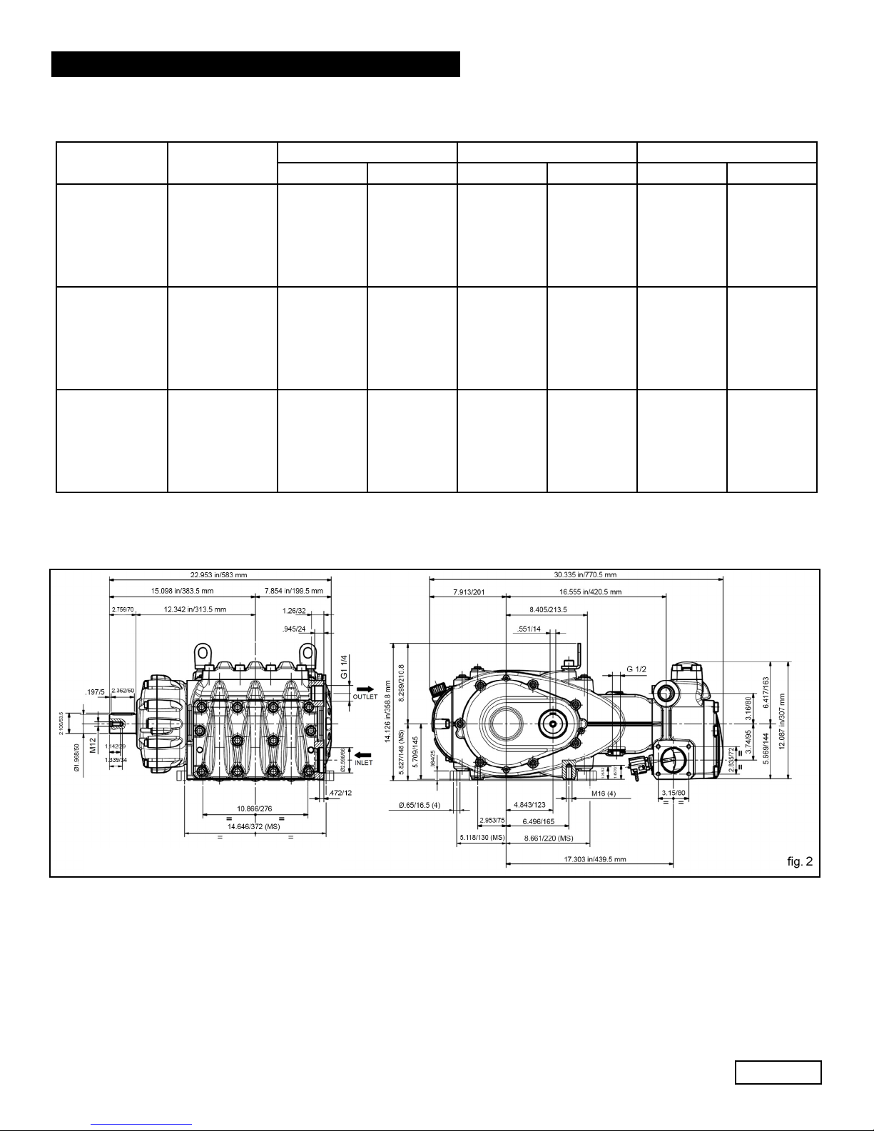
6. DIMENSIONS AND WEIGHT
FLOW RATE PRESSURE POWER
l/min GPM PSI Bar Hp kW
267
267
269
270
270
330
330
332
333
333
399
399
401
403
403
70.6
70.6
71
71.3
71.3
87.2
87.2
87.6
88
88
105.4
105.4
106
106.5
106.5
2900 200
2465 170
2032 140
139
139
140
140
140
146
146
147
147
147
147
145
145
146
147
147
102.2
102.2
102.9
102.9
102.9
107.3
107.3
108.1
108.1
108.1
106.6
106.6
107.3
108.1
108.1
Weight: 551 Lbs./250 Kg.
Ref 310069 Rev. B
07-18
Page 6
GENERAL PUMP
A member of the Interpump Group
7.INFORMATION ABOUT PUMP USE
The MF pump, when not ordered with the ATEX configuration, is designed to operate in environments with
atmosphers that are not potentially explosive, and with filtered water (see par. 9.7)
Other fluids may be used only upon the approval of The Customer Service Department.
MF SERIES
7.1 WaterTemperature
The max water temperature is 104
of up to 1400F (600C) for short periods of time. In this case we advise consulting the Customer Service
Department.
7.2 Max Pressure and Flow Rate
The performance values indicated in the catalog refer to the maximum performance of the pump. Regardless of the power
used, pressure and maximum RPM values indicated on the plate may not be exceeded unless expressly authorized by the
Customer Service Department.
7.3 Minimum Operating Speed
The minimum speed of the crankshaft for these types of pumps is 300 RPM. Any RPM value different from what is
indicated in the performance table (see chapter 5) must be expressly authorized by the Customer Service Department.
7.4
Recommended Lubricant Oil Types & Manufacturers
The pump is delivered with lubricant oil compliant with room temperatures ranging between 32
300C ). Some recommended lubricant types are indicated in the table below; these lubricants are treated with additives
in order to increase corrosion protection and resistance to fatigue. As an alternative, Automotive SAE 85W-90 gearing
lubricants may also be used.
BRAND TYPE
GENERAL PUMP SERIES 220
ARAL Aral Degol BG 220
BP ENERGOL HLP 220
CASTROL Hyspin VG 220, Magna 220
ELF
ESSO NUTO 220
FINA Cirkan 220
FUCHS RENOLIN 220
MOBIL DTE OIL BB
SHELL TELLUS C 220
TEXACO RANDO HD 220
TOTAL CORTIS 220
POLYTELIS 220
0
F (40
0
C).However, it is possible to use the pump at temperatures
0
and 89.60 F (00 and
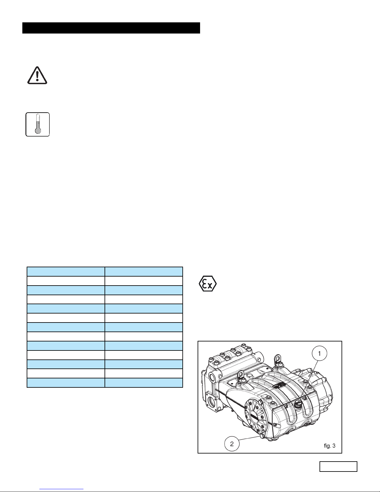
Set up the pump so that the oil temperature
does not exceed in any case 212°F (100°C)
during pump operation.
Use a temperature probe to be inserted into
the oil drain plug (2, fig. 3). See the “ATEX
EXPLOSION PROTECTION” manual.
ATTENTION: Use only oil with flash point
higher than 392°F (200°C).
Check the oil level by using the oil level dipstick (1, fig.
3). Refill if necessary to top off level. Correct oil level
inspection is done with the pump at room temperature;
oil is changed with the pump at working temperature, by
removing the rear plug (2, fig. 3).
Checking and changing oil is to be carried out as indicated
in Chapter 11. The amount required is 287 oz. (8.5 liters)
for pumps with reduction units and 253 oz (7.5 liters) for
pumps with no reduction units.
Ref 310069 Rev. B
07-18
Page 7
 Loading...