

Page 1

Messerschleifer
Betriebsanleitung
Knife sharpener
Operating Instructions
Affûteur
Manuel d'utilisation
Knivsliper
Bruksanvisning
Knivslipmaskin
Bruksanvisning
Afiladora de cuchillas
Instrucciones de servicio
MS100 04
Vor Beginn aller Arbeiten Betriebsanleitung lesen!
Read the operating instructions before commencing any work!
Avant tous les travaux, lire les instructions de service!
Bruksanvisningen må leses før arbeidet påbegynnes!
Läs alltid igenom bruksanvisningen, innan något arbete påbörjas!
¡Léanse las instrucciones de servicio antes de proceder con cualquier trabajo!
MS 100
Deutsch
EnglishFrançais
NorskSvenskEspañol
Page 2

© Göweil Maschinenbau GmbH
Eben 128
4202 Kirchschlag
Österreich
Tel.: +43 (0) 7215 / 2131-0
Fax: +43 (0) 7215 / 21319
Release: 2009-01-001
Erstellt durch:
INDEMA
www.indema.at
Page 3

Betriebsanleitung
Messerschleifer
MS 100
Page 4

EG-
Konformitätserklärung
entsprechend der EG
GÖWEIL MASCHINENBAU GMBH
( Name des Anbieters)
A-
4202 Kirchschlag, Eben 128
(vollständige Anschrift der Firma-
bei in der Gemeinschaft niedergelassenen Bevollmächtigten ebenfalls
der Firma und Anschrift des Herstellers)
erklärt in alleiniger Verantwortung, dass das Produkt
Messerschleifer MS 100
(Fabrikat, Type)
auf das sich diese Erklärung bezieht, den einschlägigen grundlegenden Sicherheits
und Gesundhe
itsanforderungen der EG
(falls zutreffend)
sowie den Anforderunge
n der anderen einschlägigen EG
98/37/EG Maschinenrichtlinie,
2006/42/EG
Maschinenrichtlinie,
Bundesgesetzblatt I
Nr. 8/2008 in der gültigen Fassung
2006/95/EG
Niederspannungsrichtlinie
(Titel und / oder Nummer sowie Ausgabedatum der anderen EG
entspricht.
(falls zutreffend)
Zur sachgerechten Umsetzung der in den EG
und Gesundheitsanforderungen wurde(n)
technische Spezifikation(en)
(jeweils letztgültige Fassung)
EN 294; EN 349; EN 547
-
EN ISO 13849 – 1; EN 9
99
EN ISO 14121;
EN 60204
(Titel
und / oder Nummer sowie Ausgabedatum der Norm(en) und / oder der technischen Spezifikation(en))
Kirchschlag, 10.03.2009
(Ort und Datum der Ausstellung)
-Richtlinie 98/37/EG
-Richtlinie 98/37/EG,
-Richtlinien
Anhang 1
umgesetzt in Österreich durch
- Richtlinien)
- Richtlinien genannten Sicherheits
-
folgende Norm(en) und/ oder
herangezogen:
1; EN 614-1; EN 563; EN 894; EN 953;
; EN 1037; EN ISO 12100; EN 13850;
-1
Herbert Göweil, Geschäftsführer
(Name, Funktion und Unterschrift des Befugten)
Angabe
-
Page 5

22
Messerschleifer MS 100
Inhaltsverzeichnis
10.03.2009 1
1 Allgemeines .................................................................................................. 3
1.1 Informationen zu dieser Anleitung ...................................................... 3
1.2 Symbolerklärung ................................................................................ 3
1.3 Haftungsbeschränkung ...................................................................... 4
1.4 Urheberschutz ................................................................................... 4
1.5 Ersatzteile .......................................................................................... 4
1.6 Garantiebestimmungen ...................................................................... 4
1.7 Kundendienst ..................................................................................... 4
2 Sicherheit ...................................................................................................... 5
2.1 Bestimmungsgemäße Verwendung ................................................... 5
2.2 Verantwortung des Betreibers ............................................................ 5
2.3 Personalanforderungen ..................................................................... 6
2.4 Persönliche Schutzausrüstung ........................................................... 7
2.5 Besondere Gefahren.......................................................................... 8
2.6 Sicherheitseinrichtungen .................................................................... 9
2.7 Sichern gegen Wiedereinschalten .................................................... 10
2.8 Verhalten im Gefahrenfall und bei Unfällen ...................................... 10
2.9 Umweltschutz .................................................................................. 10
2.10 Beschilderung .................................................................................. 11
2.11 Warnzeichen .................................................................................... 11
2.12 Modifikationen ................................................................................. 11
3 Technische Daten ...................................................................................... 12
3.1 Allgemeine Angaben ........................................................................ 12
3.2 Anschlusswerte................................................................................ 12
3.3 Betriebsbedingungen ....................................................................... 13
3.4 Emissionen ...................................................................................... 13
3.5 Betriebsstoffe ................................................................................... 13
3.6 Typenschild ..................................................................................... 13
4 Aufbau und Funktion ................................................................................. 14
4.1 Übersicht ......................................................................................... 14
4.2 Kurzbeschreibung ............................................................................ 14
4.3 Anschlüsse ...................................................................................... 15
4.4 Arbeits- und Gefahrenbereiche ........................................................ 15
4.5 Lage der Not-Aus-Taster ................................................................. 16
4.6 Bedienelemente ............................................................................... 16
4.7 Betriebsarten ................................................................................... 16
5 Transport, Verpackung .............................................................................. 17
5.1 Transportinspektion ......................................................................... 17
5.2 Verpackung ..................................................................................... 17
6 Bedienung .................................................................................................. 17
6.1 Sicherheit......................................................................................... 17
6.2 Erstinbetriebnahme .......................................................................... 18
6.3 Vorbereitungen ................................................................................ 19
6.4 Bogenmesser positionieren .............................................................. 19
6.5 Schleifeinheit einstellen ................................................................... 20
6.6 Schleifwinkel einstellen .................................................................... 21
6.7 Drehbegrenzer einstellen ................................................................. 21
Page 6

Messerschleifer MS 100
Inhaltsverzeichnis
2 10.03.2009
6.8 Betrieb ............................................................................................ 22
6.9 Abstellen der Maschine ................................................................... 23
6.10 Linearschleifeinheit (Zusatzausrüstung) .......................................... 23
6.11 Messer für Rundballenpresse Krone VP 1500 und VP 1800
positionieren .................................................................................... 24
7 Störungen .................................................................................................. 25
7.1 Sicherheit ........................................................................................ 25
7.2 Störungstabelle ............................................................................... 26
7.3 Störungsbehebung .......................................................................... 26
8 Instandhaltung ........................................................................................... 27
8.1 Sicherheit ........................................................................................ 27
8.2 Wartungsplan .................................................................................. 28
8.3 Wartungsarbeiten ............................................................................ 28
8.4 Schmierplan .................................................................................... 29
8.5 Maßnahmen nach erfolgter Wartung ............................................... 29
9 Demontage ................................................................................................. 29
9.1 Entsorgung ...................................................................................... 29
10 Ersatzteile .................................................................................................. 30
10.1 Ersatzteilbestellung ......................................................................... 30
11 Anhang ....................................................................................................... 30
11.1 Fremdunterlagen ............................................................................. 30
11.2 Ersatzteillisten / Montagelisten / Schaltpläne ................................... 30
Page 7
22
Messerschleifer MS 100
Allgemeines
10.03.2009 3
1 Allgemeines
Pos: 1.2 /KN2006-SM/Allgemeines/110 1.1 Informatione n zur Anleitung (A nlage) @ 9\mo d_114440275 0137_1.doc @ 8 6521
1.1 Informationen zu dieser Anleitung
Diese Anleitung ermöglicht den sicheren und effizienten Umgang mit der Maschine.
Die Anleitung ist Bestandteil der Maschine und muss in unmittelbarer Nähe der Maschine für das Personal
jederzeit zugänglich aufbewahrt werden. Das Personal muss diese Anleitung vor Beginn aller Arbeiten sorgfältig
durchgelesen und verstanden haben. Grundvoraussetzung für sicheres Arbeiten ist die Einhaltung aller
angegebenen Sicherheitshinweise und Handlungsanweisungen in dieser Anleitung.
Darüber hinaus gelten die örtlichen Unfallverhütungsvorschriften und allgemeinen Sicherheitsbestimmungen für
den Einsatzbereich der Maschine.
Abbildungen in dieser Anleitung dienen dem grundsätzlichen Verständnis und können von der tatsächlichen
Ausführung der Maschine abweichen.
Neben dieser Anleitung gelten die im Anhang befindlichen Anleitungen der verbauten Komponenten.
1.2 Symbolerklärung
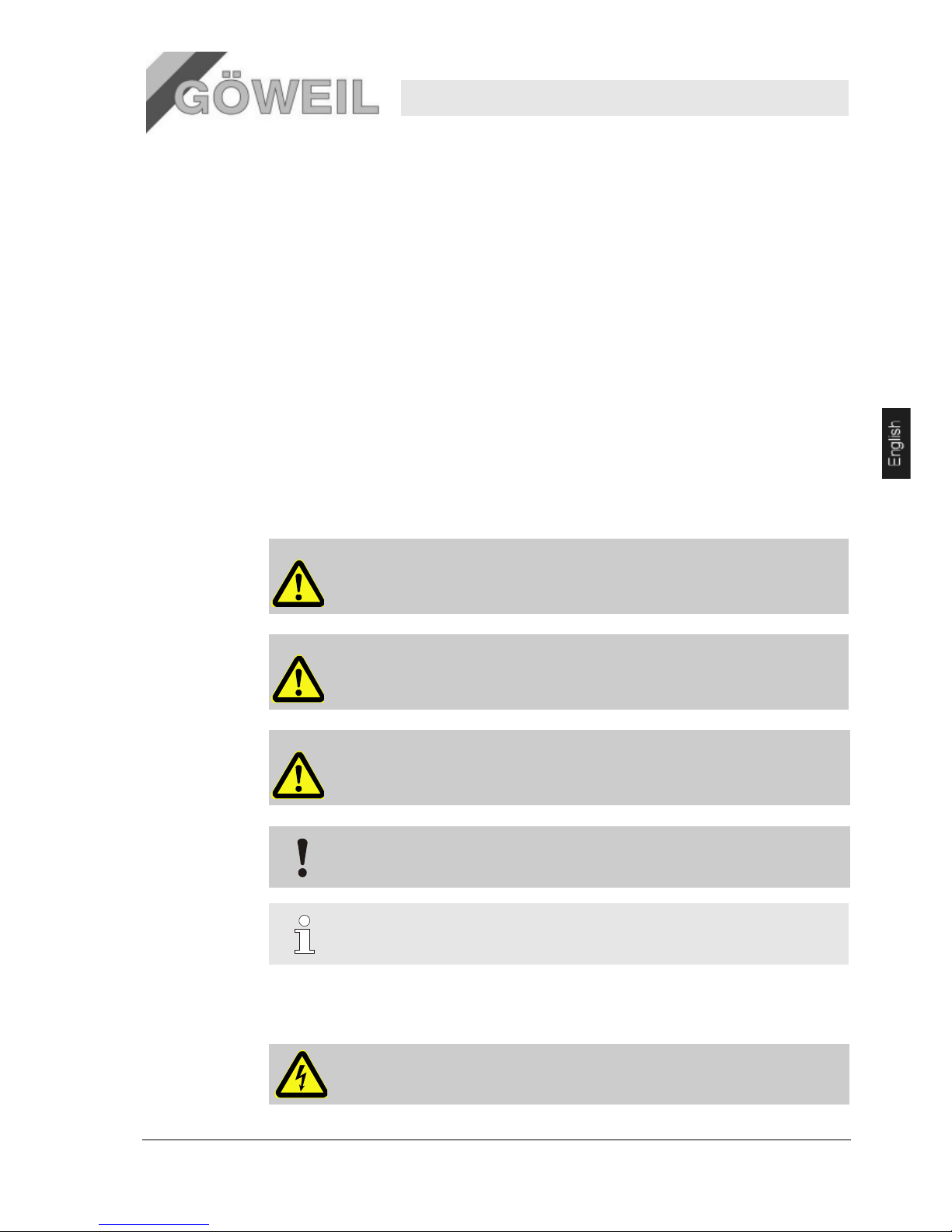
Sicherheitshinweise
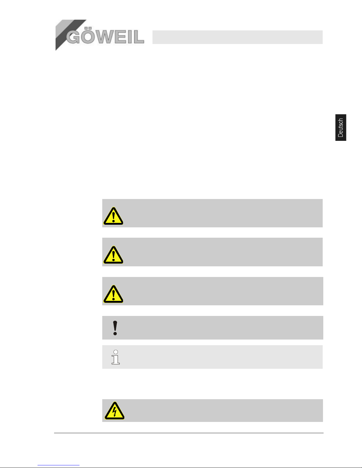
Sicherheitshinweise sind in dieser Anleitung durch Symbole gekennzeichnet. Die Sicherheitshinweise
werden durch Signalworte eingeleitet, die das Ausmaß der Gefährdung zum Ausdruck bringen.
Sicherheitshinweise unbedingt einhalten und umsichtig handeln, um Unfälle, Personen- und
Sachschäden zu vermeiden.
GEFAHR!
… weist auf eine unmittelbar gefährliche Situation hin, die zum Tod oder zu schweren
Verletzungen führt, wenn sie nicht gemieden wird.
WARNUNG!
… weist auf eine möglicherweise gefährliche Situation hin, die zum Tod oder zu schweren
Verletzungen führen kann, wenn sie nicht gemieden wird.
VORSICHT!
… weist auf eine möglicherweise gefährliche Situation hin, die zu geringfügigen oder leichten
Verletzungen führen kann, wenn sie nicht gemieden wird.
VORSICHT!
… weist auf eine möglicherweise gefährliche Situation hin, die zu Sachschäden führen kann,
wenn sie nicht gemieden wird.
Tipps und
Empfehlungen
HINWEIS!
… hebt nützliche Tipps und Empfehlungen sowie Informationen für einen effizienten und
störungsfreien Betrieb hervor.
Besondere
Sicherheitshinweise
Um auf besondere Gefahren aufmerksam zu machen, werden in Sicherheitshinweisen folgende
Symbole eingesetzt:
… kennzeichnet Gefährdungen durch elektrischen Strom. Bei Nichtbeachtung der
Sicherheitshinweise besteht die Gefahr schwerer oder tödlicher Verletzungen.
Page 8

Messerschleifer MS 100
Allgemeines
4 10.03.2009
1.3 Haftungsbeschränkung
Alle Angaben und Hinweise in dieser Anleitung wurden unter Berücksichtigung der geltenden Normen und
Vorschriften, des Stands der Technik sowie unserer langjährigen Erkenntnisse und Erfahrungen
zusammengestellt.
Der Hersteller übernimmt keine Haftung für Schäden aufgrund:
Nichtbeachtung der Anleitung
Nichtbestimmungsgemäßer Verwendung
Einsatz von nicht ausgebildetem Personal
Eigenmächtiger Umbauten
Technischer Veränderungen
Verwendung nicht zugelassener Ersatzteile
Der tatsächliche Lieferumfang kann bei Sonderausführungen, der Inanspruchnahme zusätzlicher
Bestelloptionen oder aufgrund neuester technischer Änderungen von den hier beschriebenen Erläuterungen
und Darstellungen abweichen.
Es gelten die im Liefervertrag vereinbarten Verpflichtungen, die Allgemeinen Geschäftsbedingungen sowie die
Lieferbedingungen des Herstellers und die zum Zeitpunkt des Vertragsabschlusses gültigen gesetzlichen
Regelungen.
Technische Änderungen im Rahmen der Verbesserung der Gebrauchseigenschaften und der
Weiterentwicklung behalten wir uns vor.
1.4 Urheberschutz
Diese Anleitung ist urheberrechtlich geschützt und ausschließlich für interne Zwecke bestimmt.
Überlassung der Anleitung an Dritte, Vervielfältigungen in jeglicher Art und Form – auch auszugsweise – sowie
Verwertung und/oder Mitteilung des Inhaltes sind ohne schriftliche Genehmigung des Herstellers außer für
interne Zwecke nicht gestattet.
Zuwiderhandlungen verpflichten zu Schadenersatz. Weitere Ansprüche bleiben vorbehalten.
Pos: 1.14 /KN2006-SM/nL--------- - Abschnittsende ------ ---- @ 8\mod_11 41997892953_0 .doc @ 75471
1.5 Ersatzteile
WARNUNG!
Sicherheitsrisiko durch falsche Ersatzteile!
Falsche oder fehlerhafte Ersatzteile können die Sicherheit beeinträchtigen sowie zu
Beschädigungen, Fehlfunktionen oder Totalausfall führen.
Deshalb:
– Nur Originalersatzteile des Herstellers verwenden.
Ersatzteile über Vertragshändler oder direkt beim Hersteller beziehen. Die Ersatzteilliste befindet sich im
Anhang.
1.6 Garantiebestimmungen
Pos: 1.19 /KN2006-SM/Allgemeines/161 1. 1.0 Garantieb estimmungen i n den AGB des H erstellers @ 9\mod_1144054 766031_1.doc @ 84763
Der Hersteller übernimmt eine Garantiezeit von max. 1 Jahr.
Pos: 1.20 /KN2006-SM/nL--------- - Abschnittsende ------ ---- @ 8\mod_11 41997892953_0 .doc @ 75471
1.7 Kundendienst
Für technische Auskünfte steht unser Kundendienst zur Verfügung. Darüber hinaus sind unsere Mitarbeiter
ständig an neuen Informationen und Erfahrungen interessiert, die sich aus der Anwendung ergeben und für die
Verbesserung unserer Produkte wertvoll sein können.
Page 9

22
Messerschleifer MS 100
Sicherheit
10.03.2009 5
2 Sicherheit
Pos: 2.3 /KN2006-SM/Sicherheit/001 1.0 Ein führung @ 8\ mod_1142427 208593_1.doc @ 77470
Dieser Abschnitt gibt einen Überblick über alle wichtigen Sicherheitsaspekte für einen optimalen Schutz des
Personals sowie für den sicheren und störungsfreien Betrieb.
Die Nichtbeachtung der in dieser Anleitung aufgeführten Handlungsanweisungen und Sicherheitshinweise kann
zu erheblichen Gefährdungen führen.
2.1 Bestimmungsgemäße Verwendung
Die Maschine ist ausschließlich für die hier beschriebene bestimmungsgemäße Verwendung konzipiert und
konstruiert.
Der Messerschleifer ist ausschließlich für das Schleifen von konkaven Bogenmessern, mit der
Zusatzausrüstung „Linearschleifeinheit“ auch für gerade Messer von landwirtschaftlichen Pressen und
Ladewagen bestimmt.
Jeder andere Verwendungszweck gilt NICHT als bestimmungsgemäß. Für daraus entstandene Schäden oder
Unfälle haftet der Hersteller NICHT!
Das Risiko trägt allein der Betreiber. Zur bestimmungsgemäßen Verwendung gehört auch die Einhaltung der
vom Hersteller vorgeschriebenen Betriebs-, Wartungs- und Instandhaltungsbedingungen.
WARNUNG!
Gefahr durch Fehlgebrauch!
Jede über die bestimmungsgemäße Verwendung hinausgehende oder andersartige
Benutzung der Maschine kann zu gefährlichen Situationen führen.
Deshalb:
– Maschine nur bestimmungsgemäß verwenden.
– Alle Angaben in dieser Betriebsanleitung strikt einhalten.
Insbesondere folgende Verwendungen der Maschine unterlassen:
– sämtliche Schleifarbeiten die nicht in die bestimmungsgemäße Verwendung fallen
Ansprüche jeglicher Art wegen Schäden aufgrund nicht bestimmungsgemäßer Verwendung sind
ausgeschlossen.
2.2 Verantwortung des Betreibers
Die Maschine wird im gewerblichen und privaten Bereich eingesetzt. Der gewerbliche Betreiber der Maschine
unterliegt daher den gesetzlichen Pflichten zur Arbeitssicherheit.
Neben den Sicherheitshinweisen in dieser Anleitung müssen die für den Einsatzbereich der Maschine gültigen
Sicherheits-, Unfallverhütungs- und Umweltschutzvorschriften eingehalten werden. Dabei gilt insbesondere:
Der Betreiber muss sich über die geltenden Arbeitsschutzbestimmungen informieren und in einer
Gefährdungsbeurteilung zusätzlich Gefahren ermitteln, die sich durch die speziellen Arbeitsbedingungen
am Einsatzort der Maschine ergeben. Diese muss er in Form von Betriebsanweisungen für den Betrieb der
Maschine umsetzen.
Der Betreiber muss während der gesamten Einsatzzeit der Maschine prüfen, ob die von ihm erstellten
Betriebsanweisungen dem aktuellen Stand der Regelwerke entsprechen und diese falls erforderlich
anpassen.
Der Betreiber muss die Zuständigkeiten für Installation, Bedienung, Wartung und Reinigung eindeutig
regeln und festlegen.
Der Betreiber muss dafür sorgen, dass alle Mitarbeiter, die mit der Maschine umgehen, die Anleitung
gelesen und verstanden haben.
Darüber hinaus muss er das Personal in regelmäßigen Abständen schulen und über die Gefahren informieren.
Der Betreiber muss dem Personal die erforderliche Schutzausrüstung bereitstellen.
Page 10

Messerschleifer MS 100
Sicherheit
6 10.03.2009
Weiterhin ist der Betreiber dafür verantwortlich, dass die Maschine stets in technisch einwandfreiem Zustand ist,
daher gilt Folgendes:
Der Betreiber muss dafür sorgen, dass die in dieser Anleitung beschriebenen Wartungsintervalle
eingehalten werden.
Der Betreiber muss alle Sicherheitseinrichtungen regelmäßig auf Funktionsfähigkeit und Vollständigkeit
überprüfen lassen.
Vor dem Transport muss die Maschine auf Transportsicherheit geprüft werden.
2.3 Personalanforderungen
2.3.1 Qualifikationen
WARNUNG!
Verletzungsgefahr bei unzureichender Qualifikation!
Unsachgemäßer Umgang kann zu erheblichen Personen- und Sachschäden führen.
Deshalb:
– Alle Tätigkeiten nur durch dafür qualifiziertes Personal durchführen lassen.
In der Betriebsanleitung werden folgende Qualifikationen für verschiedene Tätigkeitsbereiche benannt.
Unterwiesene Person
wurde in einer Unterweisung durch den Hersteller über die ihr übertragenen Aufgaben und möglichen
Gefahren bei unsachgemäßem Verhalten unterrichtet.
Fachpersonal
ist aufgrund seiner fachlichen Ausbildung, Kenntnisse und Erfahrung sowie Kenntnis der einschlägigen
Bestimmungen in der Lage, die ihm übertragenen Arbeiten auszuführen und mögliche Gefahren
selbstständig zu erkennen und zu vermeiden.
Elektrofachkraft
ist aufgrund ihrer fachlichen Ausbildung, Kenntnisse und Erfahrungen sowie Kenntnis der einschlägigen
Normen und Bestimmungen in der Lage, Arbeiten an elektrischen Anlagen auszuführen und mögliche
Gefahren selbstständig zu erkennen und zu vermeiden.
Die Elektrofachkraft ist für den speziellen Einsatzort, in dem sie tätig ist, ausgebildet und kennt die
relevanten Normen und Bestimmungen.
Als Personal sind nur Personen zugelassen, von denen zu erwarten ist, dass sie ihre Arbeit zuverlässig
ausführen. Personen unter 16 Jahren oder Personen, deren Reaktionsfähigkeit beeinflusst ist, z. B. durch
Drogen, Alkohol oder Medikamente, sind nicht zugelassen.
Bei der Personalauswahl die am Einsatzort geltenden alters- und berufsspezifischen Vorschriften beachten.
2.3.2 Unbefugte
WARNUNG! Gefahr für Unbefugte!
Unbefugte Personen, die die hier beschriebenen Anforderungen nicht erfüllen, kennen die
Gefahren im Arbeitsbereich nicht.
Deshalb:
– Unbefugte Personen vom Arbeitsbereich fernhalten.
– Im Zweifel Personen ansprechen und sie aus dem Arbeitsbereich weisen.
– Die Arbeiten unterbrechen, solange sich Unbefugte im Arbeitsbereich aufhalten.
Page 11
22
Messerschleifer MS 100
Sicherheit
10.03.2009 7
2.3.3 Unterweisung
Das Personal muss regelmäßig vom Betreiber unterwiesen werden. Zur besseren Nachverfolgung muss die
Durchführung der Unterweisung protokolliert werden.
Datum Name Art der Unterweisung Unterweisung erfolgt durch Unterschrift
2.4 Persönliche Schutzausrüstung
Bei der Arbeit ist das Tragen von persönlicher Schutzausrüstung erforderlich, um die Gesundheitsgefahren zu
minimieren.
Die für die jeweilige Arbeit notwendige Schutzausrüstung während der Arbeit stets tragen.
Im Arbeitsbereich angebrachte Hinweise zur persönlichen Schutzausrüstung befolgen.
Pos: 2.22 /KN2006-SM/Sicherheit/006 Pers önliche Schutza usstattung/ 006 1.1.0_1 Gru ndsätzlich zu trag en_Titel @ 8\ mod_1143360 998458_1.doc @ 80989
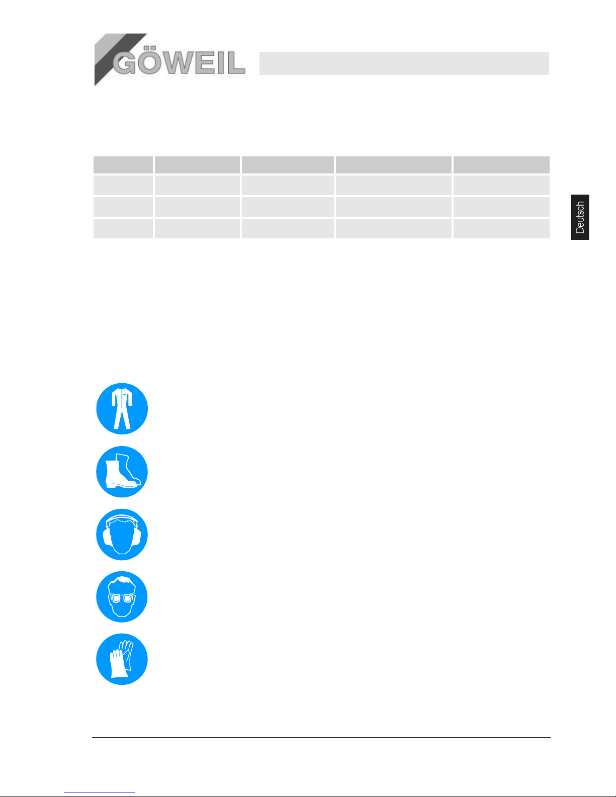
Grundsätzlich tragen:
Bei allen Arbeiten grundsätzlich tragen:
Arbeitsschutzkleidung
ist eng anliegende Arbeitskleidung mit geringer Reißfestigkeit, mit engen Ärmeln und ohne abstehende Teile.
Sie dient vorwiegend zum Schutz vor Erfassen durch bewegliche Maschinenteile.
Keine Ringe, Ketten und sonstigen Schmuck tragen.
Sicherheitsschuhe
zum Schutz vor schweren herabfallenden Teilen und Ausrutschen auf rutschigem Untergrund.
Gehörschutz
zum Schutz vor Gehörschäden.
Schutzbrille
zum Schutz der Augen vor umherfliegenden Teilen, Flüssigkeitsspritzern und Schleifspritzern.
Schutzhandschuhe
zum Schutz der Hände vor Reibung, Abschürfungen, Einstichen, Schnitten oder tieferen Verletzungen sowie
vor Berührung mit heißen Oberflächen.
Page 12

Messerschleifer MS 100
Sicherheit
8 10.03.2009
Pos: 2.27 /KN2006-SM/Sicherheit/006 Pers önliche Schutza usstattung/ 006 1.1.0_2 Bei b esonderen Ar beiten zu tragen _Titel @ 8\mo d_114336112 2656_1.doc @ 8 0999
2.5 Besondere Gefahren
Im folgenden Abschnitt sind Restrisiken benannt, die aufgrund einer Risikobeurteilung ermittelt wurden.
Die hier aufgeführten Sicherheitshinweise und die Warnhinweise in den weiteren Kapiteln dieser
Anleitung beachten, um Gesundheitsgefahren zu reduzieren und gefährliche Situationen zu vermeiden.
Bewegte
Bauteile
WARNUNG!
Verletzungsgefahr durch bewegte Bauteile!
Rotierende und/oder linear bewegte Bauteile können schwere Verletzungen verursachen.
Deshalb:
– Während des Betriebs nicht in bewegte Bauteile eingreifen oder an bewegten Bauteilen
hantieren.
– Abdeckungen im Betrieb nicht öffnen.
– Nachlaufzeit beachten:
Vor dem Wechseln der zu schleifenden Messer sicherstellen, dass sich keine Teile
mehr bewegen.
– Im Gefahrenbereich eng anliegende Arbeitsschutzkleidung tragen.
Lärm
WARNUNG!
Gehörschädigung durch Lärm!
Der im Arbeitsbereich auftretende Lärmpegel kann schwere Gehörschädigungen
verursachen.
Deshalb:
– Bei Arbeiten grundsätzlich Gehörschutz tragen.
– Nur soweit erforderlich im Gefahrenbereich aufhalten.
Heiße
Oberflächen
VORSICHT!
Verbrennungsgefahr durch heiße Oberflächen!
Kontakt mit heißen Bauteilen kann Verbrennungen verursachen.
Die neu geschliffenen Messer sind an der Schleifstelle sehr heiß!
Deshalb:
– Bei allen Arbeiten in der Nähe von heißen Bauteilen grundsätzlich Arbeits-
schutzkleidung und Schutzhandschuhe tragen.
– Vor allen Arbeiten sicherstellen, dass alle Bauteile auf Umgebungstemperatur abgekühlt
sind.
Federspannung
VORSICHT!
Verletzungsgefahr durch brechen der Federn!
Unter Spannung stehende Federn können zu Verletzungen führen.
Deshalb:
– Bei Arbeiten an unter Federspannung stehende Hebel vorsichtig vorgehen.
– Ausreichenden Sicherheitsabstand einhalten.
Scharfe
Kanten und
spitze Ecken
VORSICHT!
Verletzungsgefahr an Kanten und Ecken!
Scharfe Kanten und spitze Ecken an der Maschine können an der Haut Abschürfungen und
Schnitte verursachen.
Deshalb:
– Bei Arbeiten in der Nähe von scharfen Kanten und spitzen Ecken vorsichtig vorgehen.
– Im Zweifel Schutzhandschuhe tragen.
Page 13

22
Messerschleifer MS 100
Sicherheit
10.03.2009 9
Schmutz und
herumliegende
Gegenstände
VORSICHT!
Stolpergefahr durch Schmutz und herumliegende Gegenstände!
Verschmutzungen und herumliegende Gegenstände bilden Rutsch- und Stolperquellen und
können erhebliche Verletzungen verursachen.
Deshalb:
– Arbeitsbereich immer sauber halten.
– Nicht mehr benötigte Gegenstände entfernen.
2.6 Sicherheitseinrichtungen
WARNUNG!
Lebensgefahr durch nicht funktionierende Sicherheitseinrichtungen!
Die Sicherheit ist nur bei intakten Sicherheitseinrichtungen gewährleistet.
Deshalb:
– Vor Arbeitsbeginn prüfen, ob die Sicherheitseinrichtungen funktionstüchtig und richtig
installiert sind.
– Sicherheitseinrichtungen niemals außer Kraft setzen.
– Sicherheitsbauteile dürfen nicht überbrückt oder verändert werden.
– Sicherstellen, dass Sicherheitseinrichtungen wie Not-Aus-Taster, Reißleinen etc. stets
zugänglich sind.
HINWEIS!
Nähere Informationen zur Lage der Sicherheitseinrichtungen siehe Kapitel „Aufbau und
Funktion“.
Folgende Sicherheitseinrichtungen sind installiert:
Not-Aus-Taster
Durch Druck auf den Not-Aus-Taster wird ein Not-Stopp ausgelöst.
Nachdem ein Not-Aus-Taster gedrück
t wurde, muss dieser durch Schieben entriegelt werden, damit ein
Wiedereinschalten möglich ist.
WARNUNG!
Lebensgefahr durch unkontrolliertes Wiedereinschalten!
Unkontrolliertes Wiedereinschalten kann zu schweren Personenschäden oder zum
Tod führen!
Deshalb:
– Vor dem Wiedereinschalten sicherstellen, dass die Ursache für den Not-Stopp
beseitigt wurde, alle Sicherheitseinrichtungen montiert und funktionstüchtig sind.
– Den Not-Aus-Taster erst entriegeln, wenn keine Gefahr mehr besteht.
Sicherheitsschalter (Not-Aus)
Der Sicherheitsschalter befindet sich vorne auf dem Elektromotor.
Page 14

Messerschleifer MS 100
Sicherheit
10 10.03.2009
2.7 Sichern gegen Wiedereinschalten
GEFAHR!
Lebensgefahr durch unbefugtes Wiedereinschalten!
Bei Arbeiten im Gefahrenbereich besteht die Gefahr, dass die Energieversorgung unbefugt
eingeschaltet wird. Dadurch besteht Lebensgefahr für die Personen im Gefahrenbereich.
Deshalb:
– Die Hinweise zum Sichern gegen Wiedereinschalten in den Kapiteln dieser Anleitung
beachten.
– Immer den unten beschriebenen Ablauf zum Sichern gegen Wiedereinschalten
beachten.
Die Energieversorgung der Maschine erfolgt ausschließlich über eine Netzleitung und den
(länderspezifischen) Stecker.
Wahlweise mit 400V oder 230V Elektromotor.
Sichern gegen Wiedereinschalten:
1. Not-Aus Taste drücken bis diese einrastet.
2. weitere Arbeiten nur in diesem Zustand durchführen
2.8 Verhalten im Gefahrenfall und bei Unfällen
Vorbeugende
Maßnahmen
Stets auf Unfälle oder Feuer vorbereitet sein!
Erste-Hilfe-Einrichtungen (Verbandkasten, Decken usw.) und Feuerlöscher griffbereit aufbewahren.
Personal mit Unfallmelde-, Erste-Hilfe- und Rettungseinrichtungen vertraut machen.
Zufahrtswege für Rettungsfahrzeuge frei halten.
Maßnahmen bei
Unfällen
Not-Aus sofort auslösen.
Erste-Hilfe-Maßnahmen einleiten.
Personen aus der Gefahrenzone bergen.
Verantwortlichen am Einsatzort informieren.
Rettungsdienst alarmieren.
Zufahrtswege für Rettungsfahrzeuge frei machen.
2.9 Umweltschutz
VORSICHT!
Umweltgefahr durch falschen Umgang mit umweltgefährdenden Stoffen!
Bei falschem Umgang mit umweltgefährdenden Stoffen, insbesondere bei falscher Entsorgung,
können erhebliche Schäden für die Umwelt entstehen.
Deshalb:
– Die unten genannten Hinweise immer beachten.
– Wenn umweltgefährdende Stoffe versehentlich in die Umwelt gelangen, sofort geeignete
Maßnahmen ergreifen. Im Zweifel die zuständige Kommunalbehörde über den Schaden
informieren.
Folgende umweltgefährdende Stoffe werden verwendet:
Schmierstoffe
Schmierstoffe wie Fette und Öle enthalten giftige Substanzen. Sie dürfen nicht in die Umwelt gelangen. Die
Entsorgung muss durch einen Entsorgungs-Fachbetrieb erfolgen.
Page 15
22
Messerschleifer MS 100
Sicherheit
10.03.2009 11
2.10 Beschilderung
Die folgenden Symbole und Hinweisschilder befinden sich im Arbeitsbereich. Sie beziehen sich auf die
unmittelbare Umgebung, in der sie angebracht sind.
WARNUNG!
Verletzungsgefahr durch unleserliche Symbole!
Im Laufe der Zeit können Aufkleber und Schilder verschmutzen oder auf andere Weise
unkenntlich werden.
Deshalb:
– Alle Sicherheits-, Warn- und Bedienungshinweise in stets gut lesbarem Zustand halten.
– Beschädigte Schilder oder Aufkleber sofort erneuern.
2.11 Warnzeichen
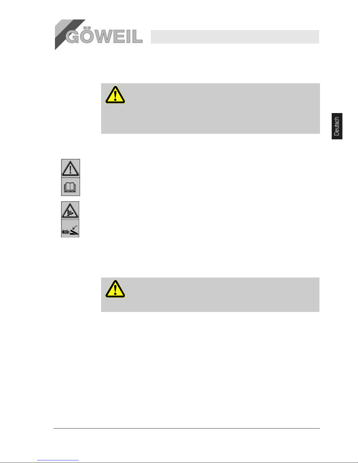
Betriebsanleitung beachten
Den gekennzeichneten Gegenstand erst benutzen, nachdem die Betriebsanleitung gelesen wurde.
Quetschgefahren
Warnung vor Quetschgefahren an einem Arbeitsmittel (z. B. einer Maschine) oder an baulichen Einrichtungen
(z. B. Verdeckungen, Verkleidungen, Umwehrungen, Umzäunungen).
Bei Arbeiten an den gekennzeichneten Arbeitsplätzen ist eine erhöhte Aufmerksamkeit notwendig.
Niemals in den Quetschgefahrenbereich greifen, solange sich dort Teile bewegen können.
2.12 Modifikationen
WARNUNG!
Verletzungsgefahr durch nicht autorisierte Modifikationen!
Modifikationen an der Maschine im Sinne von An- und Umbauten, insbesondere solche,
welche die Sicherheit tangieren könnten, sind nur nach vorheriger Absprache und mit
schriftlicher Genehmigung des Herstellers zulässig!
Page 16

22
Messerschleifer MS 100
Technische Daten
12 10.03.2009
3 Technische Daten
3.1 Allgemeine Angaben
Angabe Wert Einheit
Gewicht 69 kg
Länge 930 mm
Breite 675 mm
Höhe 1455 mm
Ausführung Ohne Linearschleifeinheit
Angabe Wert Einheit
Gewicht 73 kg
Länge 1105 mm
Breite 675 mm
Höhe 1455 mm
Ausführung Mit Linearschleifeinheit
HINWEIS!
Die technischen Daten (Abmessungen, Gewichte, Leistungen usw.) den beiliegenden
Layoutplänen (Lieferzeichnungen) und Datenblättern entnehmen [→ Anhang].
3.2 Anschlusswerte
Pos: 3.6 /KN2006-Projekte/NSD Lift AG/Te chnische Date n/002 1.1.0 Anschl usswerte --> NSD Comfort @ 45\mod_11 87710014840 _1.doc @ 566 242
Elektrisch
Angabe (Version 400V) Wert Einheit
Spannung 400/230 V
Leistung 1,1 kW
Frequenz 50 Hz
Drehzahl 2835 U/min
Schutzart IP55
Elektrisch
Angabe (Version 230V) Wert Einheit
Spannung 230 V
Leistung 1,1 kW
Frequenz 50 Hz
Drehzahl 2835 U/min
Schutzart IP55
Page 17
10.03.2009
3.3 Betriebsbedingungen
Pos: 3.9 /KN2006-Projekte/NSD Lift AG/Tech nische Daten/003 1.1.0 Betriebsbe dingungen --> LSD Comfort @ 4 5\mod_11877 10247081_1.doc @ 566257
Dauer
Angabe
Maximale Betriebsdauer am Stück
3.4 Emissionen
Pos: 3.12 /KN2006-Projekte/NSD Lift AG/Techni sche Daten/00 5 1.1.0 Emissio nen --> LSD Comf ort @ 45\mod _1187711003739 _1.doc @ 566 337
Angabe
Lärmemission
(Leerlauf / Schleifen)
3.5 Betriebsstoffe
Betriebsstoff
Schmierfett
3.6 Typenschild
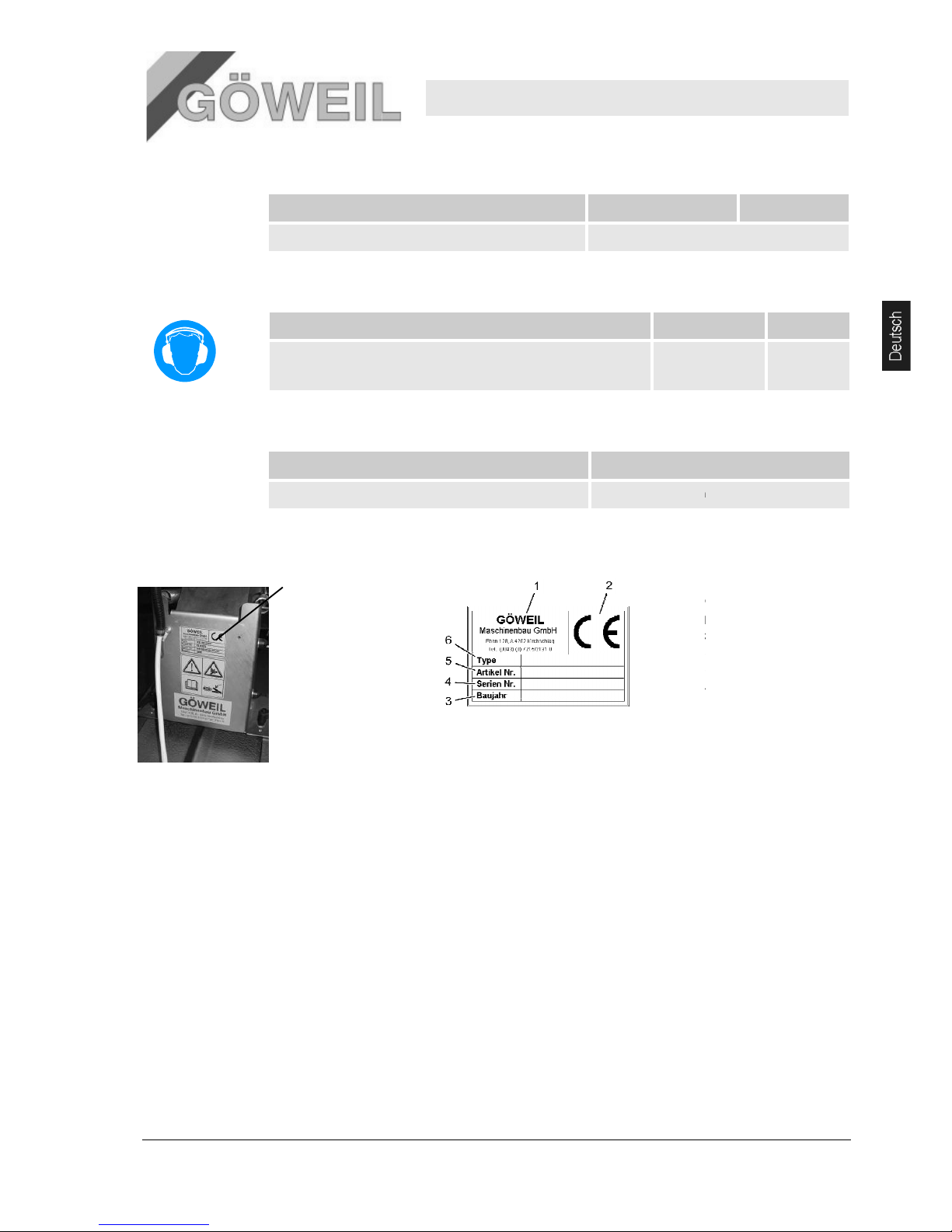
Das Typenschild befindet
sich auf der Rückseite
der Schleifeinheit.
Messerschleifer
Technische Daten
auf Dauerbetrieb ausgelegt
75-
80 / 102
Typ
lithiumverseiftes Mehrzweckfett NLGI
Das Typenschild beinhalt
folgende Angaben:
1
Hersteller
2
CE
3
Baujahr
4
Seriennummer
5
Artikelnummer
6
Typ
MS 100
13
Wert Einheit
Wert Einheit
-105 dB(A)
-Klasse 2
et
-Kennzeichnung
Page 18
Messerschleifer MS 100
Aufbau und Funktion
14 10.03.2009
4 Aufbau und Funktion
Pos: 4.3 /KN2006-SM/Aufbau und Funktio n/002 1.1 Üb ersicht_Titel @ 9\mod_11440 46023684_1.doc @ 84432
4.1 Übersicht
Pos: 4.4 /KN2006-Projekte/NSD Lift AG/A ufbau und Fun ktion/1.1 Übersic ht --> NSD C omfort @ 45\mo d_11876975851 02_1.doc @ 5 66022
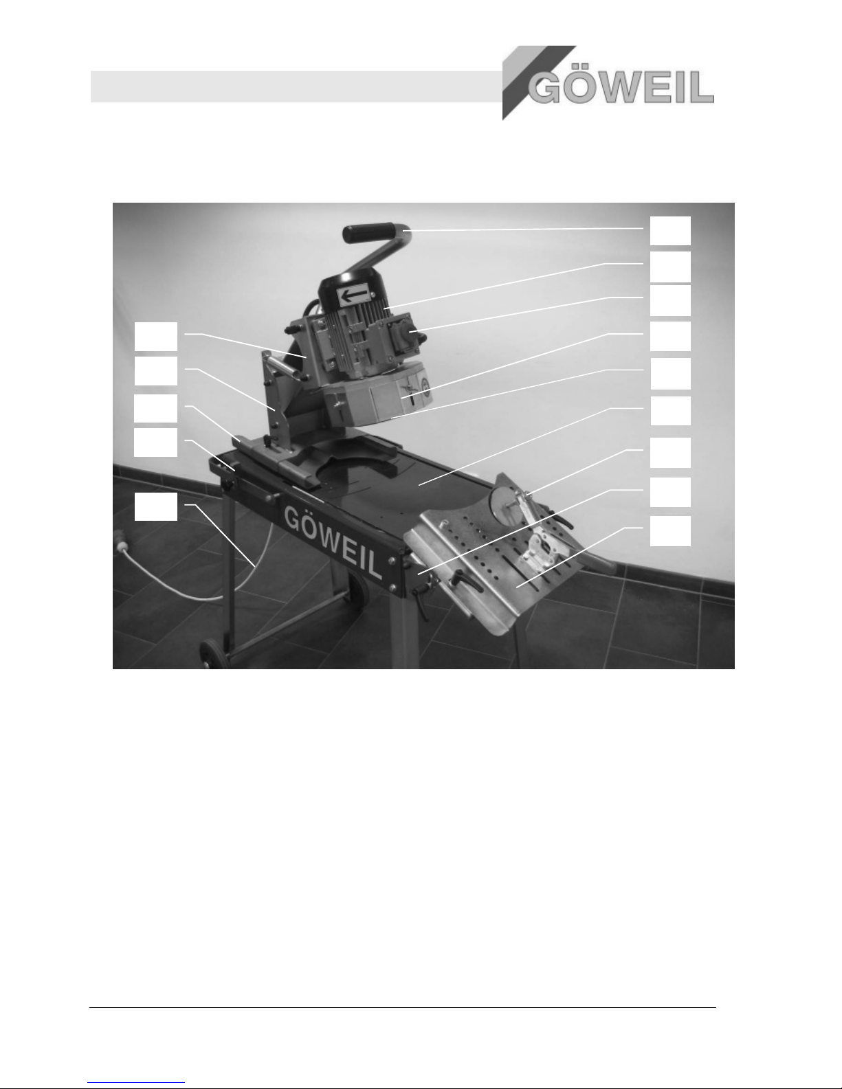
1 Bediengriff
2 Elektromotor
3 Ein – Aus Schalter mit NOT-AUS
4 Schutzblech (verstellbar)
5 Topfschleifscheibe
6 Schleiftisch
7 Spannvorrichtung
8 Linearschleifeinheit (Zusatzausrüstung)
9 Verstellblech
10 Motoraufnahme
11 Halteblech
12 Dreheinheit
13 Drehbegrenzer
14 Anschlusskabel
4.2 Kurzbeschreibung
Der Messerschleifer ist ausschließlich für das Schleifen von konkaven Bogenmessern, mit der
Zusatzausrüstung „Linearschleifeinheit“ auch für gerade Messer von landwirtschaftlichen
Pressen und Ladewagen bestimmt.
Das Messer wird auf das Verstellblech aufgelegt und mit der Spannvorrichtung befestigt. Dann
muss die Schleifeinheit auf dem Drehblech so eingestellt werden, dass man das Messer mit
dem entsprechenden Radius schleifen kann. Wenn dies alles erfolgt ist, kann das Messer
geschliffen werden.
2
3
4
5
6
7
8
9
10
Page 19
Messerschleifer MS 100
Aufbau und Funktion
10.03.2009 15
4.3 Anschlüsse
4.3.1 Elektroanschlüsse
Der Messerschleifer wird ohne Netzstecker geliefert. Daher muss der jeweils länderspezifische elektrische
Anschluss durch eine Elektrofachkraft erfolgen. Die Motordrehrichtung ist unbedingt zu beachten! Der
Stecker ist unbedingt nach dem beiliegenden Schaltplan anzuklemmen!
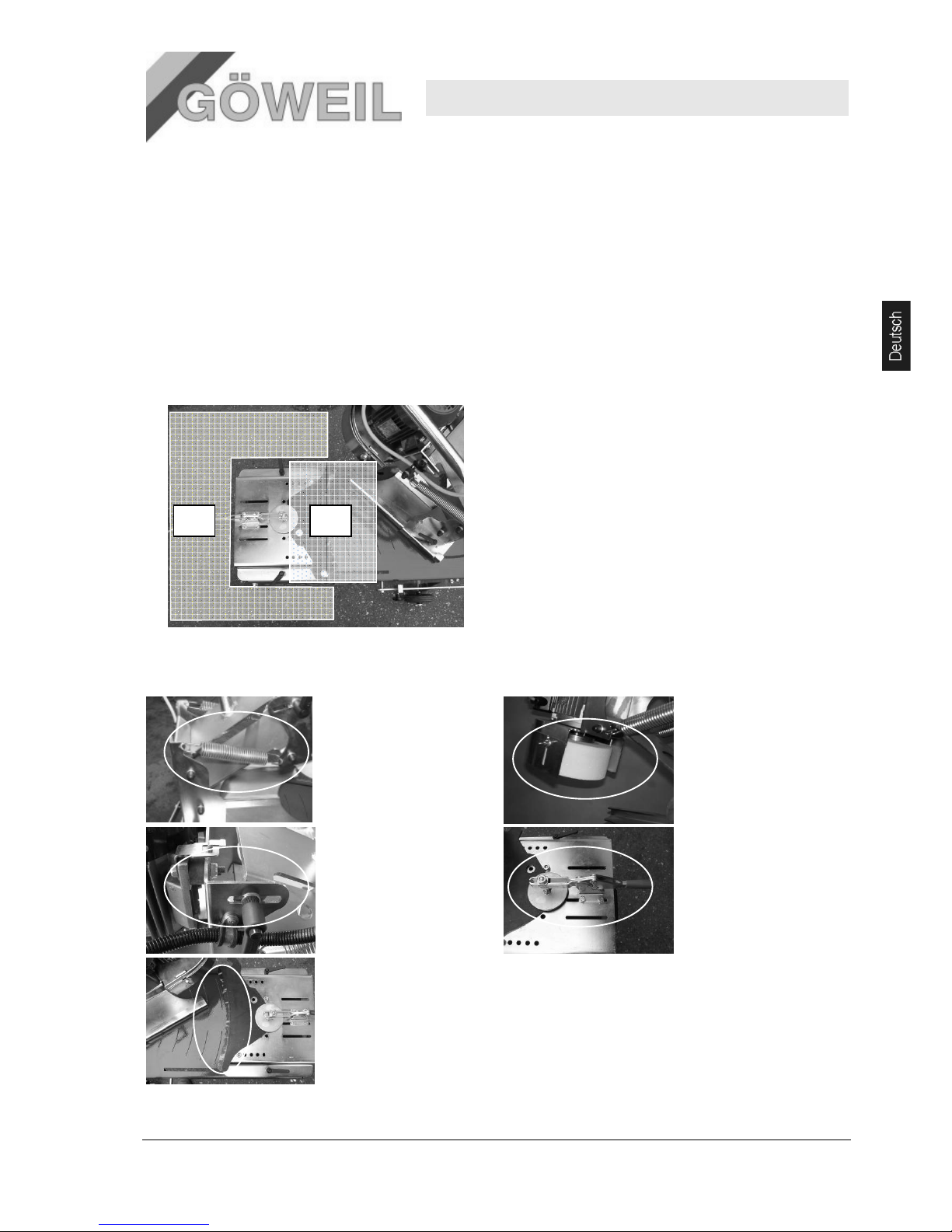
4.4 Arbeits- und Gefahrenbereiche
4.4.1 Arbeitsbereiche
1. Bereich vor der Maschine
2. Schleifbereich
4.4.2 Gefahrenbereiche
1. Hebelmechanik
zum Heben und
Senken der
Motoraufnahme
2. Topfschleifscheibe
3. Mechanik zum
Einstellen des
Schleifwinkels
4. Spannvorrichtung für
das Spannen
der Messer
5. Schleifstelle
Page 20
Messerschleifer MS 100
Aufbau und Funktion
16
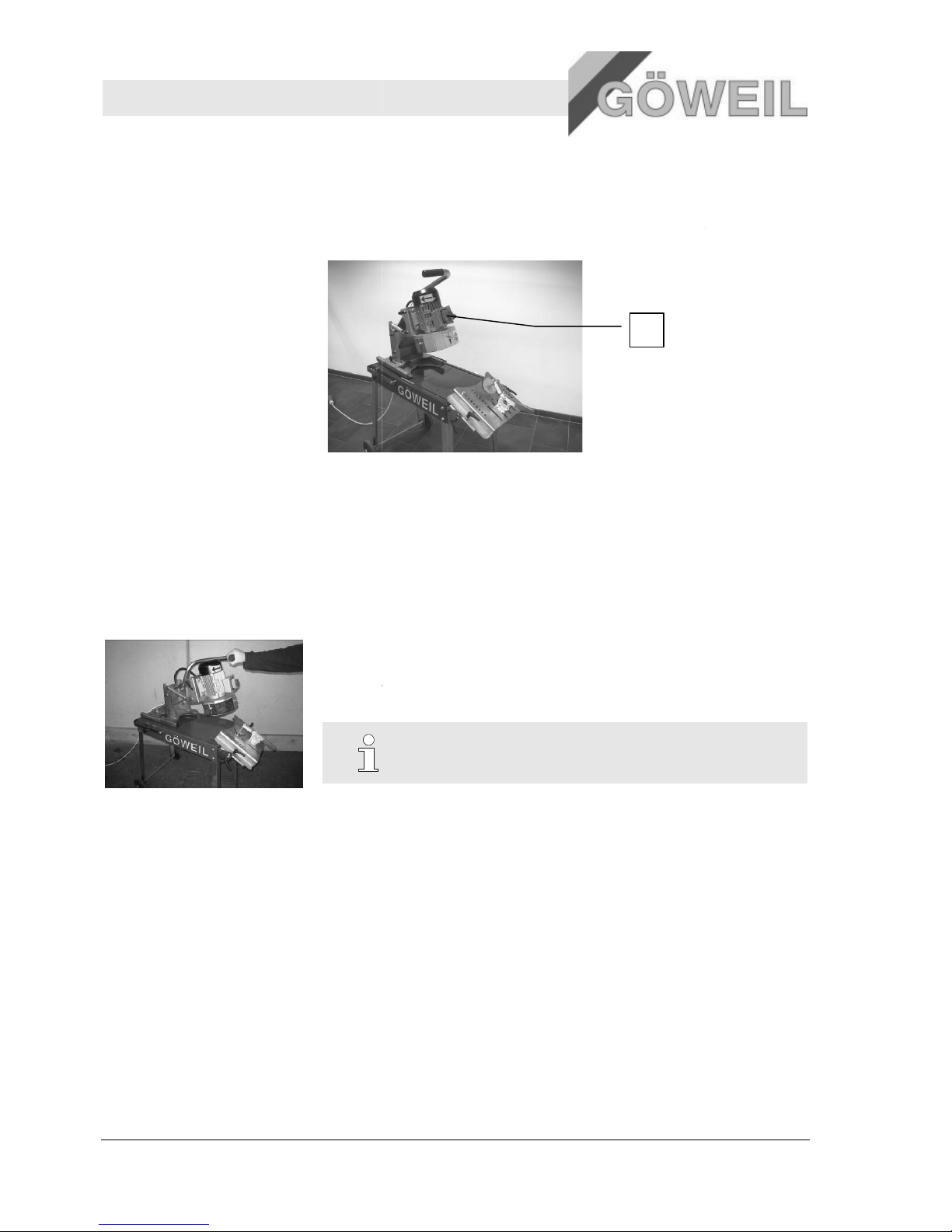
4.5 Lage der Not-Aus-Taster
4.5.1 Übersicht
Die Maschine ist mit einem
Not
sofort abgeschaltet.
1
4.6 Bedienelemente
Die Bedienung der Maschine erfolgt über
den
4.6.1 Bediengriff
Über
den Be
Absenken und Anheben der Schleifeinheit
Drehbewegung zum schleifen der Messer
4.7 Betriebsarten
Manueller Betrieb (über
-Aus-Taster ausgerüstet. Durch Drücken dieses Schalters
Not-Aus-Taster am Motor
Bediengriff.
diengriff sind folgende Funktionen möglich:
HINWEIS!
Erläuterung zum Bediengriff [→ Kapitel "6. Bedienung
Bediengriff)
1
10.03.2009
wird die Maschine
– Seite 17"].
Page 21

Messerschleifer MS 100
Transport, Verpackung
10.03.2009 17
5 Transport, Verpackung
5.1 Transportinspektion
Die Lieferung bei Erhalt unverzüglich auf Vollständigkeit und Transportschäden prüfen.
Bei äußerlich erkennbarem Transportschaden wie folgt vorgehen:
Lieferung nicht oder nur unter Vorbehalt entgegennehmen.
Schadensumfang auf den Transportunterlagen oder auf dem Lieferschein des Transporteurs vermerken.
Reklamation einleiten.
HINWEIS!
Jeden Mangel reklamieren, sobald er erkannt ist. Schadenersatzansprüche können nur
innerhalb der geltenden Reklamationsfristen geltend gemacht werden.
5.2 Verpackung
Umgang mit
Verpackungsmaterialien
Verpackungsmaterial nach den jeweils gültigen gesetzlichen Bestimmungen und örtlichen Vorschriften
entsorgen.
VORSICHT!
Umweltschäden durch falsche Entsorgung!
Verpackungsmaterialien sind wertvolle Rohstoffe und können in vielen Fällen weiter genutzt
oder sinnvoll aufbereitet und wiederverwertet werden.
Deshalb:
– Verpackungsmaterialien umweltgerecht entsorgen.
– Die örtlich geltenden Entsorgungsvorschriften beachten. Gegebenenfalls einen
Fachbetrieb mit der Entsorgung beauftragen.
6 Bedienung
6.1 Sicherheit
Persönliche
Schutzausrüstung
Folgende Schutzausrüstung bei allen Arbeiten zur Bedienung tragen:
Arbeitsschutzkleidung
Sicherheitsschuhe
Schutzbrille
Gehörschutz
Standsicherheit
WARNUNG!
Verletzungsgefahr durch nicht ausreichende Standsicherheit!
Nicht ausreichende Standsicherheit der Maschine während des Betriebes kann zu schweren
Verletzungen führen.
Deshalb:
– Maschine immer auf festen, trockenen und ebenen Untergrund abstellen und gegen
Wegrollen sichern.
Page 22

Messerschleifer MS 100
Bedienung
18 10.03.2009
Sicherheitsabstand
WARNUNG!
Verletzungsgefahr durch nicht ausreichenden Sicherheitsabstand!
Nicht ausreichender Sicherheitsabstand zu Gefahrenbereichen der Maschine kann zu
schweren Verletzungen führen.
Deshalb:
– Während des Betriebes einen ausreichenden Sicherheitsabstand zu Gefahrenbereichen
der Maschine einhalten.
Pos: 7.8 /KN2006-SM/Bedienung/003 1.1. 0 Grundlegendes @ 9\mod_ 1144402038705 _1.doc @ 8647 6
Unsachgemäße
Bedienung
WARNUNG!
Verletzungsgefahr durch unsachgemäße Bedienung!
Unsachgemäße Bedienung kann zu schweren Personen- oder Sachschäden führen.
Deshalb:
– Maschine darf nur von einer Person bedient werden.
– Alle Bedienschritte gemäß den Angaben dieser Betriebsanleitung durchführen.
– Vor Beginn der Arbeiten sicherstellen, dass alle Abdeckungen und
Sicherheitseinrichtungen installiert sind und ordnungsgemäß funktionieren.
– Niemals Sicherheitseinrichtung während des Betriebes außer Kraft setzen.
– Auf Ordnung und Sauberkeit im Arbeitsbereich achten! Lose aufeinander- oder
umherliegende Bauteile und Werkzeuge sind Unfallquellen.
6.2 Erstinbetriebnahme
Die Maschine ist durch den Hersteller nur teilweise vormontiert.
1. Die Maschine aus der Verpackung nehmen und laut beiliegender Zeichnung „Zusammenbau MS100“
montieren.
Anzugsdrehmoment für M6 => 10Nm
Anzugsdrehmoment für M8 => 25Nm
2. Topfschleifscheibe auf Beschädigungen prüfen.
3. Netzstecker anbringen.
Der entsprechende Netzstecker ist je nach Motor- und Länderausführung zu wählen.
WARNUNG!
Verletzungsgefahr durch unsachgemäße Installation der Elektrik!
Der Anschluss hat durch eine Elektrofachkraft zu erfolgen!
Es wird dringend empfohlen den jeweiligen Anschluss gegen Feuchtigkeit und Verschmutzung zu schützen.
Page 23
10.03.2009
6.3 Vorbereitungen
Pos: 7.9 /KN2006-SM/nL.......... Seitenumbruc h .......... @ 8\mod _11419983347 03_0.doc @ 7548 9
6.3.1 Inbetriebnahme
1. Maschine auf feste
n
WARNUNG!
Verletzungsgefahr durch falsches Aufstellen!
Falsches Aufstellen der Maschine kann zu schweren Verletzungen führen.
Deshalb:
–
Sicherstellen, dass erforderlicher Platzbedarf für die Bedienung der Maschine
vorhanden ist.
2. Ne
tzstecker anstecken
Den Netzstecker an einer dafür vorgesehenen Steckdose anstecken
WARNUNG
Gefahr eines Stromschlages bei falschem Hantieren mit Kabeln
3
. Topfschleifscheibe kontrollieren
WARNUNG!
Vor
jeder Inbetriebnahme ist die Topfschleifscheibe zu kontrollieren!
6.4
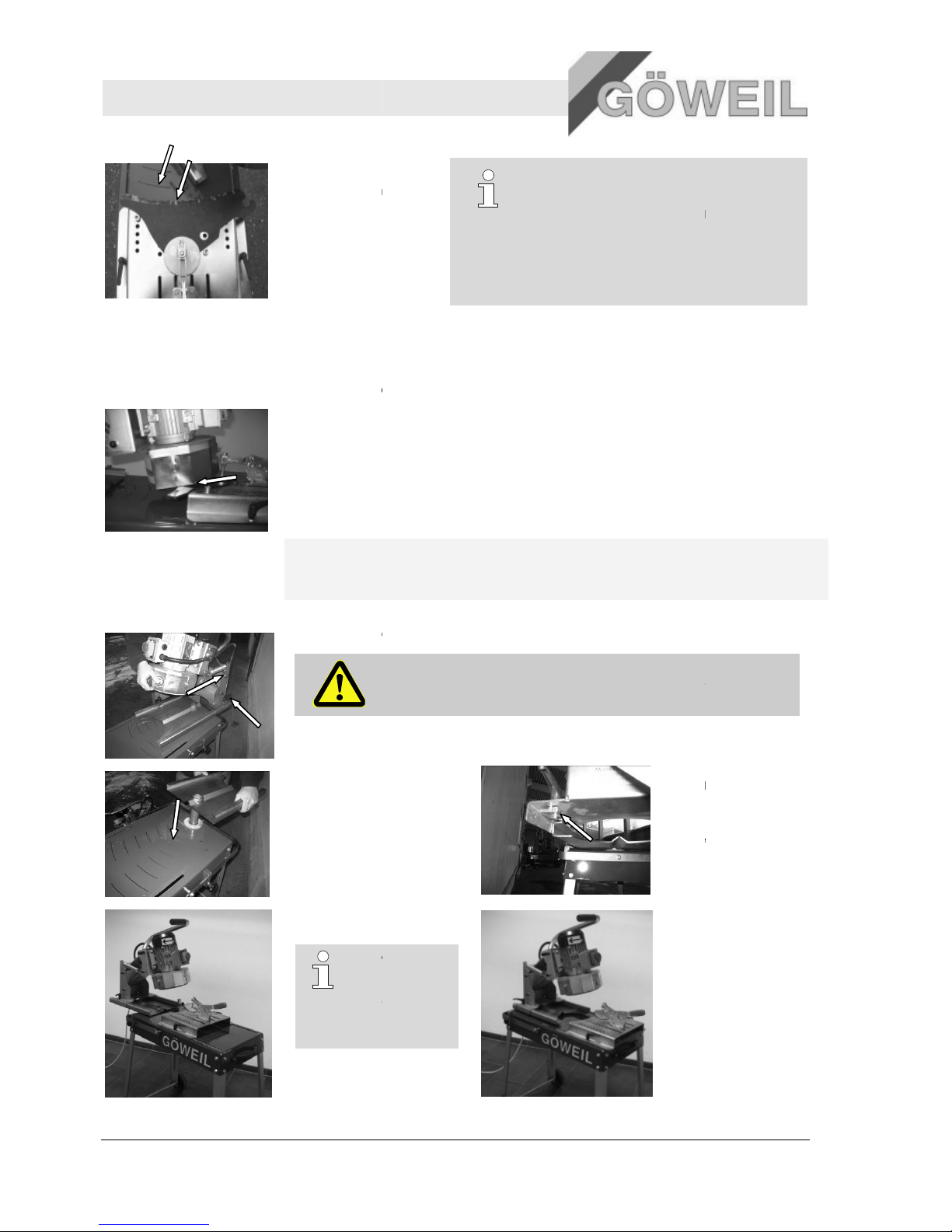
Bogenmesser positionieren
Pos: 7.18 /KN2006-SM/Bedienung/007 1.1 Still setzen im Notfall -- > Anlage und grö ssere Masc hine @ 9\mod_11 44432835796 _1.doc @ 86788
In Gefahr
ensituationen müssen Maschinenbewegungen möglichst schnell gestoppt und die Energiezufuhr
abgeschaltet werden.
Weiter muss darauf geachtet werden, dass das Bogenmesser mit de
sicher geklemmt wird und an den Anschlagschrauben satt anliegt.
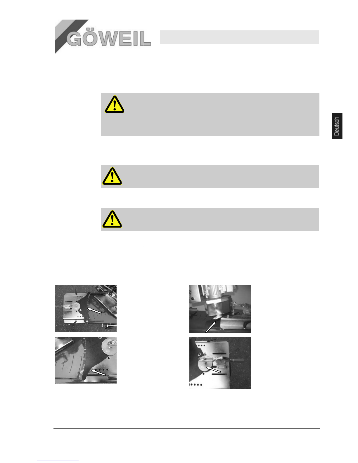
1.
Bogenmesser muss
mittig am Verstellblech
satt aufliegen. Glatte
Schneidfläche oben,
Wellenschliff unten.
3.
Anschlagschrauben so
weit wie möglich nach
außen platzieren und
fixie
ren.
Messerschleifer
und ebenen Untergrund stellen.
!
2.
4.
MS 100
Bedienung
19
!
r Spannvorrichtung
Schneidfläche muss ca.
2 cm gegenüber dem
Verstellblech vorstehen.
Spannvorrichtung so
positionieren, dass der
Messerhalter das zu
schleifende
Bogenmesser sicher
klemmt (ca. halbe
Überdeckung).
Page 24
Messerschleifer MS 100
Bedienung
20
5.
Mit Verstellblech soweit
verfahren bis der
Messerradius mit der
Radiusskala
übereinstimmt und
fixieren.
6.5 Schleifeinheit einstellen
Pos: 7.18 /KN2006-SM/Bedienung/007 1.1 Still setzen im Notfall -- > Anlage und grö ssere Masc hine @ 9\mod_11 44432835796 _1.doc @ 86788
Die Schleifeinheit ist so einzustellen, dass die Topf
nachfolgendes Foto).
.
Weiter muss darauf geachtet werden, dass das Bogenmesser mit de
sicher geklemmt wird und an den Anschlagschrauben satt anliegt.
Der Abstand zwischen dem Schutzblech der Topf
gering wie möglich sein.
Um von ganz kleinen bis zu ganz großen Radien alles Schlei
Dreheinheit
der Schleifeinheit um 180° zu drehen.
Dazu sind folgende Schritte notwendig:
1.
Klemmhebel lockern und komplette Schleifeinheit durch schieben nach hinten abnehmen.
2. Dreheinheit
der Führung nehmen und
um 180° drehen.
Dreheinheit
einsetzen.
Die
Schleifeinheit wieder von
hinten auf
die Dreheinheit
aufschieben,
und befestigen.
4. Stellung
der Dreheinheit
für kleine
Radien.
TIPP!
Bei den meisten
Messern ist die
Dreheinheit wie in
diesem Pu
dargestellt
einzustellen.
TIPP!
Es w
ird empfohlen die Kontur der Messerrücken
auf dem Verstellblech zu markieren. Damit ist die
Positionierung der nachfolgend zu schleifenden
Messer einfacher.
schleifscheibe
genau Mittig
m Waagrechtspanner
schleif
scheibe und dem Bogenmesser muss so
fen zu können ist es möglich d
ACHTUNG!
Beim Abnehmen der Schlei
feinheit darauf achten, dass diese nicht aus
den Händen rutscht – VERLETZUNGSGEFAHR!!
anheben, aus
wieder
einstellen
3.
Hier ist zu beachten,
dass auf der
Unterseite der
Schleifeinheit die
Klemmplatten richtig
eingeschoben sind!
nkt
5.
Stellung
Dreheinheit
Radien.
10.03.2009
im Eingriff ist (siehe
ie
der
für große
Page 25
10.03.2009
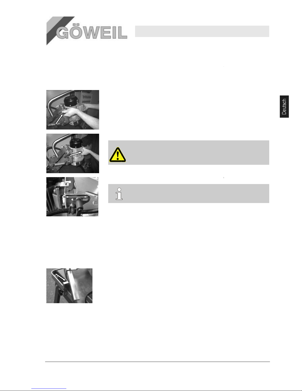
6.6
Schleifwinkel einstellen
Pos: 7.18 /KN2006-SM/Bedienung/007 1.1 Still setzen im Notfall -- > Anlage und grö ssere Masc hine @ 9\mod_11 44432835796 _1.doc @ 86788
Da b
ei den verschiedenen Messertypen der Schleifwinkel unterschiedlich ist, muss dieser
verstellbar sein.
Folgende Schritte sind notwendig:
.
Waagrechtspanner sicher geklemmt wird und an den
1.
Klemmhebel auf einer Seite lockern.
2.
Elektrom
3.
Einstellung des Schleifwinkels vornehmen und beide Klemmhebel wieder festschrauben.
6.7
Drehbegrenzer einstellen
Pos: 7.18 /KN2006-SM/Bedienung/007 1.1 Still setzen im Notfall -- > Anlage und grö ssere Masc hine @ 9\mod_11 44432835796 _1.doc @ 86788
Der Drehbegrenzer (Anschlag) soll so eingestellt werden, dass die Topf
Schleiffläche bleibt und nicht am
Die Anpassung kan
1.
Sternschraube lockern
2.
Einstellung vornehmen
3.
Sternschraube wieder festziehen.
Messerschleifer
Weiter muss darauf geachtet werden, dass das Bogenmesser mit dem
Anschlagschrauben satt anliegt.
otor mit einer Hand halten und zweiten Klemmhebel lockern.
ACHTUNG!
Beim Öffn
en des zweiten Klemmhebels den Elektrom
Vorderseite festhalten –
auf der H
VERLETZUNGSGEFAHR!!
TIPP!
Mit neuem Messer lässt sich der richtige Schleifwinkel leichter einstellen
schleif
Anfang oder am Ende des Messers über die Kante schleift.
n individuell erfolgen.
.
.
MS 100
Bedienung
21
otor nur auf der
interseite besteht
.
scheibe innerhalb der
Page 26
Messerschleifer MS 100
Bedienung
22
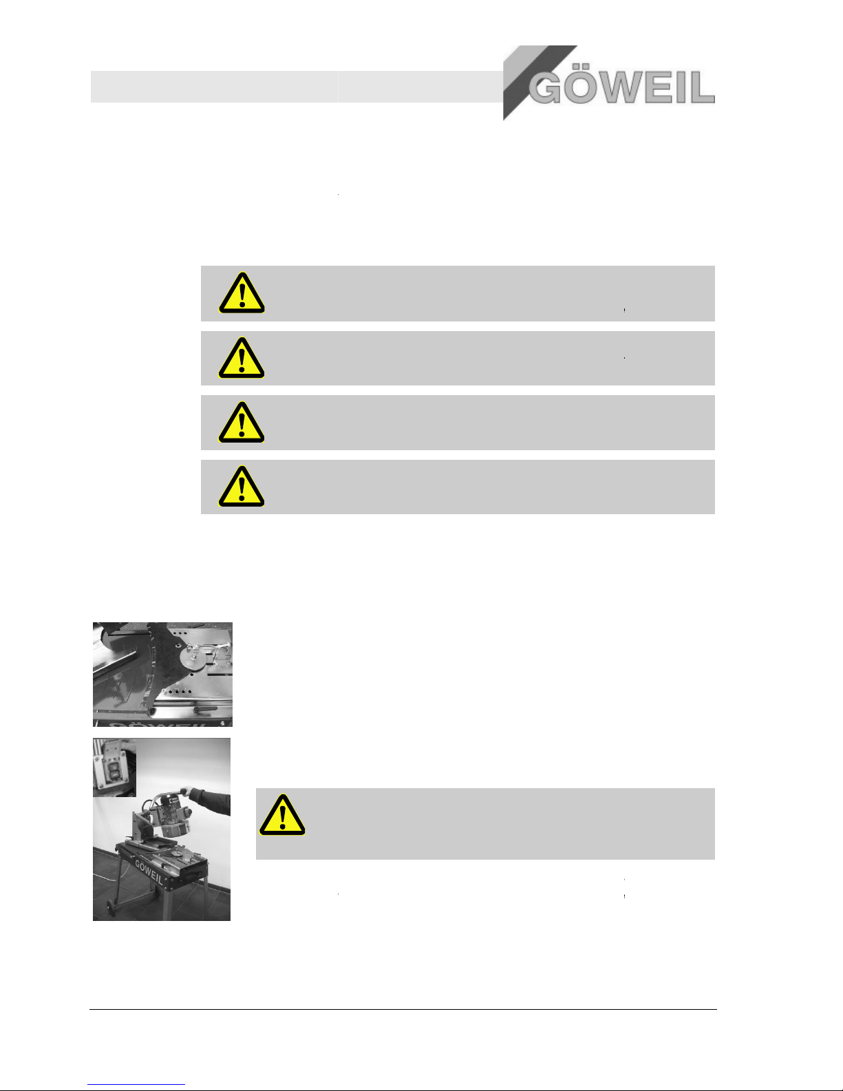
6.8 Betrieb
Persönliche
Schutzausrüstung
Folgende Schutzausrüstung bei allen Arbeiten zur Bedienung tragen:
Arbeitsschutzkleidung
Sicherheitsschuhe
Schutzbrille
Gehörschutz
Information
ACHTUNG!
Bevor Sie den Messerschleifer in Betrieb nehmen, machen Sie sich mit allen
Maschinenelementen
Anlauf-
drehmoment
ACHTUNG!
Hohes Anlaufdrehmoment des Elektrom
Be
diengriff
Messerwechsel
ACHTUNG!
Der M
esserwechsel darf nur bei komplet
erfolgen.
Schleifstelle
ACHTUNG!
Nach dem Schleifvorgang auf keinen Fall die Schleifstelle berühren da diese sehr
scharf und heiß ist! HOHES VERLETZUNGSRISIKO!
6.8.1
6.8.1 Arbeitsablauf
Zum S
chleifen der versc
.
Weiter muss darauf geachtet werden, dass das Bogenmesser mit dem Waagrechtspanner
sicher geklemmt wird und an den Anschlagschrauben satt anliegt.
1.
Bogenmesser positionieren und sicher klemmen.
positionieren“
.
Weiter muss darauf geachtet werden, dass das Bogenmesser mit dem Waagrechtspanner
sicher geklemmt wird und an den Anschlagschrauben satt anliegt.
2. Motor
mit grünem Schalter (I) auf Not
festhalten.
3.
Bogenmesser mit gleichmäßigen rechts
4.
Schleifvorgang solange wiederholen bis das Messer zur Gänze geschärft ist.
5. Elektrom
otor ausschalten, warten bis die Topfschleifscheibe stillsteht, Bogenmesser abnehmen
und nächstes zu schleifendes Messer lt. Angaben auf
positionieren“
vertraut und lesen Sie die Betriebsanleitung genau durch!
otors. Daher beim Einschalten den
festhalten.
tem Stillstand der Topfschleifscheibe
hiedenen Messer ist folgender Ablauf notwendig:
Siehe hierzu Seite 19
Pkt. 6.4
.
-Aus-Taster eins
chalten und dabei
-links Bewegungen schleifen!
ACHTUNG!
Schleifdruck darf nicht zu hoch sein! Wird zu viel Schleifdruck ausgeübt
so geht die Härte der Messer verloren (Blaufärbung der Schleif
Auf Funkenflug achten!
Seite 19
Pkt. 6.4 „Bogenmesser
wieder aufsetzen.
10.03.2009
„Bogenmesser
Bediengriff
stelle).
Page 27
10.03.2009
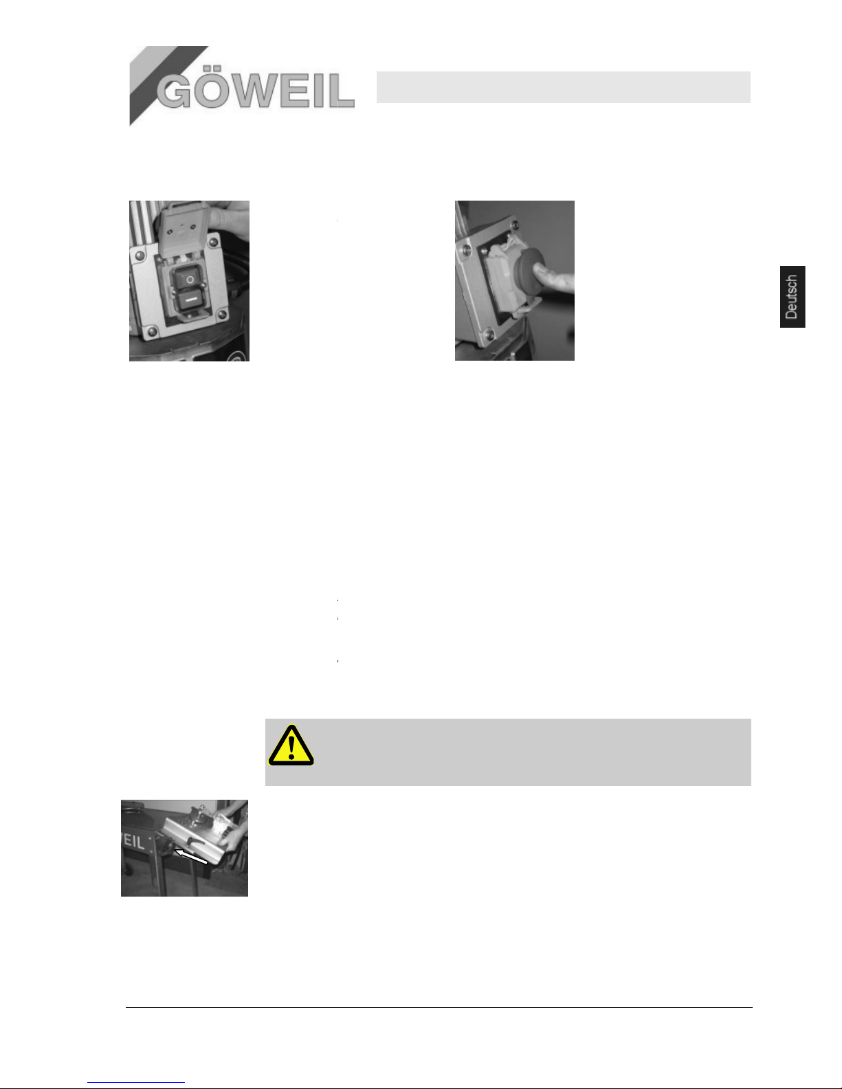
6.9
Abstellen der Maschine
1.
Maschine mit dem Aus
ausschalten (Rote Taste „0“)
6.10
Linearschleifeinheit (Zusatzausrüstung)
Die Linearschleifeinheit ermöglicht das Schleifen von geraden Messern.
Für das Schleifen von geraden Messern muss lediglich das Verste
Winkeltisch
der Linears
6.10.1
Anbau der Linearschleifeinheit
Siehe Zeichnung
„Anbau
Anzugsdrehmoment für M6 => 10Nm
Anzugsdrehmoment für M8 => 25Nm
6.10.2 Einstellung der Lin
earschleifeinheit
Die Einstellungen sind so vorzunehmen wie
„Drehbegrenzer einstellen“
.
Weiter muss darauf geachtet werden, dass das Bogenmesser mit dem Waagrechtspanner
sicher geklemmt wird und an den Anschlagschrauben satt anl
1.
Die Linearschleifeinheit entsprechend dem Schleifwinkel ausrichten. Beide Winkellaschen sind mit
je vier Ausnehmungen versehen.
Oberste Ausnehmung entspricht 0 Grad (waagrecht) des Winkeltisch. Die weiteren Abstufungen
erfolgen in 15 Grad Schritten
Schnellverschlussschrauben lösen
Messerschleifer
-Schalter
2.
Die verriegelbare
Abdeckung des Not
Schalters zudrücken bi
einrastet.
3.
Den Netzstecker ziehen
llblech vom Schleiftisch auf den
chleifeinheit montiert werden.
Linearschleifeinheit“.
.
.
auf Seite 19 Pkt. 6.
3 „Vorbereitungen“ bis Seite 21
beschrieben.
WICHTIG!
Es muss darauf geachtet werden, dass beim Schleifen von geraden Messern die zu
sc
hleifende Fläche waagrecht stehen muss. D.h., auch die Topfschleifscheibe
muss waagrecht ausgerichtet sein!
iegt.
.
– Winkel einstellen –
Schnellverschlussschrauben festziehen.
MS 100
Bedienung
23
-Aus
s sie
Pkt. 6.7
Page 28
Messerschleifer MS 100
Bedienung
24
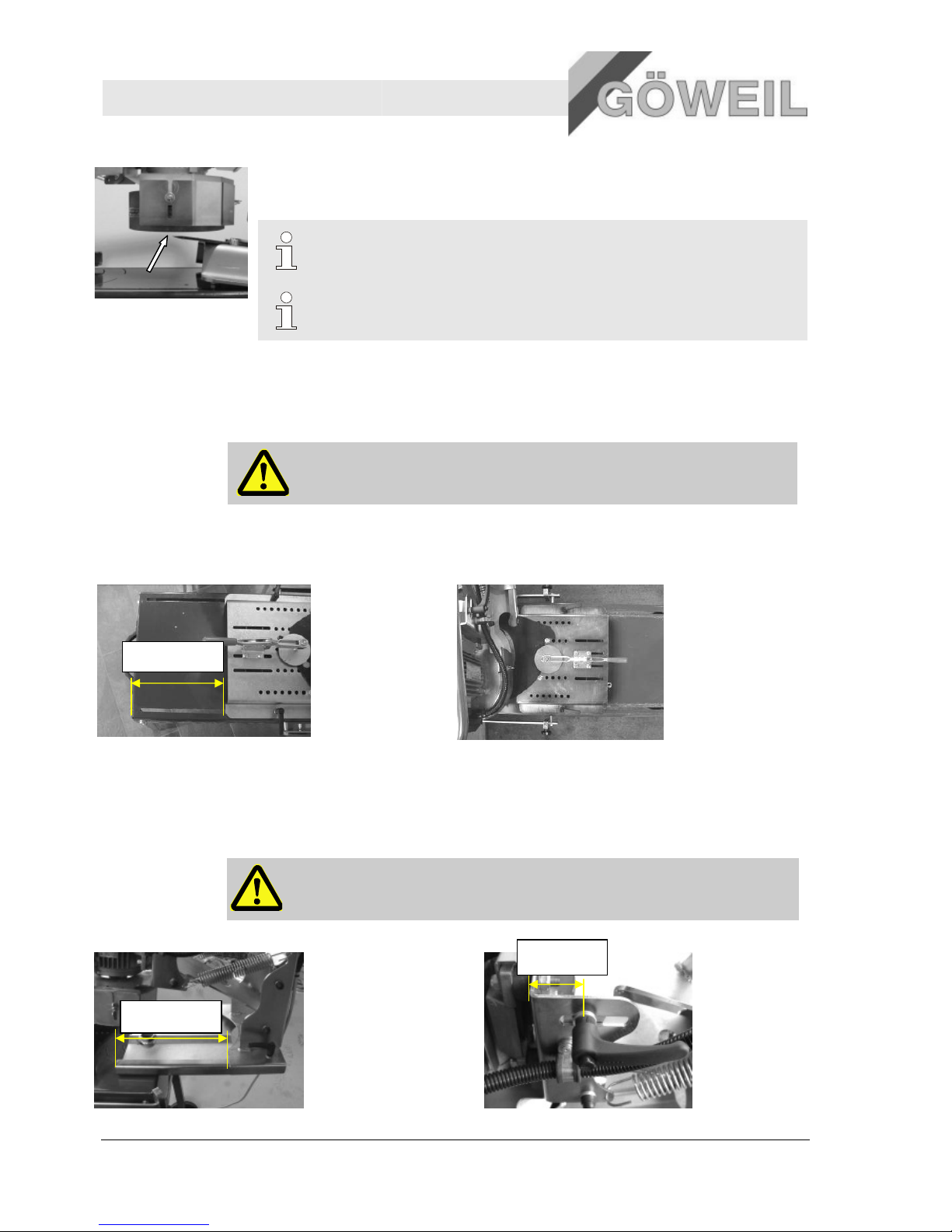
. Weiter muss darauf geachtet werden, dass das Bogenmesser mit dem Waagrechtspanner
sicher geklemmt wird und an den Anschlagschrauben satt anliegt.
2. Die Topfschleifscheibe
„Schleifwinkel einstellen“)
3. Der Arbeitsablauf ist der gleiche wie
HINWEIS!
Wenn die Linearschleifeinheit nicht b
TIPP!
Mit neuem Messer lässt sich der richtige Schleifwinkel leichter einstellen.
6.11 Messer für Rundballenpresse Krone VP 1500 und VP 1800 positionieren
Nachfolgend aufgeführt sind spezielle Einstellvorgaben für Krone
1800!
WICHTIG!
Die nachfolgenden Werte sind nur Richtwerte da sie je nach Messerverschleiß leicht
unterschiedlich sein können!
6.11.1 Einstellung des Verstellbleches
Das angegebene Maß ist nur als Richtwert zu verstehen!
6.11.2 Schleifeinheit einstellen
6.11.2.1 Halteblech – Abstand, Schleifwinkel einstellen
WICHTIG!
Die Dreheinheit der Schleifeinheit muss um 180
Pkt. 6.5“Schleifeinheit einstellen“
D
ca275mm
ca270mm
Weiter muss darauf geachtet werden, dass das Bogenmesser mit dem Waagrechtspanner
sicher geklemmt wird und an den Anschlagschrauben satt anliegt.
schleifscheibe und die Schleiffläche waagrecht (0 Grad) ausrichten (Seite 21
einstellen“)
Der Arbeitsablauf ist der gleiche wie auf Seite 22 Pkt. 6.8.1 „Arbeitsablauf“ beschrieben.
HINWEIS!
Wenn die Linearschleifeinheit nicht benötigt wird kann sie weggeklappt werden.
Mit neuem Messer lässt sich der richtige Schleifwinkel leichter einstellen.
Messer für Rundballenpresse Krone VP 1500 und VP 1800 positionieren
rt sind spezielle Einstellvorgaben für Krone – Messer der Rundballenpresse VP 1500,
Die nachfolgenden Werte sind nur Richtwerte da sie je nach Messerverschleiß leicht
unterschiedlich sein können!
Einstellung des Verstellbleches, Messerposition am Verstellblech
Das angegebene Maß ist nur als Richtwert zu verstehen!
Richtige Position des Messers!
, Schleifwinkel einstellen
nheit der Schleifeinheit muss um 180° gedreht werden! Siehe Seite 20
Pkt. 6.5“Schleifeinheit einstellen“
Die angegebenen Maße sind nur als Richtwert zu verstehen!
ca40mm
10.03.2009
Weiter muss darauf geachtet werden, dass das Bogenmesser mit dem Waagrechtspanner
Seite 21 Pkt. 6.6
beschrieben.
enötigt wird kann sie weggeklappt werden.
Mit neuem Messer lässt sich der richtige Schleifwinkel leichter einstellen.
Messer für Rundballenpresse Krone VP 1500 und VP 1800 positionieren
Messer der Rundballenpresse VP 1500,
Die nachfolgenden Werte sind nur Richtwerte da sie je nach Messerverschleiß leicht
° gedreht werden! Siehe Seite 20
Page 29

22
Messerschleifer MS 100
Störungen
25 10.03.2009
7 Störungen
Im folgenden Kapitel sind mögliche Ursachen für Störungen und die Arbeiten zur ihrer Beseitigung beschrieben.
Bei vermehrt auftretenden Störungen sind die Wartungsintervalle entsprechend der tatsächlichen Belastung zu
verkürzen.
Bei Störungen, die durch die nachfolgenden Hinweise nicht zu beheben sind, einen Vertragshändler in ihrer
Nähe oder den Hersteller kontaktieren.
7.1 Sicherheit
Personal
Die hier beschriebenen Arbeiten zur Störungsbeseitigung können, soweit nicht anders
gekennzeichnet, durch den Bediener ausgeführt werden.
Einige Arbeiten dürfen nur von speziell ausgebildetem Fachpersonal oder ausschließlich durch den
Hersteller ausgeführt werden, darauf wird bei der Beschreibung der einzelnen Störungen gesondert
hingewiesen.
Arbeiten an der elektrischen Anlage dürfen grundsätzlich nur von Elektrofachkräften ausgeführt
werden.
Persönliche
Schutzausrüstung
Folgende Schutzausrüstung bei allen Störungsarbeiten tragen:
Arbeitsschutzkleidung
Sicherheitsschuhe
Sichern gegen
Wiedereinschalten
GEFAHR!
Lebensgefahr durch unbefugtes Wiedereinschalten!
Bei Arbeiten zur Störungsbeseitigung besteht die Gefahr, dass die Energieversorgung
unbefugt eingeschaltet wird. Dadurch besteht Lebensgefahr für die Personen im
Gefahrenbereich.
Deshalb:
– Vor Beginn der Arbeiten alle Energieversorgungen abschalten und gegen
Wiedereinschalten sichern.
– Netzstecker ziehen
Unsachgemäße
Störungsbeseitigung
WARNUNG!
Verletzungsgefahr durch unsachgemäße Störungsbeseitigung!
Unsachgemäße Störungsbeseitigung kann zu schweren Personen- oder Sachschäden
führen.
Deshalb:
– Vor Beginn der Arbeiten für ausreichende Montagefreiheit sorgen.
– Auf Ordnung und Sauberkeit am Montageplatz achten! Lose aufeinander- oder
umherliegende Bauteile und Werkzeuge sind Unfallquellen.
– Wenn Bauteile entfernt wurden, auf richtige Montage achten, alle
Befestigungselemente wieder einbauen und Schraubenanzugsdrehmomente
einhalten.
– Alle Abdeckungen und Sicherheitseinrichtungen vorschriftsmäßig montieren und
auf Funktion prüfen.
Page 30
Messerschleifer MS 100
Störungen
26
Verhalten bei
Störungen
Grundsätzlich gilt:
1.
Bei Störungen, die eine unmittelbare Gefahr für Personen oder Sachwerte darstellen, sofort die Not
Funktion ausführen.
2. Störungsurs
ache ermitteln.
3.
Falls die Störungsbehebung Arbeiten im Gefahrenbereich erfordert, ausschalten und gegen
Wiedereinschalten sichern.
4.
Verantwortlichen am Einsatzort über Störung sofort informieren.
5. Je n
ach Art der Störung diese von autorisiertem Fach
HINWEIS!
Die im Folgenden aufgeführte Störungstabelle gibt Aufschluss darüber, wer zur Behebung
der Störung berechtigt ist.
7.2 Störungstabelle
7.2.1 Allgemeine Störungen
Störung Mögliche Ursache
Elektromotor ohne
Funktion
Stromversorgung fehlt
Defekte Sicherung
Beschädigtes Verbin
dungs
kabel
Elektromotor schaltet
sich nach kurzer Zeit
aus
Thermoschutz gefallen /
aktiv
Topfschleifscheibe
vibriert
Unwucht, Teile
ausgebrochen
7.3 Störungsbehebung
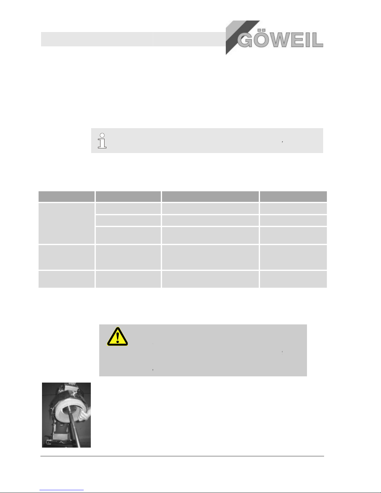
7.3.1
Topfschleifscheibe wechseln
WICHTIG!
Die Topfschleifscheibe muss entsprechend den Herstellerangaben
verwendet werden!
Die Topfschleifscheibe darf nur von unterwiesenem Bedienpe
getauscht werden!
Die Topfschleifscheibe darf max. bis zum Ende des Verstellbereiches des
einstellbaren Schutzbleches verwendet werden!
.
Weiter muss darauf geachtet werden, dass das Bogenmesser mit dem Waagrechtspanner sicher
geklemmt wird und
an den Anschlagschrauben satt anliegt.
1.
Die Topfschleifscheibe auf der Unterseite mit entsprechendem Werkzeug losschrauben und mit einer
Hand festhalten.
per
sonal beseitigen lassen oder selbst beheben.
Abhilfe
Beheben durch
Versorgungskabel der Maschine anstecken Bediener
Sicherung im Schaltschrank ersetzen
Elektrofachkraft
- Verbindungskabel austauschen
Elektrofachkraft
Stecker kontrollieren
Ist der Elektromotor richtig nach Schaltplan
angeschlossen
Elektrofachkraft
ersetzen Bediener
10.03.2009
-Aus-
rsonal
Page 31
10.03.2009
.
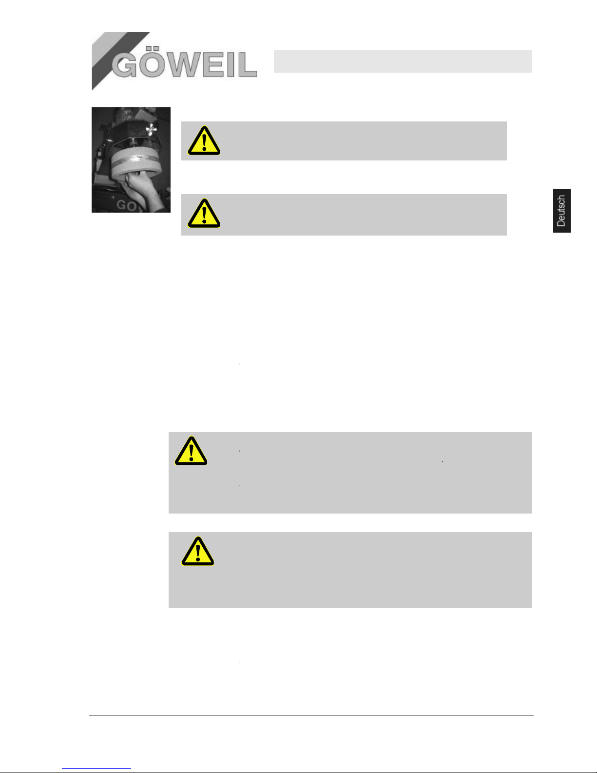
Weiter muss darauf geachtet werden, dass das Bogenmesser mit dem Waagrechtspanner sicher
gekle
mmt wird und an den Anschlagschrauben satt anliegt.
2.
Die Topfschleifscheibe mit der
WICHTIG!
3.
Die neue Topfschleifscheibe m
Anzugs
drehmoment für M8 => 25Nm
GEFAHR!
8 Instandhaltung
Pos: 9.3 /KN2006-SM/Wartung/002 1 Sicherh eit_Titel @ 9\mo d_114443483 1619_1.doc @ 8681 0
8.1 Sicherheit
Pos: 9.4 /KN2006-SM/Wartung/003 1.1.0 Personal --> Standard --
> ggf. anpassen @ 9
Personal
Die hier beschriebenen Wartu
ausgeführt werden.
Einige Wartungsarbeiten dürfen nur von speziell ausgebildetem Fachpersonal oder
den Hersteller ausgeführt werden, darauf wird bei der Besch
gesondert hingewiesen.
Arbeiten an der elektrischen Anlage dürfen grundsätzlich nur von Elektrofachkräften ausgeführt werden.
Persönliche
Schutzausrüstung
Folgende Schutzausrüstun
Arbeitsschutzkleidung
Sicherheitsschuhe
Sichern gegen
Wiedereinschalten
GEFAHR!
Lebensgefahr durch unbefugtes Wieder
Bei Wartungsarbeiten besteht die Gefahr, dass die Energieversorgung unbe
eingeschaltet wird. Dadurch besteht Lebensgefahr für die Personen im Gefahrenbereich.
Deshalb:
–
Federspannung
VORSICHT!
Verletzungsgefah
Unter Federspannung stehende Hebel können zu Verletzungen führen.
Deshalb:
–
Bei Arbeiten an
–
Ausreichenden Sicherheitsabstand einhalten.
Umweltschutz
Folgende
Hinweise zum Umweltschutz bei den Wartungsarbeiten beachten:
An allen Schmierstellen, die von Hand mit Schmierstoff versorgt werden, das austretende, verbrauchte oder
überschüssige Fett entfernen und nach den gültigen örtlichen Bestimmungen entsorgen.
Messerschleifer
Instand
Spannscheibe
von der Motorachse abziehen.
Die gebrauchte Topfschleifscheibe entsprechend als Gebraucht
markieren und entsorgen!
it der Spannscheibe
auf die Motorachse schieben und festschrauben.
.
Die neue Topfschleifscheibe darf keinen Stößen ausgesetzt werden!
GEFAHR des Berstens bei Betrieb!
\mod_1144434832402_1.doc @ 86817
ngsarbeiten können, soweit nicht anders gekennzeichnet, durch den Bediener
reibung der einzelnen Wartungsarbeiten
g bei allen Wartungsarbeiten tragen:
einschalten!
Vor Beginn der Arbeiten alle Energieversorgun
gen abschalten und gegen
Wiedereinschalten sichern.
r durch Zurückschnellen des Hebels!
unter Federspannung stehende Hebel
vorsichtig vorgehen.
MS 100
haltung
27
ausschließlich durch
fugt
Page 32

Messerschleifer MS 100
Instandhaltung
28
8.2 Wartungsplan
In den nachstehenden Abschnitten sind die Wartungsarbeiten beschrieben, die für einen optimalen und
störungsfreien Betrieb erforderlich sind.
Sofern bei regelmäßigen
Wartungsintervalle entsprechend den tatsächlichen
Bei Fragen zu Wartungsarbeiten und
Intervall
(Bh –
Betriebsstunden)
Wartungsarbeit
Allgemein
Vor jeder
Benutzung
Fremdkörper und Verschmutzungen entfernen
Beweglichkeit der Bauteile
Zustand der Topfschleifscheibe
Abnützung der Topfschleifscheibe
jährlich Führungslager der Dreheinheit
schmieren
8.3 Wartungsarbeiten
8.3.1 Gelenke schmieren
Zusätzlich benötigte Schutzausrüstung:
Schutzhandschuhe
Schmierstoffe
WARNUNG!
Feuergefahr, Vergiftungsgefahr und Gesundheitsschäden durch Schmierstoffe!
Schmierstoffe k
Kontakt mit Öl und Fett kann zur Gesundheits
Deshalb:
–
Kein offenes Feuer bei Arbeiten an der Maschine.
–
Nicht rauchen.
– Öl-
und Fettdämpfe nicht einatmen.
–
Hautkontakt mit Öl und Fett
–
Öl und Fett umgehend von der Haut entfernen.
An der Schleifmaschine ist nur das Führungslager de
zu schmieren.
Kontrollen eine erhöhte Abnutzung zu erkennen
ist, die erforderlichen
Verschleißerscheinungen verkürzen.
-intervallen den Hersteller oder einen Vertragshändler
kontaktiere
Auszuführen durch
Bediener
Bediener
Bediener
Bediener
Bediener
önnen sich beim Kontakt mit Zündquellen entzünden.
schädigung führen.
vermeiden.
r Dreheinheit mit
handelsüblichen Mehrzweckf
10.03.2009
n.
ett
Page 33
Messerschleifer MS 100
Demontage
10.03.2009 29
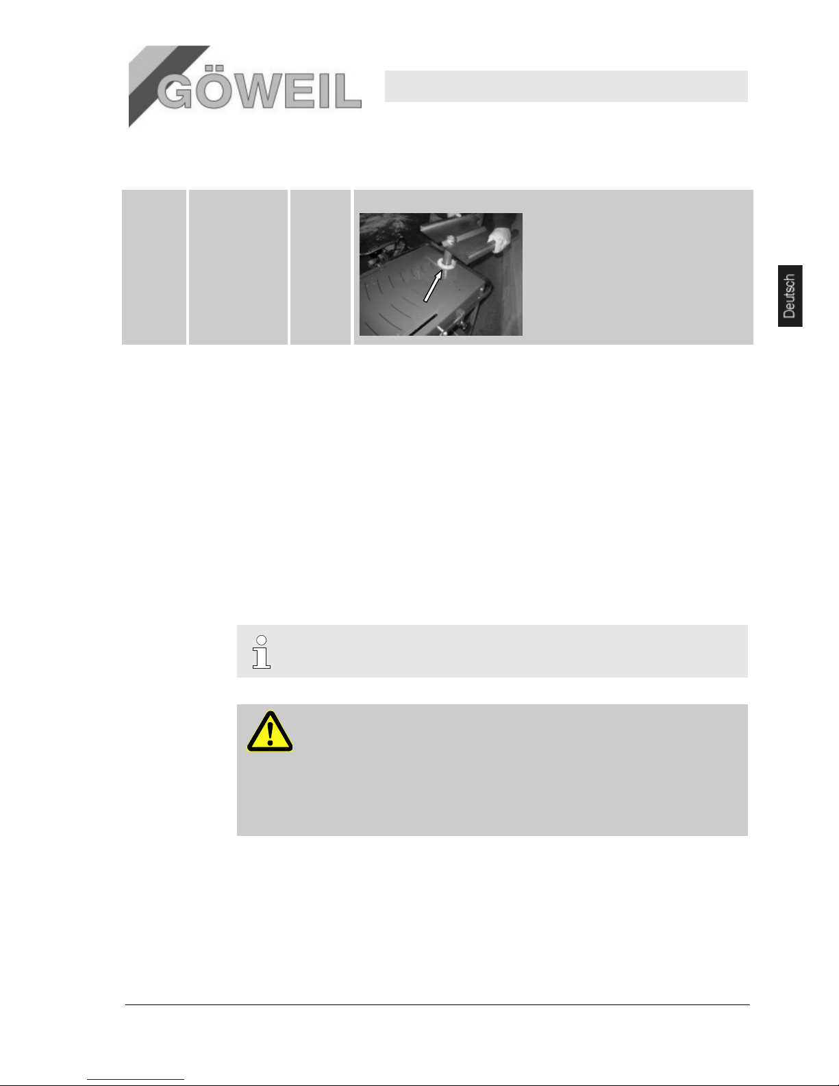
8.4 Schmierplan
jährlich Führungslager der
Dreheinheit
1 Lager Führungslager vorher reinigen!
8.5 Maßnahmen nach erfolgter Wartung
Pos: 9.33 /KN2006-SM/Wartung/009 1.1.0 M assnahmen n ach erfolgter Wartung --> Sta ndard @ 9\mo d_114443898 1309_1.doc @ 8 6935
Nach Beendigung der Wartungsarbeiten vor dem Einschalten die folgenden Schritte durchführen:
1. Alle zuvor gelösten Schraubenverbindungen auf festen Sitz überprüfen.
2. Überprüfen, ob alle zuvor entfernten Schutzvorrichtungen und Abdeckungen wieder ordnungsgemäß
eingebaut sind.
3. Sicherstellen, dass alle verwendeten Werkzeuge, Materialien und sonstige Ausrüstungen aus dem
Arbeitsbereich entfernt wurden.
4. Arbeitsbereich säubern und eventuell ausgetretene Stoffe wie z. B. Flüssigkeiten,
Verarbeitungsmaterial oder Ähnliches entfernen.
5. Sicherstellen, dass alle Sicherheitseinrichtungen der Maschine einwandfrei funktionieren.
9 Demontage
Pos: 10.3 /KN2006-SM/Demontage/001 1. 0 Nachdem das G ebrauchsend e erreicht ist. ..(Anlage) @ 9\m od_11445018 94460_1.doc @ 87460
Nachdem das Gebrauchsende erreicht ist, muss die Maschine demontiert und einer umweltgerechten
Entsorgung zugeführt werden.
Pos: 10.4 /KN2006-SM/nL---------- Abschnittsende ---------- @ 8\mod_1141997892953_0.doc @ 75471
HINWEIS!
Die Demontage erfolgt ausschließlich durch fachkundige Personen.
WARNUNG!
Gefahr durch fehlerhafte Demontage!
Demontage erfordert geschultes Fachpersonal mit ausreichender Erfahrung. Fehler bei der
Demontage können zu lebensgefährlichen Situationen führen oder erhebliche Sachschäden
mit sich bringen.
Deshalb:
– Demontage ausschließlich durch Mitarbeiter des Herstellers ausführen lassen.
– Eigenmächtige Demontage unterlassen.
9.1 Entsorgung
Sofern keine Rücknahme- oder Entsorgungsvereinbarung getroffen wurde, zerlegte Bestandteile der
Wiederverwertung zuführen:
Metalle verschrotten.
Kunststoffelemente zum Recycling geben.
Übrige Komponenten nach Materialbeschaffenheit sortiert entsorgen.
Page 34

Messerschleifer MS 100
Ersatzteile/Anhang
30 10.03.2009
VORSICHT!
Umweltschäden bei falscher Entsorgung!
Elektroschrott, Elektronikkomponenten, Schmier- und andere Hilfsstoffe unterliegen der
Sondermüllbehandlung und dürfen nur von zugelassenen Fachbetrieben entsorgt werden!
Die örtliche Kommunalbehörde oder spezielle Entsorgungs-Fachbetriebe geben Auskunft zur umweltgerechten
Entsorgung.
Pos: 11.1 /KN2006-Projekte/Rüfenacht/Ers atzteilliste/1 Ersa tzteile - Titel @ 47\mod_ 1190042012578 _1.doc @ 623734
10 Ersatzteile
Pos: 11.2 /KN2006-Projekte/Uviterno/UV - Tro cknungss ysteme/Ersatzteillist e/1.0 Nur Orig inal-Ersatzteile verwenden-U V-Trockner @ 49\mod_11932 37144634_1.d oc @ 762140
WARNUNG!
Verletzungsgefahr durch falsche Ersatzteile!
Falsche oder fehlerhafte Ersatzteile können zu Beschädigungen, Fehlfunktionen oder
Totalausfall führen sowie die Sicherheit beeinträchtigen.
Deshalb:
– Nur Originalersatzteile des Herstellers verwenden.
Ersatzteile über Vertragshändler oder direkt beim Hersteller beschaffen! Die Ersatzteilliste befindet sich im
Anhang. Bei Verwendung nicht freigegebener Ersatzteile verfallen jegliche Garantie- und Serviceansprüche!
Pos: 11.3 /KN2006-SM/nL--------- - Abschnittsende ------ ---- @ 8\mod_11 41997892953_0 .doc @ 75471
10.1 Ersatzteilbestellung
Pos: 11.5 /KN2006-Projekte/Uviterno/UV - Tro cknungss ysteme/Ersatzteillist e/1.1 Ersatzt eilbestellung - T ext-UV-Troc kner @ 49\mod _1193237232 019_1.doc @ 762228
Bei Ersatzteilbestellungen bitte unbedingt angeben:
Bezeichnung
Typ
Baujahr
Artikel-Nummer gemäß Ersatzteilliste im Anhang
Menge
gewünschte Versandart (Post, Fracht, See, Luft, Express)
Versandadresse
Ersatzteilbestellungen ohne diese Angaben können nicht berücksichtigt werden. Bei fehlender Angabe über die
Versandart erfolgt Versand nach Ermessen des Herstellers/Lieferanten.
11 Anhang
SM/nL.......... Seitenumbruch .......... @ 8\ mod_11419983 34703_0.doc @ 75489
Pos: 12.3 /KN2006-Projekte/NSD Lift AG/A nhang/1.1 Inhal t @ 54\mod_ 1196948759959 _1.doc @ 8758 50
11.1 Fremdunterlagen
Komponente Benennung Typ Hersteller
Elektromotor (400V) Drehstrom-Käfigläufermotor Y3-80B2 KEDU KJD18 Moll-Motor
Elektromotor (230V) Einphasen-Wechselstrommotor Y3E-80B2 KEDU KJD18 Moll-Motor
11.2 Ersatzteillisten / Montagezeichnungen / Schaltpläne
Siehe Anhang
Page 35

Operating instructions
Knife sharpener
MS 100
Page 36

EC Declaration of Conformity
in accordance with EC Directive 98/37/EC
GÖWEIL MASCHINENBAU GMBH
(Name of seller)
A-4202 Kirchschlag, Eben 128
(full address of the company or its authorized representative established in the Community as well as the company
and address of the manufacturer)
declares on its own responsibility that the product
Knife sharpener MS 100
(make, type)
to which this declaration refers to corresponds to the relevant fundamental safety and
health requirements of EC Directive 98/37/EC,
(if applicable)
as well as the requirements of the other relevant EC Directives
98/37/EC Machinery Directive, Annex 1
2006/42/EC Machinery Directive, implemented in Austria by Federal Law
Gazette I No. 8/2008 as amended from time to time
2006/95/EC Low Voltage Directive
(Title and/or number as well as issue date of the other EC Directives)
corresponds to.
(if applicable)
The following standard(s) and/or technical specification(s) were used for the appropriate
application of the safety and health requirements described in the EC Directives:
EN 294; EN 349; EN 547-1; EN 614-1; EN 563; EN 894; EN 953;
EN ISO 13849 – 1; EN 999; EN 1037; EN ISO 12100; EN 13850;
EN ISO 14121; EN 60204-1
(Title and/or number as well as issue date of the standard(s) and/or of the technical specification(s))
Kirchschlag, 12.03.2007 Herbert Göweil, Managing Director
(Place and date of issue) (Name, function, and signature of the authorized person)
Page 37

22
Knife sharpener MS 100
Contents
10.03.2009 1
1 General information ..................................................................................... 3
1.1 About this manual .............................................................................. 3
1.2 Explanation of symbols ...................................................................... 3
1.3 Limitation of liability ............................................................................ 4
1.4 Copyright ........................................................................................... 4
1.5 Spare parts ........................................................................................ 4
1.6 Warranty terms .................................................................................. 4
1.7 Customer service ............................................................................... 4
2 Safety ............................................................................................................ 5
2.1 Intended use ...................................................................................... 5
2.2 Responsibilities of the operator .......................................................... 5
2.3 Personnel requirements ..................................................................... 6
2.4 Personal protective equipment ........................................................... 7
2.5 Specific hazards ................................................................................ 8
2.6 Safety fixtures .................................................................................... 9
2.7 Safeguard against restart ................................................................. 10
2.8 Behavior in the event of danger or accidents ................................... 10
2.9 Environmental protection ................................................................. 10
2.10 Signage ........................................................................................... 11
2.11 Warning signs .................................................................................. 11
2.12 Modifications .................................................................................... 11
3 Technical Data ............................................................................................ 12
3.1 General specifications ...................................................................... 12
3.2 Connected loads .............................................................................. 12
3.3 Operating conditions ........................................................................ 13
3.4 Emissions ........................................................................................ 13
3.5 Working materials ............................................................................ 13
3.6 Nameplate ....................................................................................... 13
4 Design and function ................................................................................... 14
4.1 Overview ......................................................................................... 14
4.2 Brief description ............................................................................... 14
4.3 Connections ..................................................................................... 15
4.4 Work and hazard areas .................................................................... 15
4.5 Position of the emergency stop buttons ........................................... 16
4.6 Controls ........................................................................................... 16
4.7 Operating modes ............................................................................. 16
5 Transport, packaging ................................................................................. 17
5.1 Transport inspection ........................................................................ 17
5.2 Packaging ........................................................................................ 17
6 Operation .................................................................................................... 17
6.1 Safety .............................................................................................. 17
6.2 Initial operation ................................................................................ 18
6.3 Preparations .................................................................................... 19
6.4 Positioning curved knives................................................................. 19
6.5 Adjusting the grinding unit ................................................................ 20
6.6 Adjusting the grinding angle ............................................................. 21
6.7 Adjusting the rotation limiter ............................................................. 21
Page 38

Knife sharpener MS 100
Contents
2 10.03.2009
6.8 Operation ........................................................................................ 21
6.9 Switching the machine off................................................................ 23
6.10 Linear grinding unit (additional equipment) ...................................... 23
6.11 Positioning knives for Krone VP 1500 and VP 1800 round bale
presses ........................................................................................... 24
7 Faults .......................................................................................................... 25
7.1 Safety .............................................................................................. 25
7.2 Table of faults ................................................................................. 26
7.3 Troubleshooting .............................................................................. 26
8 Maintenance ............................................................................................... 27
8.1 Safety .............................................................................................. 27
8.2 Maintenance schedule .................................................................... 28
8.3 Maintenance steps .......................................................................... 28
8.4 Lubrication chart .............................................................................. 29
8.5 Steps after maintenance is complete ............................................... 29
9 Disassembly .............................................................................................. 30
9.1 Disposal .......................................................................................... 30
10 Spare parts ................................................................................................. 31
10.1 Ordering spare parts ....................................................................... 31
11 Appendix .................................................................................................... 31
11.1 Third-party documents .................................................................... 31
11.2 Replacement parts lists / Assembly drawings / Circuit diagrams ...... 31
Page 39
22
Knife sharpener MS 100
General information
10.03.2009 3
1 General information
Pos: 1.2 /KN2006-SM/Allgemeines/110 1.1 Informatione n zur Anleitung (A nlage) @ 9\mo d_114440275 0137_1.doc @ 8 6521
1.1 About this manual
These instructions allow you to handle the machine in a safe and efficient manner.
These instructions are an integral part of the machine and must be kept close to the machine where they are
accessible to the personnel at all times. The personnel must have carefully read and understood these
instructions before beginning work. Compliance with all specified safety information and operating instructions
are essential for safe operation.
All local accident prevention and general safety regulations applicable to the machine's area of application must
be observed as well.
The illustrations used throughout these instructions are intended to provide a general understanding and may
vary from the actual model of the machine.
In addition to these instructions, the instructions of the installed components included in the appendix apply as
well.
1.2 Explanation of symbols
Safety information
The safety information provided in these instructions are marked by symbols. The safety information
are introduced by keywords indicating the extent of the danger.
Strictly adhere to all safety instructions and proceed with care to prevent accidents as well as
personal injury and property damage.
DANGER!
… warns of an immediately dangerous situation which may cause death or serious injury
unless avoided.
WARNING!
… warns of a possibly dangerous situation which may cause death or serious injury unless
avoided.
CAUTION!
… warns of a possibly dangerous situation which may cause slight or minor injuries unless
avoided.
CAUTION!
… warns of a possibly dangerous situation which may cause property damage unless
avoided.
Tips and
recommendations
NOTICE!
… highlights tips and recommendations as well as information that may also be useful in
connection with the efficient and trouble-free operation of the machine.
Specific safety
information
The following symbols are included in the safety information to point out specific hazards:
… marks hazards caused by electric current. Failure to observe the safety information may
lead to serious or fatal injuries.
Page 40

Knife sharpener MS 100
General information
4 10.03.2009
1.3 Limitation of liability
All specifications and information provided in these instructions have been compiled in consideration of all
applicable standards and regulations, the state of the art and our long years of expertise and experience.
The manufacturer is not liable for any damages caused by:
Failure to observe these instructions
Improper use
Use of untrained personnel
Unauthorized retrofitting
Technical modifications
Use of unapproved spare parts
The actual scope of supply may vary from the explanations and illustrations herein for special models and
custom orders or due to the latest technical modifications.
The duties agreed upon in the delivery contract, the manufacturer's Terms and Conditions and terms of delivery
as well as the statutory regulations applicable at the time of conclusion of contract shall apply.
We reserve the right to make technical modifications in order to improve and further develop the performance
characteristics of our machines.
1.4 Copyright
These instructions are protected by copyright and intended for in-house purposes only.
Unless for in-house purposes, making these instructions available to third parties, duplications in any shape and
form - even in excerpts - or using and/or disclosing their content is prohibited without the written approval of the
manufacturer.
Non-compliance is subject to compensation for damages. Further claims remain reserved.
Pos: 1.14 /KN2006-SM/nL--------- - Abschnittsende ------ ---- @ 8\mod_11 41997892953_0 .doc @ 75471
1.5 Spare parts
WARNING!
Safety risk due to incorrect spare parts!
Wrong or defective spare parts may impact safety and lead to damage, malfunctions or
complete failure.
Therefore:
– Use only original spare parts made by the manufacturer.
Purchase spare parts from authorized dealers or directly from the manufacturer. A replacement parts list is
included in the appendix.
1.6 Warranty terms
Pos: 1.19 /KN2006-SM/Allgemeines/161 1. 1.0 Garantieb estimmungen i n den AGB des H erstellers @ 9\mod_1144054 766031_1.doc @ 84763
The maximum warranty period granted by the manufacturer is 1 year.
Pos: 1.14 /KN2006-SM/nL--------- - Abschnittsende ------ ---- @ 8\mod_11 41997892953_0 .doc @ 75471
1.7 Customer service
Contact our customer service for any technical information you may require. The members of our staff are also
interested in any new information or experiences resulting from the use of our products and which may help
improve the performance of our products.
Page 41

22
Knife sharpener MS 100
Safety
10.03.2009 5
2 Safety
Pos: 2.3 /KN2006-SM/Sicherheit/001 1.0 Ein führung @ 8\ mod_1142427 208593_1.doc @ 77470
This section provides an overview of all important safety aspects required to keep the personnel safe at all times
and ensure the safe and trouble-free operation of the machine.
Failure to follow the operating instructions and safety information provided in this manual may lead to
considerable danger.
2.1 Intended use
The machine is designed and constructed only for the intended use described herein.
The knife sharpener is intended only for sharpening concave, curved knifes - as well as straight knifes when
combined with the optional "linear grinding unit" - which are used in agricultural presses and trailers with
loading facility.
Any other use is NOT considered appropriate. The manufacturer shall NOT be responsible for any damages
or accidents resulting from such inappropriate use!
The risk lies solely with the operator. Intended use also includes observing all operating, maintenance and
repair instructions specified by the manufacturer.
WARNING!
Danger due to incorrect use!
Any use exceeding or deviating from the intended use of the machine may lead to
dangerous situations.
Therefore:
– Use the machine only as intended.
– Strictly adhere to all specifications provided in these operating instructions.
Avoid the following types of use in particular:
– all grinding operations outside of the range of intended use
No claims for any damages arising from inappropriate use will be accepted.
2.2 Responsibilities of the operator
The machine is used in the commercial and the private sector. As a consequence, all commercial operators of
the machine are required to observe their statutory obligations with regard to occupational health and safety.
Apart from the safety information provided in these instructions, all safety, accident prevention and
environmental regulations applicable to the machine's area of application must be observed as well. The
following applies in particular:
The operator must become familiar with all applicable occupational health and safety regulations and
conduct a risk assessment to determine the hazards resulting from the special work conditions present at
the machine's area of application. The results of such an assessment must be implemented into the
operating instructions of the machine.
The operator must verify throughout the entire time the machine is in use whether the operating instructions
he or she created comply with the latest revision of the corresponding regulations and revise them if
necessary.
The operator must clearly define and assign the responsibilities for installing, operating, maintaining and
cleaning the machine.
The operator must ensure that all employees handling the machine have read and understood these
instructions.
The operator must train the personnel and inform them about all hazards involved on a regular basis.
The operator must provide the personnel with all required protective equipment.
Page 42

Knife sharpener MS 100
Safety
6 10.03.2009
The operator is also responsible for keeping the machine in the proper technical condition at all times. To this
end:
The operator must ensure that the maintenance intervals described in these instructions are observed.
The operator must check regularly if all safety fixtures are present and function properly.
Before transporting the machine, the operator must verify that the machine can be transported safely.
2.3 Personnel requirements
2.3.1 Qualifications
WARNING!
Risk of injury due to insufficient qualification!
Improper handling may cause significant personal injury and property damage.
Therefore:
– Have all activities performed by qualified personnel only.
The operating instructions specify the following qualifications as required for the different areas of operation.
Instructed persons
have been instructed by the manufacturer about the tasks assigned to them and informed about the hazards
that may arise from improper behavior.
Qualified personnel
are capable of performing the tasks assigned to them and independently detecting and avoiding any
possible danger thanks to their professional training, expertise and experience as well as their familiarity
with all applicable regulations.
Trained electrician
are capable of performing work on the electrical system and independently detecting and avoiding any
possible danger thanks to their professional training, expertise and experience as well as their familiarity
with all applicable regulations and standards.
Trained electricians have received specific training for the site at which they work and are familiar with all
applicable standards and regulations.
Personnel may only be composed of persons who can be expected to perform the work assigned to them in
a reliable manner. Persons under the age of 16 or whose ability to respond is impaired, for example, by
drugs, alcohol or medication are not permitted to handle the machine.
When selecting personnel, follow all specific regulations on age and occupation applicable at the site of
installation.
2.3.2 Unauthorized personnel
WARNING! Danger to unauthorized personnel!
Unauthorized persons who do not meet the requirements described herein are not familiar
with the hazards present in the work area.
Therefore:
– Keep all unauthorized personnel away from the work area.
– If in doubt, address the corresponding persons and ask them to leave the work area.
– Suspend all work for as long as there are unauthorized persons in the work area.
Page 43
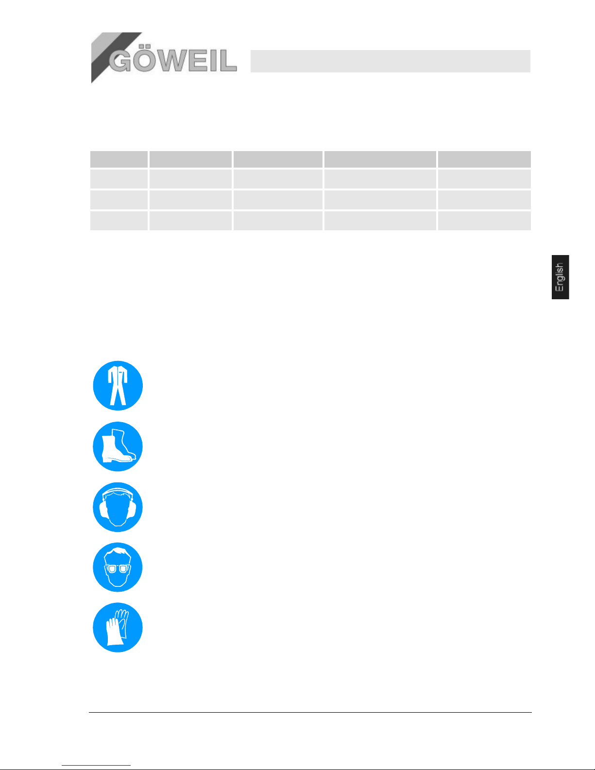
22
Knife sharpener MS 100
Safety
10.03.2009 7
2.3.3 Training
The personnel must be given regular training by the operator. All instructions must be recorded to provide proof
that training was given.
Date Name Type of instruction Instruction given by Signature
2.4 Personal protective equipment
Personal protective equipment must be worn for all work activities to prevent health hazards.
Wear the protective equipment necessary for the specific task and until all work is complete.
Follow all notices regarding personnel protective equipment that are attached in the work area.
Pos: 2.22 /KN2006-SM/Sicherheit/006 Pers önliche Schutza usstattung/ 006 1.1.0_1 Gru ndsätzlich zu trag en_Titel @ 8\ mod_1143360 998458_1.doc @ 80989
Always wear:
Wear the following during all work activities:
Protective clothing
is tight fitting work clothing of low tensile strength, with tight sleeves and without any protruding parts. It is
primarily used to provide protection against entanglement in moving parts of machinery.
Do not wear any rings, chains or other kind of jewelry.
Safety shoes
to provide protection against heavy falling parts and slipping on slick surfaces.
Hearing protection
to protect against hearing damage.
Safety goggles
to protect the eyes from flying parts, splashes of liquid and grinding splatter.
Protective gloves
to protect the hands from friction, abrasions, piercing, cuts or deeper wounds as well as contact with hot
surfaces.
Page 44

Knife sharpener MS 100
Safety
8 10.03.2009
Pos: 2.27 /KN2006-SM/Sicherheit/006 Pers önliche Schutza usstattung/ 006 1.1.0_2 Bei b esonderen Ar beiten zu tragen _Titel @ 8\mo d_114336112 2656_1.doc @ 8 0999
2.5 Specific hazards
The following section specifies residual risks that have been determined based on a risk assessment.
Follow the safety information listed herein as well as the warnings contained in the following chapters of
these instructions to lower the risks of health hazards and avoid dangerous situations.
Moving parts
WARNING!
Risk of injury caused by moving parts!
Serious injury may be caused by rotating parts and/or parts moved in linear direction.
Therefore:
– Never reach into or perform work on any moving parts while the machine is in operation.
– Do not open any covers during operation.
– Take coasting times into consideration:
Before changing the knifes your want to sharpen, make sure none of the parts is still
moving.
– Wear tight fitting clothes when inside the hazard area of the machine.
Noise
WARNING!
Hearing damage caused by noise!
The noise level created in the work zone may cause severe hearing damage.
Therefore:
– Always wear hearing protection during work.
– Do not stay inside the hazard area longer than necessary.
Hot surfaces
CAUTION!
Risk of burns on hot surfaces!
Contact with hot components may cause burns.
Freshly sharpened knifes are very hot on the ground surface!
Therefore:
– Always wear protective clothing and gloves when working close to hot components.
– Before commencing work, make sure that all components have cooled down to ambient
temperature.
Spring tension
CAUTION!
Risk of injury caused by spring breakage!
Springs under tension may cause injury.
Therefore:
– Use caution when working on levers under spring tension.
– Keep at a safe distance.
Sharp edges
and pointed
corners
CAUTION!
Risk of injury on edges and corners!
The sharp edges and pointed corners on the machine may cause skin abrasions and cuts.
Therefore:
– Use caution when working close to sharp edges and pointed corners.
– Wear protective gloves when in doubt.
Page 45
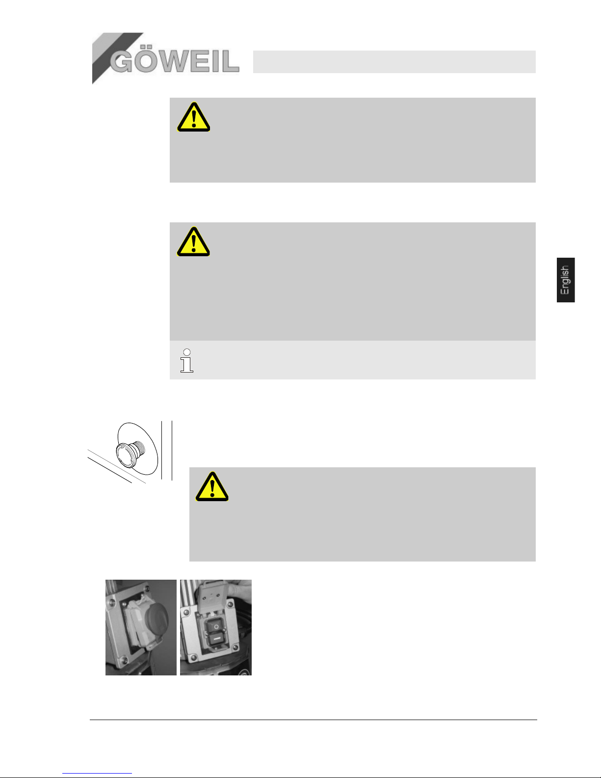
22
Knife sharpener MS 100
Safety
10.03.2009 9
Dirt and
objects lying
about
CAUTION!
Tripping hazard due to dirt and objects lying about!
Contamination and objects lying about are slipping and tripping hazards and may cause
serious injury.
Therefore:
– Keep the work area clean at all times.
– Remove objects that are no longer needed.
2.6 Safety fixtures
WARNING!
Risk of fatal injuries due to faulty safety fixtures!
Safety is only assured when all safety fixtures function properly.
Therefore:
– Before commencing work, check if all safety fixtures have been correctly installed and
function properly.
– Never disable any safety fixtures.
– Never bypass or alter any safety components.
– Make sure that safety fixtures such as emergency stop buttons, emergency trip wires,
etc. are accessible at all times.
NOTICE!
For information on the location of the safety fixtures, see chapter "Design and function."
The following safety fixtures have been installed:
Emergency stop button
Pressing the emergency stop button triggers an emergency stop.
Once pressed, the
emergency stop button must be released by sliding before the machine can be
switched back on.
WARNING!
Risk of fatal injury caused by uncontrolled restart!
Uncontrolled restart may cause serious personal injury or death!
Therefore:
– Before turning the machine back on, make sure that the cause that triggered the
emergency stop has been removed and all safety fixtures are installed and
function properly.
– Do not release the emergency stop button until there is no more danger.
Safety switch (Emergency Stop)
The safety switch is located at the front on the electric motor.
Page 46

Knife sharpener MS 100
Safety
10 10.03.2009
2.7 Safeguard against restart
DANGER!
Risk of fatal injury caused by unauthorized restart!
Work in the hazard area of the machine always involves the risk of the power supply being
switched on without authority. This may cause fatal injuries to any person inside the hazard
area of the machine.
Therefore:
– Follow the information on safeguarding against restart provided in the chapters of these
instructions.
– Follow the procedure applied to safeguard the machine against unauthorized restart as
described below.
Power is supplied to the machine only via a mains connection and a (country-specific) plug.
Equipped either with 400V or 230V electric motor
Safeguard against restart:
1. Press the emergency stop button until it locks into place.
2. do not continue to work until this condition has been set
2.8 Behavior in the event of danger or accidents
Preventive
measures
Always be prepared for accidents or fire!
Keep first aid equipment (first aid kit, blankets, etc.) and fire extinguishers readily available.
Familiarize your personnel with all accident signaling, first aid and rescue equipment.
Keep access roads clear for rescue vehicles.
Measures in the
event of
accidents
Immediately trigger an emergency stop.
Initiate first aid measures.
Rescue any persons from inside the hazard area.
Notify the person in charge on site.
Notify the emergency medical service.
Clear all access roads for rescue vehicles.
2.9 Environmental protection
CAUTION!
Environmental hazard caused by improper handling of substances that are harmful to
the environment!
If handled improperly, substances that are harmful to the environment may cause significant
environmental damage, especially when disposed of improperly.
Therefore:
– Always follow the instructions given below.
– Take immediate action when harmful substances have leaked into the environment by
accident. If in doubt, report the damage to the responsible local authorities.
The following environmentally hazardous substances are used:
Lubricants
Lubricants such as greases and oils contain toxic substances. They must not enter the environment. They
must be disposed of by a professional waste disposal company.
Page 47
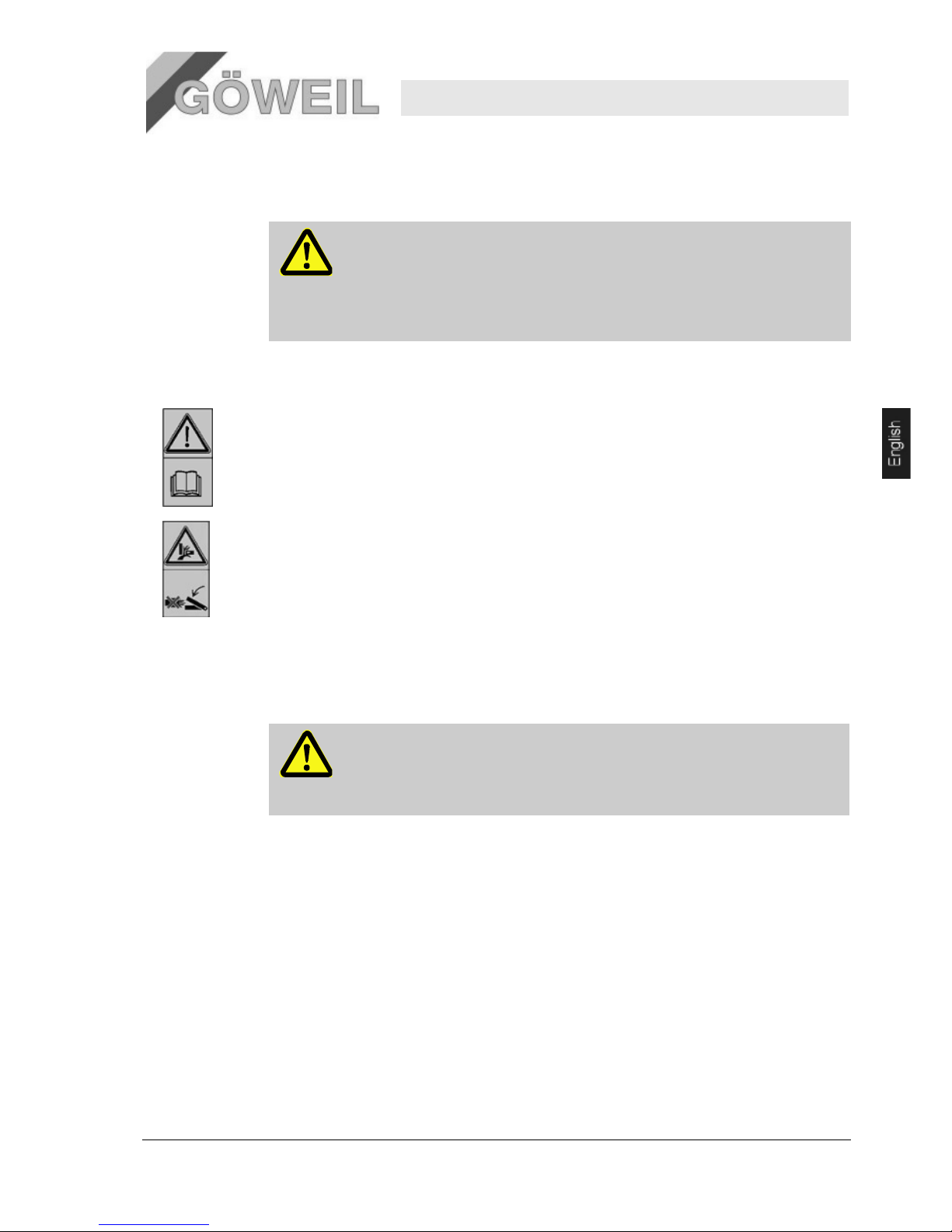
22
Knife sharpener MS 100
Safety
10.03.2009 11
2.10 Signage
The following symbols and information signs are located in the work area. They refer to the immediate area in
which they are attached.
WARNING!
Risk of injury due to illegible symbols!
Over time, stickers and signs may become soiled or rendered illegible for other reasons.
Therefore:
– Keep all safety, warning and operating information easily legible at all times.
– Replace any damaged signs or stickers immediately.
2.11 Warning signs
Follow the operating instructions
Do not use the marked object until you have read the operating instructions.
Crushing hazards
Warning of crushing hazards on a piece of work equipment (e.g. a machine) or structural equipment (e.g.
covers, enclosures, protectors, fences).
Pay particular attention when working in the marked workplaces.
Never reach into the crushing danger area as long as parts in this area may still be moving.
2.12 Modifications
WARNING!
Risk of injury caused by unauthorized modifications!
Modifications to the machine in the sense of extensions and reconstructions and, in
particular, modifications that may affect the safety of the machine are prohibited without
consulting the manufacturer and without the written approval of the manufacturer.
Page 48

22
Knife sharpener MS 100
Technical Data
12 10.03.2009
3 Technical Data
3.1 General specifications
Specification Value Unit
Weight 69 kg
Length 930 mm
Width 675 mm
Height 1455 mm
Model Without linear grinding unit
Specification Value Unit
Weight 73 kg
Length 1105 mm
Width 675 mm
Height 1455 mm
Model With linear grinding unit
NOTICE!
For technical specifications (dimensions, weights, ratings, etc.), please refer to the
included layout plans (delivery drawings) and datasheets [→ Appendix].
3.2 Connected loads
Pos: 3.6 /KN2006-Projekte/NSD Lift AG/Te chnische Date n/002 1.1.0 Anschl usswerte --> NSD Comfort @ 45\mod_11 87710014840 _1.doc @ 566 242
Electrical
Specification (400V model) Value Unit
Voltage 400/230 V
Rating 1,1 kW
Frequency 50 Hz
Speed 2835 rpm
Protection class IP55
Electrical
Specification (230V model) Value Unit
Voltage 230 V
Rating 1,1 kW
Frequency 50 Hz
Speed 2835 rpm
Protection class IP55
Page 49
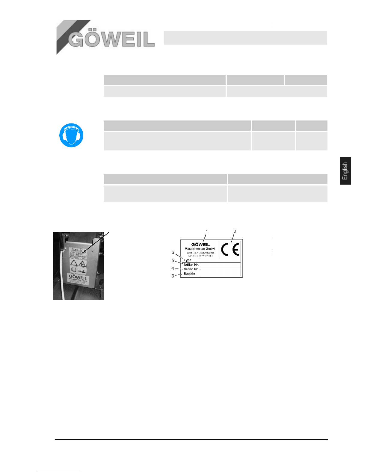
10.03.2009
3.3 Operating conditions
Pos: 3.9 /KN2006-Projekte/NSD Lift AG/Tech nische Daten/003 1.1.0 Betriebsbe dingungen --> LSD Comfort @ 4 5\mod_11877 10247081_1.doc @ 566257
Duration
Specification
Maximum continuous operating time
3.4 Emissions
Pos: 3.12 /KN2006-Projekte/NSD Lift AG/Techni sche Daten/00 5 1.1.0 Emissio nen --> LSD Comf ort @ 45\mod _1187711003739 _1.doc @ 566 337
Specification
Noise emissions (no
-
3.5 Working materials
Working material
Lubricating grease
3.6 Nameplate
The nameplate is located
on the rear of the
grinding unit.
Knife sharpener
Technical Data
Value
designed for continuous operation
load operation / grinding) 75-
80
Type
lithium-
saponified multipurpose grease NLGI
class 2
The nameplate contains the
following information:
1
Manufacturer
2
CE mark
3
Year of manufacture
4
Serial number
5
Item number
6
Type
MS 100
13
Unit
Value Unit
/ 102-105 dB(A)
Page 50
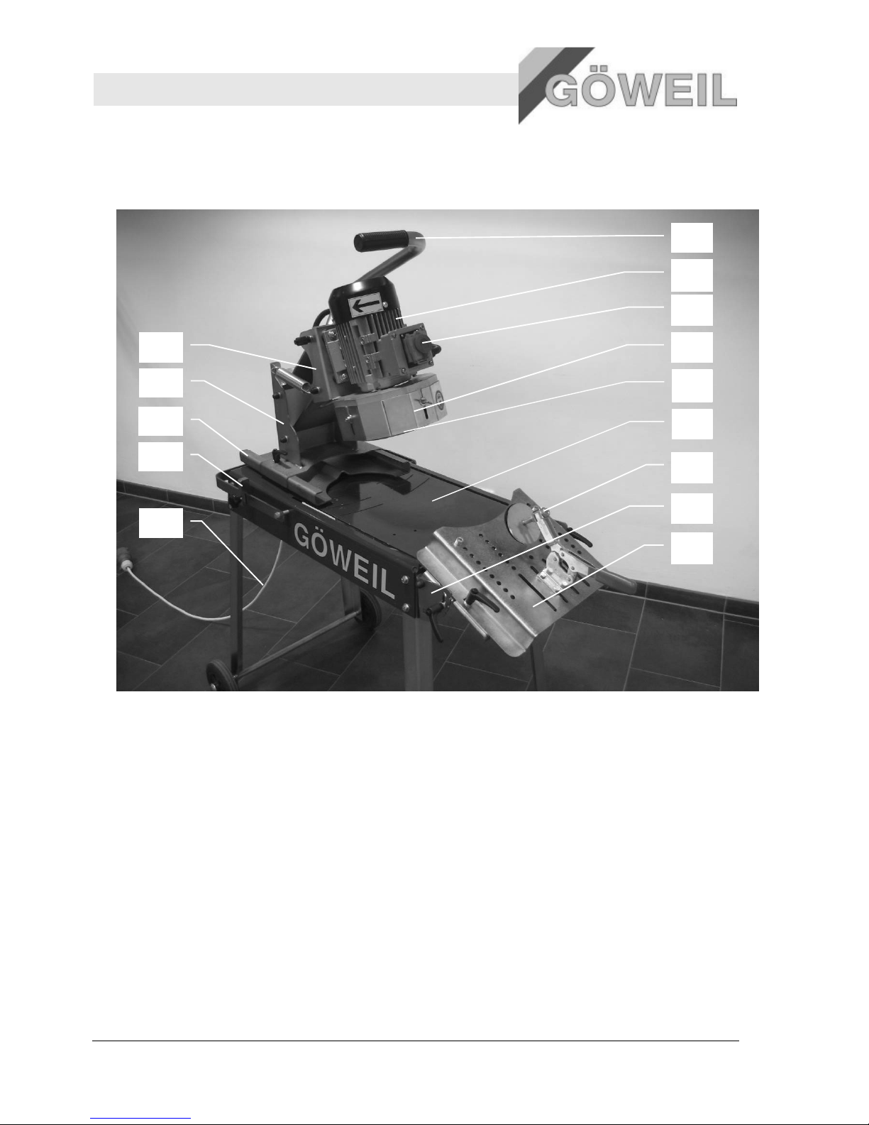
Knife sharpener MS 100
Design and function
14 10.03.2009
4 Design and function
Pos: 4.3 /KN2006-SM/Aufbau und Funktio n/002 1.1 Üb ersicht_Titel @ 9\mod_11440 46023684_1.doc @ 84432
4.1 Overview
Pos: 4.4 /KN2006-Projekte/NSD Lift AG/A ufbau und Fun ktion/1.1 Übersic ht --> NSD C omfort @ 45\mo d_11876975851 02_1.doc @ 5 66022
1 Operating handle
2 Electric motor
3 ON/OFF switch with EMERGENCY STOP
4 Protection plate (adjustable)
5 Grinding disc
6 Grinding table
7 Clamping device
8 Linear grinding unit (additional equipment)
9 Adjusting plate
10 Motor support
11 Support unit
12 Rotary unit
13 Rotation limiter
14 Connection cable
4.2 Brief description
The knife sharpener is intended only for sharpening concave, curved knives - as well as straight
knives when combined with the optional "linear grinding unit" - which are used in agricultural
presses and trailers with loading facility.
Place the knife onto the adjusting plate and fix it in place using the clamping device. Now, you
must adjust the grinding unit on the rotary plate such that the knife can be sharpened at the
corresponding radius. When all these adjustments have been made, you can sharpen the knife.
1
2
3
4
5
6
7
8
9
10
11
12
13
14
Page 51
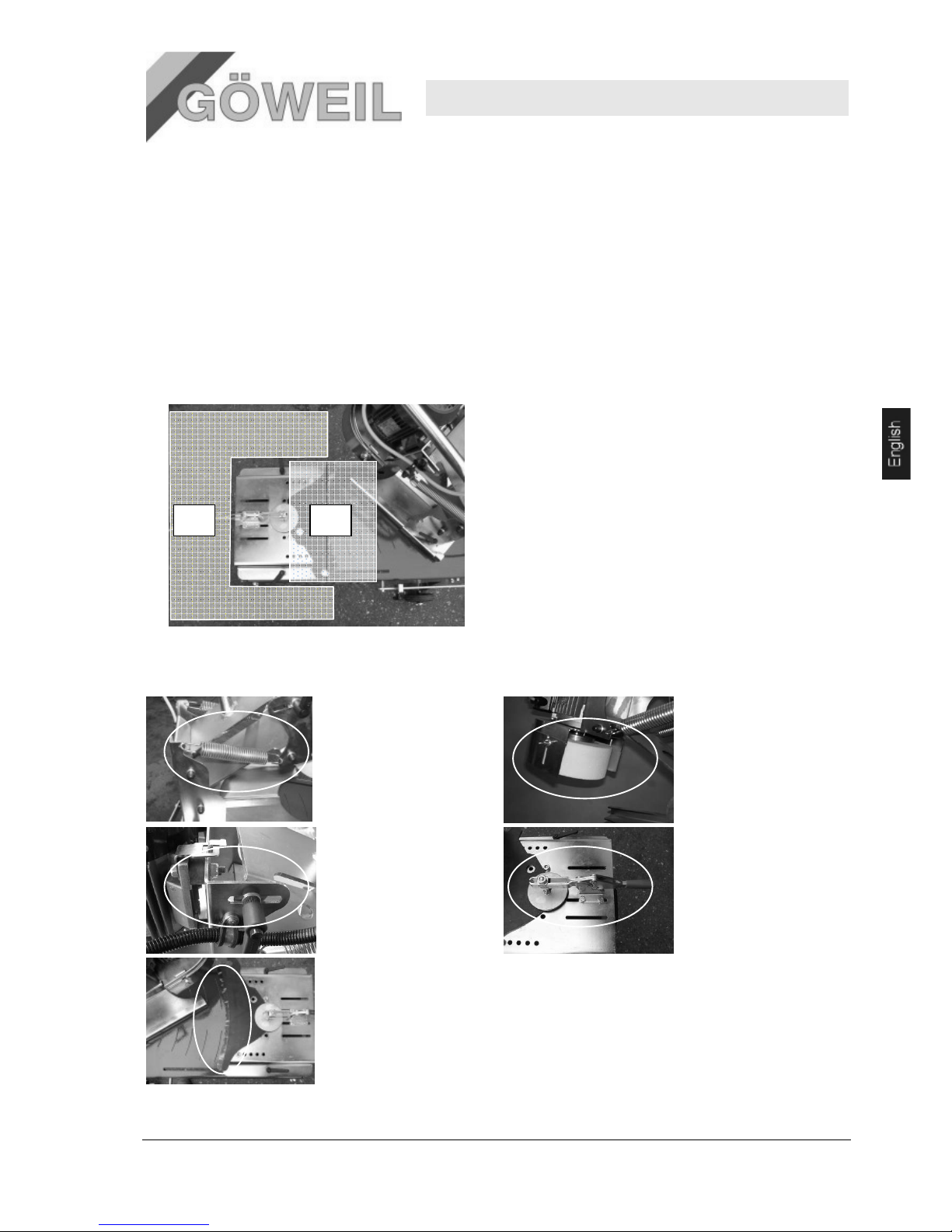
Knife sharpener MS 100
Design and function
10.03.2009 15
4.3 Connections
4.3.1 Electrical connections
The knife sharpener is shipped without a power plug. The country-specific electrical connection must,
therefore, be established by a trained electrician. Make sure to always observe the motor rotation
direction! Make sure to connect the plug following the included circuit diagram!
4.4 Work and hazard areas
4.4.1 Work areas
1. Area in front of the machine
2. Grinding area
4.4.2 Hazard areas
1. Lever mechanism
for lifting and
lowering the motor
fixture
2. Cup grinding
wheel
3. Mechanism used to
adjust the grinding
angle
4. Clamping
device for
clamping the
knives
5. Grinding surface
Page 52
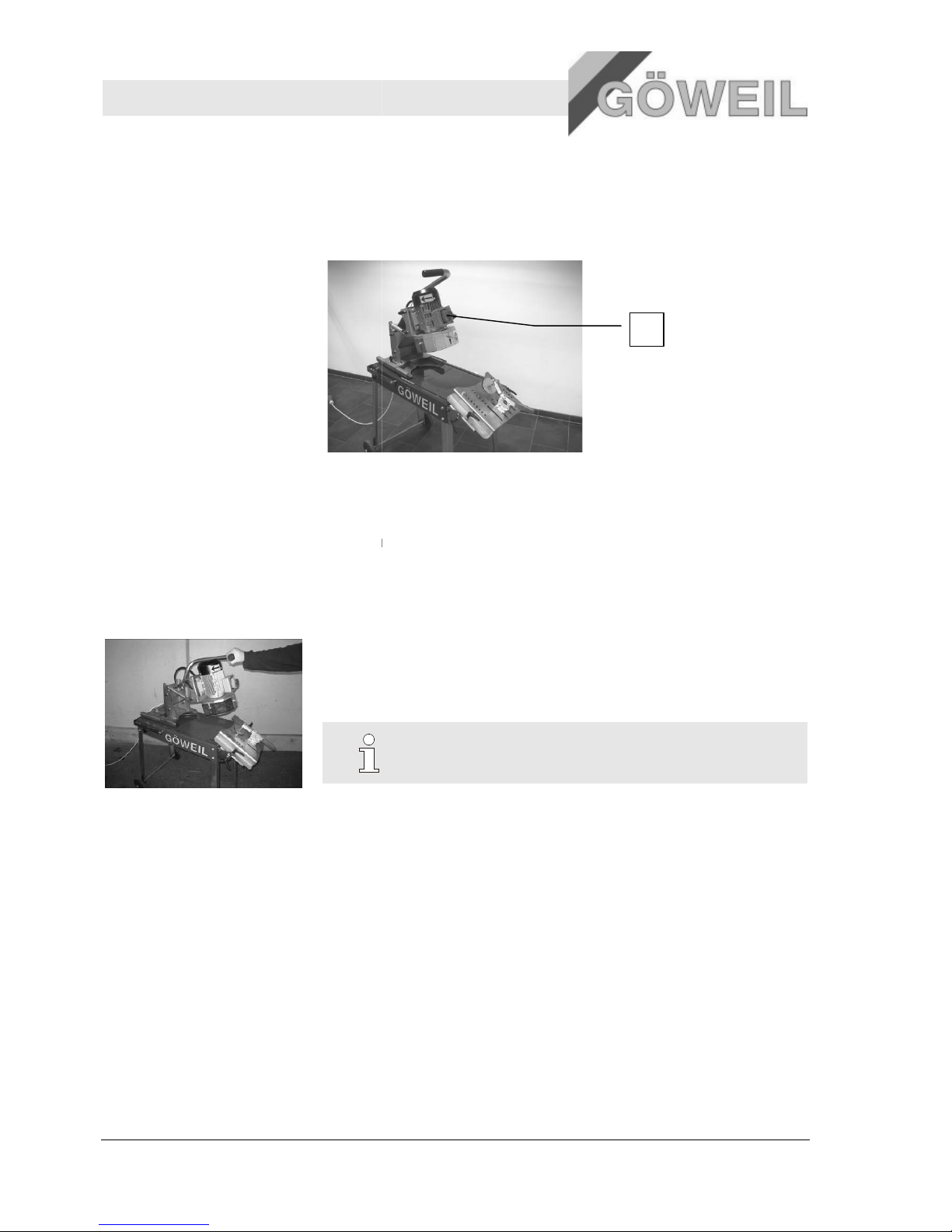
Knife sharpener MS 100
Design and function
16
4.5 Position of the
emergency stop buttons
4.5.1 Overview
The machine is equipped with one emergency stop button. Pressing this button will switch off the machine
immediately.
1
Emergency stop button on the motor
4.6 Controls
The machine is operated using the operating handle.
4.6.1 Operating handle
The operating handle can be used to perform the following functions:
Lowering and lifting the grinding unit
Rotary movements for grinding the
4.7 Operating modes
Manual operation (using the operating handle)
Rotary movements for grinding the knives
NOTICE!
For explanations on the operating handle, [→ se
e chapter "6.
Operation – page 17"].
1
10.03.2009
Page 53
Knife sharpener MS 100
Transport, packaging
10.03.2009 17
5 Transport, packaging
5.1 Transport inspection
Check the shipment for completeness and transport damage immediately upon receipt.
Proceed as follows when detecting any obvious transport damage:
Do not accept the shipment at all or only under protest.
Note the extent of the damage on the transport documents or the carrier's delivery note.
Initiate a complaint.
NOTICE!
Report every defect as soon as you detect it. Claims for damages can be accepted if filed
within the applicable period for filing complaints.
5.2 Packaging
Handling
packaging
materials
Dispose of packaging material in accordance with all applicable statutory provisions and local regulations.
CAUTION!
Environmental damage due to improper disposal!
Packaging materials are valuable resources and can often be reused or reprocessed and
recycled in a sensible manner.
Therefore:
– Dispose of packaging materials in an environmentally safe manner.
– Comply with all applicable local waste disposal regulations. If necessary, use the
services of a professional waste disposal company.
6 Operation
6.1 Safety
Personal
protective
equipment
Always wear the following protective equipment when operating the machine:
Protective clothing
Safety shoes
Safety goggles
Hearing protection
Stability
WARNING!
Risk of injury due to insufficient stability!
Insufficient stability of the machine during operation may lead to serious injury.
Therefore:
– Always position the machine on a stable, dry and level surface and secure it from rolling
away.
Page 54

Knife sharpener MS 100
Operation
18 10.03.2009
Safety
distance
WARNING!
Risk of injury due to insufficient safety distance!
Keeping an insufficient distance to the hazard areas of the machine may lead to injury.
Therefore:
– Always keep a great enough safety distance from the hazard areas of the machine.
Pos: 7.8 /KN2006-SM/Bedienung/003 1.1. 0 Grundlegendes @ 9\mod_ 1144402038705 _1.doc @ 8647 6
Improper
operation
WARNING!
Risk of injury due to improper operation!
Improper operation may cause serious personal injury or property damage.
Therefore:
– The machine may only be operated by one person.
– Perform all operating steps following the information provided in the operating
instructions.
– Before beginning to work, make sure that all covers and safety fixtures are installed and
function properly.
– Never disable any safety fixtures during operation.
– Keep the work area tidy and clean! Components lying loosely about or on top of each
other may lead to accidents.
6.2 Initial operation
The machine has only been partially assembled by the manufacturer.
1. Take the machine out of its packaging and assemble it following the included drawing "Assembly MS 100".
Tightening torque for M6 => 10Nm
Tightening torque for M8 => 25Nm
2. Check the cup grinding wheel for damages.
3. Attach the power plug.
Select the power plug that matches the model of the motor and the country in which the machine is used.
WARNING!
Risk of injury due to improper installation of the electrical system!
The installation has to be performed by a trained electrician!
We strongly recommend that you protect the corresponding connection from moisture and contamination.
Page 55
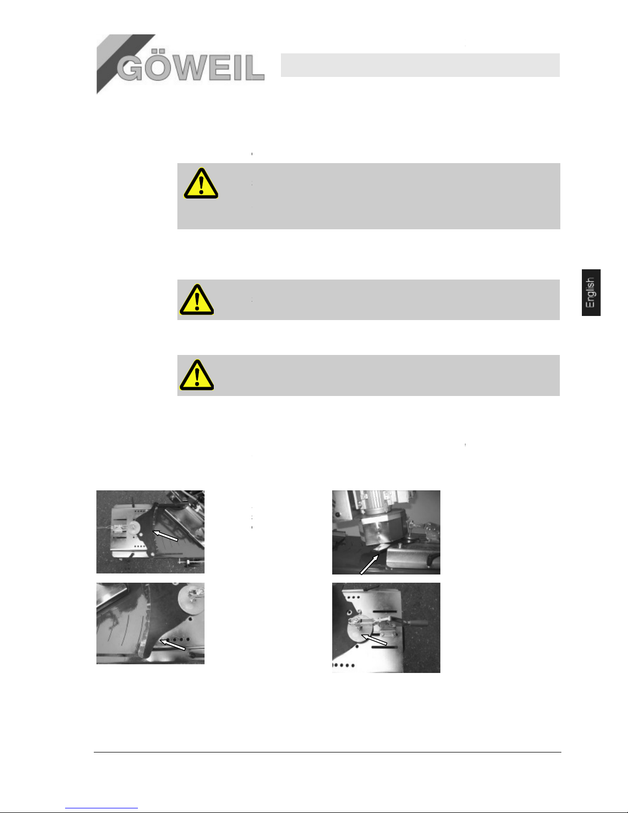
10.03.2009
6.3 Preparations
Pos: 7.9 /KN2006-SM/nL.......... Seitenumbruc h .......... @ 8\mod _11419983347 03_0.doc @ 7548 9
6.3.1 Startup
1.
Place the machine on a stable and level surface.
WARNING!
Risk of injury due to incorrect setup!
Setting the machine up improperly may lead to serious
Therefore:
–
Make sure there is sufficient room to operate the machine.
2
. Attach the power plug
Plug the power plug into the designated socket.
WARNING!
Risk of electric shock when handling cables improperly!
3
. Check the cup grinding wheel
WARNING!
Always check the cup grinding wheel before starting up the machine!
6.4 Positioning curved
kniv
Pos: 7.18 /KN2006-SM/Bedienung/007 1.1 Still setzen im Notfall -- > Anlage und grö ssere Masc hine @ 9\mod_11 44432835796 _1.doc @ 86788
In dangerous situations, the movements of the machine must be stopped and the power supply cut off as
quickly as possible.
Also make sure that the curved
rests safely against the end stop bolts.
1.
The curved
securely placed in the
center of the adjusting
plate. Smooth cutting
surface at the top,
serrated edge at the
bottom.
3.
Position the end stop
bolts as far out as
possible and fix them in
place.
Knife sharpener
injuries.
es
knife
is securely clamped into the
knife must be
2.
4.
MS 100
Operation
19
clamping device and
The cutting surface must
protrude by approx. 0.79
in from the adjusting
plate.
Position the clamping
device in such a way that
the knife holder securely
clamps the curved knife
you want to sharpen
(approx. half of the
overlap)
Page 56
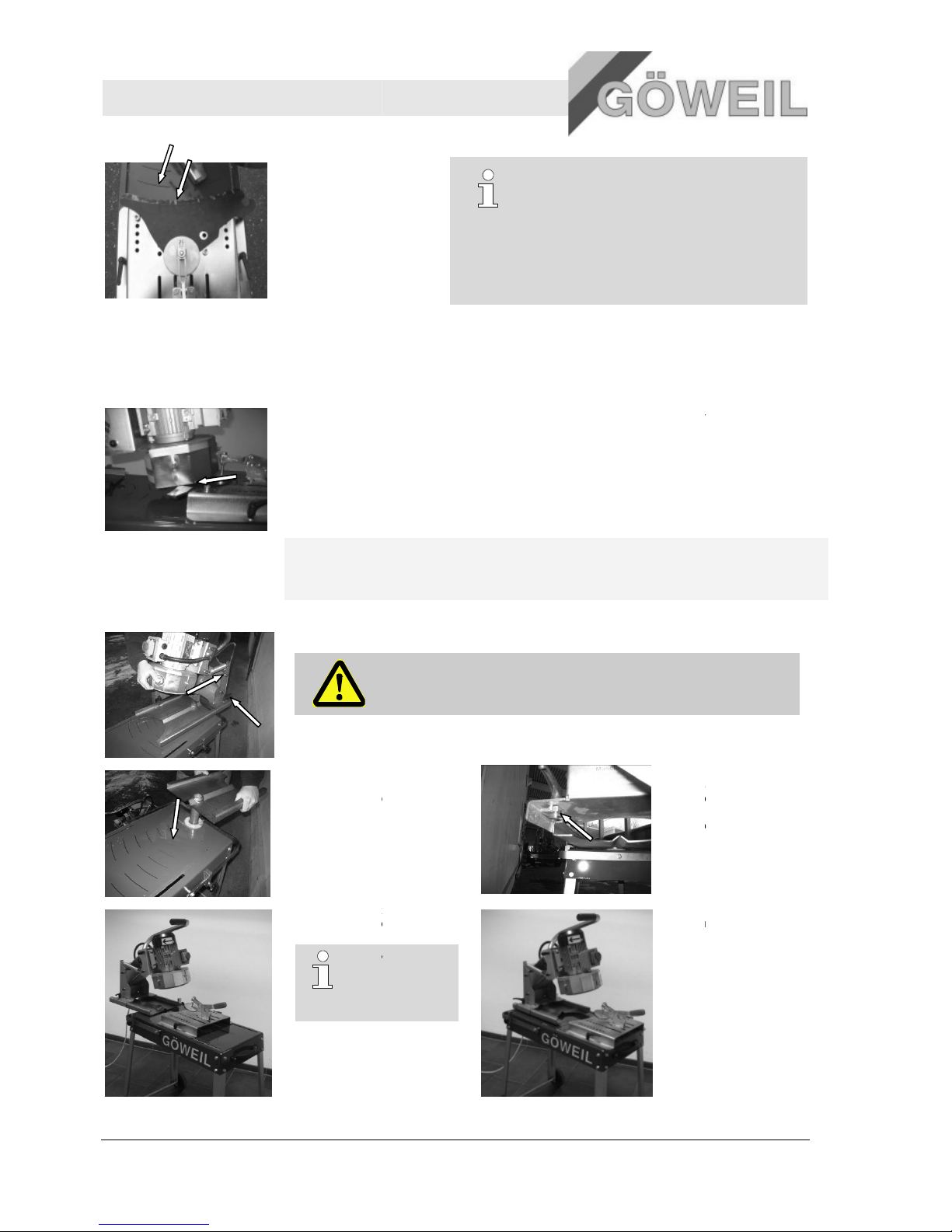
Knife sharpener MS 100
Operation
20
5.
Move the adjusting place
until the knife
radius
matches the radius dial
and fix it in place.
6.5
Adjusting the grinding unit
Pos: 7.18 /KN2006-SM/Bedienung/007 1.1 Still setzen im Notfall -- > Anlage und grö ssere Masc hine @ 9\mod_11 44432835796 _1.doc @ 86788
Adjust the grinding unit so that the cup grinding wheel is exactly in the center of the access (see
photo below).
.
Also make sure that the curved
device and rests safely against the end stop bolts.
The distance between the safety plate of the cup grinding wheel and the curved
short as possible.
In order to be able to grind both ver
the grinding unit by 180°.
To do so, perform the following steps:
1.
Loosen the clamping lever and slide the entire grinding unit to the back before taking it off.
2.
Lift the rotary unit out of
the guide and turn it by
180°. Reinsert the rotary
unit. From the rear, slide
the grinding unit back onto
the rotary unit before
adjusting it and fixing it in
place.
4.
Position of the rotary unit
for small
radii.
TIP!
Most
require that you
set the rotary unit
as shown here.
TIP!
We recommend that you mark the outline of the
back edge on the adjusting plate. This will later
make it easier to position the
knife
sharpen.
knife is securely clamped into the horizontal clamping
y small and very large radii, you can turn the rotary unit of
ATTENTION!
When
taking off the grinding unit, make sure it does not slip out of your
hands – RISK OF INJURY!!
3.
When doing so, make
sure that the clamping
plates are properly
inserted at the bottom
of the grinding unit!
knives
5.
Position of the rotary
unit for
10.03.2009
you want to
knife must be as
large radii.
Page 57
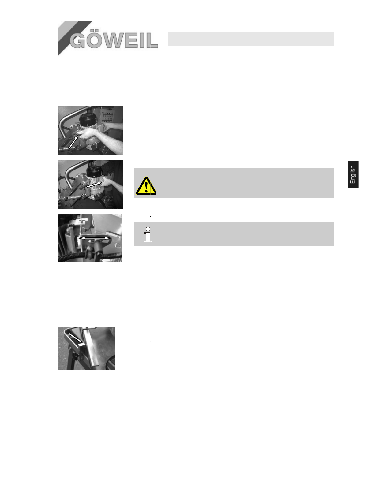
10.03.2009
6.6
Adjusting the grinding angle
Pos: 7.18 /KN2006-SM/Bedienung/007 1.1 Still setzen im Notfall -- > Anlage und grö ssere Masc hine @ 9\mod_11 44432835796 _1.doc @ 86788
As it is different for the different types of
The following steps are necessary:
.
device and rests safely against the end stop bolts.
1.
Loosen the clamping lever on one side.
2.
Hold the electric motor with one hand while loosening the second clamping lever.
3.
Adjust the grinding angle before retightening both clamping levers.
6.7
Adjusting the rotation limiter
Pos: 7.18 /KN2006-SM/Bedienung/007 1.1 Still setzen im Notfall -- > Anlage und grö ssere Masc hine @ 9\mod_11 44432835796 _1.doc @ 86788
The rotation limiter (end stop) must be set in such a way that the cup grinding wheel remains inside
the cutting surface and does not grind over the edge at the beginning or the end of the
The adjustment can be made for each
1.
Undo the
2.
Make the adjustment.
3.
Retighten the star screw.
6.8 Operation
Personal protective
equipment
Always wear the following protective equipment when operating the machine:
Protective clothing
Safety shoes
Safety goggles
Hearing protection
Knife sharpener
knive
s, the grinding angle must be adjustable.
Also make sure that the curved
knife is securely clamped into the horizontal clamping
ATTENTION!
When opening
the second clamping lever, hold the electric motor only at
the front, as there is a RISK OF INJURY at the rear!!
TIP!
Setting the right grinding angle is easier for new knive
s.
knife.
star screw.
MS 100
Operation
21
knife.
Page 58
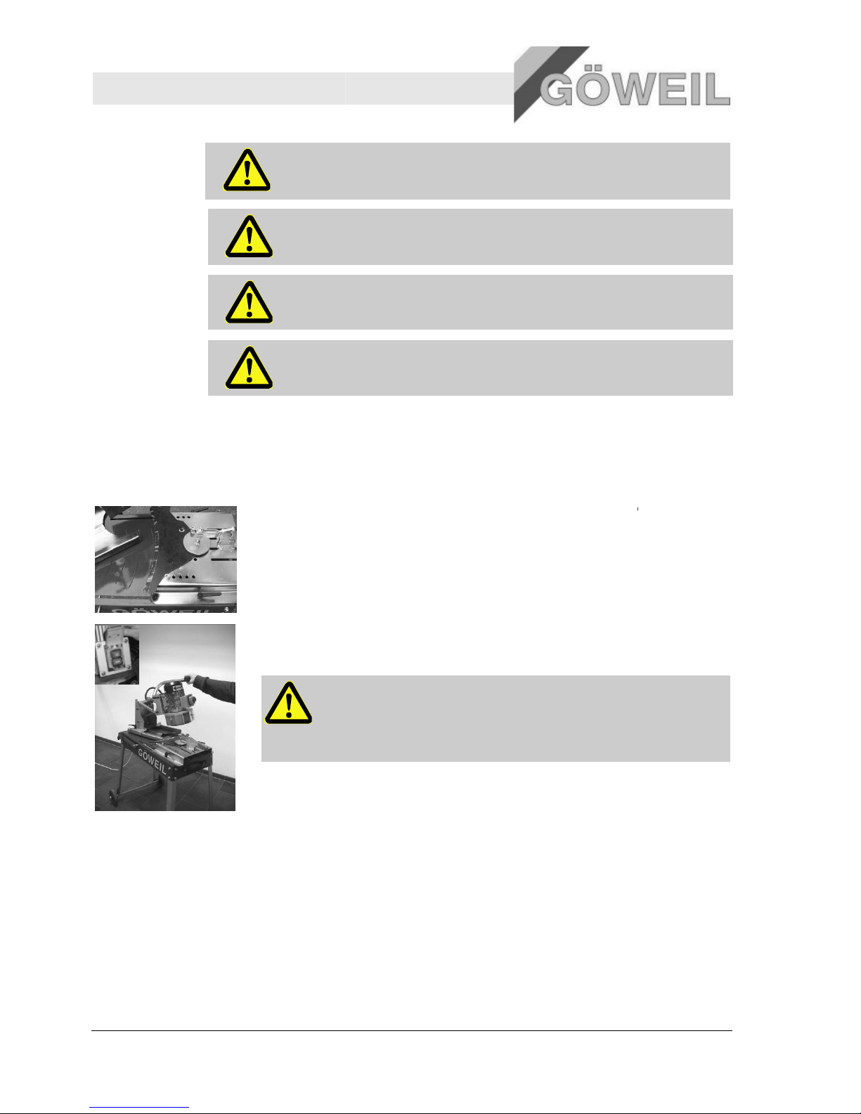
Knife sharpener MS 100
Operation
22
Information
ATTENTION!
Get to know all elements of the
carefully before placing the machine in operation!
Starting torque
ATTENTION!
Great starting torque of the
when turning the machine on.
Changing
knifes
ATTENTION!
Knive
s must not be changed unless the cup grinding wheel is at a standstill.
Grinding
surface
ATTENTION!
Never touch the ground
sharp and hot! GREAT RISK OF INJURY!
6.8.1
6.8.1 Operating sequence
Follow this sequence when sharpening different
.
Also make sure that the curved
device and rests safely against the end stop bolts.
1.
Position and securely clamp the curved
knives."
.
Also make sure that the curved
device and rests safely against the end stop bolts.
2.
Use the green switch (I) on the emergency stop button to turn the motor on while
to the operating handle
3.
Grind the curved
4.
Repeat the grinding process until the
5.
Switch the electric motor off, wait until the cup grinding wheel has come to a standstill, remove
the curved
knife
19
, item 6.4 "Positioning curved
knife
sharpener and read the operating manual
electric motor. Therefore, hold on to the operating handle
surface when the grinding process is complete as it is very
knives:
knife is securely clamped into the horizontal clamping
knife. See page 19
, item 6.4 "Positioning the curved
knife is securely clamped into the horizontal clamping
.
knife using regular right-left movements!
ATTENTION!
Do not apply too much grinding pressure! Using too much grinding
pressure will decrease the grade of the knife
(blue coloration of the
grinding surface).
Watch out for flying sparks!
knife is fully sharpened!
and clamp in the next knife
to be sharpened following the instructions on
knifes".
10.03.2009
holding on
page
Page 59
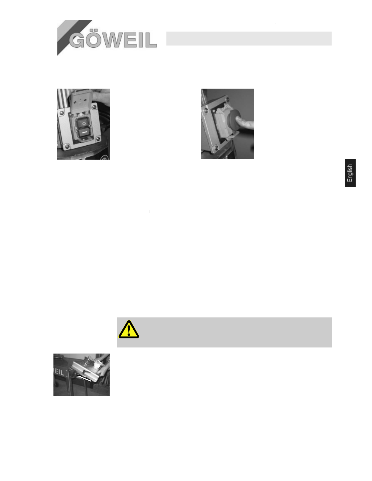
10.03.2009
6.9
Switching the machine off
1.
Switch the machine off using the
OFF switch (red button "0").
6.10
Linear grinding unit (additional equipment)
The linear grinding unit can be used to sharpen straight
Sharpening straight
knife
and mount it on the angle table of the linear grinding unit.
6.10.1
Attaching the linear grinding unit
See drawing "Attaching linear grinding unit"
Tightening torque for M6 => 10Nm
Tightening torque for M8 => 25Nm
6.10.2
Adjusting the linear grinding unit
Make the adjustments as described
rotation limiter"
.
.
Also make sure that the curved
and rests safely against the end stop bolts.
1.
Align the linear grinding unit according to the grinding angle. Both angle straps have four recesses
each.
The topmost recess is equal to 0 degrees (horizontal) on the angle table. The other recesses are
positioned in 15 degree increments.
Undo
quick
Knife sharpener
2.
Press the lockable cover of
the emergency stop switch
closed until it
place.
3.
Pull the power plug.
knives.
s merely requires that you remove
the adjusting plate from the grinding table
.
.
on pages 19, item 6.
3 "Preparations" to 21
IMPORTANT!
When sharpening straight knive
s, make sure the surface to be ground is
horizontal. This means that the cup grinding wheel must be aligned horizontally
as well!
knife is securely clamped into the horizontal clamping device
-action locking screws – adjust angle – tighten quick-
action locking screw.
MS 100
Operation
23
locks into
, item 6.7 "Adjusting the
Page 60
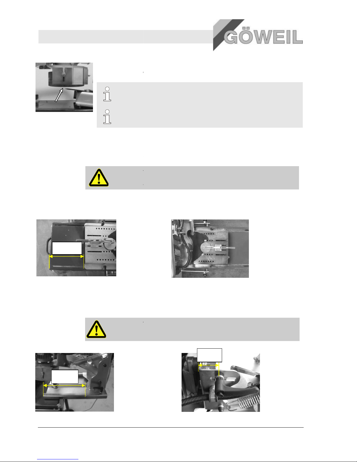
Knife sharpener MS 100
Operation
24
.
Also make sure that the curved
and rests safely against the end stop bolts.
2.
Level the cup grinding wheel an
21
, item 6.6 „Adjusting the grinding angle“)
3.
The work flow is the same as described
NOTICE!
If not needed, the linear grinding unit can be folded
TIP!
Setting the right grinding angle is easier for new
6.11 Positioning knive
s for Krone VP 1500 and VP 1800 round bale presses
Shown below are special setting specifications for
presses!
IMPORTANT!
The specifications below are guide values as they may vary slightly depending on
the wear on the
6.11.1 Setting the adjusting plate/
knife
The
specified dimension is merely intended as a guide value!
6.11.2 Adjusting the grinding unit
6.11.2.1 Retaining plate –
adjusting distance, grinding angle
IMPORTANT!
You must turn the rotary unit
“Adjusting the grinding unit“
The specified dimensions are merely intended as guide values!
275mm
270 mm
knife is securely clamped into the horizontal clamping device
d the cutting surface into a horizontal position (0 degrees) (
on page 22, item 6.8.1 "Work flow".
away.
knives.
knives used in
Krone VP 1500 and VP 1800 round bale
knives!
position on the adjusting plate
Correct position of the knife!
of the grinding unit by 180°! See page
20
40mm
10.03.2009
page
, item 6.5
Page 61

22
Knife sharpener MS 100
Faults
19.02.2009 25
7 Faults
The following chapter describes possible causes of faults and steps to correct them.
If faults occur with great frequently, shorten the maintenance intervals according to the actual stress.
If faults cannot be corrected following the instructions listed below, contact an authorized dealer close to you or
the manufacturer.
7.1 Safety
Personnel
Unless specified otherwise, the troubleshooting steps described herein can be performed by the
operator.
Some steps may only be performed by specially trained qualified personnel or the manufacturer.
These steps will be pointed out separately in the description of the individual faults.
All work on the electrical system must be performed by trained electricians.
Personal
protective
equipment
Wear the following protective equipment during all troubleshooting operations:
Protective clothing
Safety shoes
Safeguard
against restart
DANGER!
Risk of fatal injury caused by unauthorized restart!
Troubleshooting operations always involve the risk of the power supply being switched
on without authority. This may cause fatal injuries to any person inside the hazard area
of the machine.
Therefore:
– Switch off the power supplies and secure them against restart before commencing
any work
– Pull the power plug.
Improper
troubleshooting
WARNING!
Risk of injury due to improper troubleshooting!
Improper troubleshooting may cause serious personal injury or property damage.
Therefore:
– Before beginning to work, provide for enough installation clearance.
– Keep the installation site tidy and clean! Components lying loosely about or on top
of each other may lead to accidents.
– Make sure that all previously removed components and all fasteners are reinstalled
properly and all screws are tightened to torque.
– Install all covers and safety fixtures as prescribed and check if they function
properly.
Page 62

Knife sharpener MS 100
Faults
26 10.03.2009
Behavior in
the event of
faults
Basically the following applies:
1. Trigger the emergency function immediately in the event of faults that may cause personal injury or
property damage.
2. Find the cause of the fault.
3. If troubleshooting requires work in the hazard area, switch the machine off and secure it against
unauthorized restart.
4. Immediately notify the person in charge on site about the fault.
5. Depending on the type of the fault, correct the fault yourself or have it corrected by an authorized and
trained expert.
NOTICE!
The table of faults shown below specifies who is authorized to correct the fault.
7.2 Table of faults
7.2.1 General faults
Fault Possible cause Remedy To be corrected by
Electric motor without
function
Electric power supply
missing
Attach the supply cable to the machine. Operator
Defective fuse Replace the fuse in the control cabinet. Trained electrician
Damaged connecting cable Replace the connecting cable. Trained electrician
Electric motor turns off
after a short period of
time.
Thermal protection tripped /
active
Check the plug.
Is the electric motor connected properly as
specified in the circuit diagram?
Trained electrician
Cup grinding wheel
vibrates
Unbalance, parts broken out Replace Operator
7.3 Troubleshooting
7.3.1 Replacing the cup grinding wheel
IMPORTANT!
The cup grinding wheel must be used as specified by the manufacturer!
The cup grinding wheel may only be replaced by instructed operating
personnel!
The cup grinding wheel may only be used up to the end of the adjusting
range of the adjustable safety plate!
Page 63
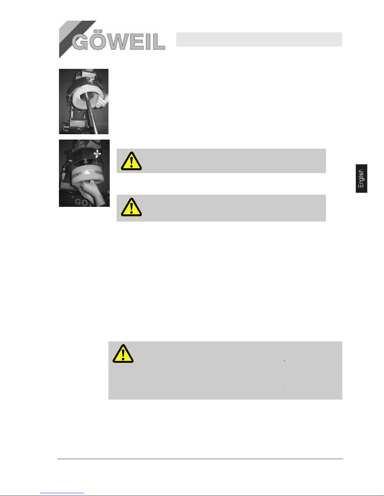
10.03.2009
.
Also make sure that the curved
rests safely against the end stop bolts.
1.
Unscrew the cup grinding wheel on the bottom using a suitable tool and hold it with one hand.
.
Also make sure that the curved
rests safely against the end stop bolts.
2.
Pull the cup grinding wheel including the spring washer off the motor axle.
IMPORTANT!
3.
Slip the new cup grinding wheel including the spring washer onto the motor axle and tighten it.
Tightening torque for M8 => 25Nm
DANGER!
8 Maintenance
Pos: 9.3 /KN2006-SM/Wartung/002 1 Sicherh eit_Titel @ 9\mo d_114443483 1619_1.doc @ 8681 0
8.1 Safety
Pos: 9.4 /KN2006-SM/Wartung/003 1.1.0 Personal --> Standard --
> ggf. anpassen @ 9
Personnel
Unless specified otherwise, the maintenance steps des
Some maintenance steps may only be performed by specially trained qualified personnel or the
manufacturer. These steps will be pointed out separately in the description of the individual maintenance
steps.
All work on the electrical system must be performed by trained electricians.
Personal
protective
equipment
Wear the following protective equipment when performing maintenance:
Protective clothing
Safety shoes
Safeguard
against restart
DANGER!
Risk of fatal injury caused by unauthorized restart!
Performing maintenance work always involves the risk of the power supply being switched
on without authority. This may cause fatal injuries to any person
the machine.
Therefore:
–
Knife sharpener
knife is securely clamped into the horizontal clamping device and
knife is securely clamped into the horizontal clamping device and
Mark the cup grinding wheel as used and dispose of it!
.
The new cup grinding wheel must not be exposed to blows!
RISK of bursting during operation!
\mod_1144434832402_1.doc @ 86817
cribed herein can be performed by the operator.
inside the hazard area of
Switch off all power supplies and secure them against restart before commencing any
work.
MS 100
Maintenance
27
Page 64

Knife sharpener MS 100
Maintenance
28 10.03.2009
Spring tension
CAUTION!
Risk of injury due to recoiling lever!
Levers under spring tension may cause injury.
Therefore:
– Use caution when working on levers under spring tension.
– Keep at a safe distance.
Environmental
protection
Observe the following environmental information when performing maintenance:
Remove any used, excess or exiting grease from all lubricating points that are manually supplied with
lubricant and dispose of the grease as required by all applicable local regulations.
8.2 Maintenance schedule
The following sections describe maintenance steps that need to be performed to allow the machine to operate
trouble free and at its full capacity.
If regular inspections reveal an increased level of wear, the maintenance intervals must be shortened in
accordance with the actual wear detected.
For questions about maintenance steps and intervals, please contact the manufacturer or an authorized dealer.
Interval
(Bh – hours
of operation)
Maintenance step To be performed by
General
Prior to every
use
Remove any foreign objects and contamination. Operator
Movability of components Operator
Condition of the cup grinding wheel Operator
Wear on the cup grinding wheel Operator
annually Lubricate the pilot bearing of the rotary unit. Operator
8.3 Maintenance steps
8.3.1 Lubricating joints
Other required protective equipment:
Protective gloves
Page 65
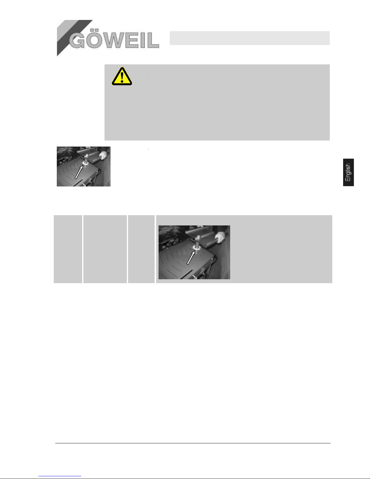
10.03.2009
Lubricants
WARNING!
Risk of fire, poisoning, and health damage caused by lubricants!
Lubricants may ignite when coming into contact with sources of ignition.
Contact with oil and grease may cause
Therefore:
–
No open fire during work on the machine.
–
Do not smoke.
–
Do not inhale oil or grease fumes.
–
Avoid skin contact with oil and grease.
–
Immediately clean the skin of all oil and grease.
Only the pilot
multipurpose grease.
8.4 Lubrication chart
annually Pilot bearing of the
rotary unit
1 bearing
8.5
Steps after maintenance is
Pos: 9.33 /KN2006-SM/Wartung/009 1.1.0 Mass nahmen nach erfolgter Wartung - -> Standard @ 9\mod_114443 8981309_1.doc @ 86935
Proceed as follows when maintenance is complete and before switching the machine back on:
1.
Check if all previously loosened
2.
Check if all previously removed safety fixtures and covers have been properly reinstalled.
3.
Make sure that all tools, materials and other equipment used have been removed from the work area.
4.
Clean the work area and remove any le
materials.
5.
Ensure that all safety fixtures of the machine function properly.
Knife sharpener
damage to a person's health.
bearing of the rotary unit on the grinding machine has to be lubricated with standard
Clean the pilot bearing first!
complete
screw connections are tight.
aked materials such as liquids, process materials or similar
MS 100
Maintenance
29
Page 66

Knife sharpener MS 100
Disassembly
30 10.03.2009
9 Disassembly
Pos: 10.3 /KN2006-SM/Demontage/001 1. 0 Nachdem das G ebrauchsend e erreicht ist. ..(Anlage) @ 9\m od_11445018 94460_1.doc @ 87460
When it has reached the end of its service life, the machine must be disassembled and disposed of in an
environmentally safe manner.
Pos: 10.4 /KN2006-SM/nL---------- Abschnittsende ---------- @ 8\mod_1141997892953_0.doc @ 75471
NOTICE!
Disassembly must be performed by qualified personnel.
WARNING!
Danger due to incorrect disassembly!
The personnel disassembling the machine must be trained and qualified and have sufficient
experience. Errors made during disassembly may cause life-threatening situations or
significant property damage.
Therefore:
– Have the machine disassembled by members of the manufacturer's staff only.
– Do not disassemble the machine without authorization.
9.1 Disposal
Unless a return or disposal agreement has been made, recycle dismantled components as follows:
Scrap metals.
Recycle plastic components.
Dispose of all other components in accordance with the material of which they consist.
CAUTION!
Environmental damage due to improper disposal!
Waste electrical and electronic equipment, lubricants and other process materials must be
treated as hazardous waste and disposed of by authorized waste management companies only!
Contact your local authorities or special waste management companies for information on environmentally safe
disposal.
Pos: 11.1 /KN2006-Projekte/Rüfenacht/Ers atzteilliste/1 Ersa tzteile - Titel @ 47\mod_ 1190042012578 _1.doc @ 623734
Page 67

Knife sharpener MS 100
Spare parts/Appendix
10.03.2009 31
10 Spare parts
Pos: 11.2 /KN2006-Projekte/Uviterno/UV - Tro cknungss ysteme/Ersatzteillist e/1.0 Nur Orig inal-Ersatzteile verwenden-U V-Trockner @ 49\mod_11932 37144634_1.d oc @ 762140
WARNING!
Risk of injury due to incorrect spare parts!
Wrong or defective spare parts may impact safety and lead to damage, malfunctions or
complete failure.
Therefore:
– Use only original spare parts made by the manufacturer.
Purchase spare parts from authorized dealers or directly from the manufacturer. A replacement parts list is
included in the appendix. Using unapproved spare parts will void all warranty and service claims.
Pos: 11.3 /KN2006-SM/nL--------- - Abschnittsende ------ ---- @ 8\mod_11 41997892953_0 .doc @ 75471
10.1 Ordering spare parts
Pos: 11.5 /KN2006-Projekte/Uviterno/UV - Tro cknungss ysteme/Ersatzteillist e/1.1 Ersatzt eilbestellung - T ext-UV-Troc kner @ 49\mod _1193237232 019_1.doc @ 762228
When ordering spare parts, please always include:
Designation
Type
Year of manufacture
Item number as specified in the replacement parts list included in the appendix
Quantity
desired type of shipping (mail, cargo, sea, air, express)
Shipping address
We cannot process spare part orders that do not include this information. If the desired type of shipping is not
specified, the type of shipping is at the discretion of the manufacturer/supplier.
11 Appendix
SM/nL.......... Seitenumbruch .......... @ 8\ mod_11419983 34703_0.doc @ 75489
Pos: 12.3 /KN2006-Projekte/NSD Lift AG/A nhang/1.1 Inhal t @ 54\mod_ 1196948759959 _1.doc @ 8758 50
11.1 Third-party documents
Components Designation Type Manufacturer
Electric motor (400V) Three-phase squirrel cage
motor
Y3-80B2 KEDU KJD18 Moll-Motor
Electric motor (230V) Single-phase motor Y3E-80B2 KEDU KJD18 Moll-Motor
11.2 Replacement parts lists / Assembly drawings / Circuit diagrams
See appendix
Page 68

Page 69

Manuel d'utilisation
Affûteur
MS 100
Page 70

Déclaration de conformité CE
conformément à la directive de la Communauté Européenne 98/37/CE
GÖWEIL MASCHINENBAU GmbH
( Nom du fournisseur)
A-4202 Kirchschlag, Eben 128
(Adresse complète de la société ; pour le fondé de pouvoir installé dans la communauté également l'indication de
la société et l'adresse du constructeur)
déclarons sur notre seule resonsabilité que le produit
Affûtteur MS 100
(Modèle, type)
auquel la présente déclaration fait référence, correspond aux exigences fondamentales sur
la sécurité et la santé de la directive 98/37/CE,
(si fondé)
ainsi qu'aux exigences des autres directives CE correspondantes
Directive machine 98/37/CE, annexe 1
Directive machine 2006/42/CE, transposée dans la législation autrichienne
par la parution dans le Journal Officiel I No 8/2008 dans sa version en
vigueur
Directive basse tension 2006/95/CE
(Titre et/ou numéro ainsi que la date d'édition des autres directives CE)
(si fondé)
Les normes ou spécifications techniques sont prises à contribution pour la mise en pratique
appropriée des exigences de sécurité et de santé mentionnées dans les directives CE :
EN 294; EN 349; EN 547-1; EN 614-1; EN 563; EN 894; EN 953;
EN ISO 13849 – 1; EN 999; EN 1037; EN ISO 12100; EN 13850;
EN ISO 14121; EN 60204-1
(Titre et/ou numéro ainsi que la date d'édition des normes et/ou des spécifications techniques)
Kirchschlag, le 10.03.2009 Herbert Göweil, gérant
(Lieu et date de délivrance) (Nom, fonction et signature de la personne autorisée)
Page 71

Affûteur MS 100
Sommaire
10.03.2009 1
1 Généralités ................................................................................................... 3
1.1 Informations relatives à ce manuel .................................................... 3
1.2 Explication des symboles .................................................................. 3
1.3 Limite de responsabilité ..................................................................... 4
1.4 Droit de propriété industrielle ............................................................. 4
1.5 Pièces de rechange........................................................................... 4
1.6 Dispositions relatives à la garantie .................................................... 4
1.7 Service après-vente .......................................................................... 4
2 Sécurité ........................................................................................................ 5
2.1 Utilisation conforme à la destination .................................................. 5
2.2 Responsabilité de l'exploitant ............................................................ 5
2.3 Spécifications relatives au personnel ................................................. 6
2.4 Equipement personnel de protection ................................................. 7
2.5 Risques particuliers ........................................................................... 8
2.6 Dispositifs de sécurité ....................................................................... 9
2.7 Sécurisation contre toute remise en marche .................................... 11
2.8 Attitude à adopter en cas de danger et d'accidents ......................... 11
2.9 Protection de l'environnement ......................................................... 12
2.10 Signalisation .................................................................................... 12
2.11 Symboles d'avertissement ............................................................... 12
2.12 Modifications ................................................................................... 12
3 Spécifications techniques ......................................................................... 13
3.1 Informations générales .................................................................... 13
3.2 Puissances connectées ................................................................... 13
3.3 Conditions de service ...................................................................... 14
3.4 Emissions........................................................................................ 14
3.5 Consommables ............................................................................... 14
3.6 Plaque signalétique ......................................................................... 14
4 Structure et fonction ................................................................................. 15
4.1 Aperçu ............................................................................................ 15
4.2 Description brève ............................................................................ 15
4.3 Connexions ..................................................................................... 16
4.4 Périmètres de travail et de danger ................................................... 16
4.5 Emplacement du bouton d'arrêt d'urgence ...................................... 17
4.6 Eléments de commande .................................................................. 17
4.7 Modes de fonctionnement ............................................................... 17
5 Transport, emballage ................................................................................ 18
5.1 Inspection après le transport ........................................................... 18
5.2 Emballage ....................................................................................... 18
6 Utilisation ................................................................................................... 18
6.1 Sécurité ........................................................................................... 18
6.2 Première mise en service ................................................................ 19
6.3 Préparatifs ....................................................................................... 19
6.4 Positionner le couteau courbé ......................................................... 20
6.5 Régler l'unité d'affûtage ................................................................... 20
Page 72

00
Affûteur MS 100
Sommaire
2 10.03.2009
6.6 Régler l'angle d'affûtage .................................................................. 22
6.7 Régler le limiteur de rotation ............................................................ 22
6.8 Fonctionnement ............................................................................... 23
6.9 Arrêter la machine ........................................................................... 24
6.10 Unité d'affûtage linéaire (option) ...................................................... 24
6.11 Positionner les couteaux pour la presse à balles rondes Krone VP
1500 et VP 1800 .............................................................................. 25
7 Pannes et anomalies .................................................................................. 26
7.1 Sécurité ........................................................................................... 26
7.2 Table des pannes ............................................................................ 27
7.3 Élimination des dérangements ......................................................... 27
8 Entretien ..................................................................................................... 28
8.1 Sécurité ........................................................................................... 28
8.2 Planning de maintenance................................................................. 29
8.3 Travaux de maintenance ................................................................. 29
8.4 Intervalles de graissage ................................................................... 29
8.5 Mesures après maintenance ............................................................ 29
9 Démontage ................................................................................................. 31
9.1 Elimination ....................................................................................... 31
10 Pièces de rechange .................................................................................... 32
10.1 Commande de pièces détachées ..................................................... 32
11 Annexe ........................................................................................................ 32
11.1 Documents tiers ............................................................................... 32
11.2 Nomenclatures de pièces détachées / Dessins de montage /
Plans des connexions ...................................................................... 32
Page 73
Affûteur MS 100
Généralités
10.03.2009 3
1 Généralités
Pos: 1.2 /KN2006-SM/Allgemeines/110 1.1 Informatione n zur Anleitung (A nlage) @ 9\mo d_114440275 0137_1.doc @ 8 6521
1.1 Informations relatives à ce manuel
Les instructions de ce manuel permettent une manipulation sûre et fiable de la machine :
Le manuel fait partie intégrante de la machine et doit être conservé à proximité immédiate de la machine et être
accessible au personnel. Avant tous travaux, le personnel doit avoir lu scrupuleusement le manuel et l'avoir
compris. La condition préalable d'un travail en toute sécurité est le respect de toutes les consignes de sécurité
et des instructions du manuel.
Les prescriptions de prévention des accidents en vigueur localement et les dispositions générales relatives à la
sécurité du domaine d'application s'appliquent en l'espèce.
Les illustrations du manuel servent à une meilleure compréhension et peuvent varier de la version effective de
la machine.
Outre le présent manuel, les instructions en annexe de composants rapportés s'appliquent.
1.2 Explication des symboles
Consignes de
sécurité
s consignes de sécurité sont repérées dans le manuel par des symboles. Les consignes de
sécurité sont introduites par des mots repère qui signalent l'importance du danger.
Respecter absolument les consignes de sécurité et agir avec précaution pour prévenir les accidents
ainsi que les dommages corporels et matériels.
DANGER !
… signale une situation dangereuse directe pouvant occasionner la mort ou de graves lésions,
si elle ne peut pas être évitée.
AVERTISSEMENT !
… signale une situation dangereuse potentielle pouvant occasionner la mort ou de graves
lésions, si elle ne peut pas être évitée.
PRECAUTION !
… signale une situation dangereuse potentielle pouvant occasionner des lésions mineures, si
elle ne peut pas être évitée.
PRECAUTION !
… signale une situation dangereuse potentielle pouvant occasionner des dommages
matériels, si elle ne peut pas être évitée.
Conseils et
recommandations
INDICATION !
... souligne des conseils et recommandations ainsi que des informations pour un
fonctionnement fiable et sans dysfonctionnements.
Consignes de
sécurité
particulières
Pour attirer votre attention sur des risques particuliers, les symboles suivants sont utilisés dans les
consignes de sécurité :
… signale des dangers dus au courant électrique. En cas de non respect des consignes de
sécurité, il y a risque de blessures graves voire mortelles.
Page 74

00
Affûteur MS 100
Généralités
4 10.03.2009
1.3 Limite de responsabilité
Toutes les informations et remarques de ce manuel tiennent compte des normes et prescriptions en vigueur, du
niveau de la technique ainsi que de nos connaissances et expériences acquises au cours des années.
Le fabricant n'endosse aucune responsabilité pour les dommages dus
au non respect des instructions
à une utilisation non conforme à la destination
à l'intervention d'un personnel non qualifié
à des transformations volontaires
à des modifications techniques
à l'utilisation de pièces détachées non autorisées
Les éléments livrés peuvent varier dans les versions spéciales, en cas d'options supplémentaires ou de
modifications techniques récentes par rapport aux explications et illustrations présentes.
Les engagements conclus dans le contrat de livraison, les conditions générales de vente et de livraison du
fabricant ainsi que les réglementations en vigueur à la date de la conclusion du contrat s'appliquent en l'espèce.
Sous réserve de modifications techniques dans le cadre de l'amélioration des produits.
1.4 Droit de propriété industrielle
Les droits de ce manuel sont protégés et ne sont destinés qu'à usage interne.
La transmission du manuel à des tiers, la reproduction, même partielle, sous quelque forme que ce soit ainsi
que l'exploitation et/ou la communication du contenu sont interdites sans l'autorisation écrite du fabricant,
hormis pour usage interne.
Toute infraction donne droit à réparation du dommage. Sous réserve de tous recours.
Pos: 1.14 /KN2006-SM/nL--------- - Abschnittsende ------ ---- @ 8\mod_11 41997892953_0 .doc @ 75471
1.5 Pièces de rechange
AVERTISSEMENT !
Sécurité altérée due à l'emploi de pièces détachées incorrectes !
Les pièces détachées défectueuses ou incorrectes peuvent altérer la sécurité ainsi que
provoquer des dommages, des dysfonctionnements ou des pannes.
Pour cette raison :
– n'utiliser que les pièces détachées d'origine du fabricant
Commander les pièces détachées par l'intermédiaire du concessionnaire ou directement auprès du fabricant.
La nomenclature des pièces détachées se trouve en annexe.
1.6 Dispositions relatives à la garantie
Pos: 1.19 /KN2006-SM/Allgemeines/161 1. 1.0 Garantieb estimmungen i n den AGB des H erstellers @ 9\mod_1144054 766031_1.doc @ 84763
Le fabricant accorde une période de garantie de 1 an.
Pos: 1.20 /KN2006-SM/nL--------- - Abschnittsende ------ ---- @ 8\mod_11 41997892953_0 .doc @ 75471
1.7 Service après-vente
Notre service après-vente se tient à disposition pour toutes informations techniques. D'autre part, nos
collaborateurs sont intéressés en permanence de recevoir des informations résultant de l'application et de la
pratique afin de pouvoir apporter des améliorations à nos produits.
Page 75

Affûteur MS 100
Sécurité
10.03.2009 5
2 Sécurité
Pos: 2.3 /KN2006-SM/Sicherheit/001 1.0 Ein führung @ 8\ mod_1142427 208593_1.doc @ 77470
Ce chapitre fournit un aperçu de tous les aspects essentiels en matière de sécurité pour une protection optimale
du personnel ainsi que pour un fonctionnement sûr et fiable.
Le non respect des instructions de manutention et des consignes de sécurité stipulées dans ce manuel peut
provoquer des dangers substantiels.
2.1 Utilisation conforme à la destination
La machine est conçue et construite exclusivement pour l'utilisation décrite conforme à sa destination.
L'affûteur est destiné exclusivement à l'affûtage de couteaux concaves courbés, doté de l'équipement en
option « unité d'affûtage linéaire » également pour les couteaux droits des presses et chargeuses agricoles.
Toute autre utilisation est considérée comme NON-conforme à la destination. Le fabricant n'est PAS
responsable des dommages ou accidents pouvant en résulter !
Le risque est exclusivement du ressort de l'exploitant. L'utilisation conforme à la destination signifie
également l'observation et le respect des consignes de service, d'entretien et de maintenance édictées par le
fabricant.
AVERTISSEMENT !
Danger dû à une utilisation incorrecte !
Toute utilisation au-delà et autre que celle conforme à la destination de la machine peut
conduire à des situations dangereuses.
Pour cette raison :
– n'utiliser la machine que conformément à sa destination
– respecter strictement les instructions du manuel.
Ne pas utiliser notamment la machine de la façon suivante :
– ne procéder à aucun affûtage qui n'est pas conforme à la destination.
Tout recours de toute nature pour des dommages dus à une utilisation non conforme à la destination est exclu.
2.2 Responsabilité de l'exploitant
La machine est destinée à un usage professionnel et privé. L'exploitant professionnel de la machine est par
conséquent assujetti aux obligations légales en matière de sécurité de travail.
Outre les consignes de sécurité de ce manuel, il faut respecter les prescriptions en vigueur en matière de
sécurité, de prévention des accidents et de protection environnementale pour le domaine d'utilisation de la
machine. On applique notamment :
L'exploitant doit s'informer des dispositions de protection de travail en vigueur et déterminer en plus les
dangers potentiels dans une évaluation des risques résultant des conditions de travail particulières sur le
lieu d'exploitation de la machine. Ceci doit être réalisé sous forme d'instructions pour l'exploitation de la
machine.
Durant tout le temps d'exploitation de la machine, l'exploitant doit contrôler si ses instructions d'exploitation
sont conformes à la législation en vigueur et les adapter le cas échéant.
L'exploitant doit fixer les compétences pour l'installation, la commande, la maintenance et le nettoyage de la
machine.
L'exploitant doit s'assurer que tous les collaborateurs travaillant sur la machine ont lu et compris ce manuel.
Par ailleurs, il doit former à intervalles réguliers le personnel et l'informer des dangers.
L'exploitant doit mettre à disposition du personnel l'équipement de protection nécessaire.
Il est par ailleurs responsable du bon état de marche de la machine. Pour cela, il doit satisfaire les points
suivants :
s'assurer que les intervalles de maintenance stipulés dans ce manuel sont respectés ;
Page 76

00
Affûteur MS 100
Sécurité
6 10.03.2009
faire vérifier régulièrement le bon fonctionnement et l'intégralité de tous les dispositifs de sécurité ;
contrôler avant le transport de la machine que celle-ci est sécurisée.
2.3 Spécifications relatives au personnel
2.3.1 Qualifications
AVERTISSEMENT !
Danger de lésion en cas de qualification insuffisante !
Une manipulation non conforme peut occasionner des dommages corporels et matériels.
Pour cette raison :
– faire exécuter tous les travaux par un personnel qualifié.
Les qualifications suivantes pour les différents travaux sont mentionnées dans le manuel.
Personne instruite
Personne ayant été instruite par le fabricant des tâches qui lui sont confiées et des dangers potentiels en
cas de comportement non conforme.
Personnel spécialisé
Personnel en mesure d'exécuter les travaux qui lui sont confiés ainsi que d'identifier et d'éviter les dangers
potentiels sur la base de sa formation professionnelle, de ses connaissances et expériences et connaissant
les dispositions en vigueur.
Electricien
Personnel en mesure d'exécuter les travaux électriques ainsi que d'identifier et d'éviter les dangers
potentiels sur la base de sa formation professionnelle, de ses connaissances et expériences et connaissant
les normes et dispositions en vigueur.
L'électricien est formé spécialement pour son lieu d'intervention et il connaît les principales normes et
dispositions.
Le personnel ne doit comprendre que des personnes dont on est sûr qu'elles exécutent leur travail
correctement. Sont exclues les personnes âgées de moins de 16 ans ou les personnes sous l'emprise par
ex. de la drogue, de l'alcool ou de médicaments.
Veiller dans le choix du personnel aux dispositions d'âge et professionnelles en vigueur localement.
2.3.2 Personnes non autorisées
AVERTISSEMENT ! Danger pour les personnes non autorisées !
Les personnes non autorisées qui ne satisfont pas les spécifications décrites ici ne
connaissent pas les dangers dans le périmètre de travail.
Pour cette raison :
– Tenir éloignées du périmètre de travail les personnes non autorisées ;
– En cas de doute s'adresser à ces personnes et les éloigner du périmètre de travail ;
– Interrompre les travaux tant que les personnes non autorisées n'ont pas quitté le
périmètre de travail.
Page 77

Affûteur MS 100
Sécurité
10.03.2009 7
2.3.3 Instruction
Le personnel doit être instruit régulièrement par l'exploitant. Afin d'assurer un meilleur suivi de l'instructions,
celle-ci doit faire l'objet de rapports.
Date Nom Nature de l'instruction Instruction dispensée par Signature
2.4 Equipement personnel de protection
Il convient de porter un équipement de protection personnel lors du travail afin de minimiser les risques pour la
santé.
Toujours porter l'équipement de protection durant le travail en fonction de la nature du travail.
Respecter les consignes concernant l'équipement de protection personnel dans le périmètre de travail.
Pos: 2.22 /KN2006-SM/Sicherheit/006 Pers önliche Schutza usstattung/ 006 1.1.0_1 Gru ndsätzlich zu trag en_Titel @ 8\ mod_1143360 998458_1.doc @ 80989
Equipement requis :
Equipement requis pour tous les travaux :
Tenue de protection
Ils doivent être moulants et présenter peu de résistance à la déchirure avec des manches étroites ne dépassant
pas. Elle sert essentiellement à protéger l'ouvrier de tout risque de happage par des pièces mécaniques en
mouvement.
Ne pas porter de bagues, chaînes ou autres bijoux personnels.
Chaussures de sécurité
Elles servent à la protection contre la chute éventuelle de pièces lourdes et préviennent tout risque de dérapage
sur sol glissant.
Casque antibruit
Ce casque protège contre tous les lésions auditives.
Lunettes de protection
Elles sont destinées à protéger les yeux contre toute projection de pièces, éclaboussures de liquide et
d'affûtage.
Gants de protection
Ils assurent la protection des mains contre toute abrasion, écorchure, piqûre, coupure ou lésion plus profonde
ainsi que contre toute brûlure au contact de surfaces chaudes.
Page 78

00
Affûteur MS 100
Sécurité
8 10.03.2009
Pos: 2.27 /KN2006-SM/Sicherheit/006 Pers önliche Schutza usstattung/ 006 1.1.0_2 Bei b esonderen Ar beiten zu tragen _Titel @ 8\mo d_114336112 2656_1.doc @ 8 0999
2.5 Risques particuliers
On trouvera dans le chapitre qui suit une liste de risques résiduels déterminés par une évaluation de risques.
Tenir compte des consignes de sécurité énoncées et des mises en garde figurant d'autres chapitres pour
réduire les risques sanitaires et éviter toutes situations dangereuses.
Pièces en
mouvement
AVERTISSEMENT !
Risque de blessures par des pièces en mouvement !
Les pièces et éléments en rotation ou en mouvement linéaire peuvent occasionner de
graves lésions.
Pour cette raison :
– durant le fonctionnement, ne pas porter la main vers des pièces en rotation et ne pas
séjourner près de ces éléments ;
– ne pas ouvrir les capots durant le fonctionnement ;
– tenir compte du temps nécessaire à l'arrêt complet de l'installation :
Avant le changement des couteaux à affûter, s'assurer qu'aucune pièce n'est en
mouvement ;
– porter une tenue de protection près du corps dans la zone de risque.
Bruit
AVERTISSEMENT !
Lésions auditives dues au bruit !
Le niveau sonore sur le lieu de travail peut entraîner de graves lésions auditives.
Pour cette raison :
– porter par principe un casque antibruit durant le travail ;
– ne pas séjourner plus que nécessaire dans la zone de risques.
Surfaces
brûlantes
PRECAUTION !
Risque de brûlure en cas de contact avec des surfaces brûlantes !
Le contact avec des éléments brûlants peut occasionner des brûlures.
Les couteaux venant d'être affûtés sont très chauds !
Pour cette raison :
– lors des travaux à proximité d'éléments brûlants, porter en principe des vêtements et
des gants de protection ;
– s'assurer avant tout travail que tous les éléments sont refroidis à la température
ambiante.
Tension des
ressorts
PRECAUTION !
Risque de lésion en cas de rupture des ressorts !
Les ressorts sous tension peuvent provoquer des lésions.
Pour cette raison :
– lors de travaux sur des leviers sous tension des ressorts, procéder avec précaution ;
– respecter une distance de sécurité suffisante.
Angles vifs et
arêtes
tranchantes
PRECAUTION !
Risque de lésions sur angles vifs et arêtes tranchantes !
Angles vifs et arêtes tranchantes à la machine peuvent provoquer lésions et coupures
cutanées.
Pour cette raison :
– procéder avec précaution lors de travaux à proximité d'angles et d'arêtes vifs ;
– porter des gants de protection en cas de doute.
Page 79
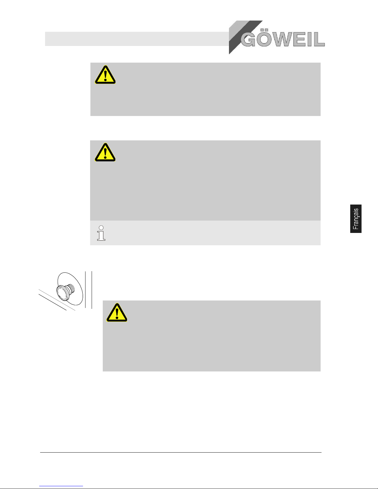
Affûteur MS 100
Sécurité
10.03.2009 9
Salissures et
objets épars
PRECAUTION !
Attention à ne pas trébucher sur les salissures et objets épars !
Les salissures et les objets épars peuvent faire trébucher et causer des lésions
substantielles.
Pour cette raison :
– maintenir toujours propre le poste de travail ;
– enlever les objets devenus inutiles.
2.6 Dispositifs de sécurité
AVERTISSEMENT !
Danger de mort suite au non fonctionnement de dispositifs de sécurité !
La sécurité n'est garantie que lors du fonctionnement irréprochable des dispositif de
sécurité.
Pour cette raison :
– Vérifier avant le début du travail si tous les dispositifs de sécurité sont correctement
installés et en parfait état de fonctionnement.
– Ne jamais mettre hors service les dispositifs de sécurité.
– Les éléments de sécurité ne doivent pas être shuntés ou modifiés.
– Veillez au bon fonctionnement et à la bonne accessibilité des dispositifs de sécurité tels
qu'interrupteurs d'arrêt d'urgence, cordons de déclenchement, etc.
INDICATION !
On trouvera toute information sur la position des dispositifs de sécurité dans le chapitre
« Structure et fonction ».
Les dispositifs de sécurité suivants sont installés :
Interrupteur d'arrêt d'urgence
Toute pression sur l'interrupteur d'arrêt d'urgence provoque un arrêt d'urgence de l'installation.
Lorsqu'un interrupteur d'arrêt d'urgence est actionné, il doit être déverrouillé par pouss
ée avant de pouvoir
procéder à la remise en marche.
AVERTISSEMENT !
Danger de mort par remise en marche intempestive de l'installation !
Toute remise en marche intempestive de l'installation peut entraîner de graves
dommages corporels qui peuvent être mortels !
Pour cette raison :
– avant toute remise en marche, s'assurer que l'origine de l'arrêt d'urgence a été
levée et que tous les dispositifs de sécurité sont montés et en bon état de
fonctionnement ;
– ne déverrouiller l'interrupteur d'arrêt d'urgence que lorsque aucun danger ne
subsiste.
Page 80
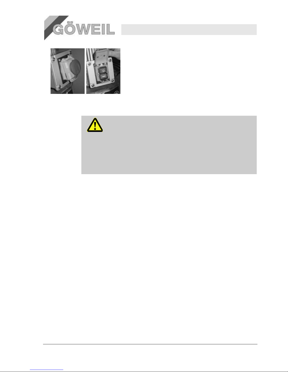
00
Affûteur MS 100
Sécurité
10 10.03.2009
Interrupteur de sécurité (arrêt d'urgence)
L'interrupteur de sécurité se situe à l'avant sur l'électromoteur.
2.7 Sécurisation contre toute remise en marche
DANGER !
Danger de mort par remise en marche intempestive par des personnes non
autorisées !
Lors de travaux dans la zone de risque, il est possible qu'une personne non autorisée
réenclenche par mégarde l'approvisionnement en énergie. Les personnes se trouvant dans
la zone de risque se trouvent alors en danger de mort.
Pour cette raison :
– observer scrupuleusement les indications sur la sécurisation contre un réenclenchement
intempestif figurant dans divers chapitres du manuel ;
– veiller toujours au processus de sécurisation contre un réenclenchement intempestif
décrit ci-dessous.
La machine est alimentée exclusivement par un câble secteur et une fiche (propre au pays).
Au choix avec 400 V ou 230 V electromoteur.
Sécurisation contre tout réenclenchement :
1. appuyer sur le bouton d'arrêt d'urgence afin qu'il s'enclenche
2. n'exécuter les autres travaux que dans ce mode
2.8 Attitude à adopter en cas de danger et d'accidents
Mesures
préventives
Rester vigilant ! Un accident ou un incendie est toujours possible !
Toujours garder à portée de main les instruments de premier secours (trousse médicale, couverture,
etc.) et extincteurs.
Familiariser le personnel avec les dispositifs de signalisation des accidents, de premiers secours et de
sauvetage.
Maintenir accessibles les voies d'accès pour les véhicules de secours.
Mesures en cas
d'accidents
Actionner immédiatement l'arrêt d'urgence.
Mettre en œuvre les mesures de premiers secours.
Evacuer les personnes de la zone de risque.
Informer les responsables sur le lieu de l'intervention.
Alarmer les secours.
Maintenir accessibles les voies d'accès pour les véhicules de secours.
Page 81
Affûteur MS 100
Sécurité
10.03.2009 11
2.9 Protection de l'environnement
PRECAUTION !
Risque pour l'environnement suite à une mauvaise manipulation de substances
nuisibles à l'environnement !
Toute fausse manœuvre avec des substances susceptibles de mettre en danger
l'environnement, et en particulier toute erreur dans l'élimination de telles substances, peut
provoquer de graves dommages à l'environnement.
Pour cette raison :
– respecter scrupuleusement les consignes suivantes :
– si des substances nocives portent atteinte à l'environnement, prendre immédiatement les
mesures qui s'imposent. En cas de doute, contacter l'autorité communale et l'informer du
sinistre.
Les substances suivantes sont susceptibles d'être nocives pour l'environnement :
Lubrifiants
Les lubrifiants, tels que graisses et huiles, contiennent des substances nocives. Elles ne doivent pas entrer en
contact avec notre environnement. Leur élimination doit être assurée par une entreprise spécialisée.
2.10 Signalisation
Les symboles et panneaux suivants se trouvent dans le périmètre de travail. Ils concernent directement la zone
dans laquelle ils sont apposés.
AVERTISSEMENT !
Risque de blessure dû à des symboles illisibles !
Avec le temps, les autocollants et les panneaux peuvent s'encrasser ou devenir illisibles
pour toute autre raison.
Pour cette raison :
– maintenir toujours lisibles les consignes de sécurité, les mises en garde et les conseils
d'utilisation ;
– remplacer immédiatement les panneaux ou autocollants endommagés.
2.11 Symboles d'avertissement
Tenir compte du manuel d'utilisation
N'utiliser l'objet désigné qu'après avoir lu son manuel d'instruction.
Risques d'écrasement
Avertissement de risques d'écrasement par ex. sur une machine ou des équipements (capots, habillages,
dispositifs de protection, clôtures, etc.).
Il faut avoir une vigilance accrue lors de travaux à ces postes de travail signalés.
Ne jamais mettre les mains dans la zone dangereuse tant que les pièces sont en mouvement.
2.12 Modifications
AVERTISSEMENT !
Risque de lésion suite à des modifications non autorisées !
Les modifications apportées à la machine sous forme d'ajouts et de transformations,
notamment celles qui pourraient altérer la sécurité, ne sont autorisées qu'avec l'accord écrit
du fabricant !
Page 82

00
Affûteur MS 100
Caractéristiques techniques
12 11.03.2009
3 Spécifications techniques
3.1 Informations générales
Indication Valeur Unité
Poids 69 kg
Longueur 930 mm
Largeur 675 mm
Hauteur 1455 mm
Modèle Sans unité d'affûtage linéaire
Indication Valeur Unité
Poids 73 kg
Longueur 1105 mm
Largeur 675 mm
Hauteur 1455 mm
Modèle Avec unité d'affûtage linéaire
INDICATION !
Les caractéristiques techniques (dimensions, poids, performances, etc.) se trouvent dans
les schémas joints (dessins) et dans les fiches techniques [→ Annexe].
3.2 Puissances connectées
Pos: 3.6 /KN2006-Projekte/NSD Lift AG/Te chnische Date n/002 1.1.0 Anschl usswerte --> NSD Comfort @ 45\mod_11 87710014840 _1.doc @ 566 242
Electrique
Indication (version 400 V) Valeur Unité
Tension 400/230 V
Puissance 1,1 kW
Fréquence 50 Hz
Vitesse 2835 t/min
Protection IP55
Electrique
Indication (version 230 V) Valeur Unité
Tension 230 V
Puissance 1,1 kW
Fréquence 50 Hz
Vitesse 2835 t/min
Protection IP55
Page 83
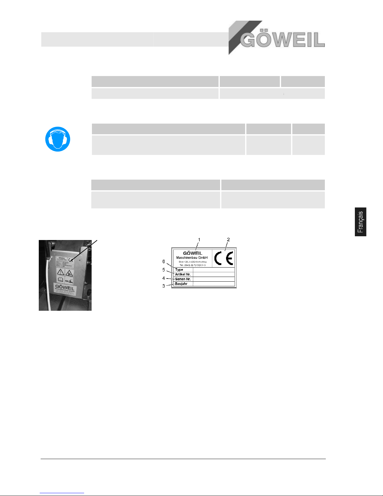
Affûteur MS 100
Caractéristiques techniques
10.03.2009
3.3 Conditions de service
Pos: 3.9 /KN2006-Projekte/NSD Lift AG/Tech nische Daten/003 1.1.0 Betriebsbe dingungen --> LSD Comfort @ 4 5\mod_11877 10247081_1.doc @ 566257
Dauer
Indication
Durée d'usinage maximale
3.4 Emissions
Pos: 3.12 /KN2006-Projekte/NSD Lift AG/Tec hnische Daten/00 5 1.1.0 Emissio nen --> LSD Comf ort @ 45\mod _1187711003739 _1.doc @ 566 337
Indication
Emission phonique (à vide / affûtage)
3.5 Consommables
Consommable
Lubrifiant
3.6 Plaque signalétique
La plaque signalétique
se trouve à l'arrière de
l'unité d'affûtage.
Valeur
Unité
conçu pour un usinage permanent
Valeur
75-80 / 102-
105
type
graisse multiusages à saponification à base de
lithium, classe NLGI 2
La plaque signalétique
comprend les indications
suivantes :
1 Fabricant
2
Label CE
3
Année de construction
4
Numéro de série
5
Numéro d'article
6 type
13
Unité
dB(A)
Page 84
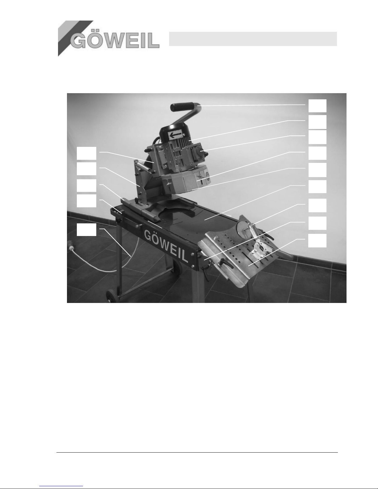
Affûteur MS 100
Structure et fonction
14 10.03.2009
4 Structure et fonction
Pos: 4.3 /KN2006-SM/Aufbau und Funktio n/002 1.1 Üb ersicht_Titel @ 9\mod_11440 46023684_1.doc @ 84432
4.1 Aperçu
Pos: 4.4 /KN2006-Projekte/NSD Lift AG/A ufbau und Fun ktion/1.1 Übersic ht --> NSD C omfort @ 45\mo d_11876975851 02_1.doc @ 5 66022
1 Poignée de commande
2 Electromoteur
3 Interrupteur Marche/Arrêt avec ARRET D'URGENCE
4 Tôle de protection (réglable)
5 Meule-boisseau
6 Etabli d'affûtage
7 Dispositif de serrage
8 Unité d'affûtage linéaire (option)
9 Tôle de réglage
10 Support du moteur
11 Tôle de retenue
12 Unité de rotation
13 Limiteur de rotation
14 Câble de connexion
4.2 Description brève
L'affûteur est destiné exclusivement à l'affûtage de couteaux concaves courbés, doté de
l'équipement en option « unité d'affûtage linéaire » également pour les couteaux droits des
presses et chargeuses agricoles.
Le couteau est posé sur la tôle de réglage et fixé avec le dispositif de serrage. Il faut ensuite
régler l'unité d'affûtage sur la tôle rotative de façon que le couteau puisse être affûté au rayon
correspondant. Une fois ceci achevé, on peut commencer à affûter le couteau.
2
3
4
5
6
7
8
9
10
Page 85
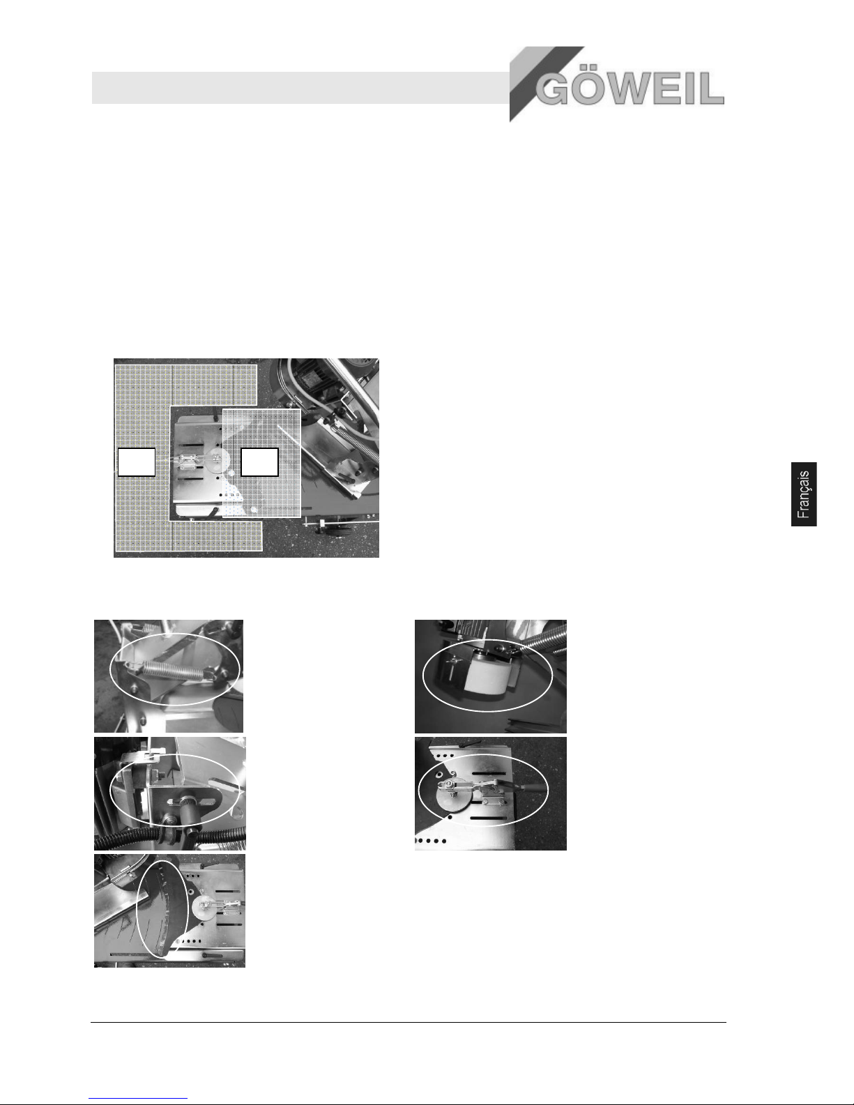
Affûteur MS 100
Structure et fonction
10.03.2009 15
4.3 Connexions
4.3.1 Connexions électriques
L'affûteur de couteau est livré sans fiche secteur. Le raccordement électrique se fait donc selon le pays
par un électricien. Il faut absolument veiller au sens de rotation du moteur ! Brancher la fiche selon le
plan des connexions joint !
4.4 Périmètres de travail et de danger
4.4.1 Périmètres de travail
1. Périmètre devant la machine
2. Zone d'affûtage
4.4.2 Périmètres de danger
1. Mécanisme à levier
pour lever et
abaisser le support
du moteur
2. Meuleboisseau
3. Mécanisme pour
régler l'angle
d'affûtage
4. Dispositif de
serrage des
couteaux
5. Point d'affûtage
Page 86
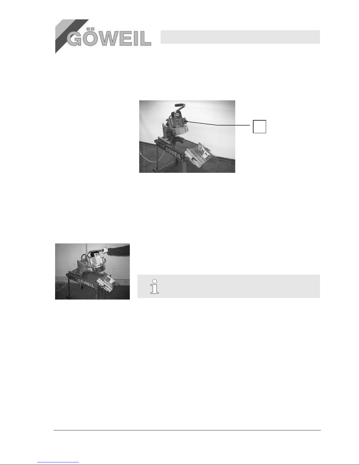
16
4.5
Emplacement du bouton d'arrêt d'urgence
4.5.1 Aperçu
La machine est équipée d'un bouton d'arrêt d'urgence. Lorsque le bouton est appuyé, la machine s'éteint
immédiatement.
4.6
Eléments de commande
La commande de la machine se fait à l'aide d'une poignée.
4.6.1
Poignée de commande
Les fonctions suivantes sont possibles avec la poignée de commande :
4.7
Modes de fonctionnement
Mode manuel (avec la poignée de commande)
Structure et fonction
1 Bouton d'arrêt d'urgence au moteur
abaissement et relèvement de l'unité d'affûtage
mouvement rotatif pour affûter les couteaux
INDICATION !
Explication sur la poignée de commande [→
chapitre
page 17 »].
1
Affûteur MS 100
10.03.2009
« 6. Commande –
Page 87

Affûteur MS 100
Transport, emballage
10.03.2009 17
5 Transport, emballage
5.1 Inspection après le transport
Vérifier la livraison dès son arrivée. Vérifier son intégralité et l'absence de dommages de transport.
Lors de dommages extérieurs de transport identifiables, procéder comme suit :
ne pas accepter la livraison ou émettre des réserves ;
noter l'étendue des dommages sur les documents de transport ou sur le bon de livraison du transporteur ;
introduire une réclamation.
INDICATION !
Réclamer chaque défaut constaté dès sa découverte. Les demandes à réparation du
dommage ne peuvent être présentées que durant les délais de réclamation en vigueur.
5.2 Emballage
Que faire des
matériaux
d'emballage?
Eliminer les emballages conformément aux dispositions légales et aux prescriptions locales en vigueur.
PRECAUTION !
Dommages à l'environnement dus à une élimination erronée
Les matériaux d'emballage sont de précieuses matières premières et peuvent dans de
nombreux cas être réutilisés ou être conditionnés en vue de leur recyclage.
Pour cette raison :
– éliminer les matériaux d'emballage de manière conforme à la protection de
l'environnement
– tenir compte des prescriptions locales en vigueur le cas échéant, confier leur élimination
à une entreprise spécialisée.
6 Utilisation
6.1 Sécurité
Equipement
personnel de
protection
Porter l'équipement de protection suivant lors de tous les travaux de manipulation :
Tenue de protection
Chaussures de sécurité
Lunettes de protection
Casque antibruit
Stabilité
AVERTISSEMENT !
Risque de lésion suite à un manque de stabilité !
Si la machine n'est pas suffisamment stable durant son fonctionnement, ceci peut provoquer
de graves lésions.
Pour cette raison :
– installer la machine sur un fond rigide, sec et plan et la sécuriser contre les
déplacements.
Page 88

Affûteur MS 100
Utilisation
18 10.03.2009
Distance de
sécurité
AVERTISSEMENT !
Risque de lésion suite à une distance de sécurité insuffisante !
Risque de graves lésions en cas de distance de sécurité insuffisante avec les périmètres de
danger de la machine.
Pour cette raison :
– respecter une distance de sécurité suffisante durant le fonctionnement de la machine.
Pos: 7.8 /KN2006-SM/Bedienung/003 1.1. 0 Grundlegendes @ 9\mod_ 1144402038705 _1.doc @ 8647 6
Manipulation
incorrecte
AVERTISSEMENT !
Risque de blessure suite à une manipulation incorrecte !
Toute utilisation incorrecte de l'installation peut entraîner des dommages corporels et
matériels importants.
Pour cette raison :
– la machine ne doit être commandée que par une seule personne.
– Exécuter toutes les opérations selon les indications du présent manuel.
– – Avant le début du travail, s'assurer que tous les capots et dispositifs de sécurité
sont installés et en bon état de fonctionnement.
– Ne jamais mettre hors service les dispositifs de sécurité durant le fonctionnement.
– veiller au bon ordre et à la propreté du lieu de travail ! Les éléments et outils épars ou
entassées sont des sources d'accidents. ;
6.2 Première mise en service
La machine est partiellement prémontée à la livraison.
1. Enlever l'emballage de la machine et la monter selon le plan « Montage MS100 » joint.
Couples de serrage pour M6 => 10Nm
Couples de serrage pour M8 => 25Nm
2. Contrôler si la meule-boisseau n'a pas subi de dommages.
3. Mettre en place la fiche secteur.
Il faut choisir la fiche secteur selon la version du moteur et le pays.
AVERTISSEMENT !
Risque de lésion suite à une installation électrique incorrecte !
Le raccordement doit être effectué par un électricien !
Il est vivement recommandé de protéger chaque branchement contre l'humidité et la saleté.
Page 89
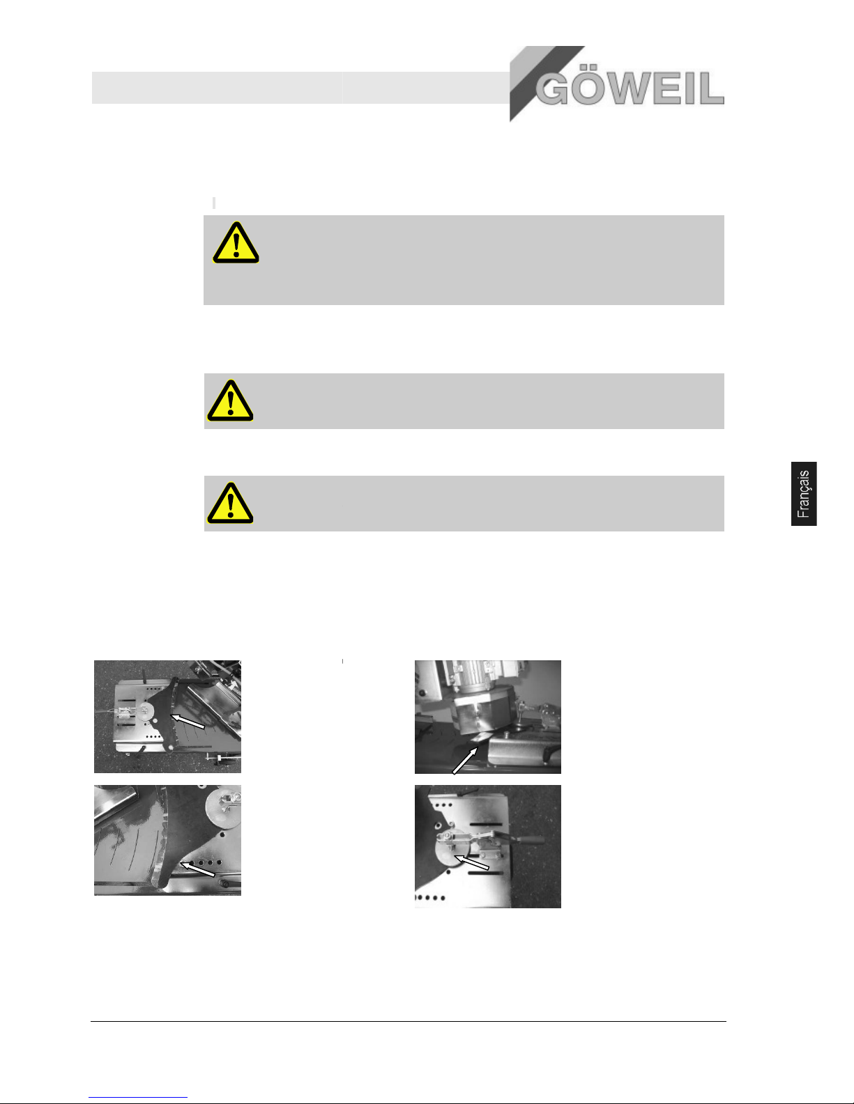
Affûteur MS 100
Utilisation
10.03.2009
6.3 Préparatifs
Pos: 7.9 /KN2006-SM/nL.......... Seitenumbruc h .......... @ 8\mod _11419983347 03_0.doc @ 754 89
6.3.1 Mise en service
1. I
nstaller la machine sur un sol plat et rigide.
AVERTISSEMENT !
Risque de lésion suite à une installation incorrecte !
Une installation incorrecte peut provoquer de graves lésions.
Pour cette raison :
–
s'assurer que l'on dispose de suffisamment de plac
2. Brancher la fiche secteur
Brancher la fiche secteur dans une prise de courant prévue à cet effet.
AVERTISSEMENT !
Risque de décharge électrique suite à une mauvaise manipulation des câbles !
3. Contrôler la meule-
boisseau
AVERTISSEMENT !
Contrôler la meule
6.4
Positionner le couteau courbé
Pos: 7.18 /KN2006-SM/Bedienung/007 1.1 Still setzen im Notfall -- > Anlage und grö ssere Masc hine @ 9\mod_11 44432835796 _1.doc @ 86788
En présence de situations dangereuses, arrêter le plus vite possible les mouvements de la machine et couper
l'alimentation en énergie.
Il faut en outre veiller que le couteau courbé soit bie
serrage et qu'il repose à bord des vis de butée.
1.
Le couteau courbé doit
reposer au bord au
centre de la tôle de
réglage. Face coupe
lisse en haut, lame
dentée en bas.
3.
Placer et fixer les vis de
butée le plus possible
vers l'extérieur.
e pour manipuler la machine.
-boisseau avant chaque mise en service !
n serré avec le dispositif de
2.
La surface de coupe doit
être en saillie d'env. 2
par rapport à la tôle de
réglage.
4.
Positionner le dispositif
de serrage de façon que
le porte
-
toute sécurité le couteau
à affûter (env. semi(
chevauchement).
19
cm
couteau serre en
-
Page 90
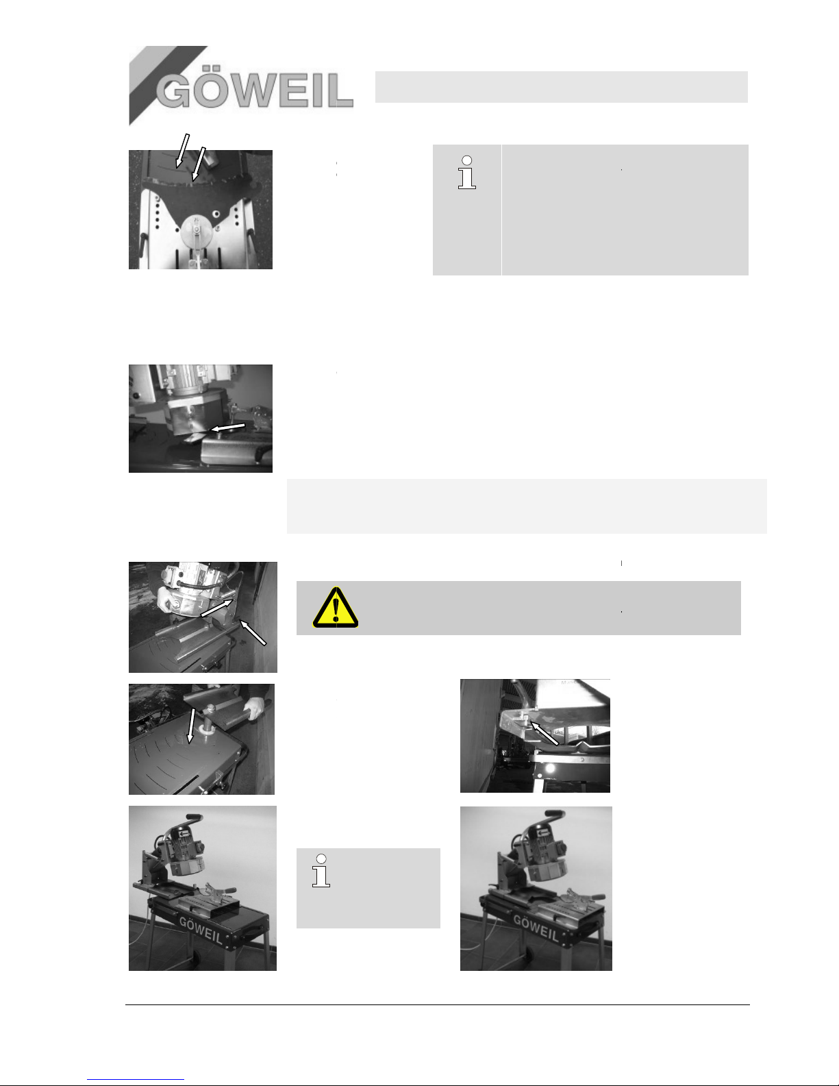
20
5.
Déplacer la tôle de
réglage jusqu'à ce que le
rayon du couteau
coïncide avec la
graduation de rayon et
fixer.
6.5
Régler l'unité d'affûtage
Pos: 7.18 /KN2006-SM/Bedienung/007 1.1 Still setzen im Notfall -- > Anlage und grö ssere Masc hine @ 9\mod_11 44432835796 _1.doc @ 86788
Régler l'unité d'affûtage de façon que la meule
photo suivante).
.
qu'il repose à bord des vis de butée.
L'écart entre la tôle de protection de la meule
possible.
Afin de pouvoir tout affûter, du plus petit au plus grand rayon, il est possible de tourner
l'unité de rotation de l'unité d'affûtage de 180°.
Pour cela, les opérations suivantes sont requises :
1.
desserrer le levi
2.
Soulever l'unité de
rotation, l'enlever de
glissière et tourner de
180°. Remettre en place
l'unité de rotation. Enfiler
de nouveau l'unité
d'affûtage par l'arrière sur
l'unité de rotation, la régler
et la fixer.
4.
Position de l'unité
d'affûtage pour les
rayons.
la
CONSEIL !
Il est recommandé de repérer le contour du dos
du couteau sur la tôle de réglage. Ceci facilite le
positionnement des couteaux su
-
boisseau soit exactement au c
Il faut en outre veiller que le couteau courbé soit bien serré avec le tendeur horizontal et
-
boisseau et le couteau courbé
er de serrage et retirer l'ensemble de l'unité d'affûtage en la tirant vers l'arrière.
ATTENTION !
Veiller lorsqu'on retire l'unité d'affûtage que celledes mains – RISQUE DE LESION !
la
petits
CONSEIL !
Pour la plupart
des couteaux,
l'unité de rotation
est à régler
comme illustré ici.
Affûteur MS 100
Utilisation
10.03.2009
ivants à affûter.
entre dans la prise (Cf.
doit être le moindre
ci ne s'échappe pas
3. Il faut veiller en
l'occurrence que les
plaquettes de serrage
soient bien insérées
sous l'unité d'affûtage.
5. Position de l'unité
d'affûtage pour les
grands rayons.
Page 91
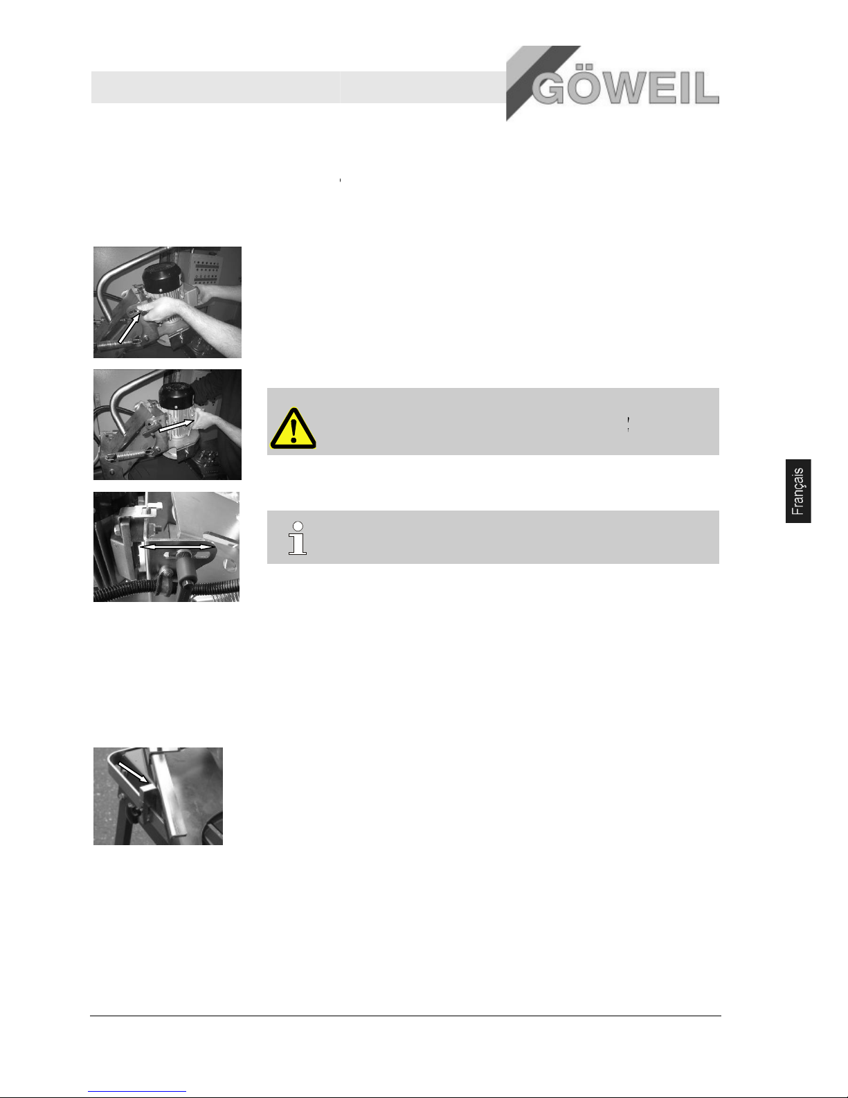
Affûteur MS 100
Utilisation
10.03.2009
6.6 Régler l'angle d'affûtage
Pos: 7.18 /KN2006-SM/Bedienung/007 1.1 Still setzen im Notfall -- > Anlage und grö ssere Masc hine @ 9\mod_11 44432835796 _1.doc @ 86788
Etant donné que pour les différents modèles de couteaux l'angle d'affûtage est différen
doit être réglable.
Les opérations suivantes sont requises :
.
Il faut en outre veiller que le couteau courbé soit bien serré avec le tendeur horizontal et
qu'il repose à bord des vis de butée.
1.
Desserrer le levier de serrage d'un côté.
2.
Tenir d'une main l'électromoteur et desserrer le second levier de serrage.
3.
Procéder au
CONSEIL !
L'angle d'affûtage correct se règle plus facilement avec un nouveau couteau.
6.7
Régler le limiteur de rotation
Pos: 7.18 /KN2006-SM/Bedienung/007 1.1 Still setzen im Notfall -- > Anlage und grö ssere Masc hine @ 9\mod_11 44432835796 _1.doc @ 86788
Le limiteur de rotation (butée) doit être réglée de façon que la meule
surface d'affûtage et n'affûte pas au début ou à la fin du couteau au
L'ajustement peut se faire au cas par cas.
1.
Desserrer la vis étoile
2.
Procéder au réglage
3.
Resserrer à fond la vis étoile.
ATTENTION !
En ouvrant le second levier de serrage, ne tenir l'électromoteur que par le
côté avant car il y a risque de lésion si on le tient par derrière !
réglage de l'angle d'affûtage et revisser à fond les deux leviers de serrage.
-
boisseau se situe dans la
-des
sus de l'arête.
.
21
t, celui-ci
Page 92
22
6.8 Fonctionnement
Equipement personnel
de protection
Porter l'équ
Tenue de protection
Chaussures de sécurité
Lunettes de protection
Casque antibruit
Information
ATTENTION
Avant de mettre en marche l'affûteur de couteaux, lire attentivement le
de fonctionnement pour se familiariser avec tous les éléments de la machine !
Couple de
démarrage
ATTENTION
Grand couple de démarrage de l'électromoteur. Par conséquent, tenir fermement la
poignée de commande lors de la mise en marc
Changement
de couteau
ATTENTION
Le changement de couteau ne doit être fait que lorsque la meule
totalement arrêtée.
Point
d'affûtage
ATTENTION
Après l'affûtage, ne toucher en aucun cas le point d'affûtage car celui
chaud et tranchant ! RISQUE ELEVE DE LESION !
6.8.1
6.8.1 Procédure de travail
La procédure suivante est requise pour affûter les couteaux :
.
qu'il repo
se à bord des vis de butée.
1.
Positionner le couteau courbé et serrer
couteau courbé
.
qu'il repose à
2.
Démarrer le moteur à l'aide de l'interrupteur vert (I) sur le bouton d'arrêt d'urgence tout en
tenant la poignée de commande
3.
Affûter le couteau courbé en faisant des déplacements réguliers droite
4.
Poursuivre l'affûtage jusqu'à ce que le couteau soi
5.
Arrêter l'électromoteur, attendre l'arrêt total de la meule
mettre en place le prochain couteau à affûter selon les indications à la
«
Positionner couteau courbé
ipement de protection suivant lors de tous les travaux de manipulation :
!
!
he.
!
!
Il faut en outre veiller que le couteau courbé soit bien serré avec le tendeur horizontal et
à fond. Cf. à ce propos page 19
».
Il faut en outre veiller que le couteau courbé soit bien serré avec le tendeur horizontal et
bord des vis de butée.
.
ATTENTION !
La pressio
n d'affûtage ne doit pas être trop élevée ! Si une pression trop
importante est exercée, les couteaux perdent leur dureté (coloration
bleutée au point d'affûtage).
Veiller aux projections d'étincelles !
t totalement affûté.
-
boisseau, retirer le couteau courbé et
».
Affûteur MS 100
Utilisation
10.03.2009
s instructions
-boisseau est
-ci est très
pt. 6.4 « Positionner
-gauche !
page 19 Pt. 6.4
Page 93
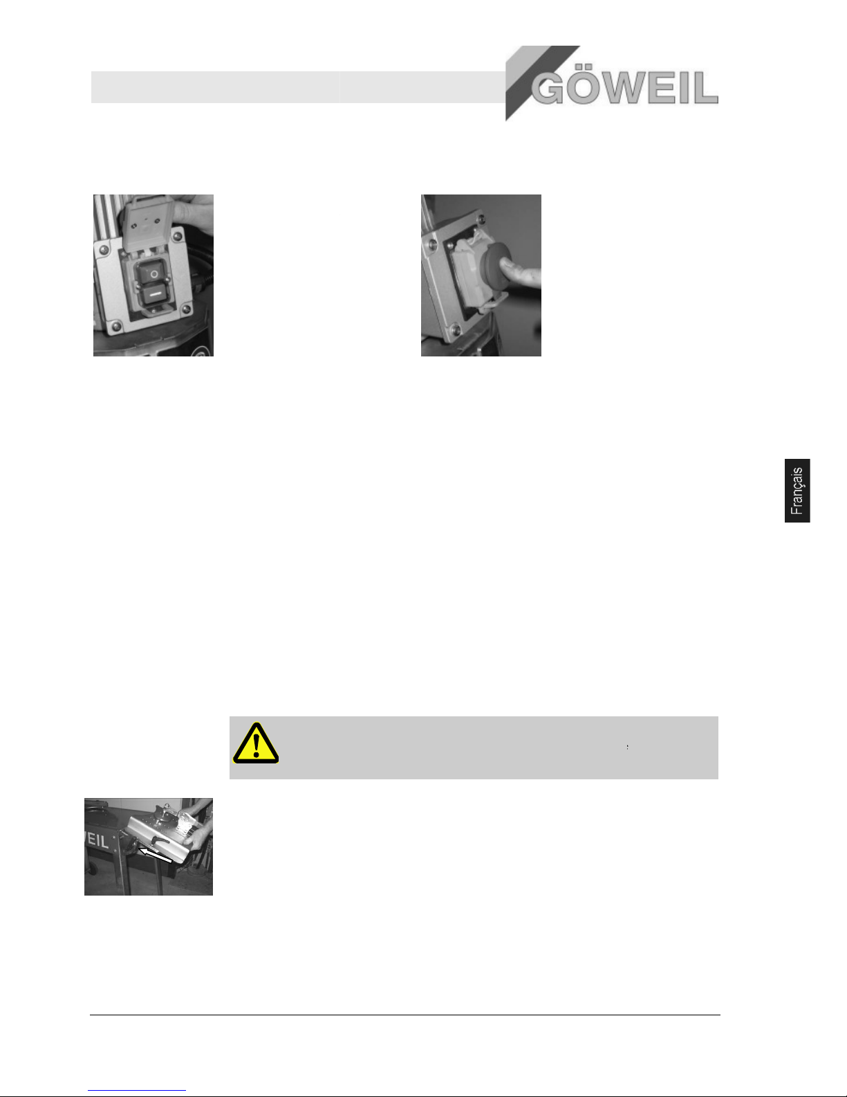
Affûteur MS 100
Utilisation
10.03.2009
6.9 Arrêter la machine
1.
Arrêter la machine avec
l'interrupteur d'arrêt (bouton
rouge « 0 »)
6.10 Unité d'a
ffûtage linéaire (option)
L'unité d'affûtage linéaire permet d'affûter des couteaux droits.
Pour affûter des couteaux droits, il suffit de monter la tôle de réglage de l'établi d'affûtage sur l'établi
d'angle
de l'unité d'affûtage linéaire.
6.10.1
Montage de l'unité d'affûtage linéaire
Voir plan «
Montage de l'unité d'affûtage linéaire
Couples de serrage pour M6 => 10Nm
Couples de serrage pour M8 => 25Nm
6.10.2
Réglage de l'unité d'affûtage linéaire
Procéder a
ux réglages comme décrit
limiteur de rotation ».
IMPORTANT !
Il faut veiller lors de l'affûtage de couteaux droits que la surface à affûter soit à
l'horizontale. Autrement dit, la meule
.
Il faut en outre veiller que le couteau courbé soit bien serré avec le tendeur horizontal et qu'il
repose à bord des vis de butée.
1.
Orienter l'unité d'affûtage linéaire selon l'angle d'affûtage. Les deux éc
pourvues de quatre cavités.
La cavité supérieure correspond à 0 degré (horizontalement) de l'établi d'angle. Les autres
échelonnements se font en 15 degrés.
Desserrer les vis à fermeture rapide
2.
Appuyer sur le cache
verrouillable de l'interrupteur
d'arrêt d'urgence jusqu'à
fermeture complète.
3.
Retirer la fiche secteur
».
.
.
à la page 19 Pt. 6.3 « Préparatifs » à page 21
Pt. 6.7
-
boisseau doit aussi être à l'horizontale !
lisses d'angle sont chacune
- régler l'angle - resserrer à f
ond les vis à fermeture rapide.
23
« Régler le
Page 94
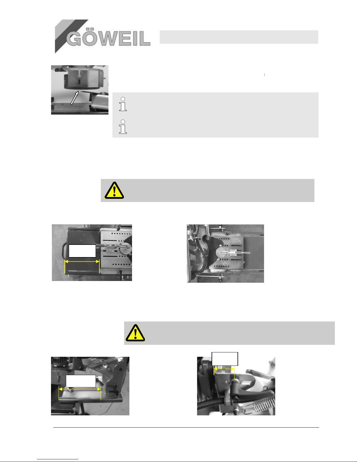
24
.
Il faut en outre veiller que le couteau courbé soit bien serré avec le tendeur horizontal et qu'il
repose à bord des vis de butée.
2. La meule-
boisseau et la surface d'affûtage doivent être à plat (0 degré) (
l'angle d'affûtage
3.
La procédure de travail est la même que celle décrite
travail ».
6.11
Positionner les couteaux pour la presse à balles rondes Krone VP 1500 et VP
1800
Les prescriptions de réglage spéciales pour les couteaux
sont indiquées ci-
dessous !
IMPORTANT !
Les valeurs suivantes ne sont qu'indicatives car elles peuvent légèrement variées
selon l'usure des couteaux !
6.11.1
Réglage de la tôle de réglage, position du cout
La cote indiquée n'est qu'indicative !
6.11.2
Régler l'unité d'affûtage
6.11.2.1
Ecart de la tôle de retenue, réglage de l'angle d'affûtage
La cote indiquée n'est qu'indicative !
275 mm
270mm
page 21
»)
à la page 22
Pt. 6.8.1
INDICATION !
Si l'unité d'affûtage linéaire n'est plus nécessaire, elle peut être escamotée.
CONSEIL !
L'angle d'
affûtage correct se règle plus facilement avec un nouveau couteau.
Krone des presses à balles rondes VP 1500, 1800
eau à la tôle de réglage
Position correcte du couteau !
IMPORTANT !
L'un
ité de rotation de l'unité d'affûtage doit être tournée de 180° ! Cf. page 22 pt. 6.5
« Régler l'unité d'affûtage ».
40mm
Affûteur MS 100
Utilisation
10.03.2009
Pt. 6.6 « Régler
« Procédure de
Page 95

00
Affûteur MS 100
Pannes et anomalies
19.02.2009 25
7 Pannes et anomalies
On trouvera dans le chapitre suivants les causes possibles d'anomalies et les travaux permettant d'y remédier.
En cas d'anomalies répétées, raccourcir les intervalles de maintenance en fonction de la sollicitation effective
de la machine.
Dans le cas d'anomalies ne pouvant être éliminées en se basant sur les indications suivantes, contacter le
concessionnaire le plus proche ou le fabricant.
7.1 Sécurité
Personnel
Les travaux de dépannage décrits ici, peuvent, sauf stipulation contraire, être effectués par
l'utilisateur.
Certains travaux doivent être exécutés par un personnel qualifié spécialement formé ou par le
fabricant lui-même. Ces travaux sont désignés en tant que tels dans la description des diverses
pannes et anomalies.
Les travaux sur les installations électriques ne doivent être exécutés que par des électriciens
qualifiés.
Equipement
personnel de
protection
Porter l'équipement de protection suivant durant tous les travaux de dépannage :
Tenue de protection
Chaussures de sécurité
Sécurisation
contre toute
remise en
marche
DANGER !
Danger de mort par remise en marche intempestive par des personnes non
autorisées !
Lors de travaux de dépannage, il y a risque qu'une personne non autorisée réenclenche
par mégarde l'alimentation en énergie. Les personnes se trouvant dans la zone de
risque se trouvent alors en danger de mort.
Pour cette raison :
– Avant le travail sur des installations électriques, couper l'alimentation et la
sécuriser contre toute remise en marche intempestive.
– Retirer la fiche secteur
Dépannage
non conforme
AVERTISSEMENT !
Risque de blessure lors de l'élimination incorrecte des pannes !
Toute élimination incorrecte des pannes peut entraîner des dommages corporels et
matériels importants.
Pour cette raison :
– avant le début des travaux veiller à disposer d'un espace de montage suffisant ;
– veiller au bon ordre et à la propreté du lieu de travail ! Les éléments et outils épars
ou entassées sont des sources d'accidents. ;
– lorsque des éléments ont été retirés, veiller au montage correct, remonter tous les
éléments de fixation et veiller aux couples de serrage des vis ;
– monter tous les capots et dispositifs de sécurité conformément et contrôler leur
fonctionnement.
Page 96

Affûteur MS 100
Pannes et anomalies
26 10.03.2009
Attitude à
adopter en cas
de pannes
Par principe :
1. Lors de pannes représentant un danger direct pour les personnes ou les biens matériels, actionner
immédiatement la fonction d'arrêt d'urgence.
2. Déterminer l'origine de la panne.
3. Lorsque le dépannage demande un travail dans une zone de risque, mettre l'installation hors circuit et
sécuriser contre toute remise en marche intempestive.
4. Informer immédiatement les responsables se trouvant sur le site de la panne.
5. Suivant la nature de la panne, la faire éliminer par un personnel qualifié ou le faire soi-même.
INDICATION !
Le tableau des pannes présenté ci-dessous vous indique qui est autorisé à y remédier.
7.2 Table des pannes
7.2.1 Pannes générales
Panne Cause possible Remède Dépannage par
Electromoteur ne
fonctionne pas
Absence d'alimentation
électrique
Brancher le câble d'alimentation de la
machine
Opérateur
Fusible défectueux Remplacer le fusible dans l'armoire
électrique
Electricien
Câble de connexion
endommagé
Remplacer le câble de connexion Electricien
Electromoteur s'arrête
rapidement
Protection thermique
inactive / active
Contrôler la fiche
Est-ce que l'électromoteur est correctement
raccordé selon le plan des connexions ?
Electricien
Meule-boisseau vibre Balourd, rupture d'éléments remplacer Opérateur
7.3 Élimination des dérangements
7.3.1 Changement de la meule-boisseau
IMPORTANT !
La meule-boisseau doit être utilisée selon les indications du fabricant !
La meule-boisseau ne doit être remplacée que par le personnel qualifié et
instruit !
La meule-boisseau doit être utilisée au maximum à l'extrémité de la zone
de réglage de la tôle de protection réglable !
Page 97
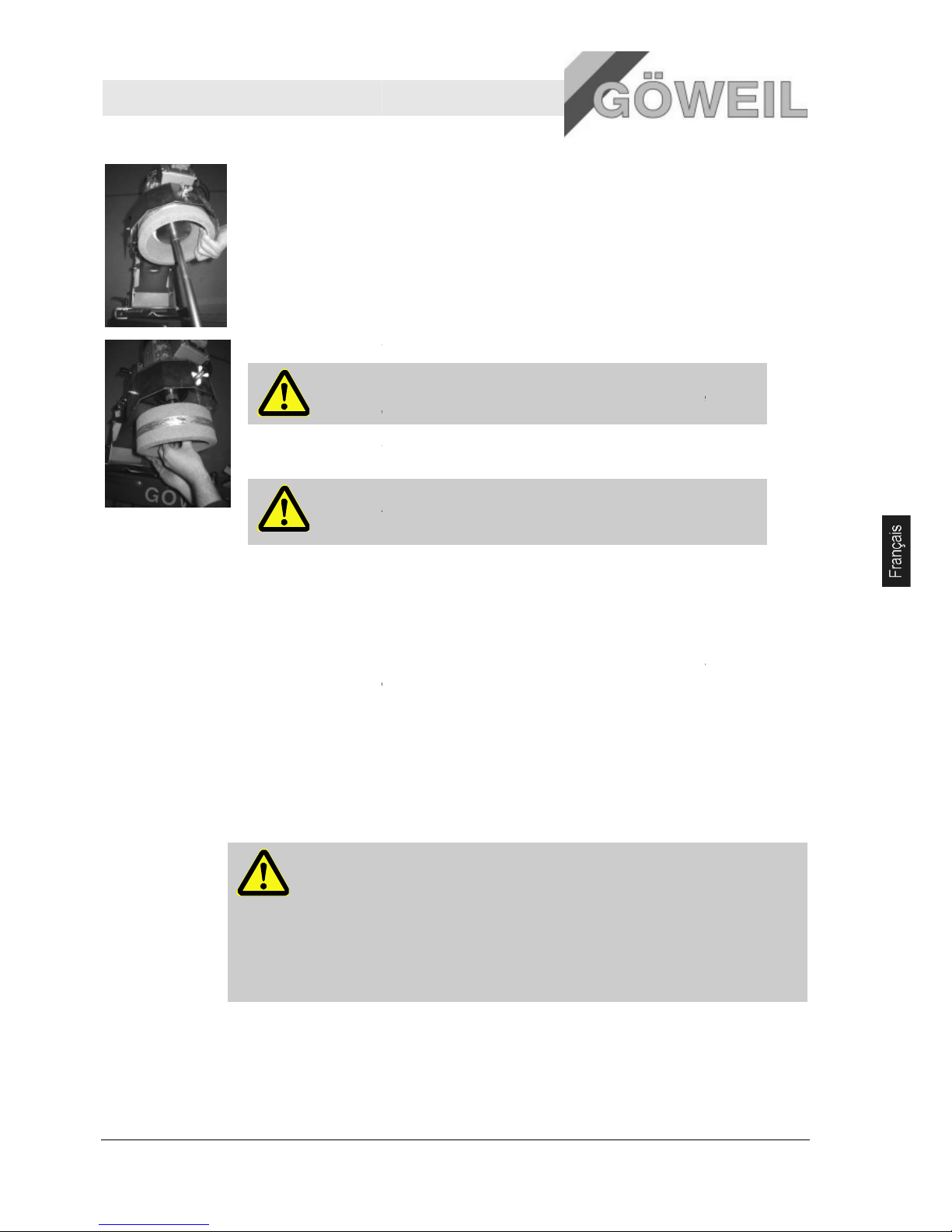
Affûteur MS 100
Entretien
10.03.2009
.
Il faut en outre veiller que le co
repose à bord des vis de butée.
1. Dévisser la meule-
boisseau par le dessous avec un outil adéquat et maintenir à la main.
.
Il faut en outre veiller que le couteau courbé soit bien serré
repose à bord des vis de butée.
2. Retirer la meule-
boisseau avec le disque se serrage de l'axe du moteur.
IMPORTANT !
Repérer la meule
élimination !
3. Enfiler la nouvelle
meule
Couples de serrage pour M8 => 25Nm
DANGER !
Eviter tout choc sur la nouvelle meule
RISQUE d'éclatement !
8 Entretien
Pos: 9.3 /KN2006-SM/Wartung/002 1 Sicherh eit_Titel @ 9\mo d_114443483 1619_1.doc @ 8681 0
8.1 Sécurité
Pos: 9.4 /KN2006-SM/Wartung/003 1.1.0 Personal --> Standard --
> ggf. anpassen @ 9
Personnel
Les travaux de maintenance décrits
Certains travaux de maintenance doivent être exécutés par un personnel qualifié spécialement formé ou par
le fabricant lui-
même. Ces travaux sont signalés en tant que tels dans la
maintenance.
Les travaux sur les installations électriques ne doivent être exécutés que par des électriciens qualifiés.
Equipement
personnel de
protection
Porter l'équipeme
nt de protection suivant durant tous les travaux de maintenance :
Tenue de protection
Chaussures de sécurité
Sécurisation
contre toute
remise en
marche
DANGER !
Danger de mort par remise en marche intempestive par des personnes non
autorisé
es !
Lors de travaux de maintenance dans la zone de risque, il est possible qu'une personne
non autorisée réenclenche par mégarde l'alimentation en énergie. Les personnes se
trouvant dans la zone de risque se trouvent alors en danger de mort.
Pour cette ra
–
avant le travail sur des installations électriques, couper l'alimentation et la sécuriser
contre toute remise en marche intempestive.
uteau courbé soit bien serré avec le tendeur horizontal et qu'il
avec le tendeur horizontal et qu'il
-
boisseau usagée comme telle et procéder à son
-
boisseau ainsi que le disque de serrage sur l'axe du moteur et visser à fond.
.
-boisseau !
\mod_1144434832402_1.doc @ 86817
ici, peuvent, sauf stipulation contraire, être effectués par l'opérateur.
description des divers travaux de
ison :
27
Page 98

Affûteur MS 100
Entretien
28 10.03.2009
Tension des
ressorts
PRECAUTION !
Risque de lésion par retour trop rapide !
Les leviers sous tension de ressort peuvent provoquer des lésions.
Pour cette raison :
– lors de travaux sur des leviers sous tension des ressorts, procéder avec précaution ;
– respecter une distance de sécurité suffisante.
Protection de
l'environnement
Pour protéger l'environnement, veiller aux consignes suivantes lors des travaux de maintenance :
Enlever toute la graisse usagée ou en excédent des points de lubrification et dépolluer conformément aux
dispositions locales en vigueur.
8.2 Planning de maintenance
Les travaux de maintenance, requis pour le bon fonctionnement de la machine, sont décrits ci-dessous.
Si lors des contrôles réguliers une usure accrue est constatée, il faut alors réduire les intervalles de
maintenance en fonction des signes d'usure effectifs
Pour toutes questions relatives aux travaux et aux intervalles de maintenance, contacter le fabricant ou un
concessionnaire.
Intervalle
(HS - heures
de service)
Travail de maintenance Exécuté par
Généralités
Avant chaque
utilisation
Enlever les corps étrangers et les saletés Opérateur
Mobilité des éléments Opérateur
Etat de la meule-boisseau Opérateur
Usure de la meule-boisseau Opérateur
annuel Graisser le palier de guidage de l'unité de rotation Opérateur
Page 99
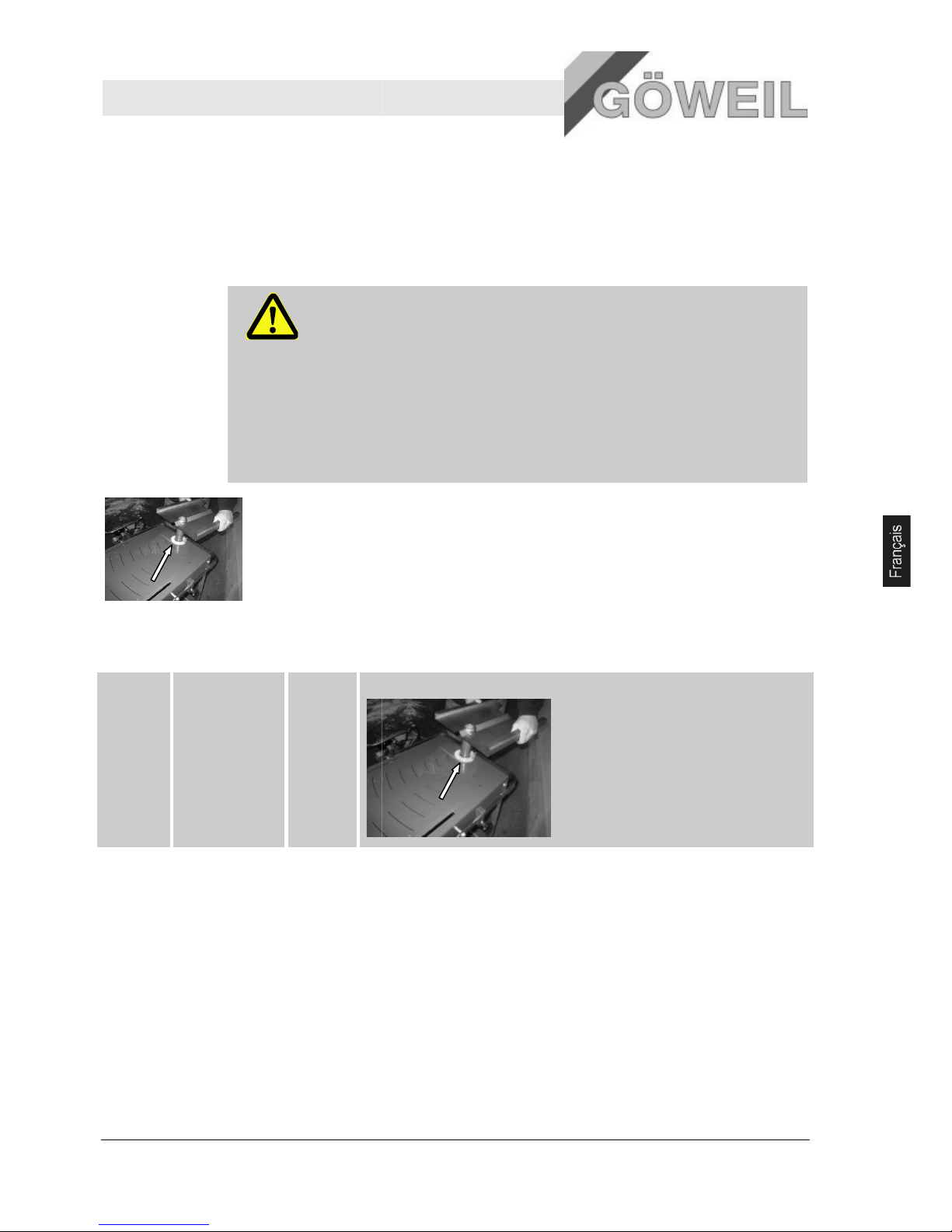
Affûteur MS 100
Entretien
10.03.2009
8.3 Travaux de maintenance
8.3.1 Graisser les rotules
Equipement de protection requis en sus :
Gants de protection
Lubrifiants
AVERTISSEMENT !
Risque d'incendie et d'intoxication ainsi que sur la santé dû aux lubrifiants !
Au contact de sources c
Le contact avec de l'huile et de la graisse peut porter atteinte à la santé.
Pour cette raison :
–
pas de feu ouvert lors de travaux sur la machine ;
–
interdit de fumer ;
–
ne pas inhaler les vapeurs de graisse ;
–
éviter tout contact de la peau avec de l'huile et de la graisse ;
–
enlever immédiatement l'huile ou la graisse de la peau.
Sur l'affûteur, seul le palier de guidage de l'unité de rotation est à graisser avec graisse multiusage
usuelle.
8.4 Intervalles de graissage
annuel Palier de guidage
de l'unité de
rotation
1 Palier
Nettoyer auparavant le palier de guidage !
8.5 Mesures après maintenance
Pos: 9.33 /KN2006-SM/Wartung/009 1.1.0 Mass nahmen nach erfolgter Wartung - -> Standard @ 9\mod_114443 8981309_1.doc @ 86935
Exécuter les opérations suivantes avant de remettre en marche après les travaux de maintenance :
1.
vérifier le bon serrage de tous les vissages desserrés auparavant ;
2.
vérifier si tous les dispositifs de protection et les capots ont
3.
s'assurer que tous les outils, matériaux et autres équipements utilisés ont été retirés du périmètre de
travail ;
4.
nettoyer le périmètre de travail et enlever les substances éventuellement répandus, par ex. liquides
ou similaires ;
5.
s'assurer que tous les dispositifs de sécurité de la machine fonctionnent parfaitement.
haudes les lubrifiants peuvent s'enflammer.
été correctement remis en place ;
29
Page 100

Affûteur MS 100
Démontage
30 10.03.2009
9 Démontage
Pos: 10.3 /KN2006-SM/Demontage/001 1. 0 Nachdem das G ebrauchsend e erreicht ist. ..(Anlage) @ 9\m od_11445018 94460_1.doc @ 87460
A la fin de sa durée de vie, la machine doit être démontée et éliminée conformément dans le respect de
l'environnement.
Pos: 10.4 /KN2006-SM/nL---------- Abschnittsende ---------- @ 8\mod_1141997892953_0.doc @ 75471
INDICATION !
Le démontage est du ressort exclusif d'un personnel qualifié.
AVERTISSEMENT !
Danger suite à un démontage incorrect !
Le démontage requiert un personnel spécialisé et formé disposant d'une expérience
suffisante. Les erreurs commises lors du démontage peuvent provoquer des dommages
corporels et matériels particulièrement graves.
Pour cette raison :
– ne faire exécuter le démontage que par des collaborateurs du fabricant ;
– ne pas procéder soi-même au démontage.
9.1 Elimination
Si aucun accord de reprise ou d'élimination n'a été conclu, les éléments démontés doivent être recyclés :
métaux au rebut ;
plastiques au recyclage ;
trier les autres composants en fonction de leur nature avant de les éliminer.
PRECAUTION !
Dommages à l'environnement dus à une élimination incorrecte !
Les composants électriques et électroniques, les lubrifiants et les autres consommables doivent
être traités comme des déchets spéciaux et ne doivent être éliminés que par des entreprises
spécialisées agréées !
Pour toute information sur la dépollution, s'adresser aux autorités communales ou aux entreprises spécialisées.
Pos: 11.1 /KN2006-Projekte/Rüfenacht/Ers atzteilliste/1 Ersa tzteile - Titel @ 47\mod_ 1190042012578 _1.doc @ 623734
 Loading...