

Governors America EDG5500 User Manual

EDG5500
Electronic Digital Governor
With Quikset Display
INTRODUCTION
1
GAC’s EDG5500 digital governor is designed to regulate engine speed on diesel
and gaseous-fueled engines. The EDG system is a suitable replacement for any
mechanical governor system that needs flexibility, precision, or accurate control
of governed speed. The EDG is designed for industrial engine applications from
generator sets, and mechanical drives, to pumps or compressors.
Computer
With the use of GAC’s Quikset Display, the EDG5500 requires no computer or
internet connection.
SPECIFICATIONS
2
PERFORMANCE
Isochronous Operation ± 0.25%
Speed Range / Governor
Idle Adjust Full Range
Droop Range 1 - 5% regulation
Speed Trim Programmable 0-100%, (default = 5%)
Supply 12-24 VDC Battery Systems (7.0 to 33 VDC)
Polarity Negative Ground
Power Consumption 70mA max. continuous plus actuator current
Speed Sensor Signal 1.0-120 VRMS
Actuator 8-10 Amps Continuous
Load Share/Synchronizer
Input
Reverse Power Protection Ye s
Transient Voltage Protection 60V
Ambient Temperature -40° to 85°C (-40 to 180°F)
Relative Humidity up to 95%
All Surface Finishes Fungus Proof and Corrosion Resistant
CE Rated EN55011, EN50081-2, EN50082-2
Dimension See Section 3 “Installation”
Weight 1.8 lbs. (820 grams)
Mounting Any position, Vertical Preferred
Vibration 7G, 20-100 Hz
Shock 20G Peak
Testing 100% Functional Testing
COMPLIANCE / STANDARDS
Agency CE and RoHS Requirements
Communications SAE J1939 (Option)
(200-5000 RPM w/120 tooth flywheel) cont.
INPUT / OUTPUT
0-10 VDC ( 5V nominal, reversed, 100Hz / V )
ENVIRONMENTAL
PHYSICAL
RELIABILITY
Internet Connection
400Hz - 10 KHz
INSTALLATION
3
Vertical orientation allows for
the draining of fluids in moist
environments.
Mount in a cabinet, engine
enclosure, or sealed metal box.
Avoid Extreme Heat
[151]
5.94
[7]
4X
0.27
[144]
5.67
[127]
5.00
WIRING
4
* Keep reading for diagrams and/or additional notes
TERM. DEFINITION GAUGE NOTES
A
B
C Magnetic Pickup (+) #20 AWG
D Mag Pickup Ground #20 AWG
E Battery (-) #16 AWG
F Battery (+) #16 AWG
G Ground Signal #16 AWG * Variable speed/trim input & switches
H Not Used
J Variable Speed Input #20 AWG * 5K Ω Resistive Potentiometer
K Droop Select #16 AWG * Active when connected to Term. G
L Idle Select #16 AWG * Active when connected to Term. G
M Aux Input #20 AWG
N CAN L #20 AWG
P CAN H #20 AWG
1. Shielded cable should be used for all external connections to the EDG
control. One end of each shield, including the speed sensor shield, should
be grounded to a single point on the EDG case.
Actuator (+) #16 AWG
Actuator (-) #16 AWG
RECOMMENDATIONS
[127]
5.00
Dimensions:
Not polarity dependent
* Twist wires 14 turns per foot
A 15 amp fuse must be installed in the
positive battery lead to protect against
any overload or short circuit
* Load sharing / synchronizing, 5V
nominal (0-10V), reverse ramp
* Twist Wires 14 turns per foot.
[mm]
in
1
EDG5500 Electronic Digital Governor 6.15 PIB 4145 G
© 2015 Copyright All Rights Reserved
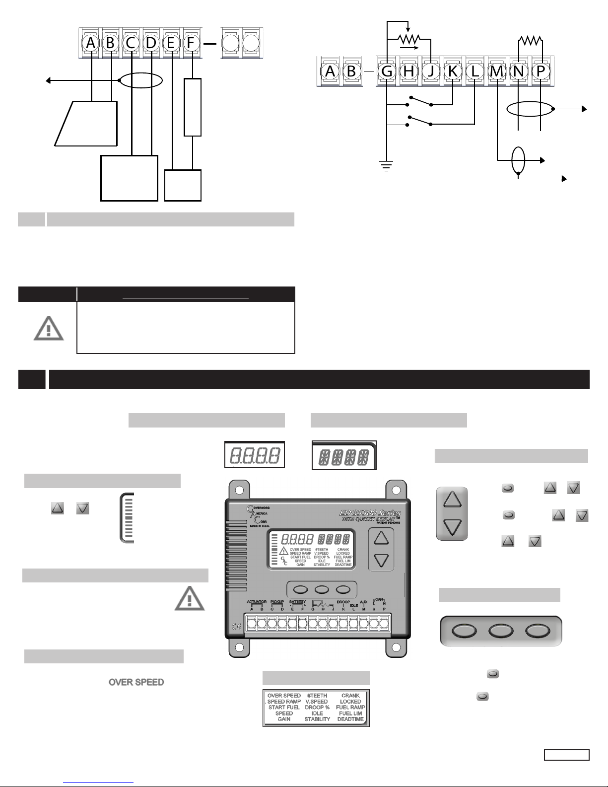
A DCB E F
CAN
( Optional )
Accessory
Input
DROOP
IDLE
Variable Speed /
Trim
120 Ohms
( End of CAN bus)
Ground to
Case
Ground to
Case
N P
Ground to Case
Fuse 15A Max
Actuator
Magnetic
Speed
Pickup
- +
Battery
(12V or 24V)
PIN 3 Magnetic Speed Pickup
• Wires must be twisted and/or shielded for their entire length
(14 turns per foot)
• Gap between speed sensor and gear teeth should not be smaller
than 0.02 in. (.51mm)
• Speed sensor voltage should be at least 1VAC RMS during crank
WARNING Loss of Magnetic Pickup Sensing
If the EDG5500 detects no input from the magnetic pickup,
the EDG will set the actuator to 0V and set the speed to 0
RPM. After the EDG has detected loss of magnetic pickup,
the display will flash the RPM along with the Warning Indicator. Parameters will be unchangeable.
DISPLAY & CONTROLS
5
Numerical Area
Displays the value of a selected parameter or live
running parameter
Throttle, Delta Speed Graph, & Current
Toggle between the 3 views:
Tap or
Loss of Magnetic Speed Pickup / Overcurrent
After the EDG has detected loss of magnetic
pickup, the display will flash the RPM along
with the Warning Indicator. Parameters will be
unchangeable.
Over Speed
“Over Speed” will blink when the unit is in overspeed.
(Cycle power to restart)
Quikset Menu
One row of parameters is displayed at
a time.
Alpha-Numerical Area
Displays the units for the parameter (e.g. RPM)
2
EDG5500 Electronic Digital Governor 6.15 PIB 4145 G
Parameter Adjust
Parameter
Adjust Up
Increment a Parameter Value:
HOLD and TAP or
Rapidly Increment a Value:
HOLD and HOLD or
Locking the Displpay
HOLD and for 2 seconds
Parameter
Adjust
Down
Column Select Buttons
21
To change the displayed row of parameters:
Tap any
To view a parameter value in a selected row:
Hold
For: SPEED
For: IDLE
For: FUEL LIM
3
Hold: Button 1
Hold: Button 2
Hold: Button 3
© 2015 Copyright All Rights Reserved
 Loading...