

Page 1
External Positioner (Fixed) Camera
Quick Installation Guide
Sales@GovComm.us | 305-937-2000 | 3830 SW 30 Avenue, Ft. Lauderdale, Florida 33312
GC-IL-Series
© GovComm, Inc. 2018
Page 2

External Postioner (Fixed) Camera - Quick Start Guide
3830 SW 30 Avenue, Ft. Lauderdale, Florida 33312 | 305-937-2000 | www.GovComm.us | Sales@GovComm.us
© GovComm, Inc. 2018
Thank you for purchasing GovComm’s network ITS Camera product. If there are any technical or
general questions, concerns or requests, please contact us through our website www.GovComm.us, by
email Sales@ GovComm.us or by telephone 1+305-937-2000.
This manual may contain several technical or printing errors, and the content is subject to change
without notice. We regularly improve and update our products and procedures described in the manual.
Updates will be added to new versions of this manual and posted onto the GovComm website.
DISCLAIMER STATEMENT
2
“Underwriters Laboratories, Inc. (“UL”) has not tested the performance or reliability of the
security or signaling aspects of this product. UL has only tested for re, shock or casualty
hazards as outlined in UL’s Standard(s) for Safety, UL60950-1. UL Certication does not cover
the performance or reliability of the security or signaling aspects of this product. UL MAKES NO
REPRESENTATIONS, WARRANTIES OR CERTIFICATIONS WHATSOEVER REGARDING
THE PERFORMANCE OR RELIABILITY OF ANY SECURITY OR SIGNALING RELATED
FUNCTIONS OF THIS PRODUCT.”
Safety Instruction
These instructions are intended to ensure that user can use the product correctly to avoid danger or
property loss.
The precaution measure is divided into “Warnings” and “Cautions”
Warnings: Serious injury or death may occur if any of the warnings are neglected.
Cautions: Injury or equipment damage may occur if any of the cautions are neglected.
Warnings Follow these safeguards to prevent
serious injury or death.
Cautions Follow these precautions to prevent
potential injury or material damage.
Warnings
• Proper conguration of all passwords and other security settings is the responsibility of the installer
and/or end-user.
• In the use of the product, you must be in strict compliance with the electrical safety regulations of the
region and nation. Please refer to technical specications for detailed information.
• Input voltage should meet both the SELV (Safety Extra Low Voltage) and the Limited Power Source
with 24 VAC or 12 VDC according to the IEC60950-1 standard. Please refer to technical specications
for detailed information.
• Do not connect several devices to one power adapter as adapter overload may cause over-heating
or a re hazard.
Page 3
External Postioner (Fixed) Camera - Quick Start Guide
3830 SW 30 Avenue, Ft. Lauderdale, Florida 33312 | 305-937-2000 | www.GovComm.us | Sales@GovComm.us
© GovComm, Inc. 2018
• Please make sure that the plug is rmly connected to the power socket. When the product is mounted
on wall or ceiling, the device should be rmly xed.
• If smoke, odor or noise rises from the device, turn off the power at once and unplug the power cable,
and contact the service center.
3
Cautions
• Make sure the power supply voltage is correct before using the camera.
• Do not drop the camera or subject it to physical shock.
• Do not touch sensor modules with ngers. If cleaning is necessary, use clean cloth with a bit of
ethanol and wipe it gently. If the camera will not be used for an extended period, please replace the
lens cap to protect the sensor from dirt.
• Do not aim the camera at the sun or extra bright places. Blooming or smearing may occur otherwise
(which is not a malfunction), and affect the endurance of sensor at the same time.
• The sensor may be burned out by a laser beam, so when any laser equipment is used, make sure
that the surface of sensor will not be exposed to the laser beam.
• Do not place the camera in extremely hot, cold (the operating temperature shall be -40°F – 175°F,
dusty or damp locations, and do not expose it to high electromagnetic radiation.
• To avoid heat accumulation, good ventilation is required for operating environment.
• Keep the camera away from liquid while in use.
• While in delivery, the camera shall be packed in its original packing, or packing of the same texture.
• If the product does not work properly, please contact us. Never attempt to disassemble the camera
yourself. (We shall not assume any responsibility for problems caused by unauthorized repair or
maintenance.)
Page 4

Table of Contents
1 Appearance Description . . . . . . . . . . . . . . . . . . . . . . . . . . . . . . . . . . . . . . . . . . . . . . . . . . . 5
1.1 Overview . . . . . . . . . . . . . . . . . . . . . . . . . . . . . . . . . . . . . . . . . . . . . . . . . . . . . . . . . . . . . . . . . 5
1.2 Micro SD Card Installation. . . . . . . . . . . . . . . . . . . . . . . . . . . . . . . . . . . . . . . . . . . . . . . . . . . 6
1.3 Initializing the Memory Card . . . . . . . . . . . . . . . . . . . . . . . . . . . . . . . . . . . . . . . . . . . . . . . . . 6
2 Installation . . . . . . . . . . . . . . . . . . . . . . . . . . . . . . . . . . . . . . . . . . . . . . . . . . . . . . . . . . . . . . . . . 7
2.1 Ceiling Mounting . . . . . . . . . . . . . . . . . . . . . . . . . . . . . . . . . . . . . . . . . . . . . . . . . . . . . . . . . . 7
2.2 Wall Mounting with a Junction Box . . . . . . . . . . . . . . . . . . . . . . . . . . . . . . . . . . . . . . . . . . . 9
2.3 Wall Mounting with a Gang Box . . . . . . . . . . . . . . . . . . . . . . . . . . . . . . . . . . . . . . . . . . . . . 10
3 Setting the Network Camera over the LAN . . . . . . . . . . . . . . . . . . . . . . . . . . . . . . . 11
3.1 Wiring . . . . . . . . . . . . . . . . . . . . . . . . . . . . . . . . . . . . . . . . . . . . . . . . . . . . . . . . . . . . . . . . . . .11
3.2 Activating the Camera . . . . . . . . . . . . . . . . . . . . . . . . . . . . . . . . . . . . . . . . . . . . . . . . . . . . . .11
3.2.1 Activation via Web Browser . . . . . . . . . . . . . . . . . . . . . . . . . . . . . . . . . . . . . . . . . . . . .11
3.2.2 Activation via SADP Software . . . . . . . . . . . . . . . . . . . . . . . . . . . . . . . . . . . . . . . . . . . 12
3.3 Modifying the IP Address . . . . . . . . . . . . . . . . . . . . . . . . . . . . . . . . . . . . . . . . . . . . . . . . . . . 13
4 Accessing via Web Browser . . . . . . . . . . . . . . . . . . . . . . . . . . . . . . . . . . . . . . . . . . . . . . 15
Sales@GovComm.us | 305-937-2000 | 3830 SW 30 Avenue, Ft. Lauderdale, Florida 33312
© GovComm, Inc. 2018
Page 5
External Postioner (Fixed) Camera - Quick Start Guide
3830 SW 30 Avenue, Ft. Lauderdale, Florida 33312 | 305-937-2000 | www.GovComm.us | Sales@GovComm.us
© GovComm, Inc. 2018
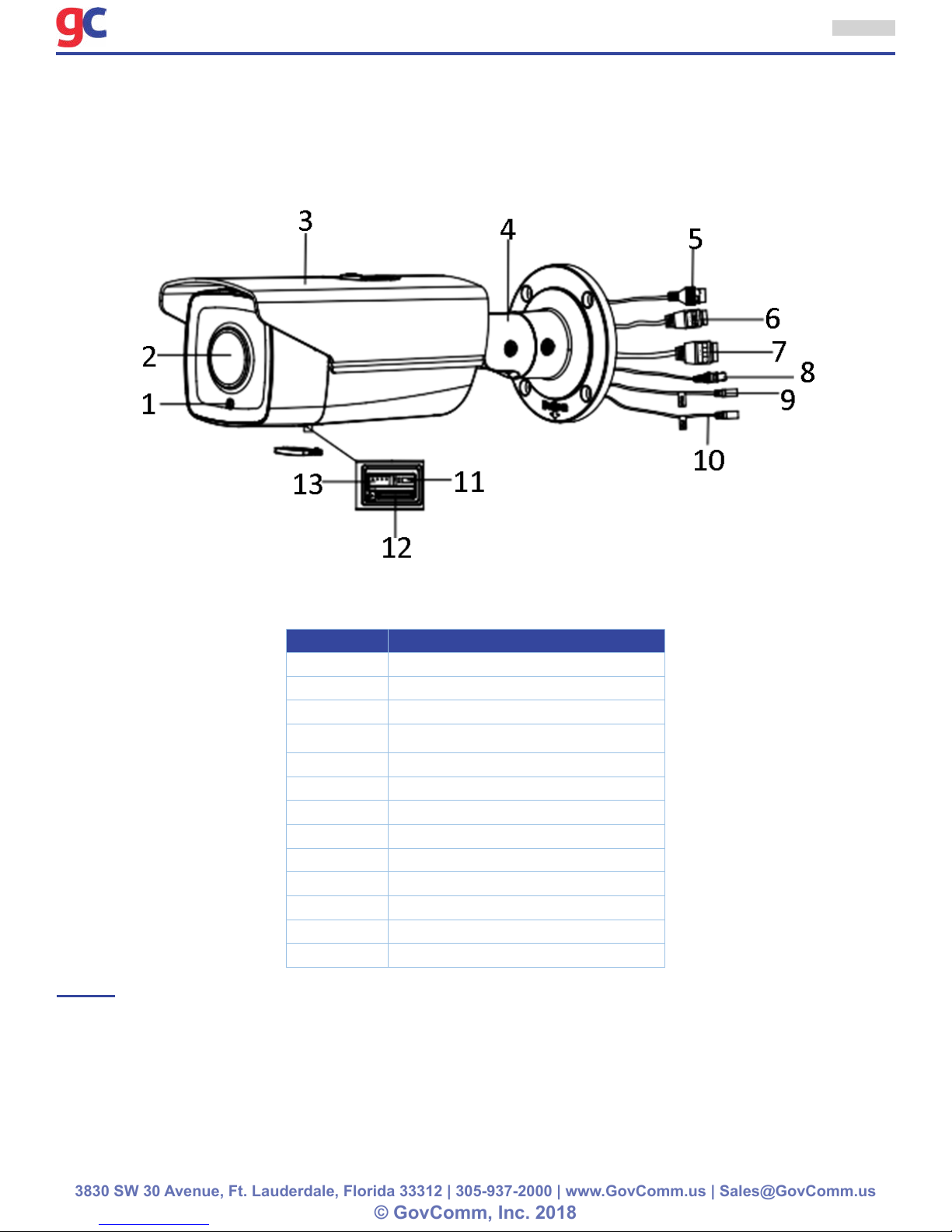
1 Appearance Description
1.1 Overview
The overview of the network bullet camera is shown below.
5
Figure 1-1 Overview
Table 1-1 Description
No. Description
1 Photoresistor
2 Lens
3
4 3-axis Bracket
5
6
7
8
9
10
11
12
13
Network Cable Interface
Sun Shield
Power Cable Interface
Alarm Cable Interface
Video Cable Interface
Audio Out
Audio In
Reset Button
Micro SD Card Slot
Serial Port
NOTE:
• The standard power supply is 12V DC or 24V AC, please make sure your power supply matches
with your camera.
• Press RESET about 10s when the camera is powering on or rebooting to restore the default
settings, including the user name, password, IP address, port No., etc.
Page 6

External Postioner (Fixed) Camera - Quick Start Guide
3830 SW 30 Avenue, Ft. Lauderdale, Florida 33312 | 305-937-2000 | www.GovComm.us | Sales@GovComm.us
© GovComm, Inc. 2018
6
1.2 Micro SD Card Installation
This series of camera supports micro SD card installation. Please follow the steps below to install the
micro SD card.
1. Loosen the two lock screws at the bottom of the bullet camera, and then remove the slot cover.
Figure 1-2 Remove Card Cover
2. Insert the SD card into the SD card slot.
Figure 1-3 Insert the Card
3. (Optional) Push the inserted micro SD card inside to remove the micro SD card.
Re-install the card cover and fasten the two screws to complete the installation.
1.3 Initializing the Memory Card
Steps:
Check the memory card status by tapping on the Storage Status in the Device Settings interface.
If the memory card status displays as Uninitialized, tap to initialize it. The status will then change to
Normal. You can then start recording any event triggered video in the camera such as motion detection.
Page 7

External Postioner (Fixed) Camera - Quick Start Guide
3830 SW 30 Avenue, Ft. Lauderdale, Florida 33312 | 305-937-2000 | www.GovComm.us | Sales@GovComm.us
© GovComm, Inc. 2018
7
2 Installation
Before you start:
• Make sure the device in the package is in good condition and all the assembly parts are included.
• The standard power supply is 12V DC or 24V AC, please make sure your power supply matches with
your camera.
• Make sure all the related equipment is power-off during the installation.
• Check the specication of the products for the installation environment.
• Make sure that the wall is strong enough to withstand four times the weight of the camera and the
bracket.
For the camera that supports IR, you are required to pay attention to the following precautions to
prevent IR reection:
• Dust or grease on the dome cover will cause IR reection. Please do not remove the dome cover lm
until the installation is nished. If there is dust or grease on the dome cover, clean the dome cover
with clean soft cloth and isopropyl alcohol.
• Make sure that there is no reective surface too close to the camera lens. The IR light from the
camera may reect back into the lens causing reection.
• The foam ring around the lens must be seated ush against the inner surface of the bubble to isolate
the lens from the IR LEDS. Fasten the dome cover to camera body so that the foam ring and the
dome cover are attached seamlessly.
2.1 Ceiling Mounting
Steps:
1. Drill the screw holes and the cable hole in the ceiling according to the supplied drill template.
Figure 2-1 Drill Template
2. Fix the camera to the wall with the supplied screws.
Page 8

External Postioner (Fixed) Camera - Quick Start Guide
3830 SW 30 Avenue, Ft. Lauderdale, Florida 33312 | 305-937-2000 | www.GovComm.us | Sales@GovComm.us
© GovComm, Inc. 2018
8
NOTE: Please insert the expansion screws rst if the camera is mounted to the cement ceiling. And you
can use the self-tapping screws directly if camera is mounted to the wooden ceiling.
Figure 2-2 Install the Camera
3. Adjust the surveillance angle.
» 1). Loosen No.1 lock screw to adjust the tilt angle [0 °~100°].
» 2). Loosen No.2 lock screw to adjust the pan angle [0°~360°].
» 3). Loosen No.3 lock screw to rotate the camera [0°~360°].
» 4). Tighten the lock screws.
NOTE: A wrench is supplied to loosen and tighten the screws.
Figure 2-3 Adjust the Surveillance Angle
Figure 2-4 Supplied Wrench
Page 9

External Postioner (Fixed) Camera - Quick Start Guide
3830 SW 30 Avenue, Ft. Lauderdale, Florida 33312 | 305-937-2000 | www.GovComm.us | Sales@GovComm.us
© GovComm, Inc. 2018
9
4. (Optional) Install the water-proof jacket for network interface.
NOTE: It is recommended to adopt the water-proof jacket (supplied) for the network interface when the
camera is installed outdoor.
» 1). If the network cable has been settled down, cut off the plug of the network cable rst.
» 2). Route the network cable through the following components in sequence: x nut, water-proof
ring, and the main body of the water-proof jacket, as shown in the gure.
» 3). Insert the water-proof ring into the main body of the water-proof jacket, to increase the sealing
ability of the components.
» 4). Wire the plug and network cables up.
» 5). Fix the O-ring to the network interface of the camera, and then connect the network cables.
» 6). Wrap the network interface with the main body of the water-proof jacket, and then rotate the
x nut clockwise to assemble it to the main body of the water-proof jacket.
Figure 2-5 Install the Water-proof Jacket
2.2 Wall Mounting with a Junction Box
Steps:
1. Drill the screw hole and cable hole according to the supplied drill template (shown as Figure 2-1).
2. Align the screw holes of the junction box to the drill template, and x the junction box to the wall
with screws.
3. Route the cables.
4. Fix the camera to the junction box with screws.
5. Adjust the surveillance angle according to step 3 in Chapter 2.1.
6. Install the water-proof jacket according to step 4 in Chapter 2.1.
Figure 2-6 Installation with a Junction Box
Page 10

External Postioner (Fixed) Camera - Quick Start Guide
3830 SW 30 Avenue, Ft. Lauderdale, Florida 33312 | 305-937-2000 | www.GovComm.us | Sales@GovComm.us
© GovComm, Inc. 2018
2.3 Wall Mounting with a Gang Box
NOTE: An adapter plate should be purchased separately if you mount the camera to a gang box.
Steps:
1. Install the adapter plate to the gang box.
2. Route the cables.
3. Fix the camera to the adapter plate with screws.
4. Adjust the surveillance angle according to step 3 in Chapter 2.1.
5. Install the water-proof jacket according to step 4 in Chapter 2.1.
10
Figure 2-7 Installation with a Gang Box
Page 11

External Postioner (Fixed) Camera - Quick Start Guide
3830 SW 30 Avenue, Ft. Lauderdale, Florida 33312 | 305-937-2000 | www.GovComm.us | Sales@GovComm.us
© GovComm, Inc. 2018
3 Setting the Network Camera over the LAN
NOTE: You shall acknowledge that the use of the product with Internet access might be under
network security risks. For avoidance of any network attacks and information leakage, please
strengthen your own protection.
If the product does not work properly, contact your dealer or the nearest service center for help.
3.1 Wiring
Connect the camera to network according to the following gures.
Figure 3-1 Connecting Directly
11
Figure 3-2 Connecting via a Switch or a Router
3.2 Activating the Camera
You are required to activate the camera rst by setting a strong password for it before you can use
the camera.
Activation via Web Browser, Activation via SADP, and Activation via Client Software are all supported.
We will take activation via SADP software and Activation via Web Browser as examples to introduce
the camera activation.
NOTE: Refer to the User Manual of Network Camera for Activation via Client Software.
3.2.1 Activation via Web Browser
Steps:
1. Power on the camera. Connect the camera to your computer or the switch/router which your
computer connects to.
2. Input the IP address into the address bar of the web browser, and press Enter to enter the
activation interface.
Page 12

External Postioner (Fixed) Camera - Quick Start Guide
3830 SW 30 Avenue, Ft. Lauderdale, Florida 33312 | 305-937-2000 | www.GovComm.us | Sales@GovComm.us
© GovComm, Inc. 2018
12
NOTES:
• The default IP address of the camera is 192.168.1.64.
• The computer and the camera should belong to the same subnet.
• For the camera enables the DHCP by default, you need to use the SADP software to search the IP
address.
Figure 3-3 Activation Interface (Web)
3. Create a password and input the password into the password eld.
STRONG PASSWORD RECOMMENDED– We
highly recommend you create a strong password
of your own choosing (using a minimum of 8
characters, including upper case letters, lower
case letters, numbers, and special characters) in
order to increase the security of your product. And
we recommend you reset your password regularly,
especially in the high security system, resetting
the password monthly or weekly can better protect
your product.
4. Conrm the password.
5. Click OK to save the password and enter the live view interface.
3.2.2 Activation via SADP Software
SADP software is used for detecting the online device, activating the camera, and resetting the password.
Get the SADP software from the supplied disk or the ofcial website, and install the SADP according
to the prompts.
Follow the steps to activate the camera.
Steps:
1. Run the SADP software to search the online devices.
2. Check the device status from the device list, and select the inactive device.
Page 13

External Postioner (Fixed) Camera - Quick Start Guide
3830 SW 30 Avenue, Ft. Lauderdale, Florida 33312 | 305-937-2000 | www.GovComm.us | Sales@GovComm.us
© GovComm, Inc. 2018
Figure 3-4 SADP Interface
13
NOTE: The SADP software supports activating the camera in batch. Refer to the user manual of
SADP software for details.
3. Create and input the new password in the password eld, and conrm the password.
STRONG PASSWORD RECOMMENDED– We
highly recommend you create a strong password
of your own choosing (using a minimum of 8
characters, including upper case letters, lower
case letters, numbers, and special characters) in
order to increase the security of your product. And
we recommend you reset your password regularly,
especially in the high security system, resetting
the password monthly or weekly can better protect
your product.
4. Click Activate to start activation.
You can check whether the activation is completed on the popup window. If activation failed, make
sure that the password meets the requirement and try again.
3.3 Modifying the IP Address
Purpose:
To view and congure the camera via LAN (Local Area Network), you need to connect the network
camera in the same subnet with your PC.
Use the SADP software or client software to search and change the IP address of the device.
We take modifying the IP Address via SADP software as an example to introduce the IP address
modication.
Page 14

External Postioner (Fixed) Camera - Quick Start Guide
3830 SW 30 Avenue, Ft. Lauderdale, Florida 33312 | 305-937-2000 | www.GovComm.us | Sales@GovComm.us
© GovComm, Inc. 2018
For IP address modication via client software, refer to the user manual of client software.
Steps:
1. Run the SADP software.
2. Select an active device.
3. Change the device IP address to the same subnet with your computer by either modifying the IP
address manually or checking the checkbox of Enable DHCP.
14
Figure 3-5 Modify the IP Address
4. Input the admin password and click Modify to activate your IP address modication.
The batch IP address modication is supported by the SADP. Refer to the user manual of SADP for
details.
Page 15

External Postioner (Fixed) Camera - Quick Start Guide
3830 SW 30 Avenue, Ft. Lauderdale, Florida 33312 | 305-937-2000 | www.GovComm.us | Sales@GovComm.us
© GovComm, Inc. 2018
15
4 Accessing via Web Browser
System Requirements:
Operating System: Microsoft Windows XP SP1 and above version CPU: 2.0 GHz or higher
RAM: 1G or higher
Display: 1024×768 resolution or higher
Web Browser: Internet Explorer 8.0 and above version, Apple Safari 5.0.2 and above version, Mozilla
Firefox 5.0 and above version and Google Chrome 18 and above version
Steps:
1. Open the web browser.
2. In the browser address bar, input the IP address of the network camera, and press the Enter key
to enter the login interface.
NOTE: The default IP address is 192.168.1.64. You are recommended to change the IP address to
the same subnet with your computer.
3. Input the user name and password.
The admin user should congure the device accounts and user/operator permissions properly. Delete
the unnecessary accounts and user/operator permissions.
NOTE: The device IP address gets locked if the admin user performs 7 failed password attempts (5
attempts for the user/operator).
4. Click Login.
Figure 4-1 Modify the IP Address
5. Install the plug-in before viewing the live video and managing the camera. Follow the installation
prompts to install the plug-in.
NOTE: You may have to close the web browser to nish the installation of the plug-in.
Figure 4-2 Modify the IP Address
Page 16

External Postioner (Fixed) Camera - Quick Start Guide
3830 SW 30 Avenue, Ft. Lauderdale, Florida 33312 | 305-937-2000 | www.GovComm.us | Sales@GovComm.us
© GovComm, Inc. 2018
16
6. Reopen the web browser after the installation of the plug-in and repeat steps 2 to 4 to login.
NOTE: For detailed instructions of further conguration, please refer to the user manual of network
camera.
 Loading...