

GOVCOMM GC-ICPO-FIZ6DE, GC-ICPO-FIZ23L, GC-IMPO-FIZ6DE, GC-IMPO-FIZDE, GC-IMPO-FI2DE Installation And User Manual
...
ITS Camera Systems
Installation and User Manual
Sales@GovComm.us | 305-937-2000 | 2650 Biscayne Blvd, Miami, Florida 33137
© GovComm, Inc. 2017

Thank you for purchasing GovComm’s network ITS Camera product. If there are any technical or general
questions, concerns or requests, please contact us through our website www.GovComm.us, by email Sales@
GovComm.us or by telephone 1+305-937-2000.
This manual may contain several technical or printing errors, and the content is subject to change without notice.
We regularly improve and update our products and procedures described in the manual. Updates will be added
to new versions of this manual and posted onto the GovComm website.
DISCLAIMER STATEMENT
“Underwriters Laboratories, Inc. (“UL”) has not tested the performance or reliability of the security or signaling
aspects of this product. UL has only tested for re, shock or casualty hazards as outlined in UL’s Standard(s)
for Safety, UL60950-1. UL Certication does not cover the performance or reliability of the security or signaling
aspects of this product. UL MAKES NO REPRESENTATIONS, WARRANTIES OR CERTIFICATIONS
WHATSOEVER REGARDING THE PERFORMANCE OR RELIABILITY OF ANY SECURITY OR SIGNALING
RELATED FUNCTIONS OF THIS PRODUCT.”
Regulatory Information
FCC Information
FCC compliance: This equipment has been tested and found to comply with the limits for a digital device,
pursuant to part 15 of the FCC Rules. These limits are designed to provide reasonable protection against
harmful interference when the equipment is operated in a commercial environment. This equipment generates,
uses, and can radiate radio frequency energy and, if not installed and used in accordance with the instruction
manual, may cause harmful interference to radio communications. Operation of this equipment in a residential
area is likely to cause harmful interference in which case the user will be required to correct the interference at
his own expense.
FCC Conditions
This device complies with part 15 of the FCC Rules. Operation is subject to the following two conditions:
Safety Instruction
These instructions are intended to ensure that the user can use the product correctly to avoid danger
or property loss.
The precaution measure is divided into ‘Warnings’ and ‘Cautions’:
Warnings: Serious injury or death may be caused if any of these warnings areneglected.
Warnings: Follow these safeguards to prevent
serious injury or death.
Sales@GovComm.us | 305-937-2000 | 2650 Biscayne Blvd, Miami, Florida 33137
Cautions: Follow these precautions to prevent
potential injury or material damage.
© GovComm, Inc. 2017

Warnings:
• Please use the power transformer or power converter with PoE injector supplied, both of which
meet applicable safety standards. The power consumption cannot be less than the required value.
• Do not connect several devices to one power adapter as an adapter overload may cause over-
heating and can be a re hazard.
• The device should be rmly xed to a sturdy structure.
• To reduce the risk of re or electrical shock, do not expose a product designed for indoor use to rain
or moisture.
• This installation should be made by a qualied service person and should conform to all the local
codes.
• We recommend installation of a back-up power supply in the event of electrical supply interruption.
• If the product does not work properly, please contact GovComm. Never attempt to disassemble
the product yourself. (GovComm does not assume any responsibility for problems caused by
unauthorized repair or maintenance.)
Cautions:
• Make sure the power supplied is the correct voltage (110 if powered AC or 24/48 if powered DC)
and current (AC if powered 24VAC or DC if powered w/ Moxa PoE injector).
• Although the camera has been tested for and can withstand shock and vibration, dropping the
camera, subjecting it to physical shock and installing the camera on vibratory surfaces or places is
not recommended.
• Do not expose the camera to high electromagnetic radiating environment.
• Do not aim the lens at strong light such as the sun or an incandescent lamp. Strong light can cause
fatal damage.
• The camera’s sensor may be burned out by a laser beam.
• Do not place the dome in extremely hot, cold, dusty or damp locations, otherwise re or electrical
shock will occur. The operating temperature should be -40°C ~ 75°C.
• While shipping, the product should be packed in its original packing.
• Please use the provided glove when opening up the product cover. Do not touch the product cover
with ngers directly, because the acidic sweat of the ngers may erode the surface coating of the
product cover.
• Please use a soft and dry cloth when cleaning inside and outside surfaces of the product cover. Do
not use alkaline detergents.
Sales@GovComm.us | 305-937-2000 | 2650 Biscayne Blvd, Miami, Florida 33137
© GovComm, Inc. 2017

Table of Contents
1.0 Overview . . . . . . . . . . . . . . . . . . . . . . . . . . . . . . . . . . . . . . . . . . . . . . . . . . . . . . . . . . . . . . . 1
1.1 Opening and Installing a GovComm Camera. . . . . . . . . . . . . . . . . . . . . . . . . . . . . 2
1.2 PoE, PoE+ and High POE . . . . . . . . . . . . . . . . . . . . . . . . . . . . . . . . . . . . . . . . . . . . . . . 3
1.3 Conguring Compass Application on GovComm PTZ Camera. . . . . . . . . . . . 3
1.4 Focus Distance Conguration for GovComm PTZ Cameras Explained. . . . 5
1.5 Recording Videos and Capturing Screen Shots from Browser. . . . . . . . . . . . 6
1.6 Steps to Troubleshoot IP Camera. . . . . . . . . . . . . . . . . . . . . . . . . . . . . . . . . . . . . . . . 8
1.7 Troubleshooting GovComm ITS Cameras. . . . . . . . . . . . . . . . . . . . . . . . . . . . . . . .11
2.0 PTZ Conguration . . . . . . . . . . . . . . . . . . . . . . . . . . . . . . . . . . . . . . . . . . . . . . . . . . 12
2.1 Conguring Initial Position . . . . . . . . . . . . . . . . . . . . . . . . . . . . . . . . . . . . . . . . . . . . 12
2.2 Conguring Basic PTZ Parameters . . . . . . . . . . . . . . . . . . . . . . . . . . . . . . . . . . . . . 12
2.3 Conguring PTZ Limit Stops . . . . . . . . . . . . . . . . . . . . . . . . . . . . . . . . . . . . . . . . . . 14
2.4 Conguring Scheduled Tasks . . . . . . . . . . . . . . . . . . . . . . . . . . . . . . . . . . . . . . . . . . 15
2.5 Conguring Park Actions . . . . . . . . . . . . . . . . . . . . . . . . . . . . . . . . . . . . . . . . . . . . . . 16
2.6 Conguring Privacy Mask . . . . . . . . . . . . . . . . . . . . . . . . . . . . . . . . . . . . . . . . . . . . . . 17
2.7 Conguring Smart Tracking . . . . . . . . . . . . . . . . . . . . . . . . . . . . . . . . . . . . . . . . . . . . 18
2.8 Clearing PTZ Congurations. . . . . . . . . . . . . . . . . . . . . . . . . . . . . . . . . . . . . . . . . . . 18
3.0 ITS Camera Conguration . . . . . . . . . . . . . . . . . . . . . . . . . . . . . . . . . . . . . . . . . 19
3.1 Conguring Local Parameters . . . . . . . . . . . . . . . . . . . . . . . . . . . . . . . . . . . . . . . . . 19
3.2 Conguring Time Settings . . . . . . . . . . . . . . . . . . . . . . . . . . . . . . . . . . . . . . . . . . . . . 20
3.3 Conguring Network Settings . . . . . . . . . . . . . . . . . . . . . . . . . . . . . . . . . . . . . . . . . . 22
3.3.1 Conguring TCP/IP Settings . . . . . . . . . . . . . . . . . . . . . . . . . . . . . . . . . . . . . . . . . . . 22
3.3.2 Conguring Port Settings . . . . . . . . . . . . . . . . . . . . . . . . . . . . . . . . . . . . . . . . . . . . . 23
3.3.3 Conguring PPPoE Settings . . . . . . . . . . . . . . . . . . . . . . . . . . . . . . . . . . . . . . . . . . . 24
3.3.4 Conguring DDNS Settings . . . . . . . . . . . . . . . . . . . . . . . . . . . . . . . . . . . . . . . . . . . 24
3.3.5 Conguring SNMP Settings . . . . . . . . . . . . . . . . . . . . . . . . . . . . . . . . . . . . . . . . . . . 26
3.3.6 Conguring 802.1X Settings . . . . . . . . . . . . . . . . . . . . . . . . . . . . . . . . . . . . . . . . . . . 27
3.3.7 Conguring QoS Settings . . . . . . . . . . . . . . . . . . . . . . . . . . . . . . . . . . . . . . . . . . . . . 28
3.3.8 Conguring FTP Settings . . . . . . . . . . . . . . . . . . . . . . . . . . . . . . . . . . . . . . . . . . . . . 28
3.3.9 Conguring NAT Settings . . . . . . . . . . . . . . . . . . . . . . . . . . . . . . . . . . . . . . . . . . . . . 29
3.3.10 Conguring Email Settings . . . . . . . . . . . . . . . . . . . . . . . . . . . . . . . . . . . . . . . . . . 30
3.4 Conguring Video and Audio Settings . . . . . . . . . . . . . . . . . . . . . . . . . . . . . . . . . 31
3.4.1 Conguring Video Settings . . . . . . . . . . . . . . . . . . . . . . . . . . . . . . . . . . . . . . . . . . . 31
3.4.2 Conguring Audio Settings. . . . . . . . . . . . . . . . . . . . . . . . . . . . . . . . . . . . . . . . . . . . 33
3.4.3 Conguring ROI Settings. . . . . . . . . . . . . . . . . . . . . . . . . . . . . . . . . . . . . . . . . . . . . . 33
3.5 Conguring Image Settings . . . . . . . . . . . . . . . . . . . . . . . . . . . . . . . . . . . . . . . . . . . . 34
3.5.1 Conguring Display Settings . . . . . . . . . . . . . . . . . . . . . . . . . . . . . . . . . . . . . . . . . . 34
3.5.2 Conguring OSD Settings . . . . . . . . . . . . . . . . . . . . . . . . . . . . . . . . . . . . . . . . . . . . 40
3.5.3 Conguring Text Overlay Settings . . . . . . . . . . . . . . . . . . . . . . . . . . . . . . . . . . . . . . 41
Sales@GovComm.us | 305-937-2000 | 2650 Biscayne Blvd, Miami, Florida 33137
© GovComm, Inc. 2017

3.6 Conguring and Handling Alarms . . . . . . . . . . . . . . . . . . . . . . . . . . . . . . . . . . . . . . 42
3.6.1 Conguring Motion Detection . . . . . . . . . . . . . . . . . . . . . . . . . . . . . . . . . . . . . . . . . . 42
3.6.2 Conguring Video Loss Alarm . . . . . . . . . . . . . . . . . . . . . . . . . . . . . . . . . . . . . . . . . 44
3.6.3 Conguring Tamper-proof Alarm . . . . . . . . . . . . . . . . . . . . . . . . . . . . . . . . . . . . . . . 45
3.6.4 Conguring External Alarm Input . . . . . . . . . . . . . . . . . . . . . . . . . . . . . . . . . . . . . . 47
3.6.5 Conguring Alarm Output . . . . . . . . . . . . . . . . . . . . . . . . . . . . . . . . . . . . . . . . . . . . 48
3.6.6 Handling Exception . . . . . . . . . . . . . . . . . . . . . . . . . . . . . . . . . . . . . . . . . . . . . . . . . . 49
Sales@GovComm.us | 305-937-2000 | 2650 Biscayne Blvd, Miami, Florida 33137
© GovComm, Inc. 2017
ITS Camera System - Installation and User Manual
2650 Biscayne Boulevard, Miami, Florida 33137 | 305-937-2000 | www.GovComm.us | Sales@GovComm.us
© GovComm, Inc. 2017
1.0 Overview
1
System Requirement
System requirement of web browser accessing is as follows:
Operating System: Microsoft Windows XP SP1 and above version / Vista / W in7 / Server 2003 /
Server 2008 32bits
CPU: Intel Pentium IV 3.0 GHz or higher
RAM: 1G or higher
Display: 1024×768 resolution or higher
Web Browser: Internet Explorer 7.0 and above version, Apple Safari 5.02 and above version, Mozilla
Firefox 3.5 and above version.

ITS Camera System - Installation and User Manual
2650 Biscayne Boulevard, Miami, Florida 33137 | 305-937-2000 | www.GovComm.us | Sales@GovComm.us
© GovComm, Inc. 2017
2
1.1 Opening and Installing a GovComm Camera
1. Before powering up a GovComm ITS camera, make sure to follow these important steps to
avoid damage:
» Open the camera and remove the protective foam. Remove the tape inside and outside the
camera housing.
» NEVER pick-up or otherwise handle a GovComm ITS camera by the wiring harness. This may
break the top seal, compromise the camera’s integrity and invalidate the warranty. A lifting ring
and cable is provided for handling.
» Ensure that all the gaskets are inline when sealing the dome enclosure. Make sure that the
dome is fully closed by pressing down around the metal ring on the cameras circumference. DO
NOT press on the clear enclosure.
» Hand tighten exterior screws after sealing the dome enclosure. We recommend not using
power tools, but tightening with a screwdriver. A power tool may strip the enclosures thread
or otherwise compromise the integrity of the cameras seal.Connect the ITS camera to the
appropriate power source. Either of these options will work with all GovComm ITS cameras:
2. Connect the ITS camera to the appropriate power source. Either of these options will work
with all GovComm ITS cameras:
» GovComm Supplied 24 VAC Transformer - Separate cabling is required. Power is connected
to the red and black solid cables. We suggest grounding the camera using the yellow / green
cable. Make sure to use the appropriate gauge (16 or 18 gauge ok up to 300’) cable considering
distance.
» GovComm Supplied Moxa INJ-24A-T Wide Temperature PoE Injector. Make sure the injector is
congured for 4 pair and HiPoE by conguring the DIP switches.
3. Download the discovery tool from http://govcomm.us/downloads/SADPTool.zip.
» All GovComm cameras that are connected to the same switch (Layer 2 network even if the IP
address of the camera is different from the IP schema). The default IP address for GovComm
ITS cameras is http://192.168.1.64
» Activate camera if needed.
» Change the IP address. Make sure to enter the password before saving the new settings.
4. Open a browser (Internet Explorer or FireFox) and go to the ITS camera’s IP address.
*NOTICE* A Chrome browser version newer than 08/2015 does not work as Chrome does not
allow the plugin used by our ITS camera. Only Internet Explorer and FireFox are compatible with
GovComm ITS cameras.
Make sure the computer allows third party plugins to be installed. Also, make sure to close the
browser before starting to install the plugin.

ITS Camera System - Installation and User Manual
2650 Biscayne Boulevard, Miami, Florida 33137 | 305-937-2000 | www.GovComm.us | Sales@GovComm.us
© GovComm, Inc. 2017
» All GovComm ITS cameras come with a default username and password.
» Username: admin
» Password: GovComm1
» Open ther browser and go the camera’s IP address again.
» Allow the plugin to run. Make sure to add the camera’s IP address to the trusted sites to capture
snap shots and record video locally.
1.2 PoE, PoE+ and High POE
• GovComm PTZ Eagle cameras use 24 VAC or High PoE only.
• GovComm PTZ Hawk cameras use 24VAC or PoE+ (35 W) or High PoE (60 W= 2 x 30W
channels). PoE+ uses 4 wires mid-span to power the camera while High PoE uses all 8 wires (4
pairs).
3
• GovComm cameras use:
End-span - 1,2 (+); 3,6 (-)
Mid-span - 4,5 (+), 7,8 (-)
• Some other cameras (AXIS for example) use different polarity ( http://tyconpower.com/products/
les/TP-DCDC-xx56GD-VHP_Spec_Sheet.pdf )
End-span - 1,2 (-); 3,6 (+)
Mid-span - 4,5 (+), 7,8 (-)
1.3 Conguring Compass Application on GovComm PTZ Camera
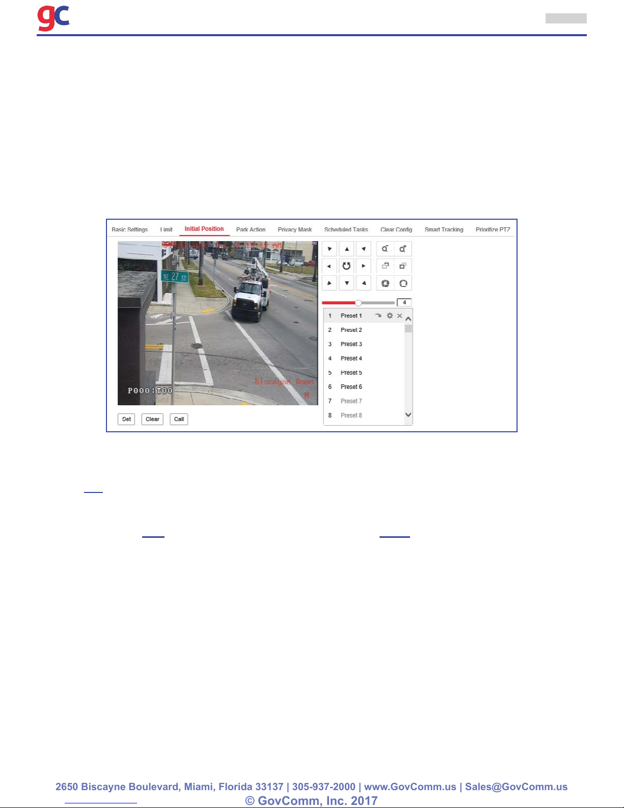
In addition to numerical values for pan-tilt-zoom positions, our ITS camera also displays cardinal direction (e.g. N, S, E & W) when controlled with NTCIP commands. To setup the compass, follow the
following procedure:
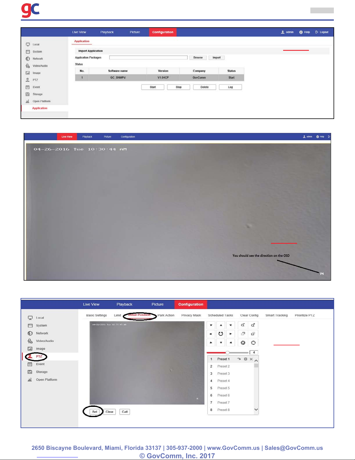
1. Make sure the application is started (see Picture 1)
2. Make sure the cardinal direction is showing on Live view (see Picture 2)
3. Navigate to the “Live View” tab and position the camera’s view to North.
4. Navigate to Conguration > PTZ > Initial Position and click Set. This sets the current position as
North (0°). Subsequent pan movements will alter the internal compass and change the value
displayed as appropriate (Image 3).
ITS Camera System - Installation and User Manual
2650 Biscayne Boulevard, Miami, Florida 33137 | 305-937-2000 | www.GovComm.us | Sales@GovComm.us
© GovComm, Inc. 2017
4
Image 1
Image 2
Image 3
ITS Camera System - Installation and User Manual
2650 Biscayne Boulevard, Miami, Florida 33137 | 305-937-2000 | www.GovComm.us | Sales@GovComm.us
© GovComm, Inc. 2017
5
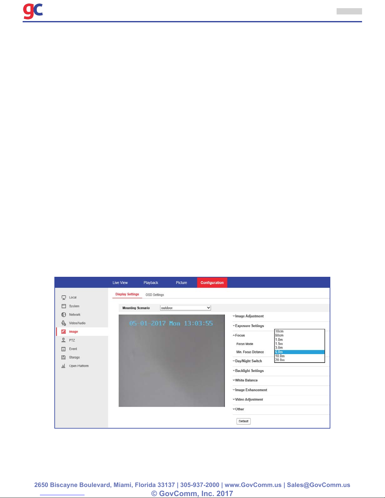
1.4 Focus Distance Conguration for GovComm PTZ Cameras Explained
When adjusting the focus there are several rules to follow:
To make changes to the focus settings, visit the web interface: Conguration >Image >Focus
Settings. The user will see drop down menus for “Focus Mode” and “Min Focus Distance” (see attached
screenshot)
1. “Focus Mode” has the following options: Auto - Semi-Auto - Manual
• When on “Auto” the camera will constantly adjust the focus whether the camera is moving or not. The
sensors are always engaged and the focus will adjust to changes of scenery.
• When on “Semi-Auto” the camera’s focus will adjust only once after a PTZ function is engaged and
will not readjust until a subsequent PTZ function is performed. When the camera is not moving, the
focus can be adjusted manually from the focus control buttons.
• When on “Manual” the camera will never adjust automatically. The focus can be adjusted manually
from the focus control buttons.
2. GovComm ITS cameras come with several minimum focus distance options which is where the
automatic focus begins to engage. On a windy day, a tree’s branches waving within the minimum
focus distance can cause erratic engaging and disengaging of the automatic focus, so the user can
set a further minimum focus distance to avoid unnecessary adjustments and image degradation.
When our ITS cameras are installed on high poles, we recommend that the minimum focus distance
be set at 10m (30 feet) or greater..
ITS Camera System - Installation and User Manual
2650 Biscayne Boulevard, Miami, Florida 33137 | 305-937-2000 | www.GovComm.us | Sales@GovComm.us
© GovComm, Inc. 2017
6
1.5 Recording Videos and Capturing Screen Shots from Browser
When viewing, recording and capturing snapshots the camera using Internet Explorer 10 or 11, sometimes the content may not display, record or capture properly. IE 10 and 11 does not support plugins or
ActiveX components. Follow the instructions bellow for the content to work properly:
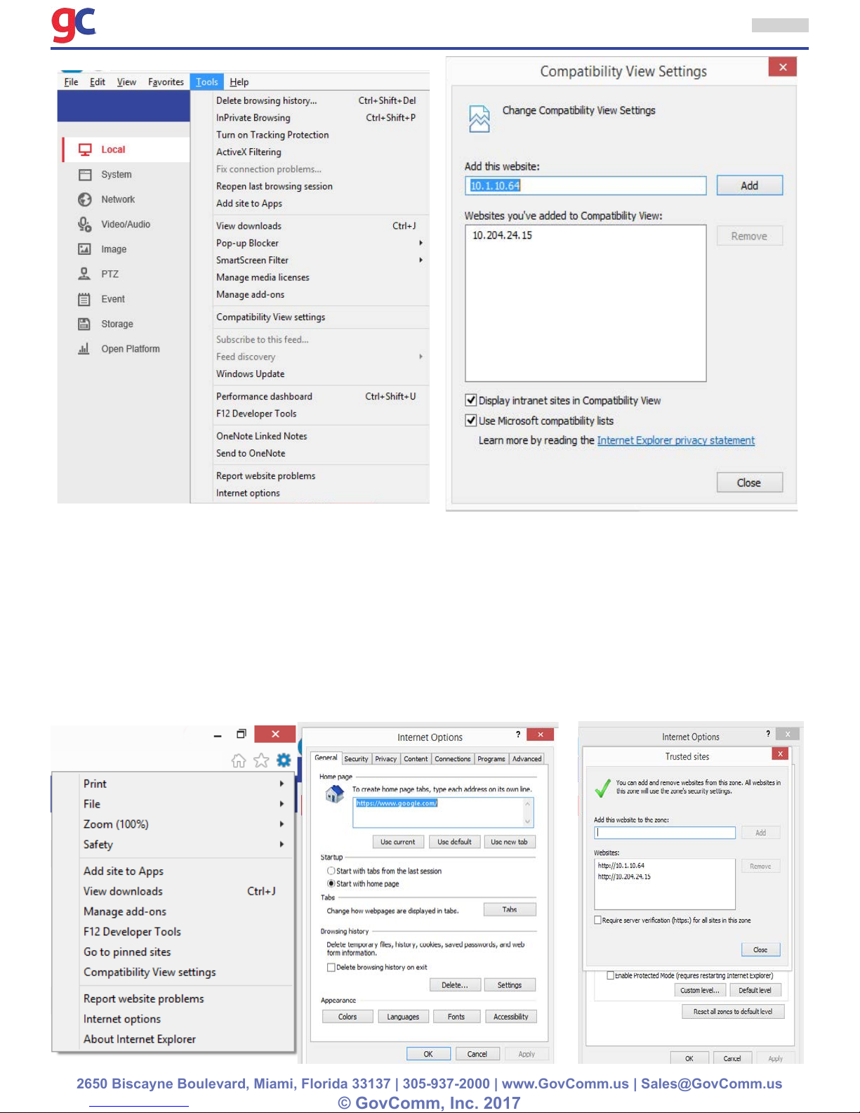
• Step 1: Add a site to the Compatibility View list
1. Open Internet Explorer.
2. Press the Alt key on the keyboard to display the Menu bar.
3. Click Tools, click the Compatibility View settings.
4. In the Compatibility View Settings window, under Add this website, enter the address of the device to
add to the list, and then click the Add button. (NOTE: The current webpage address will automatically
be lled in. Just clear it to add a different address instead).
5. At the bottom of the window, make sure the box next to Display intranet sites in Compatibility View
is checked.
6. Click the Close button.
7. For the changes to take effect, Internet Explorer may need to be closed and restarted.
Note: If there are still issues with Internet Explorer proceed to step 2.
• Step 2: Add a site to the Trusted sites list
1. Open Internet Explorer.
2. Press the Alt key to display the Menu bar.
3. Click Tools.
4. In the Tools menu, select Internet Options.
5. In the Internet Options window, click the Security tab.
6. On the Security tab, click the Trusted sites icon.
7. Click the Sites button.
ITS Camera System - Installation and User Manual
2650 Biscayne Boulevard, Miami, Florida 33137 | 305-937-2000 | www.GovComm.us | Sales@GovComm.us
© GovComm, Inc. 2017
7
8. In the Trusted sites window, uncheck the Require server verication (https:) for all sites in this
zone option if it is not connecting via HTTPS.
9. In the Add this website to the zone box, type the address of the device that needs to be accessed
and click the Add button. (NOTE: The current webpage address will automatically be lled in. Just
clear it to add a different address instead).
10. Click the Close button.
11. In the Internet Options windows, click OK.
12. For the changes to take effect, all open browsers may need to restart.
ITS Camera System - Installation and User Manual
2650 Biscayne Boulevard, Miami, Florida 33137 | 305-937-2000 | www.GovComm.us | Sales@GovComm.us
© GovComm, Inc. 2017
8
1.6 Steps to Troubleshoot IP Camera
The Top Ten Tips of Troubleshooting
1. Reboot the camera
2. Ping & discover the camera
3. Check ARP tables
4. Check for IP conicts
5. Disable antivirus software and rewalls
6. Verify camera power & connection
7. Check the cabling
8. Know the password
9. Look to the manufacturer for help
10. Reset the camera to factory default
Tips Explained
1. Reboot the Camera: Some consider the ‘Golden Rule’ of IT troubleshooting to rst reboot the
device before proceeding. Simply restarting the camera gives the chance for cache to ush, settings
to recalibrate, and connections to be renegotiated. This step is the least difcult and cheapest to
perform, one only has to remove power, wait 10 or 15 seconds, and then restore power.
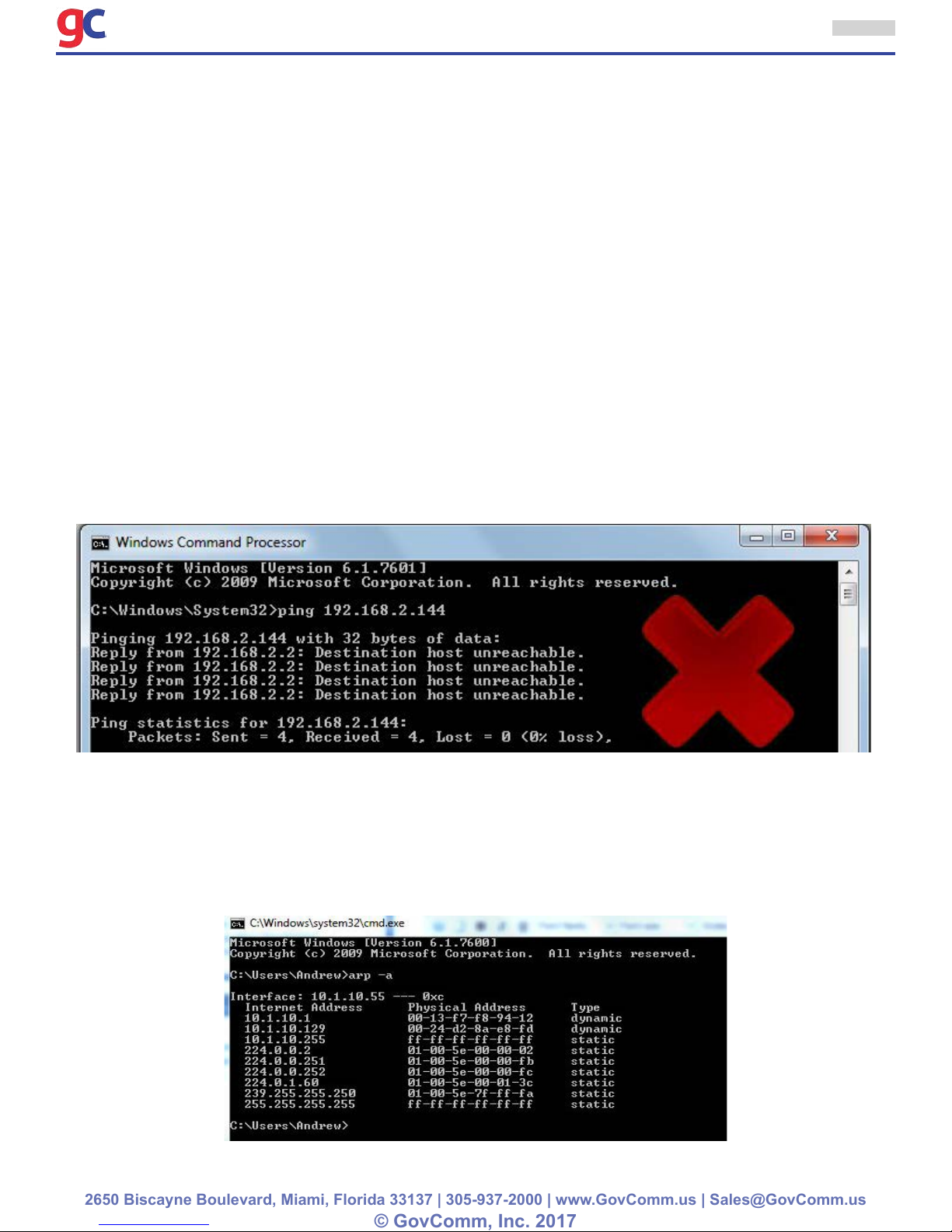
2. Ping the camera and discover it: Type “cmd” into the Windows search box to open a DOS command
prompt and the use the “ping” command to see if there is a connection to the camera. For example, if
the camera’s address is 192.168.2.150, use “ping 192.168.2.150 -t” at the command prompt, if there
are responses of “Destination Host Unreachable” or “Request Timed Out” replies that means there
is no connection via the network. There can be many reasons for that, the most common being that
the camera and the computer are on different networks or subnets. If there are proper connection
replies, use a web browser forthe camera.
ITS Camera System - Installation and User Manual
2650 Biscayne Boulevard, Miami, Florida 33137 | 305-937-2000 | www.GovComm.us | Sales@GovComm.us
© GovComm, Inc. 2017
9
3. Check ARP tables to cross reference MAC and IP addresses: Knowing the camera’s MAC
address is a vital clue to discovering a camera’s IP address, it’s usually printed somewhere on most
units on the camera or housing. It’s good practice to keep a record of the MAC and IP addresses of
installed cameras for troubleshooting purposes. In a similar manner to ping in Tip #2 above, the ARP
command can be used to show the IP and MAC addresses of devices connected to the network, just
type “arp -a” at the command prompt. The IP address of the camera can be known by knowing the
MAC address and vice versa.
4. Conrm IP Addresses are not conicting: Take care that two devices are assigned the same
address, because this often has the result of ‘cancelling out’ network access to either device. A
simple “fat nger” while inputting the camera’s address, gateway or subnet can cause all kinds of
havoc. The ARP command listed in Tip #3 can help with this.
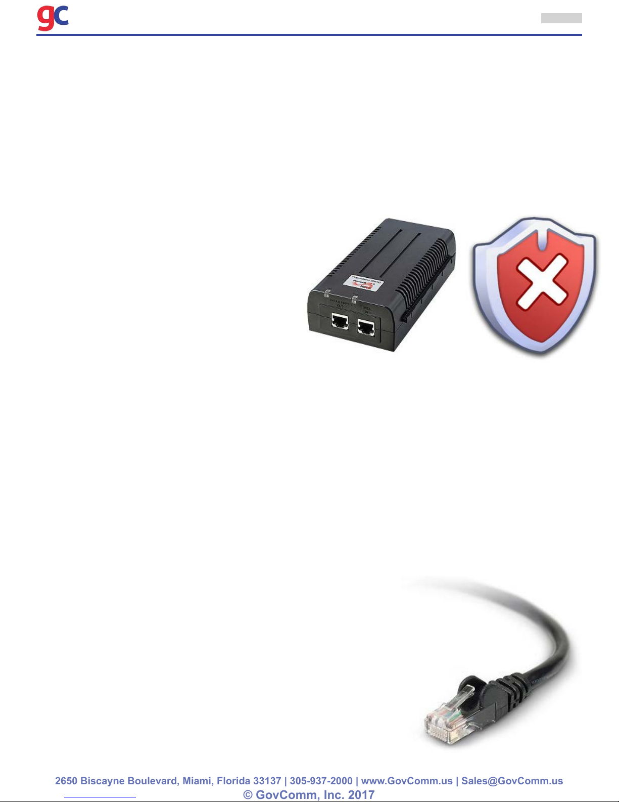
5. Disable Antivirus Software or Firewalls: In
some cases, a computer’s antivirus utility will
conict a camera’s ability to send video, or a
rewall setting may prevent the connection
altogether. While not an acceptable ‘permanent
solution’, sometimes a worthwhile provision
measure is to disable antivirus software or
loosen rewall protections. If the connection
with the camera is achieved at this step, then
a nal conguration of the antivirus software
or rewall can take place that permits proper
operation.
6. Verify Camera Power and connection: If possible, look at the camera to make sure it is powered
up. Most cameras have LED’s that indicate the camera’s power status, and if it is connected to and
transmitting data to the network. Many times these LED’s may be concealed inside the camera’s
housing. If the camera is externally powered (non-PoE) check the power supply if no LED’s are lit.
If it’s a PoE camera and not powered, check to see if it is plugged into a PoE switch or midspan. Verify that
the camera is receiving the proper wattage of PoE power, outdoor cameras with heater/blowers and PTZ
cameras often require High-PoE or PoE+ 30W or 60W of PoE power that is higher than most standard
15W PoE switches provide, often requiring different wattage midspans. Some cameras that require
>15W of power will boot up and connect with 15W, but not transmit images or respond to PTZ commands.
Another pitfall may be the PoE network switch itself. Some PoE switches do not have enough power
to supply 15W to every port and will not supply power to another camera if it is already overloaded.
To troubleshoot, connect the camera into a suitable PoE injector or midspan to see if that is the
problem.
7. Check the Cabling: If the camera’s link and/or activity lights
aren’t blinking, it’s likely a cable. A high frequency of connection
issues center around cabling problems. Basic IT troubleshooting
places a huge emphasis on checking transmission cables. Since
the nal assembly is only as robust as it’s weakest link, checking
data cables for kinks, frays, shorts, and bad terminations is a very
basic troubleshooting step. Cable and patch panel connections
made in a hurry by hand can get crossed wires or connectors
come loose.Sometimes the power wires to a PoE camera in the
cable may be powering the camera up, but the data wires may
be crossed or not connected preventing network connection. To
troubleshoot, use a cable tester to test the cabling or use a known
ITS Camera System - Installation and User Manual
2650 Biscayne Boulevard, Miami, Florida 33137 | 305-937-2000 | www.GovComm.us | Sales@GovComm.us
© GovComm, Inc. 2017
good cable to connect to the camera and see
if it connects. If a patch panel is used, check
the patch cable, that often gets overlooked.
8. Know the password: If there is a ping to the
camera, but can’t connect to it with the VMS,
web browser or discovery tool, it might be
because of an incorrect login or password.
If the defaults don’t work, someone probably
changed them and the user will need to nd
out what was changed to in order to connect.
9. Don’t be a hero, call for help: If the above
steps have been followed and there is still no
connection, visit the manufacturers website for specic model troubleshooting guides and if those
don’t help, call the camera manufacturer’s tech support line. Many times they know “tricks” specic
to their hardware and can remotely connect to the PC via the internet to diagnose. Don’t be afraid to
ask for help, many times technicians waste hours tracking down a problem that the manufacturer’s
help desk representative can x in a few minutes.
10. Factory Default the Camera: Some consider this the most
drastic troubleshooting step to take. Unlike Tip #1 that
restarts the camera, factory defaulting removes all setting and
conguration and returns the device to it’s ‘factory default’
settings. Most IP cameras have a pin hole / reset button on the
back of the device that enables factory defaulting the camera.
Unfortunately, camera operating systems can sometimes become
corrupt, or errors in the conguration can cause a camera to ‘become
lost’. Defaulting a camera takes it back to a xed reference point
where reconguration can begin. However once back to default, the
camera loses all settings and history which may be vital for further
troubleshooting. It may be best to wait until after calling tech support
before trying this step.
10

ITS Camera System - Installation and User Manual
2650 Biscayne Boulevard, Miami, Florida 33137 | 305-937-2000 | www.GovComm.us | Sales@GovComm.us
© GovComm, Inc. 2017
11
1.7 Troubleshooting GovComm ITS Cameras
If a GovComm ITS Camera was installed and there is access to the camera but are experiencing
issues such as: low quality video, image freezing, skipping of frames etc. please follow these troubleshooting steps:
1. If a Moxa HiPOE injector and GovComm PTZ camera are being used make sure to have the injec-
tor congured in 4 pair mode and HiPower. see attached screen shot.
2. Disconnect the camera from the switch and connect to the computer directly to the camera (by-
passing the switch). A crossover cable is not needed, a normally congured category 5 or 6 cable
is sufcient. This test eliminates the switch making sure the problems are not in the switch.
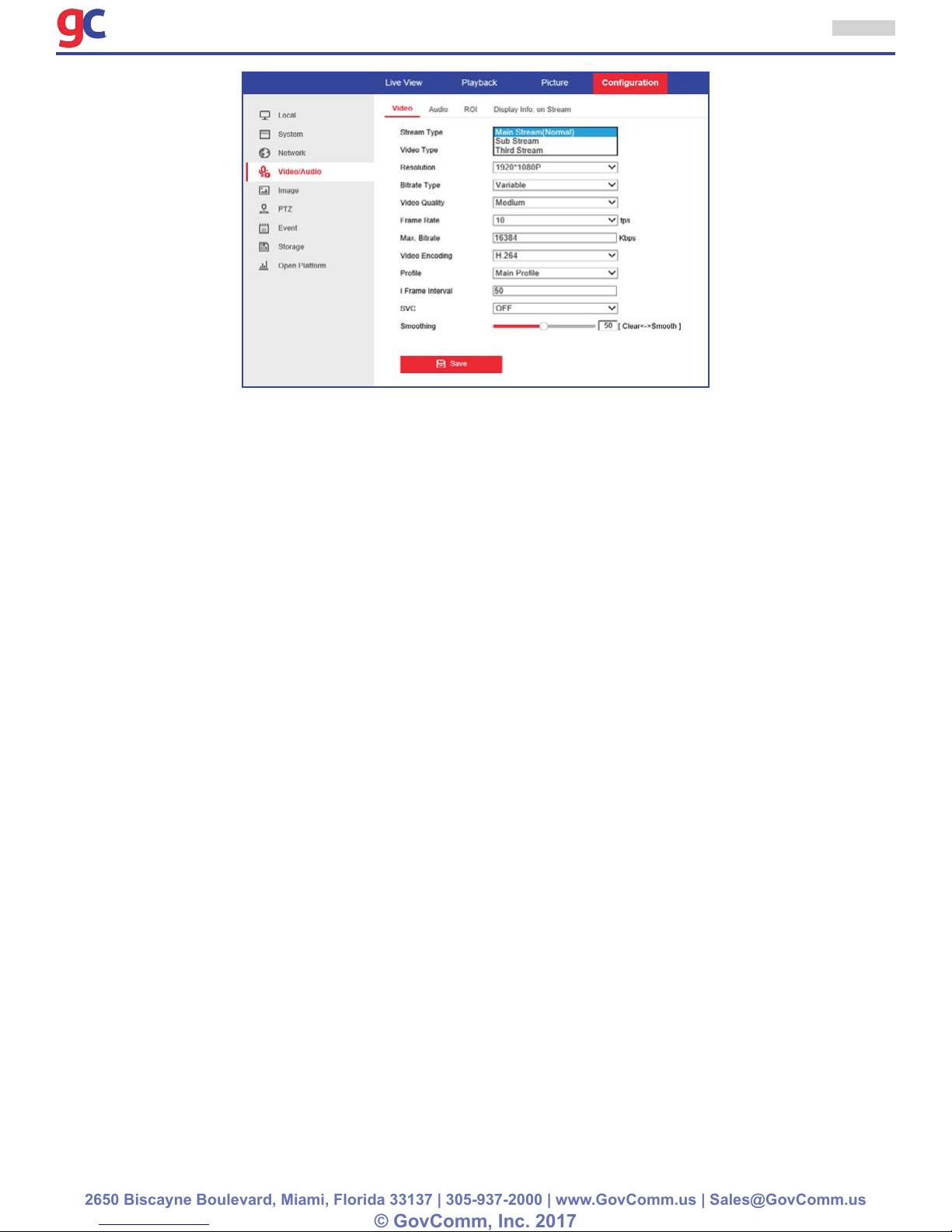
3. If problems still exist, test the bandwidth to the camera by making the following changes on the
camera 1 step at a time while observing how the image quality is affected:
» Lower the resolution
» Lower the frame rate
» Make sure the bit rate is not capped. In order to be able to get a 2 MP at 30 FPS in H.264 at
least 10Mb is needed so the bit rate should be at more than 10000.
4. If there is a direct connection to the camera and the user does not experience problems or have
xed the problem by following recommendations in Item 3, the user needs to look at the switch
conguration.
5. If there is a long cable running (depending on certain conditions) there could be issues such as
freezing, pixelation etc. This is probably because the port on the switch where the camera is
connected is congured to AUTO negotiating. Because of the long cable run, the highest speed
may not be possible to maintain...the switch may be trying to negotiate at a lower speed. This may
result in packet loss and dropping of packages. In this case we recommend changing the conguration from AUTO negotiating to xed speed (10 Mb) so that the switch does not attempt to rene-
gotiate and lose packages. The same settings can also be changed on the camera. 10 Mb should
be sufcient throughput to operate the camera at 2 mp /30 FPS at H.264.
ITS Camera System - Installation and User Manual
2650 Biscayne Boulevard, Miami, Florida 33137 | 305-937-2000 | www.GovComm.us | Sales@GovComm.us
© GovComm, Inc. 2017
12
2.0 PTZ Conguration
2.1 Conguring Initial Position
Purpose:
The initial position is the origin of PTZ coordinates. It can be the factory default initial position. A custom initial position can be manually made.
• Customize an Initial Position:
Steps:
1. Enter the Initial Position Conguration interface:Conguration > PTZ > Initial Position
2. Click the PTZ control buttons to nd a position as the initial position of the dome; the user can also
call a dened preset and set it as the initial position of the dome.
3. Click Set to save the position.
• Call/Delete an Initial Position:
The user can click Call to go back to the initial position. Click Clear to delete the initial position and
restore the factory default initial position.
2.2 Conguring Basic PTZ Parameters
Purpose:
The user can congure the basic PTZ parameters, including proportional pan, preset freezing, preset
speed, etc.
1. Enter the Basic PTZ Parameter Conguration interface: Conguration > PTZ > Basic Settings

ITS Camera System - Installation and User Manual
2650 Biscayne Boulevard, Miami, Florida 33137 | 305-937-2000 | www.GovComm.us | Sales@GovComm.us
© GovComm, Inc. 2017
2. Congure the following settings:
13
• Basic Parameters: Enable/disable proportional pan and preset freezing, set the preset speed,
keyboard control speed, and auto scan speed.
» Proportional Pan: If the user enables this function, the pan/tilt speeds change according to the
amount of zoom. When there is a large amount of zoom, the pan/tilt speed will be slower for
keeping the image from moving too fast on the live view image.
» Preset Freezing: This function enables the live view to switch directly from one scene dened
by a preset to another, without showing the middle areas between these two, to ensure the
surveillance efciency. It can also reduce the use of bandwidth in a digital network system.
Note: Preset freezing function is invalid when calling a pattern.
» Preset Speed: The user can set the speed of a dened preset from 1 to 8.
» Keyboard Control Speed: Dene the speed of PTZ control by a keyboard as Low, Normal or
High.
» Auto Scan Speed:The dome provides 5 scan modes: auto scan, tilt scan, frame scan, random
scan and panorama scan. The scan speed can be set from level 1 to 40.
• PTZ OSD: Set the on-screen display duration of the PTZ status.
» Zoom Status: Set the OSD duration of zooming status as 2 seconds, 5 seconds, 10 seconds,
Always Close or Always Open.
» PT Status: Set the azimuth angle display duration while panning and tilting as 2 seconds, 5
seconds, 10 seconds, Always Close or Always Open.
» Preset Status: Set the preset name display duration while calling the preset as 2 seconds, 5
seconds, 10 seconds, Always Close or Always Open.
» Power-off Memory: The dome can resume its previous PTZ status or actions after it restarted
from a power-off. The user can set the time point of which the dome resumes its PTZ status. The

ITS Camera System - Installation and User Manual
2650 Biscayne Boulevard, Miami, Florida 33137 | 305-937-2000 | www.GovComm.us | Sales@GovComm.us
© GovComm, Inc. 2017
user can set it to resume the status of 30 seconds, 60 seconds, 300 seconds or 600 seconds
before power-off.
3. Click Save to save the settings.
2.3 Conguring PTZ Limit Stops
Purpose:
The dome can be programmed to move within the congurable limit stops (left/right, up/down).
Steps:
1. Enter the Limit Conguration interface: Conguration > PTZ > Limit
14
2. Click the checkbox of Enable Limit and choose the limit type as manual stops or scan stops.
• Manual Stops: When manual limit stops are set, operate the PTZ control panel manually only in the
limited surveillance area.
• Scan Stops: When scan limit stops are set, the random scan, frame scan, auto scan, tilt scan,
panorama scan is performed only in the limited surveillance area.
Note: Manual Stops of Limit Type is prior to Scan Stops. When the user sets these two limit
types at the same time, Manual Stops is valid and Scan Stops is invalid.
3. Click the PTZ control buttons to nd the left/right/up/down limit stops; the user can also call the
dened presets and set them as the limits of the dome.
4. Click Set to save the limits or click Clear to clear the limits.

ITS Camera System - Installation and User Manual
2650 Biscayne Boulevard, Miami, Florida 33137 | 305-937-2000 | www.GovComm.us | Sales@GovComm.us
© GovComm, Inc. 2017
15
2.4 Conguring Scheduled Tasks
Purpose:
Tocongure the network dome to perform a certain action automatically in a user-dened time period.
Steps:
1. Enter the Scheduled Task Settings interface: Conguration > PTZ > Scheduled Tasks
2. Check the checkbox of Enable Scheduled Task.
3. Set the Park Time. Set the park time (a period of inactivity) before the dome starts the scheduled
tasks.
4. Set the schedule and task details.
Steps:
» (1) Choose the day to set the task schedule.
» (2) Click and drag on the open space to create a bar, which represents the time that the scheduled
task will be active. Click on the bar to be able to Input the Start Time and End Time for each task.
» (3) Choose the task type from the drop-down list. The user can choose scan, preset, pattern and
etc.

ITS Camera System - Installation and User Manual
2650 Biscayne Boulevard, Miami, Florida 33137 | 305-937-2000 | www.GovComm.us | Sales@GovComm.us
© GovComm, Inc. 2017
» (4) After inputing the time and preset, click Save to save. The set settings can also be deleted by
clicking Delete.
» (5) After setting the scheduled task, copy the task to other days (Optional) by clicking on the
icon. Check the days that are going to have the same scheduled task and click on OK to
save.
» (6) Click Save to save the settings.
Note: The time of each task can’t be overlapped. Up to 10 tasks can be congured for each
day.
5. Click Save to save the settings.
16
2.5 Conguring Park Actions
Purpose:
This feature allows the dome to start a predened park action (scan, preset, pattern and etc.) automatically
after a period of inactivity (park time).
Note: Scheduled Tasks function is prior to Park Action function. When these two functions
are set at the same time, only the Scheduled Tasks function takes effect.
Steps:
1. Enter the Park Action Settings interface: Conguration > PTZ > Park Action
2. Check the checkbox of Enable Park Action.
3. Set the Park Time as the inactivity time of the dome before it starts the park actions.
4. Choose Action Type the from the drop-down list.
5. Click Save to save the settings.

ITS Camera System - Installation and User Manual
2650 Biscayne Boulevard, Miami, Florida 33137 | 305-937-2000 | www.GovComm.us | Sales@GovComm.us
© GovComm, Inc. 2017
17
2.6 Conguring Privacy Mask
Purpose:
Privacy mask enables the user to cover certain areas on the live video to prevent certain spots in the
surveillance area from being live viewed and recorded.
Steps:
1. Enter the Privacy Mask Settings interface: Conguration > PTZ > Privacy Mask
2. Click the PTZ control buttons to nd the area to set the privacy mask.
3. Click Draw Area; click and drag the mouse in the live video window to draw the area.
4. The user can drag the corners of the red rectangle area to draw a polygon mask.
5. Click Stop Drawing to nish drawing or click Clear All to clear all of the areas set without saving
them.
6. Click Add to save the privacy mask, and it will be listed in the Privacy Mask List Area; the
user can select a mask and click Delete to delete it from the list; the user also denes the color of
the masks.
7. Check the checkbox of Enable Privacy Mask to enable this function.
Note: The user is allowed to draw up to 24 areas on the same image.

ITS Camera System - Installation and User Manual
2650 Biscayne Boulevard, Miami, Florida 33137 | 305-937-2000 | www.GovComm.us | Sales@GovComm.us
© GovComm, Inc. 2017
2.7 Conguring Smart Tracking
Purpose:
The ITS Camera tracks the moving objects automatically after the user congures this function.
Steps:
1. Enter the Smart Tracking Settings interface: Conguration > PTZ > Smart Tracking
18
2. Check the Enable Smart Tracking check box to enable smart tracking function.
3. Click the PTZ buttons to select an object.
4. Click Set Zoom Ratio to set the current zoom ratio as the tracking zoom ratio.
5. Set the tracking duration. The ITS Camera stops tracking when the duration time is up. The duration
ranges from 0 to 300 seconds.
Note:
• Setting the duration to 0 means that there’s no duration when ITS Camera tracks.
• Not all the ITS Camera models support this function. Please take the browser interface of the
actual product product as standard.
2.8 Clearing PTZ Congurations
Purpose:
The user can clear PTZ congurations in this interface, including all presets, patrols, patterns, privacy
masks, PTZ limits and scheduled tasks.
Steps:
1. Enter the Clearing Conguration interface: Conguration > PTZ > Clear Cong
2. Check the checkbox of the items the user wants to clear.
3. Click Save to clear the settings.

ITS Camera System - Installation and User Manual
2650 Biscayne Boulevard, Miami, Florida 33137 | 305-937-2000 | www.GovComm.us | Sales@GovComm.us
© GovComm, Inc. 2017
3.0 ITS Camera Conguration
3.1 Conguring Local Parameters
Note: The local conguration refers to the parameters of the live view and other operations
using the web browser.
Steps:
1. Enter the Local Conguration interface: Conguration > Local
19
2. Congure the following settings:
• Live View Parameters: Set the protocol type, stream type, image size and live view performance.
» Protocol Type: TCP, UDP, MULTICAST and HTTP are selectable.
» TCP: Ensures complete delivery of streaming data and better video quality, yet the real-time
transmission will be affected.
» UDP: Provides real-time audio and video streams.
» HTTP: Allows the same quality as of TCP without setting specic ports for streaming under some
network environments.
» MULTICAST: It’s recommended to select the protocol type to Multicast when using the Multicast
function. For other information about Multicast, refer to Section 6.3.1 Conguring TCP/IP Settings.
» Live View Performance: Set the live view performance to Least Delay, Balanced or Best
Fluency.
Note: Please set Live View Performance as Best Fluency for the high frame rate ITS
Camera.
» Rules: The user can enable or disable the rules of dynamic analysis for motion here.

ITS Camera System - Installation and User Manual
2650 Biscayne Boulevard, Miami, Florida 33137 | 305-937-2000 | www.GovComm.us | Sales@GovComm.us
© GovComm, Inc. 2017
20
• Record File Settings: Set the saving path of the video les.
» Record File Size: Select the packed size of manually recorded and downloaded video les. The
size can be set to 256M, 512M or 1G.
» Save record les to: Set the saving path for the manually recorded video les.
» Save downloaded les to: Set the saving path for the downloaded video les in the Playback
interface.
• Picture and Clip Settings: Set the saving paths of the captured pictures and clipped video les.
» Save snapshots in live view to: Set the saving path of the manually captured pictures in the
Playback interface.
» Save snapshots when playback to: Set the saving path of the captured pictures in the Playback
interface.
» Save clips to: Set the saving path of the clippedvideo les in the Playback interface.
Note: The user can click Browse to change the directory for saving video les, clips and
pictures.
3. Click Save to save the settings.
3.2 Conguring Time Settings
Purpose:
The user can follow the instructions in this section to congure the time which can be displayed on the
video. There are Time Zone, Time Synchronization, Daylight Saving Time(DST) functions for setting
the time. Time Synchronization consists of auto mode by Network Time Protocol(NTP) server and
manual mode.

ITS Camera System - Installation and User Manual
2650 Biscayne Boulevard, Miami, Florida 33137 | 305-937-2000 | www.GovComm.us | Sales@GovComm.us
© GovComm, Inc. 2017
21
To enter the Time Settings interface: Conguration > System > System Settings > Time Settings
• Conguring Time Synchronization by NTP Server
Steps:
» (1) Check the radio button to enable the NTP function.
» (2) Congure the following settings:
Server Address: IP address of NTP server.
NTP Port: Port of NTP server.
Interval: The time interval between the two synchronizing actions by NTP server.It
can be set from 1 to 10080 minutes.
Note: If the ITS Camera is connected to a public network, the user should use a NTP server
that has a time synchronization function, such as the server at the National Time Center
(IP Address: 210.72.145.44). If the ITS Camera is set in a customized network, NTP software
can be used to establish a NTP server for time synchronization.
• Conguring Time Synchronization Manually
Steps:
(1) Check the Manual Time Sync radio button.
(2) Click the calendar icon to set the system time from the pop-up calendar.
(3) Click Save to save the settings.
Note: The user can alsocheck the Sync with local time checkbox to synchronize the time of
the ITS Camera with the time of the computer.
• Select the Time Zone
Purpose:
When the ITS Camera is taken to another time zone, the user can use the Time Zone function to adjust
the time. The time will be adjusted according to the original time and the time difference between the
two time zones.

ITS Camera System - Installation and User Manual
2650 Biscayne Boulevard, Miami, Florida 33137 | 305-937-2000 | www.GovComm.us | Sales@GovComm.us
© GovComm, Inc. 2017
22
From the Time Zone drop-down menu, select the Time Zone in which the ITS Camera locates.
• Conguring Daylight Saving Time (summer time)
Purpose:
If there is the habit of adjusting clocks forward in the country in certain time period of a year, the user
can turn this function on. The time will be adjusted automatically when the Daylight Saving Time(DST)
comes.
Steps:
(1) Enter the DST interface by Conguration > System > System Settings > DST
(2) Check Enable DST to enable the DST function.
(3) Set the date of the DST period.
(4) Click Save to save the settings.
3.3 Conguring Network Settings
3.3.1 Conguring TCP/IP Settings
Purpose:
TCP/IP settings must be properly congured before the user operates the ITS Camera over network.
IPv4 and IPv6 are both supported.
Steps:
1. Enter TCP/IP Settings interface: Conguration > Network > Basic Settings >TCP/IP

ITS Camera System - Installation and User Manual
2650 Biscayne Boulevard, Miami, Florida 33137 | 305-937-2000 | www.GovComm.us | Sales@GovComm.us
© GovComm, Inc. 2017
23
2. Congure the NIC settings, including the IPv4(IPv6) Address, IPv4(IPv6) Subnet Mask and
IPv4(IPv6) Default Gateway.
3. Click Save to save the above settings.
Note:
• If the DHCP server is available, the user can check DHCP to automatically obtain an IP address
and other network settings from that server.
• The valid value range of Maximum Transmission Unit(MTU) is 500 ~ 9676. The default value is
1500.
• The Multicast sends a stream to the multicast group address and allows multiple clients to
acquire the stream at the same time by requesting a copy from the multicast group address.
Before utilizing this function, the user has to enable the Multicast function of the router and
congure the gateway of the network ITS Camera.
• If the DNS server settings are required for some applications (e.g., sending email), the user
should properly congure the Preferred DNS Server and Alternate DNS server.
Note: The router must support the route advertisement function if the user selects Route
Advertisement as the IPv6 mode.
3.3.2 Conguring Port Settings
Purpose:
If there is a router and the user wants to access the ITS Camera through Wide Area Network (WAN),
the user needs to forward the 3 ports for the ITS Camera.
Steps:
1. Enter the Port Settings interface: Conguration > Network > Port

ITS Camera System - Installation and User Manual
2650 Biscayne Boulevard, Miami, Florida 33137 | 305-937-2000 | www.GovComm.us | Sales@GovComm.us
© GovComm, Inc. 2017
24
2. Set the HTTP port, RTSP port and port of the ITS Camera.
» HTTP Port: The default port number is 80.
» RTSP Port: The default port number is 554.
» HTTPS Port: The default port number is 443.
» SDK Port: The default port number is 8000.
3. Click Save to save the settings.
3.3.3 Conguring PPPoE Settings
Purpose:
If the user has no router but only a modem, the user can use Point-to-Point Protocol over Ethernet
(PPPoE) function.
Steps:
1. Enter the PPPoE Settings interface: Conguration > Network > PPPoE
2. Check the Enable PPPoE checkbox to enable this feature.
3. Enter User Name, Password, and Conrm password for PPPoE access.
Note: The User Name and Password should be assigned by the ISP.
4. Click Save to saveand exit the interface.
3.3.4 Conguring DDNS Settings
Purpose:
If the ITS Canera is set to use PPPoE as its default network connection, the user can use the Dynamic
DNS (DDNS) for network access.
Before starting:
Registration on the DDNS server is required before conguring the DDNS settings of the ITS Camera.
Steps:
1. Enter the DDNS Settings interface: Conguration > Network > DDNS

ITS Camera System - Installation and User Manual
2650 Biscayne Boulevard, Miami, Florida 33137 | 305-937-2000 | www.GovComm.us | Sales@GovComm.us
© GovComm, Inc. 2017
25
2. Check the Enable DDNS checkbox to enable this feature.
3. Select DDNS Type. Three DDNS types are selectable: IPServer, HiDDNS, NO-IP and DynDNS.
• DynDNS:
Steps:
(1) Enter Server Address of DynDNS (e.g. members.dyndns.org).
(2) In the Domain text eld, enter the domain name obtained from the DynDNS website.
(3) Enter the Port of DynDNS server.
(4) Enter the User Name and Password registered on the DynDNS website.
(5) Click Save to save the settings.
• IP Server:
Steps:
(1) Enter the Server Address of the IP Server.
(2) Click Save to save the settings.
Note: The Server Address should be entered with the static IP address of the computer that
runs the IP Server software. For the IP Server, apply a static IP, subnet mask, gateway
and preferred DNS from the ISP.

ITS Camera System - Installation and User Manual
2650 Biscayne Boulevard, Miami, Florida 33137 | 305-937-2000 | www.GovComm.us | Sales@GovComm.us
© GovComm, Inc. 2017
26
• HiDDNS:
Steps:
(1) Enter the Server Address: www.hik-online.com.
(2) Enter the Domain name of the camera. The domain is the same with the device alias in
the HiDDNS server.
(3) Click Save to save the settings.
• NO-IP:
Steps:
(1) Enter Server Address of NO-IP.
(2) In the Domain text eld, enter the domain name obtained from the NO-IP website.
(3) Enter the Port of NO-IP server.
(4) Enter the User Name and Password registered on the NO-IP website.
(5) Click Save to save the settings.
3.3.5 Conguring SNMP Settings
Purpose:
The user can use SNMP to get ITS Camera status and parameters related information.
Before starting:
Before setting the SNMP, please use the SNMP software and manage to receive the ITS Camera
information via SNMP port. By setting the Trap Address, the ITS Camera can send the alarm event
and exception messages to the surveillance center.
Note: The SNMP version selected should be the same as that of the SNMP software.
Step:
1. Enter the SNMP Settings interface: Conguration > Advanced Conguration > Network > SNMP
2. Check the corresponding version checkbox (Enable SNMP SNMPv1, Enable SNMP v2c, Enable
SNMPv3) to enable the feature.
3. Congure the SNMP Settings.
Note: The conguration of the SNMP software should be the same as the settings
congured here.
4. Click Save to save and nish the settings.

ITS Camera System - Installation and User Manual
2650 Biscayne Boulevard, Miami, Florida 33137 | 305-937-2000 | www.GovComm.us | Sales@GovComm.us
© GovComm, Inc. 2017
27
3.3.6 Conguring 802.1X Settings
Purpose:
The ITS Camera supports IEEE 802.1X standard.
IEEE 802.1X is a port-based network access control. It enhances the security level of the LAN. When
devices connect to this network with IEEE 802.1X standard, the authentication is needed. If the
authentication fails, the devices don’t connect to the network.
The protected LAN with 802.1X standard is shown as follows:
• Before connecting the Network Camera to the protected LAN, please apply a digital certicate from
a Certicate Authority.
• The network camera requests access to the protected LAN via the authenticator (a switch).
• The switch forwards the identity and password to the authentication server (Radius server).
• The switch forwards the certicate of authentication server to the network camera.
• If all the information is validated, the switch allows the network access to the protected network.
Steps:
1. Connect the network camera to the PC directly with a network cable.
2. Enter the 802.1X Settings interface: Conguration > Network > Advanced Settings > 802.1X

ITS Camera System - Installation and User Manual
2650 Biscayne Boulevard, Miami, Florida 33137 | 305-937-2000 | www.GovComm.us | Sales@GovComm.us
© GovComm, Inc. 2017
28
3. Check the Enable IEEE 802.1X checkbox to enable it.
4. Congure the 802.1X settings, including user name and password.
Note: The EAP-MD5 version must be identical with that of the router or the switch.
5. Enter the user name and password (issued by the CA) to access the server.
6. Click Save to nish the settings.
Note: The camera reboots when the user saves the settings.
7. After the conguration, connect the camera to the protected network.
3.3.7 Conguring QoS Settings
Purpose:
QoS (Quality of Service) can help solve the network delay and network congestion by conguring the
priority of data sending.
Steps:
1. Enter the QoS Settings interface: Conguration > Network >Advanced Settings > QoS
2. Congure the QoS settings, including video / audio DSCP, event / alarm DSCP and Management DSCP.
The valid DSCP value ranges from 0 to 63. The DSCP value is bigger, the priority is higher.
3. Click Save to save the settings.
Note:
• Make sure to enable the QoS function of the network device (such as a router).
• It will ask for a reboot for the settings to take effect.
3.3.8 Conguring FTP Settings
Purpose:
The user can set a FTP server and congure the following parameters for uploading captured pictures.
Steps:
1. Enter the FTP Settings interface: Conguration > Network > Advanced Settings > FTP
2. Congure the FTP settings, including server address, port, user name, password, directory and
upload type.
• Setting the directory in FTP server for saving les:
In the Directory Structure eld, the user can select the root directory, parent directory and child
directory.

ITS Camera System - Installation and User Manual
2650 Biscayne Boulevard, Miami, Florida 33137 | 305-937-2000 | www.GovComm.us | Sales@GovComm.us
© GovComm, Inc. 2017
» Root Directory: The les will be saved in the root of FTP server.
» Parent Directory: The les will be saved in a folder in the FTP server.
29
» Child Directory: It is a sub-folder which can be created in the parent directory. The les will be
saved in a sub-folder in FTP server.
• Upload Type: To enable uploading the captured picture to the FTP server.
3. Click Save to save the settings.
Note: If the user wants to upload the captured pictures to FTP server, the user also has to
enable the continuous snapshot or event-triggered snapshot in Snapshot interface.
3.3.9 Conguring NAT Settings
• UPnP
Universal Plug and Play (UPnP) is a networking architecture that provides compatibility among networking equipment, software and other hardware devices. With the UPnP function enabled, the user
doesn’t need to congure the port mapping for each port, and the camera is connected to the Wide
Area Network via the router.
Steps:
1. Enter the UPnP settings interface: Conguration >Network> Basic Settings > NAT
2. Check the Enable UPnP checkbox
3. Add a Friendly Name.

ITS Camera System - Installation and User Manual
2650 Biscayne Boulevard, Miami, Florida 33137 | 305-937-2000 | www.GovComm.us | Sales@GovComm.us
© GovComm, Inc. 2017
30
4. Click Save to save the settings.
• Port Maping
Steps:
1. Check the Enable Port Mapping checkbox
2. Select the Port Mapping Mode as Auto or Manual.
3. If in Manual mode, the user can check the checkbox of HTTP, RTSP or SDK port according to the
demand.
4. Click Save to save the settings.
3.3.10 Conguring Email Settings
Purpose:
The system can be congured to send an Email notication to all designated receivers if an alarm event
is detected, e.g., motion detection event, video loss, tamper-proof, etc.
Before starting:
Please congure the DNS Server settings under Conguration > Network > Basic Settings > TCP/
IP before using the Email function.
Steps:
1. Enter the Email Settings interface: Conguration > Network > Email

ITS Camera System - Installation and User Manual
2650 Biscayne Boulevard, Miami, Florida 33137 | 305-937-2000 | www.GovComm.us | Sales@GovComm.us
© GovComm, Inc. 2017
31
2. Congure the following settings:
» Sender: The name of the email sender.
» Sender’s Address: The email address of the sender.
» SMTP Server: The SMTP Server IP address or host name (e.g.,smtp.263xmail.com).
» SMTP Port: The SMTP port. The default TCP/IP port for SMTP is 25. Enable SSL: Check the
checkbox to enable SSL if it is required by the SMTP server.
» Attached Image: Check the checkbox of Attached Image to send emails with attached alarm
images.
» Interval: The interval refers to the time between two actions of sending attached pictures.
» Authentication (optional): If the email server requires authentication, check this checkbox to
use authentication to log in to this server and enter the login user name and password.
» Receiver: Select the receiver to which the email is sent. Up to 2 receivers can be congured.
» Receiver: The name of the user to be notied.
» Receiver’s Address: The email address of user to be notied.
3. Click Save to save the settings.
3.4 Conguring Video and Audio Settings
3.4.1 Conguring Video Settings
Steps:
1. Enter the Video Settings interface: Conguration > Video / Audio > Video

ITS Camera System - Installation and User Manual
2650 Biscayne Boulevard, Miami, Florida 33137 | 305-937-2000 | www.GovComm.us | Sales@GovComm.us
© GovComm, Inc. 2017
32
2. Select the Stream Type of the ITS Camera to main stream (normal), sub-stream or third stream.The
main stream is usually for recording and live viewing with good bandwidth , and the sub-stream can
be used for live viewing when the bandwidth is limited. Refer to the Section 3.1 Conguring Local
Parameters for switching the main stream and sub-stream for live viewing.
3. The user can customize the following parameters for the selected main stream, sub-stream or
third stream:
Video Type:
Select the stream type to video stream, or video & audio composite stream. The audio signal will
be recorded only when the Video Type is Video & Audio.
Resolution:
Select the resolution of the video output.
Bitrate Type: Select the bitrate type to constant or variable.
Video Quality:
When bitrate type is selected as Variable, 6 levels of video quality are selectable.
Frame Rate:
The frame rate is to describe the frequency at which the video stream is updated and it is
measured by frames per second (fps). A higher frame rate is advantageous when there is
movement in the video stream, as it maintains image quality throughout.
Max. Bitrate:
Set the max. bitrate to 32~16384 Kbps. The higher value corresponds to the higher video quality,
but the higher bandwidth is required.
Video Encoding:
The Video Encoding standard can be set to H.264 or MJPEG.
Prole:
The user can set the prole level to High Prole, Main Prole or Basic Prole.
I-Frame Interval:
Set the I-Frame interval from 1 to 400.
4. Click Save to save the settings.

ITS Camera System - Installation and User Manual
2650 Biscayne Boulevard, Miami, Florida 33137 | 305-937-2000 | www.GovComm.us | Sales@GovComm.us
© GovComm, Inc. 2017
3.4.2 Conguring Audio Settings
Steps:
1. Enter the Audio Settings interface: Conguration > Video / Audio > Audio
2. Congure the following settings.
Audio Encoding: G.722.1, G.711ulaw, G.711alaw, MP2L2, G.726 and PCM.
33
3. Click Save to save the settings.
3.4.3 Conguring ROI Settings
Before starting:
ROI (Region of Interest) encoding is used to enhance the quality of images which are specied in
advance.
Stream Type:
The user can set the ROI function for main stream, sub stream or third stream. Select a stream type
and then congure the ROI settings.
• Fixed Region: Draw several xed areas and apply the ROI function on them.
Steps:
1. Select a Region No.
2. Check the check box of Enable under Fixed Region.
3. Click Draw Area and draw a red frame in the live view image.
4. Adjust the Enhance the level from 1 to 6. The higher the value, the better image quality in the red
frame.
5. Enter a Region Name and click Save to save the settings.

ITS Camera System - Installation and User Manual
2650 Biscayne Boulevard, Miami, Florida 33137 | 305-937-2000 | www.GovComm.us | Sales@GovComm.us
© GovComm, Inc. 2017
34
• Dynamic Tracking: The center area of the tracking scene is specied ROI function by default.
When the ITS Camera starts smart tracking, the quality in the image center is enhanced.
Steps:
1. Check the check box of Enable under Dynamic Tracking.
2. Adjust the Enhance the level from 1 to 6. The higher the value, the better the ROI quality.
3. Click Save to save the settings.
3.5 Conguring Image Settings
3.5.1 Conguring Display Settings
Purpose:
The user can set the image quality of the ITS Camera, including brightness, contrast, saturation,
sharpness, etc.
Note:
• The parameters in Display Settings interface vary depending on the models of ITS Camera.
• The user can double click the live view to enter full screen mode and double click it again to exit.
Steps:
1. Enter the Display Settings interface: Conguration > Image> Display Settings

ITS Camera System - Installation and User Manual
2650 Biscayne Boulevard, Miami, Florida 33137 | 305-937-2000 | www.GovComm.us | Sales@GovComm.us
© GovComm, Inc. 2017
2. Set the image parameters of the ITS Camera.
35
• Image Adjustment
» Brightness
This feature is used to adjust brightness of the image. The value ranges from 0 to 100.
» Contrast
This feature enhances the difference in color and light between parts of an image. The
value ranges from 0 to 100.
» Saturation
This feature is used to adjust color saturation of the image. The value ranges from 0 to 100.
» Sharpness
Sharpness function enhances the detail of the image by sharpening the edges in the image. The
value ranges from 0 to 100.
Note: This function varies depending on the models of the ITS Camera.

2650 Biscayne Boulevard, Miami, Florida 33137 | 305-937-2000 | www.GovComm.us | Sales@GovComm.us
© GovComm, Inc. 2017
• Exposure Settings
» Exposure Mode
The Exposure Mode can be set to Auto, Iris Priority, Shutter Priority, Manual.
» Auto:
The iris, shutter and gain values will be adjusted automatically according to the brightness of the
environment.
» Iris Priority:
The value of iris needs to be adjusted manually. The shutter and gain values will be adjusted
automatically according to the brightness of the environment.
ITS Camera System - Installation and User Manual
36
» Shutter Priority: The value of shutter needs to be adjusted manually. The iris and gain values
will be adjusted automatically according to the brightness of the environment.
» Gain Priority:
The value of gain needs to be adjusted manually. The shutter and iris values will be adjusted
automatically according to the brightness of the environment.

ITS Camera System - Installation and User Manual
2650 Biscayne Boulevard, Miami, Florida 33137 | 305-937-2000 | www.GovComm.us | Sales@GovComm.us
© GovComm, Inc. 2017
» Manual:
In Manual mode, the user can adjust the values of Gain, Shutter, Iris manually.
Note: This function varies depending on the models of the ITS Camera.
• Focus
» Focus Mode
The Focus Mode can be set to Auto, Manual, Semi-auto.
» Auto:
The ITS Camera focuses automatically at any time according to objects in the scene.
» Semi-auto:
The ITS Camera focuses automatically only once after panning, tilting and zooming.
37
» Manual:
In Manual mode, the user needs to use on the control panel to focus manually.
» Min. Focus Distance
This function is used to limit the minimum focus distance. The value can be set to 1.5m, 3m,
6m, 10cm and 50cm.
Note: The minimum focus value varies depending on the models of the ITS Camera.
• Day/Night Switch
The Day/Night Switch mode can be set to Auto, Day and Night.
» Auto:
In Auto mode, the day mode and night mode can switch automatically according to the light
condition of environment. The switching sensitivity can be set to Low, Normal, High.
» Day:
In Day mode, the ITS Camera displays color image. It is used for normal lighting
conditions.
» Night:
In Night mode, the image is black and white. Night mode can increase the sensitivity in low
light conditions.

ITS Camera System - Installation and User Manual
2650 Biscayne Boulevard, Miami, Florida 33137 | 305-937-2000 | www.GovComm.us | Sales@GovComm.us
© GovComm, Inc. 2017
• Backlight Settings
» BLC
If there’s a bright backlight, the subject in front of the backlight appears silhouetted or dark.
Enabling BLC(back light compensation) function can correct the exposure of the subject. But
the backlight environment is washed out to white.
» WDR (Wde Dynamic Range)
The wide dynamic range (WDR) function helps the camera provide clear images even
under back light circumstances. When there are both very bright and very dark areas
simultaneously in the eld of view, WDR balances the brightness level of the whole image and
provide clear images with details.
The user can enable or disable the WDR function The wide dynamic level ranges from 0 to
100.
38
Note: This function varies depending on the models of the ITS Camera.
» HLC
HLC (High Light Compensation) makes the camera identify and suppress the strong
light sources that usually are across a scene. This makes it possible to see the detail of the
image that would normally be hidden.
• White Balance
The White Balance mode can be set to Auto, MWB, Outdoor, Indoor, Fluorescent Lamp, Sodium
Lamp and Auto-Track.
» Auto:
In Auto mode, the camera retains color balance automatically according to the current color
temperature.
» Manual White Balance:
In MWB mode, the user can adjust the color temperature manually to meet special
requirements.
» Outdoor
The user can select this mode when the ITS Camera is installed in outdoor environment.

ITS Camera System - Installation and User Manual
2650 Biscayne Boulevard, Miami, Florida 33137 | 305-937-2000 | www.GovComm.us | Sales@GovComm.us
© GovComm, Inc. 2017
» Indoor
The user can select this mode when the ITS Camera is installed in indoor environment.
» Fluorescent Lamp
The user can select this mode when there are uorescent lamps installed near the ITS Camera.
» Sodium Lamp
The user can select this mode when there are sodium lamps installed near the ITS Camera.
» Auto-Track
In Auto-Track mode, white balance is continuously being adjusted in real-time according to the
color temperature of the scene illumination.
Note: This function varies depending on the models of the ITS Camera.
39
• Image Enhancement
» 3D Digital Noise Reduction
The user can enable or disable the 3D Digital Noise Reduction function. The level ranges from
0 to 100.
» De-fog Mode
When there is fog in the image, the user can enable this function to get clear image.
• Video Adjustment
» Video Standard
The user can set the Video Standard to 50hz(PAL) or 60hz(NTSC) according to the video
system in the user country.
Note: This function varies depending on the models of the ITS Camera.
» Mirror
If the user turns the MIRROR function on, the image will be ipped. It is like the image in the
mirror. The ip direction can be set to OFF, LEFT/RIGHT, UP/DOWN or CENTER.
Note: This function varies depending on the models of the ITS Camera.

ITS Camera System - Installation and User Manual
2650 Biscayne Boulevard, Miami, Florida 33137 | 305-937-2000 | www.GovComm.us | Sales@GovComm.us
© GovComm, Inc. 2017
40
Lens Initialization
The lens operates the movements for initialization when the user checks the check box of Lens Initialization.
Zoom Limit
The user can set Zoom Limit value to limit the maximum value of zooming. The value can be set to
20, 40, 80, 160 and 320.
Note: This function varies depending on the models of the ITS Camera.
Local Output
The user can select the output mode to ON or OFF.
3.5.2 Conguring OSD Settings
Purpose:
The ITS Camera supports following on screen displays:
Zoom: Identies the amount of magnication.
Direction: Displays panning and tilting direction, with the format of PXXX TXXX. The XXX
following P indicates the degrees in pan direction, while the XXX following T indicates the degrees in
tilt position.
Time: Supports for time display.
Preset Title: Identies preset being called.
Camera Name: Identies the name of ITS Camera.
The user can customize the on screen display of time.
Steps:
• 1. Enter the OSD Settings interface: Conguration > Image > OSD Settings

ITS Camera System - Installation and User Manual
2650 Biscayne Boulevard, Miami, Florida 33137 | 305-937-2000 | www.GovComm.us | Sales@GovComm.us
© GovComm, Inc. 2017
41
• 2. Check the corresponding checkbox to select the display of the ITS Camera name, date or week if
required.
• 3. Edit the ITS Camera name in the text eld of Camera Name.
• 4. Select from the drop-down list to set the time format, date format and display mode.
• 5. The user can use the mouse to click and drag the text frame IPDome2 in the live view window to
adjust the OSD position.
• 6. Click Save to activate above settings.
3.5.3 Conguring Text Overlay Settings
Purpose:
The user can customize the text overlay.
Steps:
1. Enter the Text Overlay Settings interface: Conguration > Image > OSD Settings
2. Check the checkbox in front of textbox to enable the on-screen display.
3. Input the characters in the textbox.
4. Use the mouse to click and drag the red text frame Text in the live view window to adjust the text
overlay position.
5. Click Save.
Note: There are up to 8 text overlays congurable.

ITS Camera System - Installation and User Manual
2650 Biscayne Boulevard, Miami, Florida 33137 | 305-937-2000 | www.GovComm.us | Sales@GovComm.us
© GovComm, Inc. 2017
42
3.6 Conguring and Handling Alarms
Purpose:
This section explains how to congure the network ITS Camera to respond to alarm events, including
motion detection, external alarm input, video loss, tamper-proof and exception. These events can
trigger the alarm actions, such as Notify Surveillance Center, Send Email, Trigger Alarm Output, etc.
For example, when an external alarm is triggered, the network ITS Camera sends a notication to an
e-mail address.
3.6.1 Conguring Motion Detection
Purpose:
Motion detection is a feature which can trigger alarm actions and actions of recording videos when
the motion occurred in the surveillance scene.
Steps:
1. Set the Motion Detection Area.
Steps:
» (1) Enter the motion detection settings interface: Conguration > Events > Basic Event >
Motion Detection
» (2) Check the checkbox of Enable Motion Detection.
» (3) Click Draw Area. Click and drag the mouse on the live video image to draw a motion
detection area.
Note: The user can draw up to 8 motion detection areas on the same image.
» (4) Click Stop Drawing to nish drawing.
Note: The user can click Clear All to clear all of the areas.
» (5) Move the slider to set the diversity of the detection.

ITS Camera System - Installation and User Manual
2650 Biscayne Boulevard, Miami, Florida 33137 | 305-937-2000 | www.GovComm.us | Sales@GovComm.us
© GovComm, Inc. 2017
2. Set the Arming Schedule for Motion Detection.
Steps:
» (1) Click on Arming Schedule tab.
43
» (2) Click and drag the slider next to the days to set the time for the Arming Schedule. The user can
also click on the bar to open the settings for the time and it can be inputted.
» (3) After setting the arming schedule, click on to open the Copy to pop-up with lets the user
select days to copy the settings for. Click OK when done.(Optional).
» (4) Click Save to save the settings.
Note:
The time of each period can’t be overlapped. Up to 4 periods can be congured for each
day.

ITS Camera System - Installation and User Manual
2650 Biscayne Boulevard, Miami, Florida 33137 | 305-937-2000 | www.GovComm.us | Sales@GovComm.us
© GovComm, Inc. 2017
44
3. Set the Alarm Actions for Motion Detection.
Purpose:
The user can specify the linkage method when an event occurs. The following contents are about
how to congure the different types of linkage method.
Check the checkbox to select the linkage method. Notify surveillance center, send email, upload to
FTP, trigger channel and trigger alarm output are selectable.
• Send Email
Send an email with alarm information to a user or users when an event occurs.
Note: To send the Email when an event occurs, refer to Section 3.3.10 Conguring Email
Settings to set the Email parameters.
• Notify Surveillance Center
Send an exception or alarm signal to remote management software when an event occurs.
• Upload to FTP
Capture the image when an alarm is triggered and upload the picture to a FTP server.
Note: A FTP server is needed and to set FTP parameters rst. Refer to Section 3.3.8
Conguring FTP Settings for setting FTP parameters.
• Trigger Alarm Output
Trigger one or more external alarm outputs when an event occurs.
Note: To trigger an alarm output when an event occurs, please refer to Section 3.6.5
Conguring Alarm Output to set the alarm output parameters.
• Trigger Channel
Record a video when an event occurs.
Note: The user has to set the recording schedule to realize this function.
3.6.2 Conguring Video Loss Alarm
Steps:
1. Enter the Video Loss Setting interface: Conguration > Events > Basic Event >Video Loss
2. Check the Enable checkbox to enable the video loss detection.
3. The arming schedule conguration is the same as the setting of the arming schedule for motion
detection. Refer to Step 2 Set the Arming Schedule for Motion Detection in Section 3.6.1.

ITS Camera System - Installation and User Manual
2650 Biscayne Boulevard, Miami, Florida 33137 | 305-937-2000 | www.GovComm.us | Sales@GovComm.us
© GovComm, Inc. 2017
45
4. Check the checkbox to select the linkage method taken for the video loss alarm. Notify surveillance
center, send email and trigger alarm output are selectable. Please Step 3 Set the Alarm Actions
for Motion Detection in Section 3.6.1.
5. Click Save to save the settings.
3.6.3 Conguring Tamper-proof Alarm
Purpose:
The user can congure the ITS Camera to trigger the alarm actions when the lens is covered.
Steps:
1. Enter the Tamper-proof Settings interface: Conguration > Events > Basic Event > Tamper-proof
2. Check Enable Tamper-proof checkbox to enable the tamper-proof detection.
3. Set the tamper-proof area. Refer to Step 1 Set the Motion Detection Area in Section 3.6.1
Conguring Motion Detection.

ITS Camera System - Installation and User Manual
2650 Biscayne Boulevard, Miami, Florida 33137 | 305-937-2000 | www.GovComm.us | Sales@GovComm.us
© GovComm, Inc. 2017
46
4. The arming schedule conguration is the same as the setting of the arming schedule for motion
detection. Refer to Step 2 Set the Arming Schedule for Motion Detection in Section 3.6.1
Conguring Motion Detection.
5. Check the checkbox to select the linkage method taken for the tamper-proof. Notify surveillance
center, send email and trigger alarm output are selectable. Please refer to Step 3 Set the Alarm
Actions for Motion Detection in Section 3.6.1 Conguring Motion Detection.
6. Click Save to save the settings.

ITS Camera System - Installation and User Manual
2650 Biscayne Boulevard, Miami, Florida 33137 | 305-937-2000 | www.GovComm.us | Sales@GovComm.us
© GovComm, Inc. 2017
47
3.6.4 Conguring External Alarm Input
Steps:
1. Enter the Alarm Input Settings interface: Conguration > Events >Basic Event > Alarm Input:
2. Choose the alarm input No. and the Alarm Type. The alarm type can be NO (Normally Open) and
NC (Normally Closed).
3. Edit the name in to set a name for the alarm input (optional).
4. Click Edit to set the arming schedule for the alarm input. Refer to Step 2 Set the Arming
Schedule for Motion Detection in Section 3.6.1 Conguring Motion Detection.
5. Check the checkbox to select the linkage method taken for the alarm input. Refer to Step 3 Set
the Alarm Actions for Motion Detection in Section 3.6.1 Conguring Motion Detection.
6. The user can also choose the PTZ linking for the alarm input. Check the relative checkbox and
select the No. to enable Preset Calling, Patrol Calling or Pattern Calling.
7. The user can copy the settings to other alarm inputs.
8. Click Save to save the settings.

ITS Camera System - Installation and User Manual
2650 Biscayne Boulevard, Miami, Florida 33137 | 305-937-2000 | www.GovComm.us | Sales@GovComm.us
© GovComm, Inc. 2017
48
3.6.5 Conguring Alarm Output
Steps:
1. Enter the Alarm Output Settings interface: Conguration> Events > Basic Event >Alarm Output
2. Select one alarm output channel in the Alarm Output drop-down list.
3. Set a name in Alarm Name for the alarm output (optional).
4. The Delay time can be set to 5sec, 10sec, 30sec, 1min, 2min, 5min, 10min or Manual. The delay
time refers to the time duration that the alarm output remains in effect after alarm occurs.
5. Click Edit to enter the Edit Schedule T ime interface. The time schedule conguration is the same as
the settings of the arming schedule for motion detection. Refer to Step 2 Set the Arming Schedule
for Motion Detection in Section 3.6.1 Conguring Motion Detection.
6. The user can copy the settings to other alarm outputs.
7. Click Save to save the settings.

ITS Camera System - Installation and User Manual
2650 Biscayne Boulevard, Miami, Florida 33137 | 305-937-2000 | www.GovComm.us | Sales@GovComm.us
© GovComm, Inc. 2017
49
3.6.6 Handling Exception
The exception type can be HDD full, HDD error, network disconnected, IP address conicted
and illegal login to the ITS Cameras.
Steps:
1. Enter the Exception Settings interface: Conguration > Events > Exception
2. Check the checkbox to set the actions taken for the Exception alarm. Refer to Step 3 Set the
Alarm Actions Taken for Motion Detection in Section 3.6.1 Conguring Motion Detection.
3. Click Save to save the settings.
 Loading...