

Page 1
Installation, Operation,
and Maintenance Manual
XHD
Page 2

Page 3

Table of Contents
Introduction and Safety .......................................................................................................... 4
Introduction ............................................................................................................................. 4
Safety ...................................................................................................................................... 4
Safety terminology and symbols ........................................................................................... 4
Environmental safety ............................................................................................................ 5
User safety ........................................................................................................................... 6
Safety regulations for Ex-approved products in potentially explosive atmospheres ............. 7
Product approval standards .................................................................................................... 9
Product warranty ................................................................................................................... 10
Transportation and Storage ................................................................................................. 11
Inspect the delivery ............................................................................................................... 11
Inspect the package ........................................................................................................... 11
Inspect the unit ................................................................................................................... 11
Transportation guidelines ...................................................................................................... 11
Pump handling ................................................................................................................... 11
Lifting methods ................................................................................................................... 11
Storage guidelines ................................................................................................................ 14
Pump storage requirements .................................................................................................. 14
Frostproofing ......................................................................................................................... 14
Table of Contents
Product Description .............................................................................................................. 15
General description ............................................................................................................... 15
General description i-ALERT™ Condition Monitor ................................................................ 17
Nameplate information .......................................................................................................... 18
Installation ............................................................................................................................. 21
Preinstallation ....................................................................................................................... 21
Pump location guidelines .................................................................................................... 21
Foundation requirements ................................................................................................... 21
Baseplate-mounting procedures ........................................................................................... 22
Prepare the baseplate for mounting ................................................................................... 22
Install the baseplate using shims or wedges ...................................................................... 23
Install the baseplate using jackscrews ................................................................................ 24
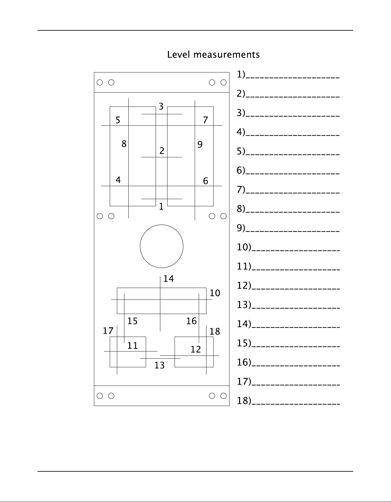
Direct-coupled baseplate-leveling worksheet ..................................................................... 26
Install pump, driver, and v-belt drive ..................................................................................... 27
Install and align the sheaves .............................................................................................. 27
Install and tension the belt .................................................................................................. 27
Install the pump, driver, and coupling .................................................................................... 28
Pump-to-driver alignment ...................................................................................................... 28
Alignment checks ............................................................................................................... 29
Permitted indicator values for alignment checks ................................................................ 29
Alignment measurement guidelines ................................................................................... 30
Attach the dial indicators for alignment ............................................................................... 30
Pump-to-driver alignment instructions ................................................................................ 30
Grout the baseplate .............................................................................................................. 33
Piping checklists ................................................................................................................... 34
General piping checklist ..................................................................................................... 34
Suction-piping checklist ...................................................................................................... 35
Discharge piping checklist .................................................................................................. 37
Bypass-piping considerations ............................................................................................. 38
Auxiliary-piping checklist .................................................................................................... 39
Final piping checklist .......................................................................................................... 39
XHD Installation, Operation, and Maintenance Manual 1
Page 4

Table of Contents
Commissioning, Startup, Operation, and Shutdown ......................................................... 40
Preparation for startup .......................................................................................................... 40
Remove the V-belt drive guard ............................................................................................. 41
Remove the coupling guard .................................................................................................. 41
Check the rotation ................................................................................................................. 42
Impeller-clearance check ...................................................................................................... 42
Impeller axial clearances .................................................................................................... 42
Impeller-clearance setting ..................................................................................................... 43
Set impeller to Suction Seal Ring Clearance Dial Indicator Method ............................ 44
Set impeller clearance dial indicator method - XHD ........................................................... 46
Suction seal ring clearance check - XHD only .................................................................... 47
Install the V-belt drive guard ................................................................................................. 47
V-Belt drive operation ........................................................................................................... 48
V belt drive installation checks ............................................................................................ 48
V-belt drive monitoring and protection ................................................................................ 48
Couple the pump and driver .................................................................................................. 49
Install the coupling guard .................................................................................................... 50
Bearing lubrication ................................................................................................................ 52
Lubricate the bearings with oil ............................................................................................ 52
Shaft-sealing options ............................................................................................................ 53
Mechanical seal options ..................................................................................................... 53
Connection of sealing liquid for mechanical seals .............................................................. 53
Packed stuffing box option ................................................................................................. 54
Connection of sealing liquid for a packed stuffing box ........................................................ 54
Seal the shaft with a packed stuffing box ............................................................................ 54
Pump priming ........................................................................................................................ 57
Prime the pump with the suction supply above the pump ................................................... 57
Prime the pump with the suction supply below the pump ................................................... 57
Other methods of priming the pump ................................................................................... 59
Start the pump ...................................................................................................................... 59
Activate the i-ALERT Condition Monitor ................................................................................ 59
i-ALERT™ Condition Monitor routine operation .................................................................... 60
Pump operation precautions ................................................................................................. 61
Shut down the pump ............................................................................................................. 61
Deactivate the i-ALERT™ Condition Monitor ........................................................................ 62
Reset the i-ALERT™ Condition Monitor ................................................................................ 62
Make the final alignment of the pump and driver ................................................................... 62
Maintenance ........................................................................................................................... 63
Maintenance schedule .......................................................................................................... 63
Bearing maintenance ......................................................................................................... 64
Lubricating oil requirements ............................................................................................... 64
Oil volumes ......................................................................................................................... 64
Acceptable oil for lubricating bearings ................................................................................ 64
Lubricating-grease requirements ........................................................................................ 64
Shaft-seal maintenance ...................................................................................................... 66
Disassembly ......................................................................................................................... 68
Disassembly precautions ................................................................................................... 68
Tools required .................................................................................................................... 68
Typical disassembly ........................................................................................................... 69
Complete wet end disconnection - XHD only ...................................................................... 69
Wet end disassembly instructions ...................................................................................... 70
Remove the power end - quick disconnect option for XHD ................................................. 80
Remove the power end- XHD and XHD Value Option ........................................................ 80
Disassemble the power end - XHD, oil lubrication .............................................................. 83
Disassembly of other power end configurations ................................................................. 85
Preassembly inspections ...................................................................................................... 86
2 XHD Installation, Operation, and Maintenance Manual
Page 5

Table of Contents
Replacement guidelines ..................................................................................................... 86
Power end inspection ......................................................................................................... 86
Reassembly .......................................................................................................................... 87
Assemble the power end- XHD, oil lubrication .................................................................... 87
Assemble the power end to the pedestal ............................................................................ 89
Assembly of other power end configurations ...................................................................... 91
Wet end assembly instructions ........................................................................................... 92
Complete wet end connection - XHD .................................................................................. 92
Wet end assembly instructions ........................................................................................... 93
Assembly references ........................................................................................................ 103
Troubleshooting .................................................................................................................. 111
Operation troubleshooting ................................................................................................... 111
Alignment troubleshooting .................................................................................................. 112
Assembly troubleshooting ................................................................................................... 112
i-ALERT™ Condition Monitor troubleshooting .................................................................... 112
Parts Listings and Cross-Sectionals ................................................................................. 113
Assembly drawings (exploded views) ................................................................................. 113
Certification: CE or CE ATEX ............................................................................................. 120
Certificates of conformance ................................................................................................ 120
Other Relevant Documentation or Manuals ...................................................................... 126
Local ITT Contacts .............................................................................................................. 127
Regional offices .................................................................................................................. 127
XHD Installation, Operation, and Maintenance Manual 3
Page 6
Introduction and Safety
Introduction and Safety
Introduction
Purpose of this manual
The purpose of this manual is to provide necessary information for:
• Installation
• Operation
• Maintenance
CAUTION:
Read this manual carefully before installing and using the product. Improper use of the product can
cause personal injury and damage to property, and may void the warranty.
NOTICE:
Save this manual for future reference, and keep it readily available at the location of the unit.
Requesting other information
Special versions can be supplied with supplementary instruction leaflets. See the sales
contract for any modifications or special version characteristics. For instructions, situations, or
events that are not considered in this manual or in the sales documents, please contact the
nearest ITT representative.
Always specify the exact product type and identification code when requesting technical
information or spare parts.
Safety
WARNING:
• The operator must be aware of safety precautions to prevent physical injury.
• Any pressure-containing device can explode, rupture, or discharge its contents if it is overpressurized. Take all necessary measures to avoid over-pressurization.
• Operating, installing, or maintaining the unit in any way that is not covered in this manual could
cause death, serious personal injury, or damage to the equipment. This includes any modification to
the equipment or use of parts not provided by ITT. If there is a question regarding the intended use of
the equipment, please contact an ITT representative before proceeding.
• Do not change the service application without the approval of an authorized ITT representative.
• Never operate the pump without safety devices installed.
• Never operate the pump with the discharge valve closed.
Safety terminology and symbols
About safety messages
It is extremely important that you read, understand, and follow the safety messages and
regulations carefully before handling the product. They are published to help prevent these
hazards:
• Personal accidents and health problems
• Damage to the product
• Product malfunction
4 XHD Installation, Operation, and Maintenance Manual
Page 7
Hazard levels
Introduction and Safety
Hazard level Indication
A hazardous situation which, if not avoided, will
DANGER: result in death or serious injury
Hazard categories
WARNING: result in death or serious injury
CAUTION: result in minor or moderate injury
NOTICE:
A hazardous situation which, if not avoided, could
A hazardous situation which, if not avoided, could
• A potential situation which, if not avoided,
could result in undesirable conditions
• A practice not related to personal injury
Hazard categories can either fall under hazard levels or let specific symbols replace the
ordinary hazard level symbols.
Electrical hazards are indicated by the following specific symbol:
Electrical Hazard:
These are examples of other categories that can occur. They fall under the ordinary hazard
levels and may use complementing symbols:
• Crush hazard
• Cutting hazard
• Arc flash hazard
Environmental safety
The work area
Always keep the station clean to avoid and/or discover emissions.
Waste and emissions regulations
Observe these safety regulations regarding waste and emissions:
• Appropriately dispose of all waste.
• Handle and dispose of the processed liquid in compliance with applicable environmental
regulations.
• Clean up all spills in accordance with safety and environmental procedures.
• Report all environmental emissions to the appropriate authorities.
WARNING:
Do NOT send the product to the ITT manufacturer if it has been contaminated by any nuclear radiation.
Inform ITT so that accurate actions can take place.
Electrical installation
For electrical installation recycling requirements, consult your local electric utility.
XHD Installation, Operation, and Maintenance Manual 5
Page 8

Introduction and Safety
Recycling guidelines
Always follow local laws and regulations regarding recycling.
User safety
General safety rules
These safety rules apply:
Safety equipment
Use safety equipment according to the company regulations. Use this safety equipment within
the work area:
• Always keep the work area clean.
• Pay attention to the risks presented by gas and vapors in the work area.
• Avoid all electrical dangers. Pay attention to the risks of electric shock or arc flash hazards.
• Always bear in mind the risk of drowning, electrical accidents, and burn injuries.
• Helmet
• Safety goggles, preferably with side shields
• Protective shoes
• Protective gloves
• Gas mask
• Hearing protection
• First-aid kit
• Safety devices
NOTICE:
Never operate a unit unless safety devices are installed. Also see specific information
about safety devices in other chapters of this manual.
Electrical connections
Electrical connections must be made by certified electricians in compliance with all international, national, state, and local regulations. For more information about requirements, see sections
dealing specifically with electrical connections.
Precautions before work
Observe these safety precautions before you work with the product or are in connection with
the product:
• Provide a suitable barrier around the work area, for example, a guard rail.
• Make sure that all safety guards are in place and secure.
• Allow all system and pump components to cool before you handle them.
• Make sure that you have a clear path of retreat.
• Make sure that the product cannot roll or fall over and injure people or damage property.
• Make sure that the lifting equipment is in good condition.
• Use a lifting harness, a safety line, and a breathing device as required.
• Make sure that the product is thoroughly clean.
• Make sure that there are no poisonous gases within the work area.
• Make sure that you have quick access to a first-aid kit.
• Disconnect and lock out power before servicing.
• Check the explosion risk before you weld or use electric hand tools.
6 XHD Installation, Operation, and Maintenance Manual
Page 9

Precautions during work
Observe these safety precautions when you work with the product or are in connection with the
product:
• Never work alone.
• Always wear protective clothing and hand protection.
• Stay clear of suspended loads.
• Always lift the product by its lifting device.
• Beware of the risk of a sudden start if the product is used with an automatic level control.
• Beware of the starting jerk, which can be powerful.
• Rinse the components in water after you disassemble the pump.
• Do not exceed the maximum working pressure of the pump.
• Do not open any vent or drain valve or remove any plugs while the system is pressurized.
Make sure that the pump is isolated from the system and that pressure is relieved before
you disassemble the pump, remove plugs, or disconnect piping.
• Never operate a pump without a properly installed
v-belt or
coupling guard.
• Always bear in mind the risk of drowning, electrical accidents, and burn injuries.
• Never heat the condition monitor to temperatures in excess of 300°F (149°C).
• Never expose the condition monitor to open flames.
• Do not use the condition monitor in atmospheres containing acetic acid.
• Always wear protective gloves. The pump and condition monitor can be hot.
Introduction and Safety
Hazardous liquids
The product is designed for use in liquids that can be hazardous to your health. Observe these
rules when you work with the product:
• Make sure that all personnel who work with biologically hazardous liquids are vaccinated
against diseases to which they may be exposed.
• Observe strict personal cleanliness.
• A small amount of liquid will be present in certain areas like the seal chamber.
Wash the skin and eyes
1. Follow these procedures for chemicals or hazardous fluids that have come into contact with
your eyes or your skin:
Condition Action
Chemicals or hazardous
fluids in eyes
Chemicals or hazardous
fluids on skin
1. Hold your eyelids apart forcibly with your fingers.
2. Rinse the eyes with eyewash or running water for at least
15 minutes.
3. Seek medical attention.
1. Remove contaminated clothing.
2. Wash the skin with soap and water for at least 1 minute.
3. Seek medical attention, if necessary.
Safety regulations for Ex-approved products in potentially explosive atmospheres
Description of ATEX
The ATEX directives are a specification enforced in Europe for electrical and non-electrical
equipment. ATEX deals with the control of potentially explosive atmospheres and the
standards of equipment and protective systems used within these atmospheres. The relevance
of the ATEX requirements is not limited to Europe. You can apply these guidelines to
equipment installed in any potentially explosive atmosphere.
XHD Installation, Operation, and Maintenance Manual 7
Page 10
Introduction and Safety
Guidelines for compliance
Compliance is only fulfilled when the pump is operated within its intended use, for example
within its intended hydraulic range. The conditions of the service must not be changed without
approval of an authorized ITT representative. When installing or maintaining explosion-proof
pumps, follow these guidelines:
• Always install ATEX-approved equipment in compliance with the directive and applicable
standards (IEC/EN 60079–14).
• Do not install explosion proof products in locations that are classified as hazardous in the
national electric code, ANSI/NFPA 70–2005.
WARNING:
This manual clearly identifies accepted methods for disassembling units. These methods must be
adhered to. Trapped liquid can rapidly expand and result in a violent explosion and injury. Never apply
heat to impellers, propellers, or their retaining devices to aid in their removal unless explicitly stated in this
manual.
If there are any questions regarding these requirements, the intended use, or if the equipment
requires modification, contact an ITT representative before you proceed.
Personnel requirements
ITT disclaims all responsibility for work done by untrained and unauthorized personnel.
These are the personnel requirements for Ex-approved products in potentially explosive
atmospheres:
• All work on the product must be carried out by certified electricians and ITT-authorized
mechanics. Special rules apply to installations in explosive atmospheres.
• All users must know about the risks of electric current and the chemical and physical
characteristics of the gas and/or vapor present in hazardous areas.
• Any maintenance for Ex-approved products must conform to international and national
standards (for example IEC/EN 60079-17).
Product and product handling requirements
These are the product and product handling requirements for Ex-approved products in
potentially explosive atmospheres:
• Only use the product in accordance with the approved motor data stated on the
nameplates.
• The Ex-approved product must never run dry during normal operation. Dry running during
service and inspection is only permitted outside the classified area.
• Never start a pump without the proper priming.
• Before you start working with the product, make sure that the product and the control panel
are isolated from the power supply and the control circuit, so they cannot be energized.
• Do not open the product while it is energized or in an explosive gas atmosphere.
• Make sure that thermal contacts are connected to a protection circuit according to the
approval classification of the product.
• Intrinsically safe circuits are normally required for the automatic level-control system by the
level regulator if mounted in zone 0.
• The yield stress of fasteners must be in accordance with the approval drawing and the
product specification.
• Make sure that the equipment is properly maintained:
• Monitor the pump components and the end temperature of the liquid.
• Maintain proper bearing lubrication.
• Do not modify the equipment without approval from an authorized ITT representative.
• Only use parts that have been provided by an authorized ITT representative.
8 XHD Installation, Operation, and Maintenance Manual
Page 11
Equipment for monitoring
For additional safety, use condition-monitoring devices. Condition-monitoring devices include
but are not limited to these devices:
• Pressure gauges
• Flow meters
• Level indicators
• Motor load readings
• Temperature detectors
• Bearing monitors
• Leak detectors
• PumpSmart control system
Product approval standards
Regular standards
All standard products are approved according to CSA standards in Canada and UL standards
in USA. The drive unit degree of protection follows IP68. See the nameplate for maximum
submersion, according to standard IEC 60529.
All electrical ratings and performance of the motors comply with IEC 600341.
Introduction and Safety
Explosion-proofing standards
All explosion-proof products for use in explosive atmospheres are designed in compliance with
one or more of the following approvals:
• EN, ATEX Directive 94/9/EC
• FM According to NEC
• Class 1 Div 1 Groups “C”, and “D”
• Class 2 Div 1 Groups “E”, “F”, and “G”
• Class 3 Div 1 Hazardous Locations
ATEX/IECEx:
• Group: IIC
• Category: Ex ia
• Temperature Class: T4 (for ambients up to 100ºC)
• ATEX Marking: Ex II 1 G
CSA certification
Intrinsically safe for:
• Class I, Div. 1, Groups A, B, C, D
• Class II, Div. 1, Groups E, F, G
• Class III
• Certified to Canadian and US requirements
XHD Installation, Operation, and Maintenance Manual 9
Page 12

Introduction and Safety
Product warranty
Coverage
ITT undertakes to remedy faults in products from ITT under these conditions:
• The faults are due to defects in design, materials, or workmanship.
• The faults are reported to an ITT representative within the warranty period.
• The product is used only under the conditions described in this manual.
• The monitoring equipment incorporated in the product is correctly connected and in use.
• All service and repair work is done by ITT-authorized personnel.
• Genuine ITT parts are used.
• Only Ex-approved spare parts and accessories authorized by ITT are used in Ex-approved
products.
Limitations
Warranty claim
The warranty does not cover faults caused by these situations:
• Deficient maintenance
• Improper installation
• Modifications or changes to the product and installation made without consulting ITT
• Incorrectly executed repair work
• Normal wear and tear
ITT assumes no liability for these situations:
• Bodily injuries
• Material damages
• Economic losses
ITT products are high-quality products with expected reliable operation and long life. However,
should the need arise for a warranty claim, then contact your ITT representative.
10 XHD Installation, Operation, and Maintenance Manual
Page 13
Transportation and Storage
Inspect the delivery
Inspect the package
1. Inspect the package for damaged or missing items upon delivery.
2. Note any damaged or missing items on the receipt and freight bill.
3. File a claim with the shipping company if anything is out of order.
If the product has been picked up at a distributor, make a claim directly to the distributor.
Inspect the unit
1. Remove packing materials from the product.
Dispose of all packing materials in accordance with local regulations.
2. Inspect the product to determine if any parts have been damaged or are missing.
3. If applicable, unfasten the product by removing any screws, bolts, or straps.
For your personal safety, be careful when you handle nails and straps.
4. Contact your sales representative if anything is out of order.
Transportation guidelines
Transportation and Storage
Precautions
WARNING:
Pump handling
WARNING:
NOTICE:
Use a forklift truck or an overhead crane with sufficient capacity to move the pallet with the
pump unit on top. Failure to do so can result in equipment damage.
Lifting methods
WARNING:
• Stay clear of suspended loads.
• Observe accident prevention regulations in force.
• Make sure that the unit cannot roll or fall over and injure people or damage property.
• These pumps might use carbon or ceramic silicon carbide components. Do not drop the pump or
subject it to shock loads as this can damage the internal ceramic components.
• Assembled units and their components are heavy. Failure to properly lift and support this equipment
can result in serious physical injury and/or equipment damage. Lift equipment only at the specifically
identified lifting points. Lifting devices such as eyebolts, slings, and spreaders must be rated,
selected, and used for the entire load being lifted.
• Crush hazard. The unit and the components can be heavy. Use proper lifting methods and wear
steel-toed shoes at all times.
• Do not attach sling ropes to shaft ends.
Table 1: Methods
Pump type Lifting method
A bare pump without lifting Use a suitable sling attached properly to solid points like the casing, the
handles flanges, or the frames.
XHD Installation, Operation, and Maintenance Manual 11
Page 14
Transportation and Storage
Pump type Lifting method
A bare pump with lifting lugs Use a suitable sling attached to the lifting lugs in the casing and bearing
A base-mounted pump Use slings under the pump casing and the drive unit, under the base rails,
Examples
cartridge.
or through lifting lugs, when provided.
Figure 1: Example of bare pump proper lifting method
Figure 2: Example of base mounted pump proper lifting method
12 XHD Installation, Operation, and Maintenance Manual
Page 15
Transportation and Storage
Figure 3: Example of overhead mounted pump proper lifting method
Figure 4: Example of offset overhead motor mount pump proper lifting method
XHD Installation, Operation, and Maintenance Manual 13
Page 16

Transportation and Storage
Storage guidelines
Storage location
The product must be stored in a covered and dry location free from heat, dirt, and vibrations.
NOTICE:
• Protect the product against humidity, heat sources, and mechanical damage.
• Do not place heavy weights on the packed product.
Pump storage requirements
Storage requirements depend on the amount of time that you store the unit. The normal
packaging is designed only to protect the unit during shipping.
Length of time in storage Storage requirements
Upon receipt/short-term (less than six months)
Long-term (more than six months)
• Store in a covered and dry location.
• Store the unit free from dirt and vibrations.
• Store in a covered and dry location.
• Store the unit free from heat, dirt, and vibrations.
• Rotate the shaft by hand several times at least
every three months.
Treat bearing and machined surfaces so that they are well preserved. Refer to drive unit and
coupling manufacturers for their long-term storage procedures.
You can purchase long-term storage treatment with the initial unit order or you can purchase it
and apply it after the units are already in the field. Contact your local ITT sales representative.
Frostproofing
This table shows to what degree the pump is frostproof:
When the pump is... Then...
Operating The pump is frostproof.
Immersed in a liquid The pump is frostproof.
Lifted out of a liquid into a temperature below freezing The impeller might freeze.
Sitting idle The pump might freeze.
14 XHD Installation, Operation, and Maintenance Manual
Page 17
Product Description
General description
The XHD is a fully metric, frame-mounted, single stage, end suction extra heavy duty metallined slurry pump.
Pump discharge diameter
The metric size designation represents the pump discharge diameter.
Metric size designation Suction x discharge x Suction x discharge x Power frame size
impeller (mm) impeller (inches)
XHD 80 100 x 80 x 298 4x3-11.7 PF2
XHD 125 150 x 125 x 412 6x5-16.2 PF3
XHD 150 200 x 150 x 530 8x6-20.9 PF4
XHD 200 250 x 200 x 684 10x8-27 PF4
XHD 250 300 x 250 x 800 12x10-31.5 PF5
XHD 300 350 x 300 x 1000 14x12-39.4 PF5
Casing
Discharge Tangential with multiple positions for most pump and driver size combina-
tions.
Mounting method Overhung configuration with casing attached to the pedestal.
Flanges Flanges are slotted to meet these standards:
Detachable split flanges for the XHD and XHD Value Option sizes 150 and
above
Outer casing halves Outer suction and gland casing halves are constructed of ductile iron and
designed to accommodate a standard rating of 250 PSIG at 20ºC.
Liners and seal ring For the XHD and XHD Value Option:
For the XHD:
Product Description
• Vertical up (0º)
• Between vertical up and top horizontal (45º)
• Top horizontal (90º)
• Bottom horizontal (270º)
• Between bottom horizontal and vertical up (315º)
• ANSI
• DIN
• SABS
• Table D
• Other existing slurry pump standards
• Replaceable HC600 casing volute and suction side liners
• Options for 1269, 1650 and CD4MCuN liners
• Adjustable HC600 suction seal ring for increased wear performance
of the suction side liner and other wet end components
Impeller
The chrome iron impeller is:
• Enclosed with front and rear "pump out" vanes
• Threaded onto the shaft
The threads are sealed by an impeller hub o-ring on the sleeve side for the XHD and XHD
Value Option.
Ease of impeller removal is facilitated by the two-piece knock-off collar seated on the shaft.
XHD Installation, Operation, and Maintenance Manual 15
Page 18

Product Description
Heaviest pump component weight
Size Item no. Part name Weight (lb) Weight (kg) Wet end Bare pump
XHD80 100A Suction half 131 60 473 (215) 938 (431)
XHD125 100A Suction half 267 121 1063 (483) 1750 (796)
XHD150 100A Suction half 611 277 2566 (1164) 4016 (1826)
XHD200 100A Suction half 1210 549 4590 (2081) 2823 (6210)
XHD250 100A Suction half 1764 800 7130 (3234) 9800 (4445)
XHD300 100A Suction half 3221 1461 12348 (5600) 15107 (6866)
Seal cover / stuffing box
Both the XHD and XHD Value Option stuffing box are designed to accommodate multiple
packing configurations (full and low flush) as well as most conventional slurry mechanical
seals.
The XHD also features a fully detachable split stuffing box for ease of maintenance and
replacement of packing and lantern rings.
Part Description
Pedestal The ductile iron pedestal has:
Bearing housing For the XHD and XHD Value Option:
Shaft and shaft sleeve
Bearings The inboard and outboard bearings:
weight lbs (kg) weight less
motor base/
motor lbs (kg)
casing
casing
casing
casing
casing
casing
• A compact footprint that can be easily adapted to new or existing
mounting requirements using a pedestal spacer.
• Adjustment plates and hardware for ease of impeller clearance
setting.
• Oil lubrication is standard
• No machining is required to convert from oil to grease lubrication.
• Bellville washers and shims used to set bearing preload
For XHD:
• The power end is sealed with labyrinth seals
For XHD Value Option:
• The power end is sealed with grease-packed double lip seals.
• The shaft has an API-style tapered rapid release impeller thread
• The shaft is through-hardened 420 stainless steel providing 400 BHN
• The shaft sleeve is sealed with an o-ring to provide a "dry shaft"
design protecting the shaft fro slurry exposure
• Are single row, tapered roller design
• Carry both radial and axial loads
• Mounted back-to-back in an opposed pair configuration on the shaft
shoulders
• Are the same size and type for each power frame
• Have L10 lives exceeding 100,000 hours
Hardware
All fasteners and tapped connections are metric.
Direction or rotation
The direction of rotation is clockwise (right hand) when viewed from the driver end.
16 XHD Installation, Operation, and Maintenance Manual
Page 19

General description i-ALERT™ Condition Monitor
Description
The i-ALERT Condition Monitor is a compact, battery-operated monitoring device that
continuously measures the vibration and temperature of the pump power end. The condition
monitor uses blinking red LEDs to alert the pump operator when the pump exceeds pre-set
vibration and temperature limits. This allows the pump operator to make changes to the
process or the pump before a catastrophic failure occurs. The condition monitor is also
equipped with a single green LED to indicate when it is operational and has sufficient battery
life.
Software License Agreement
BY USING THE i-Alert™ CONDITION MONITOR, YOU AGREE TO BE BOUND BY THE
TERMS AND CONDITIONS OF THE FOLLOWING LICENSE AGREEMENT. PLEASE READ
THIS AGREEMENT CAREFULLY.
ITT Corporation and its subsidiaries, affiliates, either directly, or through its authorized
sublicensees ("ITT") grants you a limited, non-exclusive license to use the software embedded
in this device ("Software") in binary executable form in the normal operation of the i-Alert™
condition monitor for monitoring the condition of an Goulds Pump Inc. model. Title, ownership
rights, and intellectual property rights in and to the Software remain in ITT or its third-party
providers. You agree that this license agreement does not need to be signed for it to take
effect.
You acknowledge that this Software is the property of ITT and is protected under United States
of America copyright laws and international copyright treaties. You further acknowledge that
the structure, organization, and code of the Software are valuable trade secrets of ITT and/or
its third-party providers and that the Software in source code form remains a valuable trade
secret of ITT. You agree not to decompile, disassemble, modify, reverse assemble, reverse
engineer, or reduce to human readable form the Software or any part thereof or create any
derivative works based on the Software. You agree not to export or re-export the Software to
any country in violation of the export control laws of the United States of America.
Product Description
Alarm mode
The condition monitor enters alarm mode when either vibration or temperature limits are
exceeded over two consecutive readings within a ten minute period. Alarm mode is indicated
with two red flashing LEDs within two second intervals.
Temperature and vibration limits
Variable Limit
Temperature 195°F (91°C)
Vibration 100% increase over the baseline level
Battery life
The i-ALERT Condition Monitor battery is not replaceable. You must replace the entire unit
once the battery runs out of power.
The battery life is not covered as part of the standard five-year pump warranty.
This table shows the average condition monitor battery life under normal and alarm-mode operating
conditions.
Condition monitor operational state Battery life
Normal operating and environmental conditions Three to five years
Alarm mode One year
XHD Installation, Operation, and Maintenance Manual 17
Page 20
Product Description
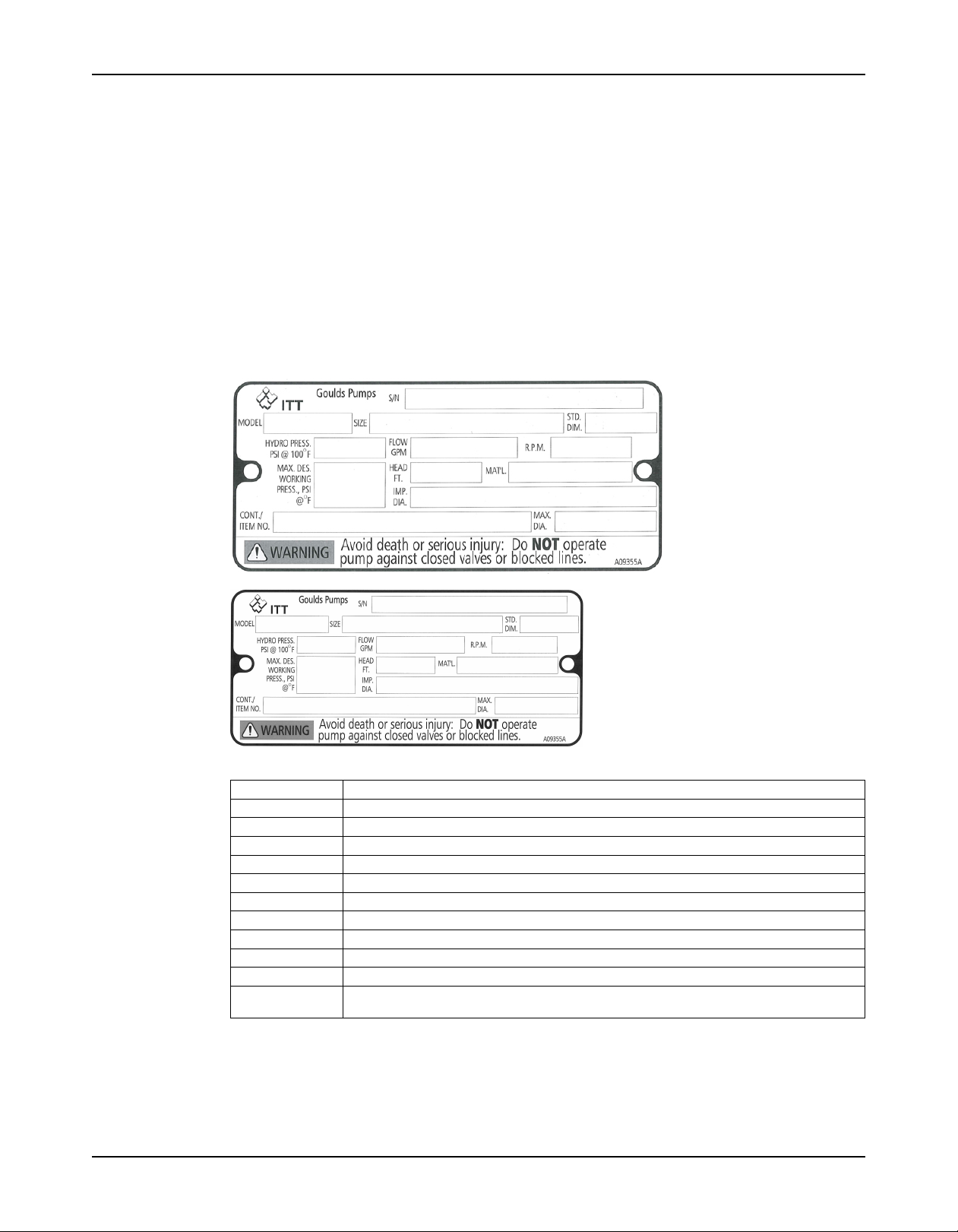
Nameplate information
Important information for ordering
Every pump has nameplates that provide information about the pump. The nameplates are
located on the casing and the bearing frame.
When you order spare parts, identify this pump information:
• Model
• Size
• Serial number
• Item numbers of the required parts
Refer to the nameplate on the pump casing for most of the information. See Parts List for item
numbers.
Nameplate on the pump casing using English units
Table 2: Explanation of nameplate on the pump casing
Nameplate field Explanation
IMPLR. DIA. Impeller diameter, in inches
MAX. DIA. Maximum impeller diameter, in inches
GPM Rated pump flow, in gallons per minute
FT HD Rated pump head, in feet
RPM Rated pump speed, revolutions per minute
MOD. Pump model
SIZE Size of the pump
STD. NO. Does not apply
MAT L. CONST. Material of which the pump is constructed
SER. NO. Serial number of the pump
MAX DSGN PSI Maximum pressure at 100ºF according to the pump design
@ 100ºF
18 XHD Installation, Operation, and Maintenance Manual
Page 21
Nameplate on the pump casing using metric units
Table 3: Explanation of the nameplate on the pump casing
Nameplate field Explanation
IMPLR. DIA. Impeller diameter
MAX. DIA. Maximum impeller diameter
M3/HR Rated pump flow, in cubic meters per hour
M HD Rated pump head, in meters
RPM Rated pump speed, in revolutions per minute
MOD. Pump model
SIZE Size of the pump
STD. NO. Does not apply
MAT L. CONST Material of which the pump is constructed
SER. NO. Serial number of the pump
MAX. DSGN KG/ Kilograms per square centimeter at 20°C
CM2@20°C
Product Description
Nameplate on the bearing frame
Table 4: Explanation of the nameplate on the bearing frame
Nameplate field Explanation
BRG. O. B. Outboard bearing designation
BRG. I. B. Inboard bearing designation
S/N Serial number of the pump
LUBE Lubricant, oil or grease
ATEX nameplate
Nameplate field Explanation
II Group 2
2 Category 2
G/D Pump can be used when gas and dust are present
T4 Temperature class
XHD Installation, Operation, and Maintenance Manual 19
Page 22

Product Description
NOTICE:
Make sure that the code classifications on the pump are compatible with the specific
environment in which you plan to install the equipment. If they are not compatible, do not
operate the equipment and contact your ITT representative before you proceed.
20 XHD Installation, Operation, and Maintenance Manual
Page 23
Installation
Preinstallation
Precautions
WARNING:
• When installing in a potentially explosive environment, make sure that the motor is properly certified.
• You must earth (ground) all electrical equipment. This applies to the pump equipment, the driver, and
any monitoring equipment. Test the earth (ground) lead to verify that it is connected correctly.
NOTICE:
Supervision by an authorized ITT representative is recommended to ensure proper installation.
Failure to do so may result in equipment damage or decreased performance.
Pump location guidelines
WARNING:
Assembled units and their components are heavy. Failure to properly lift and support this equipment can
result in serious physical injury and/or equipment damage. Lift equipment only at the specifically identified
lifting points. Lifting devices such as eyebolts, slings, and spreaders must be rated, selected, and used for
the entire load being lifted.
Installation
Guideline Explanation/comment
Keep the pump as close to the liquid source as This minimizes the friction loss and keeps the
practically possible. suction piping as short as possible.
Make sure that the space around the pump is This facilitates ventilation, inspection, maintenance,
sufficient. and service.
If you require lifting equipment such as a hoist or This makes it easier to properly use the lifting
tackle, make sure that there is enough space above equipment and safely remove and relocate the
the pump. components to a safe location.
Protect the unit from weather and water damage This is applicable if nothing else is specified.
due to rain, flooding, and freezing temperatures.
Do not install and operate the equipment in closed Acceptable devices:
systems unless the system is constructed with
properly-sized safety devices and control devices.
Take into consideration the occurrence of unwanted The best pump location for noise and vibration
noise and vibration. absorption is on a concrete floor with subsoil
If the pump location is overhead, undertake special Consider a consultation with a noise specialist.
precautions to reduce possible noise transmission.
Foundation requirements
Requirements
• The foundation must be able to absorb any type of vibration and form a permanent, rigid
support for the unit.
• The location and size of the foundation bolt holes must match those shown on the
assembly drawing provided with the pump data package.
• The foundation must weigh between two and three times the weight of the complete pump,
baseplate, and drive assembly.
• Pressure relief valves
• Compression tanks
• Pressure controls
• Temperature controls
• Flow controls
If the system does not include these devices,
consult the engineer or architect in charge before
you operate the pump.
underneath.
XHD Installation, Operation, and Maintenance Manual 21
Page 24
Installation
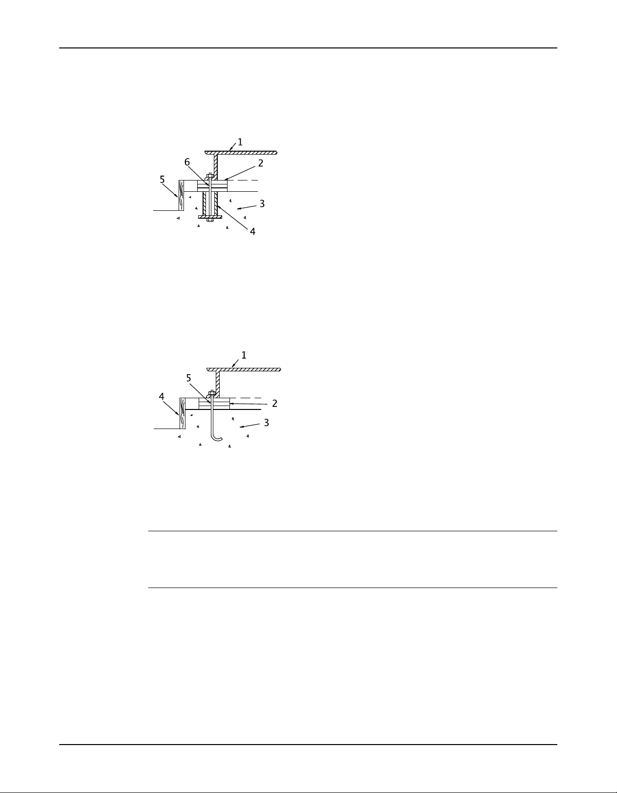
Sleeve-type bolts
• Provide a flat, substantial concrete foundation in order to prevent strain and distortion
when you tighten the foundation bolts.
• Sleeve-type and J-type foundation bolts are most commonly used. Both designs allow
movement for the final bolt adjustment.
1. Baseplate
2. Shims or wedges
3. Foundation
4. Sleeve
5. Dam
6. Bolt
J-type bolts
1. Baseplate
2. Shims or wedges
3. Foundation
4. Dam
5. Bolt
NOTICE:Slurry Pumps are typically driven with motors mounted overhead, coupled with Vbelts and sheaves. This configuration does not require the pump to be mounted and grouted
into place. The pump pedestal can be bolted onto a concrete foundation using J-type bolts or
Sleeve-type bolts, thru the pedestal or mounting feet.
Baseplate-mounting procedures
Prepare the baseplate for mounting
1. Remove all the attached equipment from the baseplate.
2. Clean the underside of the baseplate completely.
3. If applicable, coat the underside of the baseplate with an epoxy primer.
Use an epoxy primer only if you used an epoxy-based grout.
4. Remove the rust-proofing coat from the machined mounting pads using an appropriate
solvent.
22 XHD Installation, Operation, and Maintenance Manual
Page 25
5. Remove water and debris from the foundation-bolt holes.
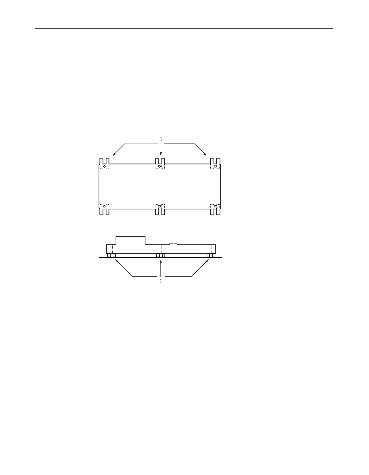
Install the baseplate using shims or wedges
Required tools:
• Two sets of shims or wedges for each foundation bolt
• Two machinist's levels
• Baseplate-leveling worksheet
This procedure is applicable to cast iron and fabricated steel baseplates.
1. If you use sleeve-type bolts, fill the bolt sleeves with packing material or rags to prevent
grout from entering the bolt holes.
2. Put the sets of wedges or shims on each side of each foundation bolt.
The sets of wedges should have a height of between 0.75 in. (19 mm) and 1.50 in. (38
mm).
Installation
1. Shims or wedges
Figure 5: Top view
1. Shims or wedges
Figure 6: Side view
3. Lower the baseplate carefully onto the foundation bolts.
4. Put the machinist's levels across the mounting pads of the driver and the mounting pads of
the pump.
NOTICE:
Remove all dirt from the mounting pads in order to make sure that you achieve the correct
leveling. Failure to do so can result in equipment damage or decreased performance.
5. Level the baseplate both lengthwise and across by adding or removing shims or moving the
wedges.
These are the leveling tolerances:
• A maximum difference of 0.125 in. (3.2 mm) lengthwise
• A maximum difference of 0.059 in. (1.5 mm) across
You can use the baseplate-leveling worksheet when you take the readings.
6. Hand-tighten the nuts for the foundation.
XHD Installation, Operation, and Maintenance Manual 23
Page 26
Installation
Install the baseplate using jackscrews
Tools required:
• Anti-seize compound
• Jackscrews
• Bar stock
• Two machinist's levels
• Baseplate-leveling worksheet
This procedure is applicable to the feature-fabricated steel baseplate and the advantage base
baseplate.
1. Apply an anti-seize compound on the jackscrews.
The compound makes it easier to remove the screws after you grout.
2. Lower the baseplate carefully onto the foundation bolts and perform these steps:
a) Cut the plates from the bar stock and chamfer the edges of the plates in order to reduce
stress concentrations.
b) Put the plates between the jackscrews and the foundation surface.
c) Use the four jackscrews in the corners in order to raise the baseplate above the
foundation.
Make sure that the distance between the baseplate and the foundation surface is
between 0.75 in. (19 mm) and 1.50 in. (38 mm).
d) Make sure that the center jackscrews do not touch the foundation surface yet.
1. Jackscrew
2. Baseplate
3. Foundation
4. Plate
3. Level the driver mounting pads:
NOTICE:
Remove all dirt from the mounting pads in order to make sure that you achieve the correct
leveling. Failure to do so can result in equipment damage or decreased performance.
a) Put one machinist's level lengthwise on one of the two pads.
b) Put the other machinist's level across the ends of the two pads.
24 XHD Installation, Operation, and Maintenance Manual
Page 27
Installation
c) Level the pads by adjusting the four jackscrews in the corners.
Make sure that the machinist's level readings are as close to zero as possible, both
lengthwise and across.
Use the baseplate-leveling worksheet when you take the readings.
1. Machinist's levels
2. Driver's mounting pads
3. Foundation bolts
4. Jackscrews
5. Grout hole
6. Pump's mounting pads
4. Turn the center jackscrews down so that they rest on their plates on the foundation surface.
5. Level the pump mounting pads:
NOTICE:
Remove all dirt from the mounting pads in order to make sure that you achieve the correct
leveling. Failure to do so can result in equipment damage or decreased performance.
a) Put one machinist's level lengthwise on one of the two pads.
b) Put the other level across the center of the two pads.
c) Level the pads by adjusting the four jackscrews in the corners.
Make sure that the machinist's level readings are as close to zero as possible, both
lengthwise and across.
1. Driver's mounting pads
2. Machinist's levels
3. Foundation bolts
4. Jackscrews
5. Grout hole
6. Pump's mounting pads
6. Hand-tighten the nuts for the foundation bolts.
7. Check that the driver's mounting pads are level and adjust the jackscrews and the
foundation bolts if necessary.
The correct level measurement is a maximum of 0.002 in./ft (0.0167 mm/m).
XHD Installation, Operation, and Maintenance Manual 25
Page 28
Installation
Direct-coupled baseplate-leveling worksheet
26 XHD Installation, Operation, and Maintenance Manual
Page 29
Install pump, driver, and v-belt drive
Install and align the sheaves
Before installing the driver onto an overhead motor mount or side-by-side base, ensure that
Foundation requirements and baseplate mounting procedures sections are complete.
1. Mount and fasten the pump on the pedestal spacer, foundation, or baseplate as applicable.
Use appropriate hardware.
2. For a motor that is mounted overhead, install the overhead motor mount.
3. For a motor that is mounted to the side of the pump, fasten the motor slide base on the
baseplate or pump. Fasten the motor slide base on the baseplate or foundation, as
applicable. Use appropriate hardware.
4. Mount the driver on the overhead motor mount or slide base, as applicable. Use
appropriate hardware.
5. Install the v-belt drive bushings and sheaves. See the installation instructions from the vbelt drive manufacturer.After the v-belt drive bushings and sheaves are installed, check the
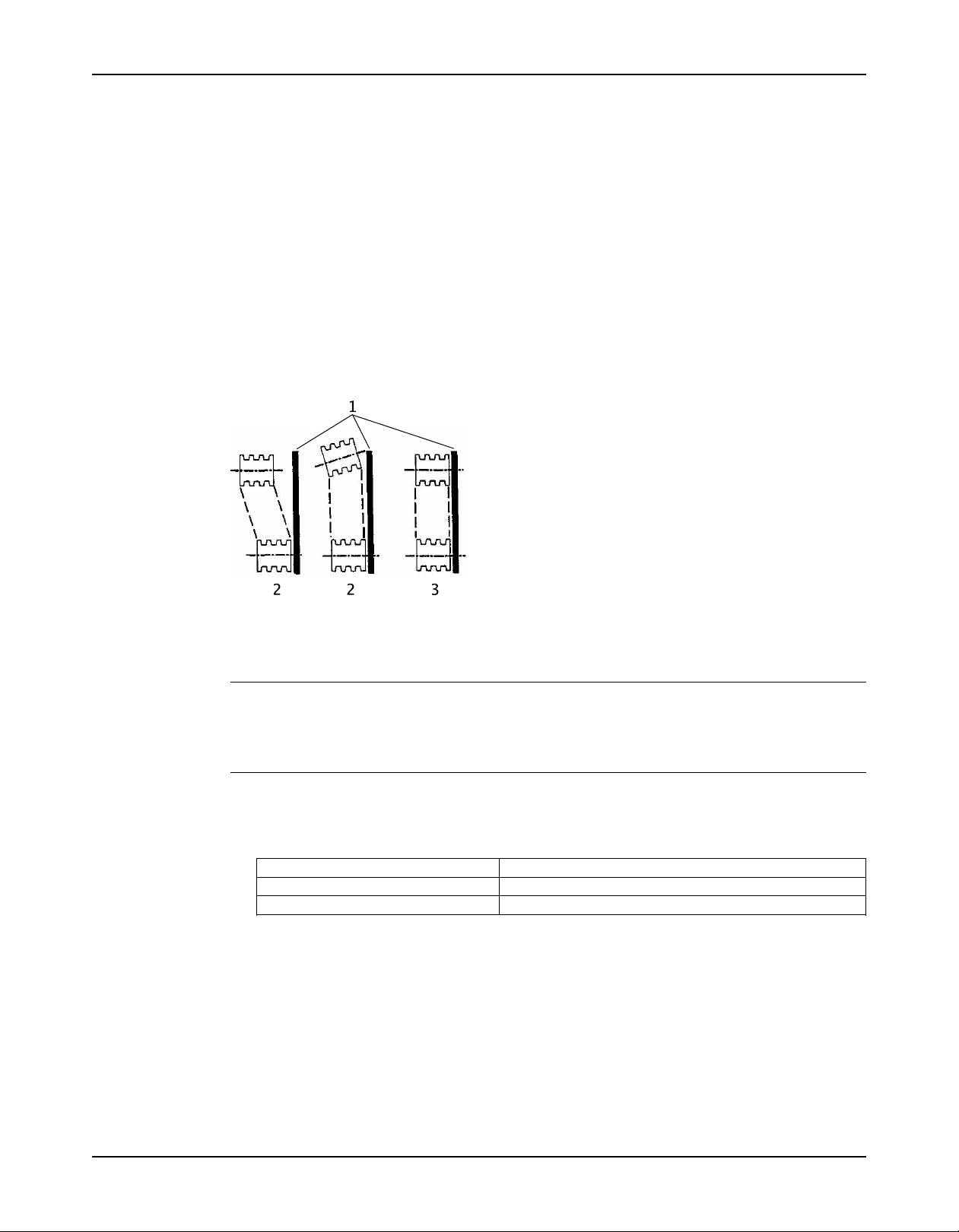
sheave alignment using a straight edge as shown in the following diagram.
Installation
1. Straight edge
2. Incorrect
3. Correct
NOTICE:
Make sure that the sheaves are properly aligned. Proper alignment is necessary to guarantee
the correct power transmission and speed ratio, and ensures minimum vibration and long drive
life.
Install and tension the belt
1. After alignment of the sheaves, reduce the center distance between the pump and motor
shafts so that the belts can be easily mounted into the sheave grooves.
For... Reduce the center distance by...
Overhead mounted motors Adjusting the leveling nuts
Side mounted motors Adjusting the motor slide base
Make sure that the center distance between the pump and motor shaft is reduced to the
point where the belts can be put on the sheaves without the use of force. Never roll or pry
the belts into place, as this could damage the belt cords.
2. After the belts are seated in the sheave grooves, increase the center distance between the
pump and motor shafts to tension the belts.
XHD Installation, Operation, and Maintenance Manual 27
Page 30
Installation
Refer to pump general arrangement drawing for center distance ranges.
Figure 7: V-belt tension
Many v-belt drive manufacturers offer tension measurement tools that can aid in setting
proper belt tension. Contact the v-belt drive manufacturer for more information.
3. Secure the overhead motor mount on slide base in place once the belts are properly
tensioned.
4. Install the unit after installation to ensure that the belts and sheaves do not come into
contact with the guard.
CAUTION:
The unit must not be operated without the proper drive guard in place. Operating the unit without the
drive guard in place could result in personal injury to operating personnel.
Install the pump, driver, and coupling
1. Mount and fasten the pump on the baseplate. Use applicable bolts.
2. Mount the driver on the baseplate. Use applicable bolts and hand tighten.
3. Install the coupling.
See the installation instructions from the coupling manufacturer.
Pump-to-driver alignment
Precautions
WARNING:
• Follow shaft alignment procedures in order to prevent catastrophic failure of drive components or
unintended contact of rotating parts. Follow the coupling installation and operation procedures from
the coupling manufacturer.
• Always disconnect and lock out power to the driver before you perform any installation or
maintenance tasks. Failure to disconnect and lock out driver power will result in serious physical
injury.
NOTICE:Proper alignment is the responsibility of the installer and the user of the unit. Check
the pump-to-driver alignment before you operate the unit. Failure to do so can result in
equipment damage or decreased performance.
NOTICE:
Proper alignment is the responsibility of the installer and the user of the unit. Check the
alignment of frame-mounted units before you operate the unit. Failure to do so can result in
equipment damage or decreased performance.
28 XHD Installation, Operation, and Maintenance Manual
Page 31

Alignment checks
When to perform alignment checks
You must perform alignment checks under these circumstances:
• The process temperature changes.
• The piping changes.
• The pump has been serviced.
Types of alignment checks
Type of check When it is used
Initial alignment (cold alignment) Prior to operation when the pump and the driver are at ambient
check temperature.
Final alignment (hot alignment) After operation when the pump and the driver are at operating
check temperature.
Initial alignment (cold alignment) checks
When Why
Before you grout the baseplate This ensures that alignment can be accomplished.
After you grout the baseplate This ensures that no changes have occurred during the grouting
After you connect the piping This ensures that pipe strains have not altered the alignment.
Installation
process.
If changes have occurred, you must alter the piping to remove pipe
strains on the pump flanges.
Final alignment (hot alignment) checks
When Why
After the first run This ensures correct alignment when both the pump and the driver
Periodically This follows the plant operating procedures.
are at operating temperature.
Permitted indicator values for alignment checks
NOTICE:
The specified permitted reading values are valid only at operating temperature. For cold
settings, other values are permitted. You must use the correct tolerances. Failure to do so can
result in misalignment and reduced pump reliability.
When dial indicators are used to check the final alignment, the pump and drive unit are
correctly aligned when the total indicator runout is a maximum of 0.004 in. (0.10 mm) at
operating temperature.
Cold settings for parallel vertical alignment
Introduction
This section shows the recommended preliminary (cold) settings for electric motor-driven
pumps based on different temperatures of pumped fluid. Consult driver manufacturers for
recommended cold settings for other types of drivers such as steam turbines and engines.
Recommended settings for model XHD
Pumped fluid temperature Recommended setting for driver shaft
50°F (10°C) 0.002 in. (0.05 mm), low
150°F (65°C) 0.001 in. (0.03 mm), high
250°F (120°C) 0.005 in. (0.12 mm), high
XHD Installation, Operation, and Maintenance Manual 29
Page 32

Installation
Alignment measurement guidelines
Guideline Explanation
Rotate the pump coupling half and the driver This prevents incorrect measurement.
coupling half together so that the indicator rods
have contact with the same points on the driver
coupling half.
Move or shim only the driver in order to make This prevents strain on the piping installations.
adjustments.
Make sure that the hold-down bolts for the driver This keeps the driver stationary since movement
feet are tight when you take indicator measure- causes incorrect measurement.
ments.
Make sure that the hold-down bolts for the driver This makes it possible to move the driver when you
feet are loose before you make alignment correc- make alignment corrections.
tions.
Check the alignment again after any mechanical This corrects any misalignments that an adjustment
adjustments. may have caused.
Attach the dial indicators for alignment
You must have two dial indicators in order to complete this procedure.
1. Attach two dial indicators on the pump coupling half (X):
a) Attach one indicator (P) so that the indicator rod comes into contact with the perimeter
of the driver coupling half (Y).
This indicator is used to measure parallel misalignment.
b) Attach the other indicator (A) so that the indicator rod comes into contact with the inner
end of the driver coupling half.
This indicator is used to measure angular misalignment.
2. Rotate the pump coupling half (X) in order to check that the indicators are in contact with
the driver coupling half (Y) but do not bottom out.
3. Adjust the indicators if necessary.
Pump-to-driver alignment instructions
Perform angular alignment for a vertical correction
Before you start this procedure, make sure that the dial indicators are set up correctly.
1. Set the angular alignment indicator to zero at the top-center position (12 o’clock) of the
driver coupling half (Y).
A unit is in angular alignment when the angular indicator (A) does not vary by more than
0.004 in (0.10 mm) as measured at 4 points 90º apart at the operating temperature.
2. Rotate the indicator to the bottom-center position (6 o’clock).
3. Record the indicator reading.
30 XHD Installation, Operation, and Maintenance Manual
Page 33

When the reading value is... Then...
Negative The coupling halves are farther apart at the
Positive The coupling halves are closer at the bottom than
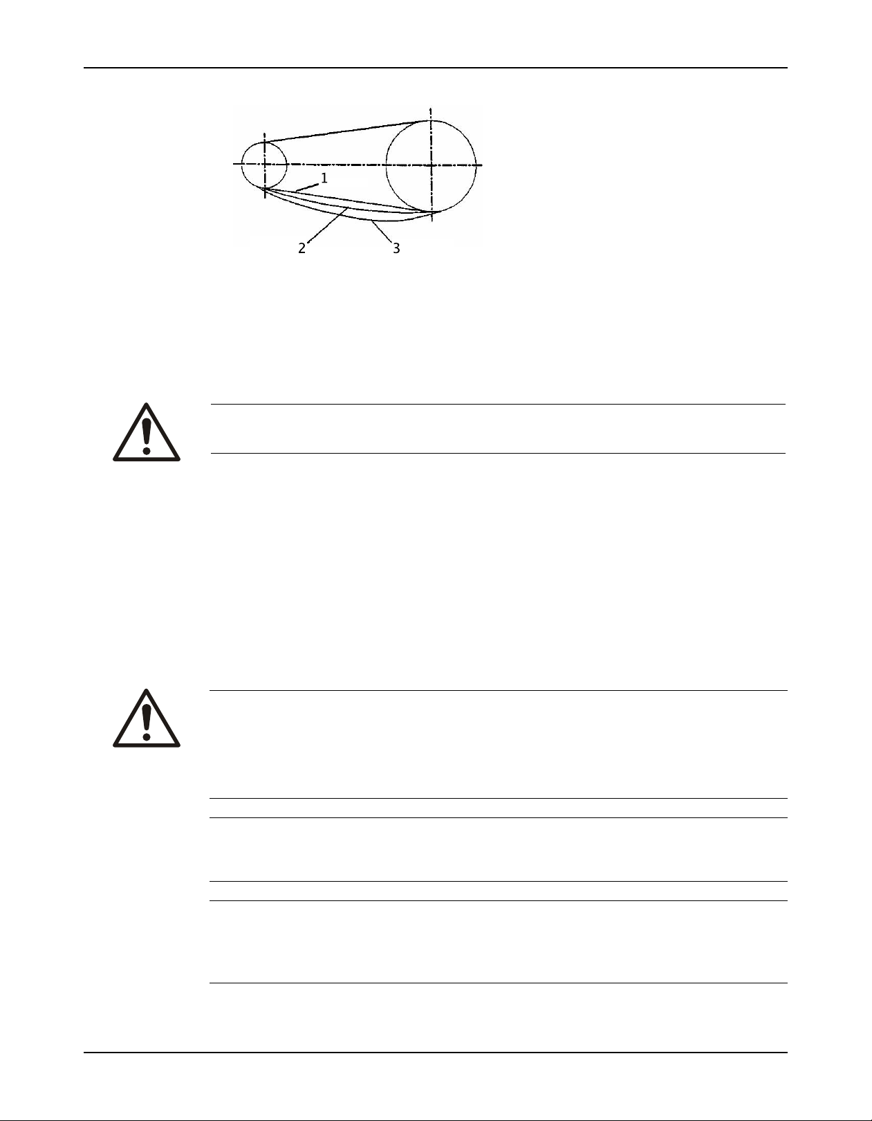
Figure 8: Side view of an incorrect vertical alignment
4. Repeat the previous steps until the permitted reading value is achieved.
Perform angular alignment for a horizontal correction
1. Set the angular alignment indicator (A) to zero on left side of the driver coupling half (Y),
90° from the top-center position (9 o’clock).
2. Rotate the indicator through the top-center position to the right side, 180° from the start
position (3 o’clock).
3. Record the indicator reading.
When the reading value is... Then...
Negative The coupling halves are farther apart on the right side than
the left. Perform one of these steps:
• Slide the shaft end of the driver to the left.
• Slide the opposite end to the right.
Positive The coupling halves are closer together on the right side
than the left. Perform one of these steps:
• Slide the shaft end of the driver to the right.
• Slide the opposite end to the left.
Installation
bottom than at the top. Perform one of these
steps:
• Add shims in order to raise the feet of the
driver at the shaft end.
• Remove shims in order to lower the feet of the
driver at the other end.
at the top. Perform one of these steps:
• Remove shims in order to lower the feet of the
driver at the shaft end.
• Add shims in order to raise the feet of the
driver at the other end.
Figure 9: Top view of an incorrect horizontal alignment
4. Repeat the previous steps until the permitted reading value is achieved.
Perform parallel alignment for a vertical correction
Refer to the alignment table in "Permitted indicator values for alignment checks" (see Table of
Contents for location of table) for the proper cold alignment value based on the motor
temperature rise and the pump operating temperature.
Before you start this procedure, make sure that the dial indicators are correctly set up.
A unit is in parallel alignment when the parallel indicator (P) does not vary by more than
0.004 in. (0.10 mm) as measured at four points 90° apart at the operating temperature.
XHD Installation, Operation, and Maintenance Manual 31
Page 34

Installation
1. Set the parallel alignment indicator (P) to zero at the top-center position (12 o’clock) of the
driver coupling half (Y).
2. Rotate the indicator to the bottom-center position (6 o’clock).
3. Record the indicator reading.
When the reading value is... Then...
Negative The pump coupling half (X) is lower than the
driver coupling half (Y). Remove shims of a
thickness equal to half of the indicator reading
value under each driver foot.
Positive The pump coupling half (X) is higher than the
driver coupling half (Y). Add shims of a thickness
equal to half of the indicator reading value to each
driver foot.
NOTICE:
Figure 10: Side view of an incorrect vertical alignment
4. Repeat the previous steps until the permitted reading value is achieved.
Perform parallel alignment for a horizontal correction
A unit is in parallel alignment when the parallel indicator (P) does not vary by more than
0.004 in. (0.10 mm) as measured at four points 90° apart at the operating temperature.
1. Set the parallel alignment indicator (P) to zero on the left side of the driver coupling half (Y),
90° from the top-center position (9 o’clock).
2. Rotate the indicator through the top-center position to the right side, 180° from the start
position (3 o’clock).
3. Record the indicator reading.
When the reading value is... Then...
Negative The driver coupling half (Y) is to the left of the
Positive The driver coupling half (Y) is to the right of the
4. Slide the driver carefully in the appropriate direction.
NOTICE:Make sure to slide the driver evenly. Failure to do so can negatively affect
horizontal angular correction.
pump coupling half (X).
pump coupling half (X).
Figure 11: Top view of an incorrect horizontal alignment
5. Repeat the previous steps until the permitted reading value is achieved.
32 XHD Installation, Operation, and Maintenance Manual
Page 35

Perform complete alignment for a vertical correction
A unit is in complete alignment when both the angular indicator (A) and the parallel indicator (P)
do not vary by more than 0.002 in. (0.05 mm) as measured at four points 90° apart.
1. Set the angular and parallel dial indicators to zero at the top-center position (12 o’clock) of
the driver coupling half (Y).
2. Rotate the indicators to the bottom-center position (6 o’clock).
3. Record the indicator readings.
4. Make corrections according to the separate instructions for angular and parallel alignment
until you obtain the permitted reading values.
Perform complete alignment for a horizontal correction
A unit is in complete alignment when both the angular indicator (A) and the parallel indicator (P)
do not vary by more than 0.004 in. (0.10 mm) as measured at four points 90° apart.
1. Set the angular and parallel dial indicators to zero at the left side of the driver coupling half
(Y), 90° from the top-center position (9 o’clock).
2. Rotate the indicators through the top-center position to the right side, 180° from the start
position (3 o’clock).
3. Record the indicator readings.
4. Make corrections according to the separate instructions for angular and parallel alignment
until you obtain the permitted reading values.
Installation
Grout the baseplate
Required equipment:
• Cleaners: Do not use an oil-based cleaner because the grout will not bond to it. See the
instructions provided by the grout manufacturer.
• Grout: Non-shrink grout is recommended.
1. Clean all the areas of the baseplate that will come into contact with the grout.
2. Build a dam around the foundation.
3. Thoroughly wet the foundation that will come into contact with the grout.
4. Pour grout through the grout hole into the baseplate up to the level of the dam.
When you pour the grout, remove air bubbles from it by using one of these methods:
• Puddle with a vibrator.
• Pump the grout into place.
5. Allow the grout to set.
1. Baseplate
2. Shims or wedges
3. Grout
4. Foundation
5. Sleeve
6. Dam
7. Bolt
XHD Installation, Operation, and Maintenance Manual 33
Page 36

Installation
6. Fill the remainder of the baseplate with grout, and allow the grout to set for at least 48
hours.
1. Baseplate
2. Grout
3. Foundation
4. Dam
5. Bolt
7. Tighten the foundation bolts.
8. Recheck the alignment.
Piping checklists
General piping checklist
Precautions
CAUTION:
• Never draw piping into place by using force at the flanged connections of the pump. This can
impose dangerous strains on the unit and cause misalignment between the pump and driver. Pipe
strain adversely affects the operation of the pump, which results in physical injury and damage to
the equipment.
• Vary the capacity with the regulating valve in the discharge line. Never throttle the flow from the
suction side. This action can result in decreased performance, unexpected heat generation, and
equipment damage.
CAUTION:
Piping guidelines
Guidelines for piping are given in the Hydraulic Institute Standards available from the Hydraulic
Institute at 9 Sylvan Way, Parsippany, NJ 07054-3802. You must review this document before
you install the pump.
Checklist
Check Explanation/comment Checked
Check that all piping is supported This helps to prevent:
independently of, and lined up
naturally with, the pump flange.
Keep the piping as short as pos- This helps to minimize friction losses.
sible.
Check that only necessary fittings This helps to minimize friction losses.
are used.
• Strain on the pump
• Misalignment between the pump and the drive unit
• Wear on the pump bearings and the coupling
• Wear on the pump bearings, seal, and shafting
34 XHD Installation, Operation, and Maintenance Manual
Page 37

Check Explanation/comment Checked
Do not connect the piping to the —
pump until:
• The grout for the baseplate or
sub-base becomes hard.
• The hold-down bolts for the
pump and the driver are tightened.
Make sure that all the piping joints This prevents air from entering the piping system or
and fittings are airtight. leaks that occur during operation.
If the pump handles corrosive
fluids, make sure that the piping
allows you to flush out the liquid
before you remove the pump.
If the pump handles liquids at This helps to prevent misalignment due to linear expanelevated temperatures, make sion of the piping.
sure that the expansion loops and
joints are properly installed.
Example: Installation for expansion
Correct Incorrect
This illustration shows a correct installation for This illustration shows an incorrect installation for
expansion: expansion:
Installation
1. Expansion loop/joint
Suction-piping checklist
Performance curve reference
Suction-piping checks
Check Explanation/comment Checked
Check that the distance between This minimizes the risk of cavitathe inlet flange of the pump and tion in the suction inlet of the
closest flow disruption (elbow, pump due to turbulence.
valve, strainer, or expansion joint)
is at least five pipe diameters.
Check that elbows in general do See the Example sections for ilnot have sharp bends. lustrations.
XHD Installation, Operation, and Maintenance Manual 35
Page 38

Installation
Check Explanation/comment Checked
Check that the suction piping is The suction piping must never
one or two sizes larger than the have a smaller diameter than the
suction inlet of the pump. suction inlet of the pump.
Install an eccentric reducer be- See the Example sections for iltween the pump inlet and the lustrations.
suction piping.
Suction pipe reducers should
have no more than two pipe diameter changes per reducer.
Check that the eccentric reducer See the example illustrations.
at the suction flange of the pump
has the following properties:
• Sloping side down
• Horizontal side at the top
If suction strainers or suction bells Suction strainers help to prevent
are used, check that they are at clogging.
least three times the area of the
suction piping.
If more than one pump operates This recommendation helps you to
from the same liquid source, achieve a higher pump perforcheck that separate suction-piping mance.
lines are used for each pump.
If necessary, make sure that the —
suction piping includes a drain
valve and that it is correctly installed.
Mesh holes with a minimum diameter of 1/16 in. (1.6 mm) are
recommended.
Liquid source below the pump
Check Explanation/comment Checked
Make sure that the suction piping This helps to prevent the occuris free from air pockets. rence of air and cavitation in the
Check that the suction piping —
slopes upwards from the liquid
source to the pump inlet.
If the pump is not self-priming, Use a foot valve with a diameter
check that a device for priming the that is at least equivalent to the
pump is installed. diameter of the suction piping.
Liquid source above the pump
Check Explanation/comment Checked
Check that an isolation valve is This permits you to close the line
installed in the suction piping at a during pump inspection and maindistance of at least two times the tenance.
pipe diameter from the suction
inlet.
Make sure that the suction piping This helps to prevent the occuris free from air pockets. rence of air and cavitation in the
Check that the piping is level or —
slopes downward from the liquid
source.
Make sure that no part of the —
suction piping extends below the
suction flange of the pump.
Make sure that the suction piping This prevents air from entering the
is adequately submerged below pump through a suction vortex.
the surface of the liquid source.
pump inlet.
Do not use the isolation valve to
throttle the pump. Throttling can
cause these problems:
• Loss of priming
• Excessive temperatures
• Damage to the pump
• Voiding the warranty
pump inlet.
36 XHD Installation, Operation, and Maintenance Manual
Page 39

Example: Elbow (or other flow disruption) close to the pump suction inlet
Correct Incorrect
The correct distance between the inlet flange of the
pump and the closest flow disruption (elbow, valve,
strainer, or expansion joint) must be a least five pipe
diameters.
NOTICE:This illustration shows an incorrectly in-
NOTICE:This illustration shows a correctly installed
elbow.
stalled elbow.
Example: Suction piping equipment
Correct Incorrect
Installation
1. Suction pipe sloping upwards from liquid source
2. Long-radius elbow
3. Strainer
4. Foot valve
5. Eccentric reducer with a level top
NOTICE:This illustration shows correctly installed
equipment for the suction piping.
1. Air pocket, because the eccentric reducer is not
used and because the suction piping does not
slope gradually upward from the liquid source
NOTICE:This illustration shows incorrectly installed
equipment for the suction piping.
Discharge piping checklist
Checklist
Check Explanation/comment Checked
Check that an isolation valve is in- The isolation valve is required for:
stalled in the discharge line.
XHD Installation, Operation, and Maintenance Manual 37
• Priming
• Regulation of flow
• Inspection and maintenance of the pump
See Example: Discharge piping equipment for
illustrations.
Page 40

Installation
Check Explanation/comment Checked
Check that a check valve is installed in The location between the isolation valve and the
the discharge line, between the isola- pump allows inspection of the check valve.
tion valve and the pump discharge
outlet.
If increasers are used, check that they See Example: Discharge piping equipment for
are installed between the pump and illustrations.
the check valve.
If quick-closing valves are installed in This protects the pump from surges and water
the system, check that cushioning de- hammer.
vices are used.
Example: Discharge piping equipment
Correct Incorrect
The check valve prevents damage to the pump and
seal due to the back flow through the pump, when
the drive unit is shut off. It is also used to restrain
the liquid flow.
See Example: Discharge piping equipment for
illustrations.
1. Bypass line
2. Shut-off valve
3. Check valve
4. Discharge isolation valve
Bypass-piping considerations
When to use a bypass line
Provide a bypass line for systems that require operation at reduced flows for prolonged
periods. Connect a bypass line from the discharge side (before any valves) to the source of
suction.
When to install a minimum-flow orifice
You can size and install a minimum-flow orifice in a bypass line in order to prevent bypassing
excessive flows. Consult your ITT representative for assistance in sizing a minimum-flow
orifice.
When a minimum-flow orifice is unavailable
Consider an automatic recirculation control valve or solenoid-operated valve if a constant
bypass (minimum-flow orifice) is not possible.
1. Check valve (incorrect position)
2. The isolation valve should not be positioned
between the check valve and the pump.
38 XHD Installation, Operation, and Maintenance Manual
Page 41

Auxiliary-piping checklist
Precautions
WARNING:
• Cooling systems such as those for bearing lubrication and mechanical-seal systems must be
operating properly to prevent excess heat generation, sparks, and premature failure.
• Sealing systems that are not self-purging or self-venting, such as plan 23, require manual venting
prior to operation. Failure to do so will result in excess heat generation and seal failure.
NOTICE:
The mechanical seal must have an appropriate seal-flush system. Otherwise, excess heat
generation and seal failure can occur.
When to install
You may need to install auxiliary piping for bearing cooling, seal-chamber cover cooling,
mechanical seal flush, or other special features supplied with the pump. Consult the pump data
sheet for specific auxiliary piping recommendations.
Checklist
Check Explanation/comment Checked
Check that the minimum flow for –
each component is 1 gpm (4 lpm).
If the bearing and seal chamber
cover cooling are provided, then
the auxiliary piping must flow at 2
gpm (8 lpm).
Check that the cooling water pres- –
sure does not exceed 100 psig
(7.0 kg/cm2).
Installation
Final piping checklist
Check Explanation/comment Checked
Check that the shaft rotates Rotate the shaft by hand. Make
smoothly. sure there is no rubbing that can
Re-check the alignment to make If pipe strain exists, then correct
sure that pipe strain has not the piping.
caused any misalignment.
lead to excess heat generation or
sparks.
XHD Installation, Operation, and Maintenance Manual 39
Page 42

Commissioning, Startup, Operation, and Shutdown
Commissioning, Startup, Operation, and
Shutdown
Preparation for startup
DANGER:
Avoid death or serious injury. Explosion and/or seizure of pump can cause fire and/or burns. Never
operate pump past the pressure and temperature limits shown on the nameplate on the pump.
WARNING:
• Failure to follow these precautions before you start the unit will lead to serious personal injury and
equipment failure.
• Do not operate the pump below the minimum rated flows or with the suction or discharge valves
closed. These conditions can create an explosive hazard due to vaporization of pumped fluid and
can quickly lead to pump failure and physical injury.
• Avoid death or serious injury. Leaking fluid can cause fire and/or burns. Operating the pump above
maximum rated flow shown on the pump curve leading to an increase in horsepower and vibration
along with an increase in NPSHr resulting in mechanical seal and/or shaft failure and/or loss of
prime.
• Avoid death or serious injury. Leaking fluid can cause fire and/or burns. Speed of pump must reach
2000 rpm for 2 pole motors and 1000 rpm for 4 pole motors within 10 seconds or an increase in
vibration and rotor deflection and decrease in rotor stability leading to mechanical seal and/or shaft
failure and/or pump seizure can occur.
• Always disconnect and lock out power to the driver before you perform any installation or
maintenance tasks. Failure to disconnect and lock out driver power will result in serious physical
injury.
• Operating the pump in reverse rotation can result in the contact of metal parts, heat generation, and
breach of containment.
• Avoid death or serious injury. Explosion and/or seizure of pump can cause fire and/or burns. Assure
balance line is installed and either piped to the pump suction or back to the suction vessel to avoid
vaporization of pumped fluid.
Precautions
DANGER:
Avoid death or serious injury. Leaking fluid can cause fire and/or burns. Assure all openings are sealed
off prior to filling pump.
NOTICE:
• Verify the driver settings before you start any pump.
• Make sure that the warm-up rate does not exceed 2.5°F (1.4°C) per minute.
• Risk of damage to the mechanical seal or shaft sleeve on units supplied with cartridge
mechanical seals. Prior to startup, make sure to tighten the set screws in the seal locking
ring and remove the centering clips.
You must follow these precautions before you start the pump:
• Flush and clean the system thoroughly to remove dirt or debris in the pipe system in order
to prevent premature failure at initial startup.
• Bring variable-speed drivers to the rated speed as quickly as possible.
• If temperatures of the pumped fluid will exceed 200°F (93°C), then warm up the pump prior
to operation. Circulate a small amount of fluid through the pump until the casing
temperature is within 100°F (38°C) of the fluid temperature. Accomplish this by flowing
40 XHD Installation, Operation, and Maintenance Manual
Page 43

fluid from pump inlet to discharge drain (optionally, the casing vent can be included in
warm-up circuit but not required). Soak for (2) hours at process fluid temperature.
At initial startup, do not adjust the variable-speed drivers or check for speed governor or overspeed trip settings while the variable-speed driver is coupled to the pump. If the settings have
not been verified, then uncouple the unit and refer to instructions supplied by the driver
manufacturer.
After observing the precautions above, the v-belt or coupling guard must be removed to check
driver rotation and set the impeller clearance. Refer to the appropriate guard removal
instructions specific to your unit(s).
Remove the V-belt drive guard
1. Remove the drive guard assembly hardware as appropriate.
2. Remove the hardware that secures the drive guard in place.
3. Disassemble and remove the drive guard assembly.
Commissioning, Startup, Operation, and Shutdown
Remove the coupling guard
1. Remove the nut, bolt, and washers from the slotted hole in the center of the coupling guard.
2. Slide the driver half of the coupling guard toward the pump.
3. Remove the nut, bolt, and washers from the driver half of the coupling guard.
4. Remove the driver-side end plate.
5. Remove the driver half of the coupling guard:
a) Slightly spread the bottom apart.
b) Lift upwards.
6. Remove the remaining nut, bolt, and washers from the pump half of the coupling guard.
It is not necessary to remove the end plate from the pump side of the bearing housing. You
can access the bearing-housing tap bolts without removing this end plate if maintenance of
internal pump parts is necessary.
7. Remove the pump half of the coupling guard:
a) Slightly spread the bottom apart.
XHD Installation, Operation, and Maintenance Manual 41
Page 44

Commissioning, Startup, Operation, and Shutdown
b) Lift upwards.
1. Coupling guard
2. Coupling
Check the rotation
WARNING:
• Operating the pump in reverse rotation can result in the contact of metal parts, heat generation, and
breach of containment.
• Always disconnect and lock out power to the driver before you perform any installation or
maintenance tasks. Failure to disconnect and lock out driver power will result in serious physical
injury.
1. Lock out power to the driver.
2. Make sure that the coupling hubs or v-belt sheaves are fastened securely to the shafts.
3. Make sure that the coupling spacer is removed, if applicable.
The pump ships with the coupling spacer removed.
4. Unlock power to the driver.
5. Make sure that everyone is clear, and then jog the driver long enough to determine that the
direction of rotation corresponds to the arrow on the bearing housing or casing.
6. Lock out power to the driver.
Impeller-clearance check
The impeller-clearance check ensures the following:
• The pump turns freely.
• The pump operates at optimal efficiency for long equipment life and low energy
consumption.
Impeller axial clearances
Total axial adjustment
The total axial adjustment of the impeller between the suction seal ring and the stuffing box
cover should be as noted in the chart below.
42 XHD Installation, Operation, and Maintenance Manual
Page 45

Impeller clearance (total travel)
Pump size Impeller Maximum Total Impeller Minimum Total
XHD80 0.37 (9.4) 0.10 (2.6)
XHD125 0.39 (9.8) 0.10 (2.6)
XHD150 0.43 (10.8) 0.13 (3.3)
XHD200 0.47 (11.8) 0.16 (4.1)
XHD250 0.47 (11.9) 0.16 (4.0)
XHD300 0.51 (12.8) 0.18 (4.6)
Impeller-clearance setting
Importance of a proper impeller clearance
A proper impeller clearance ensures that the pump runs at high performance.
WARNING:
• The pump should be run for a period of 15 minutes to verify the impeller is properly tightened onto
the shaft. In addition to verifying the impeller is properly tightened, it is necessary to verify that the
bearing frame adjustment plate bolts (352G) and nuts (427D) are properly secured and tight. Failure
to check that the impeller is tight and the bearing frame adjustment plate bolts and nuts are properly
tightened can result in the rotating element shifting during operation.
Commissioning, Startup, Operation, and Shutdown
Clearance inches (mm) Clearance inches (mm)
• The impeller clearance setting procedure must be followed. Improperly setting the clearance or not
following any of the proper procedures can result in sparks, unexpected heat generation, and
equipment damage.
The front clearance is set at .51 mm (0.020 in) at the factory but could change due to piping
attachment during installation. A change in pump performance may be noted over time by a
drop in head or flow or an increase in power required.
Table 5: Impeller clearance methods
The XHD and XHD Value Option models have different methods of setting the impeller clearance.
Pump Model Method
XHD The impeller clearance is set by measuring the gap between the rear shroud of the
XHD Value Option The impeller clearance is set by measuring the gap between the front of the impeller
XHD Installation, Operation, and Maintenance Manual 43
impeller and the casing volute liner, and measuring the gap between the front of the
impeller and the suction seal ring clearance.
Skip to the "Set Impeller to Suction seal Ring Clearance Dial Dial Indicator Method XHD" step.
After impeller rear clearance has been set on the XHD, the suction seal ring
clearance must also be set.
and the suction side liner. Use the "Set the impeller clearance dial indicator method
- XHD Value Option" step.
Page 46

Commissioning, Startup, Operation, and Shutdown
Set impeller to Suction Seal Ring Clearance Dial Indicator Method
WARNING:
Always disconnect and lock out power to the driver before you perform any installation or maintenance
tasks. Failure to disconnect and lock out driver power will result in serious physical injury.
All of the instructions that are stated in the following steps are based on viewing the unit from
the rearward (drive) end.
1. Remove the coupling or v-belt guard.
2. Loosen the two adjusting nuts (415A) on the forward sides of the bearing frame adjustment
plates (234F) by turning them counterclockwise.
3. Loosen but do not remove the adjustment plate hold-down bolts (352G) and nuts (427D)
that clamp the bearing frame adjustment plates (234F) to the pedestal (131). Do not
remove the adjustment plate hardware. Keep hardware finger tight to keep the power frame
constrained to the pedestal.
4. Back up the Impeller: Turn the two adjusting nuts (415A) on the rearward sides of the
bearing frame adjustment plates (234F) counterclockwise sequentially, 1/2 of a turn each at
a time, to draw the power end and impeller (101) backward until the face of the rear pump
out vanes of the impeller contacts the volute liner (561). Turn the shaft (122) clockwise to
ensure that there is contact between the impeller (101) and volute liner (561). Stop turning
the adjusting nuts (415A) when a firm drag is encountered.
5. Place and zero the indicator: Place the dial indicator so that the button contacts either the
shaft end, face of the coupling, face of the sheave bushing, or on the face of the bearing
end cover. Zero the indicator.
6. Loosen the two adjusting nuts (415A) on the rear sides of the bearing frame adjustment
plates (234F) that were tightened in step 4 above by turning them counter clockwise.
7. Move Impeller forward the sum of impeller back clearance plus the impeller front clearance
from table 7: Turn the two adjusting nuts (415A) on the forward sides of the bearing frame
adjustment plates (234F) clockwise sequentially, 1/2 of a turn at a time, to draw the power
end forward until there is a 2.54mm (.100 in) or 3.0 mm (.118 in) gap between the impeller
(101) and suction volute liner (561) as measured on the dial indicator.
44 XHD Installation, Operation, and Maintenance Manual
Page 47

Commissioning, Startup, Operation, and Shutdown
8. Tighten the adjustment plate hold-down bolts (352G) and nuts (427D) that clamp the
bearing frame adjustment plates (234F) to the pedestal (131). Make sure that the dial
indicator reading remains at the proper setting.
9. Loosen the three seal ring jam nuts (357B) by turning them counterclockwise.
10. Move Seal Ring to contact to the impeller: Turn the three square head adjusting bolts
(356F) sequentially counter clockwise, 1/3 of a turn each at a time, until the seal ring (822)
contacts the impeller (101) and is square with the wear surface of the impeller. Turn the
shaft (122) clockwise while performing step 10 to ensure there is contact between the seal
ring (822) and impeller (101). Stop turning the square head adjusting bolts (356F) when a
firm drag is encountered.
11. Tighten the seal ring adjusting bolt jam nuts (357B) by turning counterclockwise until the
nuts contact the suction casing (100A).
12. Loosen the adjustment plate hold down bolts (352G) and nuts (427D).
13. Loosen the two adjusting nuts (415A) on the forward sides of the bearing frame
adjustment plates (234F) by turning them counterclockwise.
14. Back up the impeller .51mm (.020 in): Turn the two adjusting nuts (415A) on the rearward
sides of the bearing frame adjustment plates (234F) sequentially clockwise, 1/2 of a turn
each at a time, to draw the power end backward until the impeller (101) dial indicator
measures the proper field setting impeller back clearance from table 7. To verify the correct
impeller to suction seal ring clearance has been made, a feeler gage can be inserted thru
the casing suction between the impeller (101) and seal ring (822) in 3 places to assure the
seal ring is square to the impeller face.
15. Tighten the adjustment plate hold-down bolts (352G) and nuts (427D) that clamp the
bearing frame adjustment plates (234F) to the pedestal (131). Make sure that the dial
indicator reading remains at the proper setting.
16. Tighten the two adjusting nuts (415A) on the forward side of the bearing frame adjustment
plates (234F) by turning counterclockwise until they contact the adjustment plates. This
procedure should yield .51mm (.02in) gap between the impeller (101) and suction seal ring
(822), and leave the approximate back clearance noted in table 7 gap between the rear
shroud of the impeller (101) and the volute liner (561).
XHD Installation, Operation, and Maintenance Manual 45
Page 48

Commissioning, Startup, Operation, and Shutdown
Table 6: Impeller clearance
Pump Size Field Setting Impeller Back Field Setting Impeller Front
XHD80 0.08 (2) 0.02 (.51)
XHD125 0.08 (2) 0.02 (.51)
XHD150 0.08 (2) 0.02 (.51)
XHD200 0.1 (2.5) 0.02 (.51)
XHD250 0.1 (2.5) 0.02 (.51)
XHD300 0.1 (2.5) 0.02 (.51)
Clearance inches (mm) Clearance inches (mm)
Table 7: Field setting impeller back clearance with an expeller
Pumps that have the dynamic seal option require different impeller running clearances to maximize
expeller performance. Refer to the table below for running clearances for pumps with expeller.
Pump Size Field Setting Impeller Back Field Setting Impeller Seal Ring
XHD80 0.04 (1.02) 0.02 (.51)
XHD125 0.06 (1.52) 0.02 (.51)
XHD150 0.06 (1.52) 0.02 (.51)
XHD200 0.06 (1.52) 0.02 (.51)
XHD250 0.08 (2.03) 0.02 (.51)
XHD300 0.08 (2.03) 0.02 (.51)
Clearance inches (mm) Clearance inches (mm)
Set impeller clearance dial indicator method - XHD
WARNING:
Always disconnect and lock out power to the driver before you perform any installation or maintenance
tasks. Failure to disconnect and lock out driver power will result in serious physical injury.
All of the instructions that are stated in the following steps are based on viewing the unit from
the rearward (drive) end.
1. Remove the coupling or v-belt guard.
2. Loosen the two adjusting nuts (415A) on the forward sides of the bearing frame adjustment
plates (234F) by turning them clockwise.
3. Loosen but do not remove the adjustment plate hold-down bolts (352G) and nuts (427D)
that clamp the bearing frame adjustment plates (234F) to the pedestal (131).
Do not remove the adjustment plate hardware. Keep hardware finger tight to keep the
power frame constrained to the pedestal.
4. Turn the two adjusting nuts (415A) on the forward sides of the bearing frame adjustment
plates (234F) sequentially clockwise, 1/2 of a turn each at a time, to draw the power end
forward until the impeller (101) contacts the Suction Liner (562).
5. Turn the shaft (122) clockwise while performing step 4 above to ensure that there is contact
between the impeller (101) and Suction Liner (562). Stop turning the forward adjusting nuts
when a firm drag is encountered.
46 XHD Installation, Operation, and Maintenance Manual
Page 49

6. Place the dial indicator so that the button contacts either the shaft end, face of the coupling,
or face of the sheave bushing or the face of the bearing end cover. Zero the indicator.
7. Turn the two adjusting nuts (415A) on the rear sides of the bearing frame adjustment plates
(234F) sequentially counterclockwise, 1/2 of a turn each at a time, to draw the power end
and impeller (101) backward until there is an approximate 0.02 inch (.50 mm) gap between
the impeller (101) and suction liner (562) as measured on the dial indicator.
8. Tighten the adjustment plate hold-down bolts (352G) and nuts (427D) that clamp the
bearing frame adjustment plates (234F) to the pedestal (131). Make sure that the dial
indicator reading remains at the proper setting.
9. Tighten the two adjusting nuts (415A) on the rearward side of the bearing frame adjustment
plates (234F) that were loosened in step 5 above by turning them clockwise. Make sure
that the dial indicator reading remains at the proper setting.
10. Replace the coupling or v-belt guard.
Suction seal ring clearance check - XHD only
WARNING:
Always disconnect and lock out power to the driver before you perform any installation or maintenance
tasks. Failure to disconnect and lock out driver power will result in serious physical injury.
In addition to checking the impeller clearance, the suction seal ring clearance on the XHD
model must also be checked according to the following instructions for optimal efficiency and
wear.
All of the instructions that are stated in the following steps are based on viewing the unit from
the rearward (drive) end.
1. Loosen the three seal ring jam nuts (357B) by turning them counterclockwise.
2. Turn the three square head adjusting bolts (356F) sequentially clockwise, 1/3 of a turn each
at a time, until the seal ring (822) contacts the impeller (101).
3. Turn the shaft (122) clockwise while performing step 2 above to ensure there is contact
between the seal ring (822) and impeller (101). Stop turning the square head adjusting
bolts when a firm drag is encountered.
4. Turn the three square head adjusting bolts (356F) sequentially counterclockwise, 1/3 of a
turn each at a time, while measuring the gap between the impeller (101) and seal ring (822)
using a set of feeler gauges inserted in the suction of the pump.
5. Continue adjusting the square head adjusting bolts as outlined in step 3 above until there is
the appropriate gap from table 7 between the suction seal ring (822) and the impeller (101).
The gap is properly established when a appropriate feeler gauge fits snugly into the space
between the impeller (101) and seal ring (822).
6. Lock the square head adjusting bolts (356F) in place by turning the jam nuts (357B)
clockwise until tightened against the suction half casing (100A).
After the clearances have been checked/set, the v-belt or coupling guard can be re-installed.
Refer to the appropriate guard installation instructions specific to your unit(s).
Impeller to Suction liner / Seal Ring Front clearance
0.02 inches
0.50 mm
Commissioning, Startup, Operation, and Shutdown
Install the V-belt drive guard
1. Assembly the drive guard as necessary. Use appropriate hardware.
2. Secure the drive guard in place to the foundation or baseplate and pump as necessary.
Use appropriate hardware.
XHD Installation, Operation, and Maintenance Manual 47
Page 50

Commissioning, Startup, Operation, and Shutdown
V-Belt drive operation
V belt drive installation checks
Use the following steps and guidelines to make sure that the v-belt drive is properly installed
and that the belts are properly tensioned.
1. Operate the drive for a few minutes as the belts seat into the sheave grooves.
2. Observe the operation of the drive under its highest load condition, which is usually at
startup.
3. A slight bowing of the slack side of the drive indicates proper tension.
4. The following indicate improper belt tensioning:
a) If the slack side of the drive remains too taut during peak load, the drive is too tight.
b) Excessive bowing or slippage of the slack side indicates insufficient tension.
c) If the belts squeal as the motor is started, or at some subsequent peak load, the belts
are not tight enough to deliver the torque that is demanded by the motor.
5. If any of the conditions that are listed under (4) are evident, stop the drive and readjust the
belts.
6. If conditions persist, check the sheave alignment as outlined in the previous sections.
7. The belt tension on a newly installed drive should be checked throughout the first day of
continuous operation by observing the slack side span. After a few days of operation, the
belts will fully seat themselves in the sheave grooves, and further readjustment may be
necessary. Use the steps and guidelines above as necessary.
V-belt drive monitoring and protection
1. Use all of the information in these sections to ensure that the v-belt drive is properly
installed for correct operation and long life.
2. Keep the v-belts clean. Exposure to dirt and grease can reduce belt life. Maintaining a
clean drive is the one of the best practices a user can employ to ensure drive longevity.
3. Always follow safety procedures. Never adjust any components of the v-belt drive while the
unit is in operation.
4. Always observe v-belt running operation through the mesh portions of the drive guard at a
safe distance.
5. Always keep all appendages, clothing, and site tooling out of reach while the drive is
running. Failure to do so could result in personal injury and unit damage.
6. Never run the unit without the drive guard in place.
48 XHD Installation, Operation, and Maintenance Manual
Page 51

Commissioning, Startup, Operation, and Shutdown
Couple the pump and driver
WARNING:
Always disconnect and lock out power to the driver before you perform any installation or maintenance
tasks. Failure to disconnect and lock out driver power will result in serious physical injury.
Couplings must have proper certification to be used in an ATEX classified environment. Use
the instructions from the coupling manufacturer in order to lubricate and install the coupling.
1. Coupling guard
2. Coupling
Figure 12: Coupling guard assembly
XHD Installation, Operation, and Maintenance Manual 49
Page 52

Commissioning, Startup, Operation, and Shutdown
Figure 13: Pump with OHMM and belt guard installed
Install the coupling guard
WARNING:
• Never operate a pump without a properly installed coupling guard. Personal injury will occur if you
run the pump without a coupling guard.
• Always disconnect and lock out power to the driver before you perform any installation or
maintenance tasks. Failure to disconnect and lock out driver power will result in serious physical
injury.
• The coupling used in an Ex-classified environment must be properly certified and must be
constructed from a non-sparking material.
Required parts:
1. End plate, drive end
2. End plate, pump end
3. Guard half, 2 required
4. 3/8-16 nut, 3 required
5. 3/8 in. washer
6. 3/8-16 x 2 in. hex head bolt, 3 required
50 XHD Installation, Operation, and Maintenance Manual
Page 53

Commissioning, Startup, Operation, and Shutdown
1. De-energize the motor, place the motor in a locked-out position, and place a caution tag at
the starter that indicates the disconnect.
2. Put the pump-side end plate in place.
If the pump-side end plate is already in place, make any necessary coupling adjustments
and then proceed to the next step.
3. Put the pump-half of the coupling guard in place:
a) Slightly spread the bottom apart.
b) Place the coupling guard half over the pump-side end plate.
1. Annular groove
2. Pump-side end plate
3. Driver
4. Pump half of the coupling guard
The annular groove in the coupling guard half must fit around the end plate.
1. Annular groove
2. End plate (pump end)
3. Guard half
4. Use a bolt, a nut, and two washers to secure the coupling guard half to the end plate.
Tighten securely.
XHD Installation, Operation, and Maintenance Manual 51
Page 54

Commissioning, Startup, Operation, and Shutdown
1. Nut
2. Washer
3. Bolt
5. Put the driver half of the coupling guard in place:
a) Slightly spread the bottom apart.
b) Place the driver half of the coupling guard over the pump half of the coupling guard.
The annular groove in the coupling guard half must face the motor.
6. Place the driver-side end plate over the motor shaft.
7. Place the driver-side end plate in the annular groove of the driver-half of the coupling
guard.
8. Use a bolt, a nut, and two washers to secure the coupling guard half to the end plate. Handtighten only.
The hole is located on the driver-side of the coupling guard half.
9. Slide the driver-half of the coupling guard towards the motor so that the coupling guard
completely covers the shafts and coupling.
10. Use a nut, a bolt, and two washers to secure the coupling guard halves together.
11. Tighten all nuts on the guard assembly.
WARNING:
Never operate the pump without the coupling guard correctly installed.
Bearing lubrication
WARNING:
Make sure to properly lubricate the bearings. Failure to do so can result in excess heat generation,
sparks, and premature failure.
NOTICE: Be certain to check the greasing on a pump that has been out of service for a long
period of time and re-grease if necessary.
Pumps are shipped without oil. You must lubricate oil-lubricated bearings at the job site.
Grease-lubricated bearings are lubricated at the factory.
Lubricate the bearings with oil
WARNING:
Make sure to properly lubricate the bearings. Failure to do so can result in excess heat generation,
sparks, and premature failure.
1. Remove the oil fill pipe plug (319B).
2. Fill the bearing frame with oil through the filler connection that is located on the top of the
bearing frame.
52 XHD Installation, Operation, and Maintenance Manual
Page 55

3. Fill the bearing frame with oil until the oil level reaches the middle of the sight glass or
opposite sight glass (319 or 408N).
1. Correct level
Figure 14: Oil lubricated bearings
4. Replace the oil fill pipe plug (319B).
Shaft-sealing options
In most cases, the manufacturer seals the shaft before shipping the pump. If your pump does
not have a sealed shaft, see the Shaft-seal maintenance section in the Maintenance chapter.
This model uses these types of shaft seals:
• Cartridge mechanical seal
• Packed-stuffing-box option
Commissioning, Startup, Operation, and Shutdown
Mechanical seal options
Pumps are usually shipped with mechanical seals installed. If they are not, then refer to the
mechanical seal manufacturer's installation instructions.
These are the mechanical seal options for this pump:
• Cartridge mechanical seal
Connection of sealing liquid for mechanical seals
Seal lubrication is required
Seal faces must have liquid film between them for proper lubrication. Locate the taps using the
illustrations shipped with the seal.
If a flushless slurry seal was ordered, then consult manufacturers instructions for seal
lubrication.
Seal flushing methods
You can use these methods in order to flush or cool the seal:
Method Description
Product flush Run the piping so that the pump pushes the pumped fluid from the casing and
External flush Run the piping so that the pump injects a clean, cool, compatible liquid directly into
Other You can use other methods that employ multiple gland or seal chamber
injects it into the seal gland. If necessary, an external heat exchanger cools the
pumped fluid before it enters the seal gland.
the seal gland. The pressure of the flushing liquid must be 5 to 15 psi (0.35 to 1.01
kg/cm2) greater than the seal chamber pressure. The injection rate must be 0.5 to
2 gpm (2 to 8 lpm).
connections. Refer to the mechanical seal reference drawing and seal flush/
cooling piping diagrams.
XHD Installation, Operation, and Maintenance Manual 53
Page 56

Commissioning, Startup, Operation, and Shutdown
Packed stuffing box option
WARNING:
Packed stuffing boxes are not allowed in an ATEX-classified environment.
The factory does not install the packing, lantern ring, or split gland.
These parts are included with the pump in the box of fittings. Before you start the pump, you
must install the packing, lantern ring, and split gland according to the Packed stuffing box
maintenance section in the Maintenance chapter.
Connection of sealing liquid for a packed stuffing box
WARNING:
Packed stuffing boxes are not allowed in an ATEX-classified environment.
NOTICE:
Make sure to lubricate the packing. Failure to do so may result in shortening the life of the
packing and the pump.
You must use an external sealing liquid under these conditions:
• The pumped fluid includes abrasive particles.
• The stuffing-box pressure is below atmospheric pressure when the pump is running with a
suction lift or when the suction source is in a vacuum. Under these conditions, packing is
not cooled and lubricated and air is drawn into pump.
Conditions for application of an external liquid
Condition Action
The stuffing box pressure is above atmospheric Normal gland leaks of 40 to 60 drops per minute is
pressure and the pumped fluid is clean. usually sufficient to lubricate and cool the packing.
The stuffing box pressure is below atmospheric An outside source of clean compatible liquid is
pressure or the pumped fluid is not clean. required.
An outside source of clean compatible liquid is You must connect the piping to the lantern ring
required. connection with a 40 to 60 drops-per-minute leak
Seal the shaft with a packed stuffing box
WARNING:
Packed stuffing boxes are not allowed in an ATEX-classified environment.
CAUTION:
Never replace the packing until the driver is properly locked out and the coupling spacer is removed.
Pumps are shipped without the packing, lantern ring, or split gland installed. These parts are
included with the box of fittings shipped with each pump and must be installed before startup.
1. Carefully clean the stuffing-box bore.
You do not need sealing liquid.
rate. The pressure must be 15 psi (1.01 kg/cm2)
above the stuffing box pressure.
54 XHD Installation, Operation, and Maintenance Manual
Page 57

Commissioning, Startup, Operation, and Shutdown
2. Twist the packing enough to get it around the shaft.
The XHD stuffing box is supplied with water connections for both the weep type and full
flush configurations. The stuffing box cover is marked with an "F" and a "W" to show the
proper locations for full flush or weep style connections.
1. Water flush (weep flush)
2. Water flush (full flush)
3. Water drain (weep flush)
4. Water drain (full flush)
Make sure that the stuffing box and shaft sleeve are clean before packing a pump. Also
verify that the lantern ring is properly positioned to accept the flush water as shown.
3. Insert the packing and stagger the joints in each ring by 90º.
Install the stuffing box parts in this order:
For weep flush setting (2L3):
a) Two packing rings (106)
b) One lantern ring (105)
XHD Installation, Operation, and Maintenance Manual 55
Page 58

Commissioning, Startup, Operation, and Shutdown
c) Three packing rings (106)
1. Flush connection
2. Packing rings
3. Lantern ring
For full flush setting (L5):
a) One lantern ring (105)
b) Five packing rings (106)
1. Flush connection
2. Packing rings
3. Lantern ring
For full flush setting (1L4):
a) One packing ring (106)
b) One lantern ring (105)
c) Four packing rings (106)
1. Flush connection
2. Packing rings
3. Lantern ring
4. Install the gland halves and evenly hand-tighten the nuts.
56 XHD Installation, Operation, and Maintenance Manual
Page 59

Commissioning, Startup, Operation, and Shutdown
Do not overtighten gland nuts. Overtightened packing causes excessive friction between
packing and sleeve and will result in damaged components.
Table 8: Flush water requirements
The flush water requirements are listed for both the weep style and full flush packing arrangements.
Group Size (L5) Full Flush Full Flush (1L4) (2L3) Weep Mechanical
GPM (liters/ GPM (litres/ Flush GPM Seal Flush
min) min) (liters/min)
PF2 XHD80 15 (57) 10 (38) 0.3 (1.1) Consult Seal
PF3 XHD125 23 (87) 18 (68) 0.6 (2.3)
PF4 XHD150,200 37 (140) 32 (121) 1.1 (4.2)
PF5 XHD250,300 61 (231) 56 (212) 2.2 (8.3)
Pump priming
WARNING:
These pumps are not self priming and must be fully primed at all times during operation. Loss of prime
can lead to excessive heat and severe damage to the pump and seal.
Prime the pump with the suction supply above the pump
1. Slowly open the suction isolation valve.
2. Open the air vents on the suction and discharge piping until the pumped fluid flows out.
3. Close the air vents.
Mfg
1. Discharge isolation valve
2. Check valve
3. Suction isolation valve
Prime the pump with the suction supply below the pump
Use a foot valve and an outside source of liquid in order to prime the pump. The liquid can
come from one of these sources:
• A priming pump
• A pressurized discharge line
• Another outside supply
1. Close the discharge isolation valve.
2. Open the air vent valves in the casing.
3. Open the valve in the outside supply line until only liquid escapes from the vent valves.
4. Close the vent valves.
5. Close the outside supply line.
This illustration is an example of priming the pump with a foot valve and an outside supply:
XHD Installation, Operation, and Maintenance Manual 57
Page 60

Commissioning, Startup, Operation, and Shutdown
1. Discharge isolation valve
2. Shutoff valve
3. From outside supply
4. Foot valve
5. Check valve
This illustration is an example of priming the pump with a foot valve using a bypass around the
check valve:
1. By-pass line
2. Shutoff valve
3. Foot valve
4. Check valve
5. Discharge isolation valve
58 XHD Installation, Operation, and Maintenance Manual
Page 61

Other methods of priming the pump
You can also use these methods in order to prime the pump:
• Prime by ejector
• Prime by automatic priming pump
Start the pump
WARNING:Immediately observe the pressure gauges. If discharge pressure is not quickly attained, stop
the driver immediately, reprime, and attempt to restart the pump.
CAUTION:
• Immediately observe the pressure gauges. If discharge pressure is not quickly attained, stop the
driver, reprime, and attempt to restart the pump.
• Observe the pump for vibration levels, bearing temperature, and excessive noise. If normal levels
are exceeded, shut down the pump and resolve the issue.
Before you start the pump, you must perform these tasks:
• Open the suction valve.
• Open any recirculation or cooling lines.
1. Fully close or partially open the discharge valve, depending on system conditions.
2. Start the driver.
3. Slowly open the discharge valve until the pump reaches the desired flow.
4. Immediately check the pressure gauge to ensure that the pump quickly reaches the correct
discharge pressure.
5. If the pump fails to reach the correct pressure, perform these steps:
a) Stop the driver.
b) Prime the pump again.
c) Restart the driver.
6. Monitor the pump while it is operating:
a) Check the pump for bearing temperature, excessive vibration, and noise.
b) If the pump exceeds normal levels, then shut down the pump immediately and correct
the problem.
A pump can exceed normal levels for several reasons. See Troubleshooting for
information about possible solutions to this problem.
7. Repeat steps 5 and 6 until the pump runs properly.
Commissioning, Startup, Operation, and Shutdown
Activate the i-ALERT Condition Monitor
WARNING:
Never heat the condition monitor to temperatures in excess of 300°F (149°C). Heating to these
temperatures could result in death or serious injury.
CAUTION:
Always wear protective gloves. The pump and condition monitor can be hot.
XHD Installation, Operation, and Maintenance Manual 59
Page 62

Commissioning, Startup, Operation, and Shutdown
NOTICE:
Do not use the condition monitor in atmospheres containing acetic acid.
By using the i-Alert™ Condition monitor, you agree to be bound by the Terms and Conditions of
the Software License Agreement (page 17)
The condition monitor is ready for activation when the pump is running and has reached a
steady flow, pressure, and temperature. This process only takes a few minutes.
1. Place a small magnet on the condition monitor over the ITT logo and then remove it, as this
example shows.
When the condition monitor is activated it:
1. Displays a series of red LEDs followed by a solid green LED.
2. Collects eight samples that are spaced one second apart.
3. Averages these readings to establish the baseline vibration level.
4. Flashes a green LED after approximately twelve seconds.
For the first ten minutes, the green LED flashes every second for five consecutive flashes
and then pauses to take a vibration reading. More frequent measurements (every six
seconds) are taken in this startup period so that an alarm can be immediately detected.
i-ALERT™ Condition Monitor routine operation
Measurement interval
This table shows the measurement intervals for the condition monitor during normal operation and when
the monitor is in alarm mode.
Mode Measurement interval
Normal operating mode Five minutes
Alarm mode Two minutes
When the condition monitor measures a reading beyond the specified temperature and
vibration limits, the appropriate red LED flashes. After the process or pump condition that
causes the alarm is corrected, the condition monitor returns to normal mode after one normallevel measurement.
Alarm mode
When the condition monitor is in alarm mode, you should investigate the cause of the condition
and make necessary corrections in a timely manner.
60 XHD Installation, Operation, and Maintenance Manual
Page 63

Magnetic device considerations
Be careful when you use magnetic devices in close proximity of the condition monitor, such as
magnetic vibration-monitoring probes or dial indicators. These magnetic devices can accidentally activate or deactivate the condition monitor resulting in improper alarm levels or loss of
monitoring.
Pump operation precautions
General considerations
CAUTION:
• Vary the capacity with the regulating valve in the discharge line. Never throttle the flow from the
suction side since this can result in decreased performance, unexpected heat generation, and
equipment damage.
• Do not overload the driver. Driver overload can result in unexpected heat generation and equipment
damage. The driver can overload in these circumstances:
• The specific gravity of the pumped fluid is greater than expected.
• The pumped fluid exceeds the rated flow rate.
• Make sure to operate the pump at or near the rated conditions. Failure to do so can result in pump
damage from cavitation or recirculation.
Operation at reduced capacity
Commissioning, Startup, Operation, and Shutdown
WARNING:
Never operate any pumping system with a blocked suction and discharge. Operation, even for a brief
period under these conditions, can cause confined pumped fluid to overheat, which results in a violent
explosion. You must take all necessary measures to avoid this condition. If pump becomes plugged shut
down and unplug prior to restarting pump.
CAUTION:
• Avoid excessive vibration levels. Excessive vibration levels can damage the bearings, stuffing box
or seal chamber, and the mechanical seal, which can result in decreased performance.
• Avoid increased radial load. Failure to do so can cause stress on the shaft and bearings.
• Avoid heat build-up. Failure to do so can cause rotating parts to score or seize.
• Avoid cavitation. Failure to do so can cause damage to the internal surfaces of the pump.
Operation under freezing conditions
NOTICE:
Do not expose an idle pump to freezing conditions. Drain all liquid that is inside the pump and
the cooling coils. Failure to do so can cause liquid to freeze and damage the pump.
Shut down the pump
WARNING:
The pump can handle hazardous and toxic fluids. Identify the contents of the pump and observe proper
decontamination procedures in order to eliminate the possible exposure to any hazardous or toxic fluids.
Wear the proper personal protective equipment. Potential hazards include, but are not limited to, high
temperature, flammable, acidic, caustic, explosive, and other risks. You must handle and dispose of
pumped fluid in compliance with the applicable environmental regulations.
1. Slowly close the discharge valve.
2. Shut down and lock the driver to prevent accidental rotation.
XHD Installation, Operation, and Maintenance Manual 61
Page 64

Commissioning, Startup, Operation, and Shutdown
Deactivate the i-ALERT™ Condition Monitor
NOTICE:
Always deactivate the condition monitor when the pump is going to be shut down for an
extended period of time. Failure to do so will result in reduced battery life.
1. Touch and hold a small magnet to the condition monitor over the ITT logo until the red
LEDs blink three times.
This should take 10-15 seconds if the condition monitor is in normal operating mode and
approximately five seconds if the condition monitor is in alarm mode.
2. Remove the magnet.
If the deactivation is successful, solid red LEDs will be displayed.
Reset the i-ALERT™ Condition Monitor
NOTICE:
Always reset the condition monitor when the pump is started after maintenance, system
change, or down-time. Failure to do so may result in false baseline levels that could cause the
condition monitor to alert in error.
1. Touch a magnet to the condition monitor over the ITT logo to turn the power on.The
condition monitor begins to establish a new baseline vibration level.
Make the final alignment of the pump and driver
WARNING:
• Always disconnect and lock out power to the driver before you perform any installation or
maintenance tasks. Failure to disconnect and lock out driver power will result in serious physical
injury.
• Follow shaft alignment procedures in order to prevent catastrophic failure of drive components or
unintended contact of rotating parts. Follow the coupling or v-belt drive installation and operation
procedures from the coupling or v-belt manufacturer.
You must check the final alignment after the pump and driver are at operating temperature. For
initial alignment instructions, see the Installation chapter.
1. Run the unit under actual operating conditions for enough time to bring the pump, driver,
and associated system to operating temperature.
2. Shut down the pump and the driver.
3. Remove the coupling guardor v-belt drive.
See Remove the coupling guard or Remove the v-belt drive guard section in this chapter.
4. Check the alignment while the unit is still hot.
See Pump-to-driver alignmentfor either coupled or v-belt driven unit in the Installation
chapter.
5. Reinstall the coupling guardor v-belt drive.
6. Restart the pump and driver.
62 XHD Installation, Operation, and Maintenance Manual
Page 65

Maintenance
Maintenance schedule
Maintenance inspections
A maintenance schedule includes these types of inspections:
• Routine maintenance
• Routine inspections
• Three-month inspections
• Annual inspections
Shorten the inspection intervals appropriately if the pumped fluid is abrasive or corrosive or if
the environment is classified as potentially explosive.
Routine maintenance
Perform these tasks whenever you perform routine maintenance:
• Lubricate the bearings.
• Inspect the seal.
Routine inspections
Perform these tasks whenever you check the pump during routine inspections:
• Check the level and condition of the oil through the sight glass on the bearing frame.
• Check for unusual noise, vibration, and bearing temperatures.
• Check the pump and piping for leaks.
• Analyze the vibration.
• Inspect the discharge pressure.
• Inspect the temperature.
• Check the seal chamber and stuffing box for leaks.
• Ensure that there are no leaks from the mechanical seal.
• Adjust or replace the packing in the stuffing box if you notice excessive leaking.
Maintenance
Three-month inspections
Perform these tasks every three months:
• Check that the foundation and the hold-down bolts are tight.
• Check the packing if the pump has been left idle, and replace as required.
• Change the oil every three months (2000 operating hours) at minimum.
• Change the oil more often if there are adverse atmospheric or other conditions that
might contaminate or break down the oil.
• Check the shaft alignment, and realign as required.
Annual inspections
Perform these inspections one time each year:
• Check the pump capacity.
• Check the pump pressure.
• Check the pump power.
If the pump performance does not satisfy your process requirements, and the process
requirements have not changed, then perform these steps:
1. Disassemble the pump.
2. Inspect it.
XHD Installation, Operation, and Maintenance Manual 63
Page 66

Maintenance
3. Replace worn parts.
Bearing maintenance
Bearing lubrication schedule
Type of bearing First lubrication Lubrication intervals
Oil-lubricated bearings Add oil before you install and start After the first 200 hours, change
Grease-lubricated bearings Grease-lubricated bearings are in- Regrease bearings every 500 op-
Lubricating oil requirements
Quality requirements
Use a high quality turbine oil with rust and oxidation inhibitors.
You can use an oil of ISO viscosity grade VG 220 (SAE grade 50W) for all bearing operation
temperature ranges.
Oil volumes
Oil volume requirements
This table shows the required amount of oil for oil-lubricated bearings.
Frame Quarts Ounces Milliliters
PF2 1.5 48 1400
PF3 1.7 54 1600
PF4 4.2 134 3975
PF5 4.9 157 4600
the pump. Change the oil after the oil every 1000 operating hours
200 hours for new bearings. or every two months.
itially lubricated at the factory. erating hours or every month.
Acceptable oil for lubricating bearings
Acceptable lubricants
Brand Lubricant type
Castrol Hyspin R&O 220
Chevron GST 220
Exxon Teresstic 220
Mobil DTE Oil BB
Shell Marlina 220
Sunoco Sunvis 9220
Texaco Regal R&O 220
Royal Purple Synfilm GT 220
Lubricating-grease requirements
Precautions
NOTICE:
• Never mix greases of different consistencies (NLGI 1 or 3 with NLGI 2) or with different
thickeners. For example, never mix a lithium-based grease with a polyurea-based grease.
Doing so may result in decreased performance.
• Remove the bearings and old grease if you need to change the grease type or
consistency. Failure to do so may result in equipment damage or decreased performance.
SHC 630
Tellus 220
Rando HD 220
Synergy 220
64 XHD Installation, Operation, and Maintenance Manual
Page 67

Grease recommendations
Use a lithium-based mineral-oil grease with a consistency of NLGI 2 with EP additives.
This table shows which brand and type of grease to use when lubricating the pump.
Brand Grease type
Castrol Castrol EPL2
Exxon Unirex EP2
Lubriplate SYN 1602
Mobil Mobilux EP 2
Shell Alvania EP2
SKF LGEP2
Texaco Multifak EP 2
Grease amounts
Mobilux EP460
LGWA 2
Size
PF2 Outboard 107 (3.8)
PF2 Inboard 74 (2.6)
PF3 Outboard 298 (10.5)
PF3 Inboard 175 (6.2)
PF4 Outboard 1379 (48.6)
PF4 Inboard 1108 (39.1)
PF5 Outboard 1408 (49.7)
PF5 Inboard 1408 (49.7)
Initial grease in ounces (grams) Regrease amount in ounces
per bearing (grams) per bearing
Maintenance
27 (1.0)
44 (1.6)
88 (3.1)
122 (4.3)
Regrease the grease-lubricated bearings
NOTICE:
Make sure that the grease container, the greasing device, and the fittings are clean. Failure to
do this can result in impurities entering the bearing housing when you regrease the bearings.
1. Wipe dirt from the grease fittings(319H).
2. Fill both of the grease cavities through the fittings with a recommended grease until the
fresh grease comes out of the relief fittings (319Y).
3. Make sure that the grease retention rings (253) are seated in the bearing housing.
If they are not, press them in place with the drains located at the bottom.
4. Wipe off any excess grease.
5. Recheck the alignment.
The bearing temperature usually rises after you regrease due to an excess supply of grease.
Temperatures return to normal in about two to four operating hours as the pump runs and
purges the excess grease from the bearings.
XHD Installation, Operation, and Maintenance Manual 65
Page 68

Maintenance
Lubricate the bearings after a shutdown period
1. Flush out the bearings and bearing frame with a light oil to remove contaminants.
During flushing, make sure to rotate the shaft slowly by hand.
2. Flush the bearing housing with the proper lubricating oil to ensure oil quality after cleaning.
3. Refer to "Reassembly" section for proper bearing greasing procedure.
Shaft-seal maintenance
Mechanical-seal maintenance
WARNING:
The mechanical seal used in an Ex-classified environment must be properly certified. Prior to startup,
make sure that all areas that could leak pumped fluid to the work environment are closed.
CAUTION:
Never operate the pump without liquid supplied to mechanical seal. If you run a mechanical seal dry,
even for a few seconds, this can cause seal damage. Physical injury can occur if a mechanical seal fails.
NOTICE:
• The mechanical seal must have an appropriate seal flush system or excess heat
generation and seal failure can occur.
Cartridge-type mechanical seals
Cartridge-type mechanical seals are commonly used. Cartridge seals are preset by the seal
manufacturer and require no field settings. Cartridge seals installed by the user require
disengagement of the holding clips prior to operation, allowing the seal to slide into place. If the
seal has been installed in the pump by ITT, these clips have already been disengaged.
Other mechanical seal types
For other types of mechanical seals, refer to the instructions provided by the seal manufacturer
for installation and setting.
Reference drawing
The manufacturer supplies a reference drawing with the data package. Keep this drawing for
future use when you perform maintenance and seal adjustments. The seal drawing specifies
the required flush fluid and attachment points.
Before you start the pump
Check the seal and all flush piping.
Mechanical seal life
The life of a mechanical seal depends on the cleanliness of the pumped fluid. Due to the
diversity of operating conditions, it is not possible to give definite indications as to the life of a
mechanical seal.
Packed stuffing-box maintenance
WARNING:
• Never attempt to replace the packing until the driver is properly locked out and the coupling spacer is
removed.
Accepted leakage rate
It is not necessary to shut down or disassemble the pump to inspect the packing operation.
During normal operation, the packing should leak approximately one drop per second.
66 XHD Installation, Operation, and Maintenance Manual
Page 69

Adjustment of gland
Adjust the gland if the leakage rate is greater than or less than the specified rate.
Evenly adjust each of the two gland bolts with a one-quarter (1/4) turn until the desired leakage
rate is obtained. Tighten the bolts to decrease the rate. Loosen the bolts to increase the rate.
Tightening of packing
NOTICE:Never over-tighten packing to the point where less than one drop per second is
observed. Over-tightening can cause excessive wear and power consumption during operation.
If you cannot tighten the packing to obtain less than the specified leakage rate, then replace the
packing.
Dynamic seal maintenance
Precautions
WARNING:
• Packed stuffing boxes are not allowed in an ATEX-classified environment.
• Dynamic seals are not allowed in an ATEX-classified environment.
Dynamic seal parts
Dynamic seal parts normally do not wear enough to affect operation unless the service is
particularly abrasive. The dynamic seal consists of two parts:
• The expeller seal prevents leakage during operation.
• The secondary seal prevents or minimizes leakage during shutdown of the unit. The seal
can be either one of these types:
• Graphite packing, which provides adequate life when it runs dry but can provide longer
performance if it is lubricated with clean water or grease.
Maintenance
Expeller seal maintenance
Some services might require a flush if solids have built up on the expeller. The unit contains a
flush tap for that purpose. The unit also contains a drain tap in order to drain the expeller
chamber if there is a danger that the unit might freeze.
Graphite packing maintenance
Graphite packing requires the same maintenance as any other packing. When adjustments can
no longer be made with the gland because it contacts the box face, perform these maintenance
tasks:
• Shut down the pump.
• Relieve the pressure.
• Add another ring of packing to the box.
If the lantern ring connection is used but no longer lines up with the flush port, you need to
clean and repack the stuffing box. The repacking procedure is the same as the procedure
outlined in the Commissioning, Startup, Operation, and Shutdown chapter except this is the
arrangement:
• One ring of packing
• The lantern ring
• Two rings of packing
Acceptable leaks
Slight leaks can be considered normal, but excessive dripping or spray indicates a problem.
XHD Installation, Operation, and Maintenance Manual 67
Page 70

Maintenance
Stuffing box cover
The stuffing box cover used with the dynamic seal option is equipped with two lantern ring
connections:
• One expeller flush connection
• One expeller drain connection
The lantern ring connection can be used to inject flush liquid or grease when required on
specific applications.
Drain tap
The drain tap allows you to drain the liquid that remains in the expeller chamber upon pump
shutdown. Consider removing this liquid before you service the pump in order to prevent it from
hardening, or protect the pump during freezing weather. The flush tap allows injection of water
or steam directly into the repeller chamber near the base of the repeller vanes.
Injected liquid
Injected liquid can be used in conjunction with the drain in order to flush the chamber of solids
or potentially harmful liquids.
Disassembly
Disassembly precautions
Tools required
WARNING:
• This manual clearly identifies accepted methods for disassembling units. These methods must be
adhered to. Trapped liquid can rapidly expand and result in a violent explosion and injury. Never
apply heat to impellers, propellers, or their retaining devices to aid in their removal unless explicitly
stated in this manual.
• Always disconnect and lock out power to the driver before you perform any installation or
maintenance tasks. Failure to disconnect and lock out driver power will result in serious physical
injury.
• Crush hazard. The unit and the components can be heavy. Use proper lifting methods and wear
steel-toed shoes at all times.
• The pump can handle hazardous and toxic fluids. Identify the contents of the pump and observe
proper decontamination procedures in order to eliminate the possible exposure to any hazardous or
toxic fluids. Wear the proper personal protective equipment. Potential hazards include, but are not
limited to, high temperature, flammable, acidic, caustic, explosive, and other risks. You must handle
and dispose of pumped fluid in compliance with the applicable environmental regulations.
• A small amount of liquid will be present in certain areas like the seal chamber.
NOTICE:
• Avoid injury. Worn pump components can have sharp edges. Wear appropriate gloves
while handling these parts.
• Make sure that all replacement parts are available before you disassemble the pump for
overhaul.
In order to disassemble the pump, you need these tools:
• Allen wrenches
• Metric stud drivers
• Cleaning agents and solvents
• Chisel
• Dial indicators
• Hoist and strap
• Pry bars
68 XHD Installation, Operation, and Maintenance Manual
Page 71

• Sockets
• Soft face hammer
• Spanner wrench
• Torque wrench
• Wrenches
Typical disassembly
The XHD slurry pump is available in two models: the basic version, referred to as XHD and the
XHD Value Option. The method of disassembly and assembly can vary between these models.
The XHD is a front pull out design. Typical disassembly steps can be followed for both the XHD
and XHD Value Option.
The suction half casing and attached components can be removed for further disassembly and
replacement of the suction side liner (562) and adjustable seal ring (822, XHD only) as
necessary. After removing the impeller (101) by disengaging the knock-off ring (149), the gland
half casing (100D) can remain mounted to the pedestal (131) and the casing volute liner (561)
removed for replacement. Other components such as the gland, packing, seal cover etc. can
also be removed in a methodical fashion as needed for inspection and replacement. In addition
to traditional sequential disassembly methods, the entire wet end can be completely removed
from the pedestal and bearing frame on the XHD model, as outlined in the following section:
XHD Complete Wet End Disconnection.
Complete wet end disconnection - XHD only
The XHD model features a "quick disconnect" wet end option. Removal of the entire wet end
from the bearing frame and pedestal can be performed as follows:
1. Loosen the two forward adjusting nuts rod nuts (415A) on both sides of the power frame by
turning them clockwise.
2. Loosen the hold-down bolts (352G) that clamp the adjustment plates (234F) to the bearing
cartridge housing (228) but do NOT remove. Bolts should remain finger-tightened to keep
the bearing frame constrained to the pedestal while allowing it to slide along the pedestal
rails.
3. Turn the two rearward adjusting nuts (415A) on both sides of the power frame sequentially
clockwise, 1/3 turn of each nut at a time, to draw the bearing frame and impeller (101)
toward the casing volute liner (561). Stop when the impeller is firmly seated against the
volute liner.
4. Loosen the three adjustable seal ring jam nuts (357A) by turning them clockwise.
5. Turn the seal ring square head adjusting bolts (356F) sequentially, counterclockwise 1/3 of
a turn at a time, to move the adjustable seal ring forward in the casing until it is firmly
seated against the impeller.
6. Lock the seal ring adjusting bolts (356F) in place by re-tightening the jam nuts (357A)
against the suction half casing (100A).
7. Turn the shaft (122) counterclockwise to disengage the shaft threads from the impeller.
This will cause the bearing frame to move rearward on the pedestal until the shaft
disengages from the impeller (101) held captive in the casing by the adjustable seal ring.
NOTE: This should take 4 - 5 complete shaft turns.
8. Attach hoist hook to the gland half casing (100D) lifting lug and tension to support.
Do not over-tension the hoist. Over-tensioning and lifting up on the wet end assembly with
the hoist could cause shaft and bearing frame component damage.
9. Remove the tapered alignment stud hex nuts (427L) that attach the gland half casing
(100D) to the pedestal (131).
10. Remove the hex head cap screws (370Y) that attach the gland half casing (100D) to the
pedestal (131).
11. Remove the entire wet end from the pedestal and power end. The wet end will need to be
moved forward horizontally enough to clear the end of the shaft before the wet end is lifted
or lowered using the hoist. While moving the wet end forward, keep the entire assembly
level and concentric with the shaft.
Maintenance
XHD Installation, Operation, and Maintenance Manual 69
Page 72

Maintenance
Wet end disassembly instructions
Follow these precautions before disassembly:
• Remove the v-belt or coupling guard.
• For pumps that are coupled to the motor, uninstall the coupling.
• On a pump that is v-belt driven, the overhead mount or side-by-side slide base must be
adjusted to loosen the belts.
• De-energize, lock-out, and tag-out the motor.
• Check to ensure that the pedestal frame is securely fastened to the foundation, base plate,
or work surface, such as a workbench.
Remove the joint gaskets and flanges
1. Remove the discharge joint flat gasket (351A).
2. Remove the suction flat gasket (351B).
3. Remove the two-piece suction and discharge flanges (195C, XHD sizes 150 and above
only).
Remove the suction half casing
The following parts remain attached to the suction half casing when it is removed from the rest
of the pump wet end:
70 XHD Installation, Operation, and Maintenance Manual
Page 73

Maintenance
Model Parts that are still attached
XHD
XHD Value Option
• Suction side liner (562)
• Adjustable seal ring (822)
• Hardware Square head adjusting bolts (356F)
and hex jam nuts (357A)
• Suction side liner (562)
• Hardware Hex head bolts/hex cap screws
1. Support the suction half casing (100A) with a hoist hook through the lifting lug. Tension the
hoist properly so the subassembly will be fully supported upon disengagement.
2. Remove the casing hex head nuts (600C) and flat washers (553) from the casing hex head
bolts (600A) and tapered alignment studs (600D).
3. Leave the tapered alignment studs (600D) secured in place. The studs will provide
guidance in removal of the subassembly.
4. Guide the suction half casing (100A, with attached components) free of tapered alignment
studs.
5. Remove the hex head casing bolts (600A) from the gland half casing (100D).
6. Remove the tapered alignment studs from the gland half casing (100D) using a metric stud
driver.
Remove the remaining suction half components
Pump model Next step to follow
XHD
XHD Value Option
• Remove the suction side liner and adjustable
seal ring
• Remove the adjustable seal ring
• Remove the suction liner
XHD Installation, Operation, and Maintenance Manual 71
Page 74

351N351N
562562
100A100A
357A357A
356E356E
Maintenance
Remove suction side liner - XHD Value Option
1. Remove the suction side liner retention nuts (357A).
2. Remove suction side liner (562) from suction half casing (100A).
3. Remove the suction side liner retentions studs (356E) from the suction side liner (562)
using a metric stud driver.
4. Remove the suction side liner flat gasket (351N).
Remove the suction side liner and adjustable seal ring - XHD
1. Remove the jam nuts (357A) that attach the adjustable seal ring (822) and the suction side
liner (562) to the suction half casing (100A).
2. Remove the suction side liner holding bolts (372N, XHD sizes 150 and above only).
3. Move the suction side liner (562) with adjustable seal ring (822) inside free from the suction
half casing (100A).
4. Remove the suction side liner front gasket (351N).
Suction side liner holding bolts on XHD sizes 150, 200, 250 and 300 only.
Remove the adjustable seal ring - XHD
1. Slide the adjustable seal ring (822) free from the suction side liner (562).
2. Remove the square head adjusting bolts (356F) from the adjustable seal ring.
72 XHD Installation, Operation, and Maintenance Manual
Page 75

Impeller removal
Maintenance
3. Remove the seal ring inner diameter o-rings (512A) and outer diameter o-rings (512B). The
indicating roll pin (757A) can also be removed if necessary.
Two people should work together to remove the impeller for safety purposes.
1. Remove the gland assembly halves (107) by removing the gland adjusting bolts (353).
2. Loosen the bearing frame adjustment plate bolts (352G) and nuts (427D) but DO NOT
remove hardware or adjustment plates (234F). Keep hardware finger-tight to keep the
bearing frame constrained to the pedestal while allowing it to slide along the pedestal rails.
3. Slide the bearing housing and shaft assembly forward towards the suction side of the pump
to allow better access to the impeller (101).
4. Remove the two-piece knock-off ring (149).
5. Support the impeller (101) using a Goulds-provided impeller hook attached to the hoist. An
overhead hoist chain or sling can also be routed through a vane passage to support the
impeller.
6. With one person holding the impeller (101) in place, the other person rotates the shaft (122)
counterclockwise to unscrew the impeller. This step should take 4 âM M 5 complete shaft
turns.
7. Guide the impeller (101) completely free of the shaft threads and casing volute liner (561).
XHD Installation, Operation, and Maintenance Manual 73
Page 76

Maintenance
Stuffing box removal
Pump Model Next step to follow
XHD
XHD Value Option
Remove the split stuffing box XHD
NOTICE:
This section applies only to units equipped with a split stuffing box. If your unit is not equipped
with a split stuffing box, the seal cover /chamber will be removed at a later step.
1. Remove the shoulder bolts (328) that hold the two halves together.
2. Remove the hex head bolts (569L) that attach the split stuffing box (159) to the seal cover
(184).
3. Remove the split stuffing box halves (159).
4. Remove the split stuffing box gaskets (367B).
5. Remove the packing (106) and lantern ring (105). The lantern ring has a split cut that can
be widened to accommodate removal without permanently deforming the part.
• The stuffing box is split and can be disassembled prior to casing volute liner removal. Continue with the Remove the split stuffing box
step below.
• The stuffing box is integral to the seal cover.
Skip to the Remove the seal cover step.
Remove the casing volute liner
NOTICE:The casing volute liner can be removed individually using the following steps if there
is an expeller installed or if there is no expeller, then the gland casing, volute liner, and seal
cover can be removed as one assembly, using the instructions from the section Optional
disassembly of gland half casing, volute liner, and seal cover (page 77)
1. Support the casing volute liner (561) with a Goulds-provided volute liner hook attached to
the hoist.
A sling can also be routed through and around the discharge opening of the casing volute
liner for support for some discharge orientations.
2. Remove the casing volute liner retention nuts (357A) from the volute liner retention studs
(356K) at the back of the gland half casing (100D).
74 XHD Installation, Operation, and Maintenance Manual
Page 77

Maintenance
3. Move the casing volute liner (561) out of and away from the gland half casing.
4. Remove the seal cover-to-volute liner gasket (351Q).
5. Remove the volute liner retention studs (356K) from the casing volute liner (561) using a
metric stud driver.
Remove the expeller (optional feature)
1. Remove the impeller hub o-ring (412U).
2. Remove the expeller (263) from the shaft (122).
XHD Installation, Operation, and Maintenance Manual 75
Page 78

Maintenance
Remove the seal cover and gland half casing assembly
1. Remove the gland casing and seal cover assembly by supporting the casing assembly with
a hoist hook through the lifting lug.
2. Remove the pedestal to casing (427L) and (3701) hardware.
76 XHD Installation, Operation, and Maintenance Manual
Page 79

3. Hoist the casing assembly to the ground so that the seal cover or stuffing box cover can be
removed.
4. Remove the seal cover retention hex head cap screws (388A) and clipped washers (354A).
5. Remove the seal cover (184) from the gland half casing (100D). Use a short pry bar to
gently and evenly facilitate disassembly if necessary.
6. Remove the seal cover o-ring (496R, XHD).
Optional disassembly of gland half casing, volute liner, and seal cover
NOTICE:When there is no expeller assembly supplied, the Gland casing assembly can be
removed and rebuilt as an assembly.
Maintenance
The gland half casing (100D), volute liner (561), seal cover (184), and/or split stuffing box
assembly (159), can be removed as an entire assembly
1. Once the impeller is removed from the shaft, support the entire gland casing assembly with
a strap, located thru the appropriate gland half casing hoisting location.
2. Loosen and remove the casing to pedestal bolts (370Y) and nuts from the taper alignment
studs (427L).
3. Carefully remove the assembly and hoist to the ground to disassemble as required, using
the instructions in the related sections of this instruction manual.
XHD Installation, Operation, and Maintenance Manual 77
Page 80

Maintenance
Locate and lift the volute liner for optional discharge locations (field replacement)
1. Using the ITT approved volute liner and Impeller lifting device, the Volute Liner (561) can
be installed into the Gland Casing (100D) the field in any of the optional discharge
orientations.
2. Remove the Suction casing and Suction Liner assembly as described in the section
'Remove the Suction Side.
3. Remove the Impeller as shown in the impeller removal section.
78 XHD Installation, Operation, and Maintenance Manual
Page 81

Maintenance
4. Secure the Volute Liner hook, to the Volute Liner (561) in the proper orientation, as
illustrated below.
5. Lift the Hook and volute liner and crane into the Gland casing.
6. Be sure to locate the Volute Liner hook and upper and lower keys, and tighten the bolts thru
the key to the hook. This will restrict movement of the volute liner on the hook. Failure to
tighten the keys appropriately may allow the volute liner to rotate while being hoisted into
the gland casing.
Remove the shaft sleeve
1. Remove the shaft sleeve (126) from the shaft (122). Use a short pry bar to gently facilitate
removal, if necessary.
XHD Installation, Operation, and Maintenance Manual 79
Page 82

Maintenance
2. Remove the impeller hub o-ring (412A) and shaft sleeve o-ring (412F).
Remove the power end - quick disconnect option for XHD
The XHD power end can be removed when the entire liquid end is still attached to the pedestal
by employing the components available with the XHD complete liquid end disconnect feature.
Rather than removing any portion of the wet end, it can remain assembled to the pedestal and
the power end can be removed as follows:
This procedure can also be employed to change out the entire wet end while not removing the
power end.
1. Loosen the forward (wet end side) bearing frame adjusting nuts (415A) by turning them
clockwise.
2. Loosen the hold-down bolts (352G) and nuts (427D) that clamp the adjustment plates
(234F) to the bearing cartridge housing (228) but do NOT remove.
3. Move the impeller to the back of the volute liner: Turn the two rearward (drive end side)
bearing frame adjusting nuts (415A) on either side of the power frame sequentially
clockwise, 1/2 turn of each nut at a time, to draw the bearing frame and impeller (101)
backwards toward the volute liner (561). Stop when the impeller is firmly seated against the
volute liner.
4. Loosen the three adjustable seal ring jam nuts (357A) by turning them clockwise.
5. Move the suction seal ring towards the impeller: Turn the seal ring square head adjusting
bolts (356F) sequentially, counterclockwise 1/3 of a turn at a time, to move the adjustable
seal ring forward in the casing until it is firmly seated against the impeller, thereby pinching
the impeller between the seal ring and the volute liner.
6. Lock the seal ring adjusting bolts (356F) in place by re-tightening the jam nuts (357A)
against the suction half casing (100A).
7. Loosen the knock off ring bolts and disassemble the knockoff ring halves(149) from the
shaft.
8. Turn the shaft (122) counterclockwise with a strap wrench or shaft wrench to disengage the
shaft threads from the impeller. This will cause the bearing frame to move rearward on the
pedestal until the shaft disengages from the impeller (101) which is held captive in the
casing by the adjustable seal ring and casing volute liner. NOTE: This should take 4 to 5
complete shaft turns.
9. Slide the bearing frame backwards away from the liquid end until the shaft is completely
free of the liquid end.
10. Insert hoist hook through the bearing cartridge housing (228) lifting lug.
11. Remove the bearing frame adjustment plate bolts (352G) and threaded adjustment rod
nuts on the outer face of the adjustment plate (234F) ears.
12. Remove and set aside the bearing frame adjustment plates (234F).
13. Tension the hoist fully to lift and move the bearing frame to designated work area.
Remove the power end- XHD and XHD Value Option
Before beginning removal of the power end, check to ensure that the pedestal (131) is securely
fastened to the foundation, baseplate or work surface, such as a workbench.
80 XHD Installation, Operation, and Maintenance Manual
Page 83

408A408A
228228
Maintenance
When removing the power end, the coupling hub or V-belt sheave on the drive end of the shaft
must also be removed.
The power end of the XHD and XHD Value Option models can be removed during traditional
liquid end disassembly when the suction half casing, suction side liner, adjustable seal ring
(XHD only), knock off ring, impeller and gland (packing or mechanical seal) are removed. In
this state, the gland half casing remains attached to the pedestal with the casing volute liner,
seal cover and stuffing box still installed. Proceed as follows:
1. Drain the oil from the bearing cartridge housing (228) by removing the oil drain pipe plugs
(408A).
2. Loosen the power end adjustment plate bolts (352G) and nuts (427D) but do not remove.
3. Slide the power end backwards away from the liquid end until the shaft is completely free of
the liquid end and pedestal (131) lower half-ring.
4. Remove the outer bearing frame adjustment rod nuts (415A) and threaded rods (370X).
XHD Installation, Operation, and Maintenance Manual 81
Page 84

Maintenance
5. Insert hoist hook through the bearing cartridge housing (228) lifting lug.
6. Remove the bearing frame adjustment plate bolts (352G), nuts (427D) and bearing frame
adjustment plates (234F).
82 XHD Installation, Operation, and Maintenance Manual
Page 85

7. Tension the hoist fully to lift and move the power end to designated work area.
Disassemble the power end - XHD, oil lubrication
1. Remove the outboard bearing cover assembly hex head capscrews (370N).
2. Remove the outboard bearing cover (109) from the bearing cartridge housing (228) with the
o-ring (412) and labyrinth seal (332A) still installed.
3. Remove the outboard labyrinth seal (332A) and o-ring (412).
4. Remove the Bellville preload washer (529).
Important: Always remove the outboard bearing cover assembly and Bellville washer first.
This will remove the preload from the rotating element assembly for easier removal of the
remaining bearing frame components.
Maintenance
5. Remove the inboard bearing cover assembly hex head capscrews (370P).
6. Remove the inboard bearing cover (119) from the bearing cartridge housing (228) with the
o-ring (412), labyrinth seal (333A) and shims (390C) still installed.
XHD Installation, Operation, and Maintenance Manual 83
Page 86

Maintenance
7. Remove the inboard labyrinth seal (333A) and o-ring (412).
8. Slide the rotating element assembly out of the bearing cartridge housing.
Note: The drive/outboard end of the shaft contains a threaded hole for eye bolt attachment
which can aid in rotating element removal.
9. Remove the spacer sleeve (157) and spacer sleeve o-rings (512D).
10. Remove the inboard and outboard taper roller bearings (409 and 410) using a suitable
puller that only contacts the inner races of the bearings.
84 XHD Installation, Operation, and Maintenance Manual
Page 87

11. Remove and clean or replace bulls eye sight glass (319) and opposite sight glass (408N) if
necessary.
Disassembly of other power end configurations
The disassembly of other available power end configurations is very similar to that of the XHD
oil-lubricated power end. All of the major pieces of the power end (bearing cartridge, end
covers, bearings, etc.) are designed for use with all options so only a few components will
change regardless of the type of lubrication or isolators used.
The following subsections highlight the main differences in the disassembly of power end
configurations other than the XHD oil-lubricated power end.
Maintenance
Disassemble the power end XHD, grease lubrication
• Regardless of the type of lubrication, the XHD power end uses labyrinth (Inpro) seals as
bearing isolators. Disassembly of the end covers and isolators will follow the same
procedure as that of the XHD oil-lubricated version.
• The only major difference between oil and grease lubricated power ends for the XHD is the
use of grease shields, as shown on the figure below. During disassembly these can be
removed, inspected and replaced as necessary.
• There are also grease fitting plugs (319H) and grease relief plugs (319Y) installed into the
bearing cartridge housing (228) used for purging and regreasing the grease lubricated
XHD power end. During disassembly these fittings can be removed, inspected and
replaced as necessary.
• There will be no sight glass (319) or opposite sight glass (408N) on the grease lubricated
power end.
Disassemble the power end XHD Value Option, oil lubrication
• The XHD oil lubricated power end uses double lip seals as bearing isolators. Instead of
pipe plugs, there will be grease fitting plugs in the bearing cartridge end covers for the
addition of grease as necessary to maintain the double lip seal contaminant barrier.
• The double lip seals have the same fits as the labyrinth seal isolators used on the XHD
power end. There is no difference in the end covers between these or any of the power
ends, regardless of the type of lubrication and basic/fully featured model. The lip seals can
be removed in the same manner as described for the XHD power end.
Disassemble the power end XHD, grease lubrication
• The XHD grease lubricated power end also uses double lip seals as bearing isolators. The
same bearing shields employed on the XHD grease lubricated power end are used as well
to properly maintain grease in the bearings. The bearing shields can be removed,
XHD Installation, Operation, and Maintenance Manual 85
Page 88

Maintenance
inspected and replaced in the same manner as shown for the XHD grease lubricated
power end.
• Because of the need to provide grease to both the double lip seal bearing isolators and the
bearings themselves, there are grease fitting plugs (319H) installed in both the bearing
cartridge housing (228) and the inboard and outboard bearing end covers (109 and 119).
There are also grease relief plugs (319Y) installed in the bottom of the bearing cartridge
housing (228) for purging and regreasing of the bearings.
• There will be no sight glass (319) or opposite sight glass (408N) on the grease lubricated
power end.
Preassembly inspections
Replacement guidelines
Casing and liners check and replacement
WARNING:
Avoid death or serious injury. Leaking fluid can cause fire and/or burns. Inspect and assure gasket sealing
surfaces are not damaged and repair or replace as necessary.
Inspect the casing and liners for cracks and excessive wear or pitting. Thoroughly clean gasket
surfaces and alignment fits in order to remove rust and debris.
• Localized wear or grooving that is greater than 1/8 in. (3.2 mm) deep
• Pitting that is greater than 1/8 in. (3.2 mm) deep
• Irregularities in the casing-gasket seat surface
Impeller replacement
This table shows the criteria for replacing the impeller:
Impeller parts When to replace
Vane edges When you see cracks, pitting, or corrosion damage
Gaskets, O-rings, and seats replacement
WARNING:
Avoid death or serious injury. Leaking fluid can cause fire and/or burns. Replace any damaged or worn
gaskets/o-rings.
• Replace all gaskets and O-rings at each overhaul and disassembly.
• Inspect the seats. They must be smooth and free of physical defects.
• Replace parts if the seats are defective.
Stuffing box cover and seal chamber replacement
• Thoroughly clean the gasket surfaces and fits to remove rust and debris.
• Inspect surfaces for pitting, and excessive wear or corrosion damage.
Power end inspection
Checklist
Check the bearing frame for these conditions:
• Visually inspect the bearing frame and frame foot for cracks.
• Check the inside surfaces of the frame for rust, scale, or debris. Remove all loose and
foreign material.
• Make sure that all lubrication passages are clear.
• If the frame has been exposed to pumped fluid, inspect the frame for corrosion or pitting.
86 XHD Installation, Operation, and Maintenance Manual
Page 89

• Inspect the inboard-bearing bores.
If any bores are outside the measurements in the Bearing fits and tolerances table, replace
the bearing frame.
• Inspect the shafts and sleeves for wear.
• Inspect the labyrinth seal O-rings for cuts and cracks.
Reassembly
Assemble the power end- XHD, oil lubrication
NOTICE:
Do not use a flame to heat bearings. Doing so will damage the bearing surfaces.
1. Install the bearings onto the shaft (items 346A grease shields shown below are for grease
lube only):
a) Use an induction bearing heater to heat the bearings to approximately 250ºF (121ºC).
This expands the bearings to ease their installation on the shaft.
b) Install the inboard and outboard taper roller bearings (409 and 410) onto the shaft (122)
in a face-to-face orientation.
c) Push the inner races firmly against the shaft shoulders until the bearings cool and are
locked into place.
Maintenance
2. Lubricate and install the spacer sleeve o-rings (512D) into the spacer sleeve (157).
3. Slide the spacer sleeve (157) onto the inboard end of the shaft (122) until it is flush with the
inner race of the inboard taper roller bearing (409). Use care when sliding the spacer
sleeve onto the shaft to prevent o-ring damage.
4. Coat the outside bearing races with oil to ensure they float in the frame.
5. Insert the inboard Inpro labyrinth seal (333A) into the inboard bearing cover (119).
6. Lubricate the inboard bearing cover o-ring (412) and insert into the inboard bearing cover
(119).
7. Insert the Bellville preload washer (529) into the inboard end of the bearing cartridge
housing (228) so it is in contact with the inboard taper roller bearing (410).
8. Slide the inboard bearing cover (with Inpro seal and o-ring attached) into the bearing
cartridge housing (228) carefully to avoid o-ring damage.
XHD Installation, Operation, and Maintenance Manual 87
Page 90

Maintenance
9. Secure the inboard cover assembly to the bearing cartridge housing (228) using the hex
head cap screws (370P).
10. Slide the bellville washer (529) and outer race of the inboard bearing (409) into position
inside the bearing frame (228).
11. Slide the rotating element assembly into the bearing cartridge housing (228), inboard end
first using the lifting hoist in the coupling end of the shaft to lift the assembly until the
inboard bearing (409) contacts the bellville washer (529). Lifting hole sizes are specified
below.
Pump Size Shaft lifting hole thread size Shaft lifting hole thread size
XHD80 PF2 M16x2
XHD125 PF3 M16x2
XHD150 PF4 M24x3
XHD200 PF4 M24x3
XHD250 PF5 M24x3
XHD300 PF5 M24x3
12. Insert the Bellville preload washer (529) into the outboard end of the bearing cartridge
housing (228) so it is in contact with the outboard taper roller bearing (410). Grease shield
346A shown above is for grease lube only.
13. Insert the outboard Inpro labyrinth seal (332A) into the outboard bearing cover (109).
88 XHD Installation, Operation, and Maintenance Manual
Page 91

Maintenance
14. Lubricate the outboard bearing cover o-ring (412) and insert into the outboard bearing
cover (109).
15. Slide the outboard bearing cover (with Inpro seal and o-ring attached) into the bearing
cartridge housing (228) carefully to avoid o-ring damage.
16. Hand tighten the outboard bearing cover assembly to the bearing cartridge housing (228)
using the hex head cap screws (370N) until the shaft becomes difficult to rotate by hand.
17. Measure gap between face of bearing end cover (109) and the face of the frame with
feeler gages.
18. Select and measure shim pack such that the thickness of the shims are equal to the gap
measured in (17) above plus 0.020" added shim.
19. Remove the end cover (109) and add the shim pack (390C) noted above to the assembly.
20. Secure the outboard bearing cover assembly to the bearing cartridge housing (228) using
the hex head cap screws (370N).
21. Insert the shaft key (400) into the keyway in the outboard end of the shaft (122).
22. Install the bulls eye sight glass (319) and plug, opposite (408N) into the bearing cartridge
housing (228) if removed previously.
23. Insert the oil drain plugs (408A) and the oil fill pipe plug (319B) into the bearing cartridge
housing (228).
Assemble the power end to the pedestal
1. Apply anti-seizing compound to the pedestal (131) rails that support the power end.
2. Attach the hoist hook to the bearing cartridge housing (228) lifting lug.
XHD Installation, Operation, and Maintenance Manual 89
Page 92

Maintenance
3. Place the power end into position on the pedestal (131).
4. Place the bearing frame adjustment plates (234F) onto the pedestal (131) and bearing
cartridge housing (228) rails.
5. Hand tighten the bearing frame adjustment plates (234F) to the pedestal (131) using the
adjustment plate hex bolts (352G) and nuts (427D).
90 XHD Installation, Operation, and Maintenance Manual
Page 93

Maintenance
6. Insert the free ends of the threaded adjustment rods (370X) through the bearing frame
adjustment plate (234F) and outboard end cover (109) ears.
7. Secure the threaded adjustment rods (370X) to the bearing frame adjustment plates (234F)
and outboard end cover (109) by installing the hex nuts (415A) on the outer face of the
adjustment plate and end cover ears.
8. Turn the inner threaded adjustment rod hex nuts (415A) until in place against the inner
surfaces of the outboard bearing end cover (109) and adjustment plate (234F) ears.
Assembly of other power end configurations
The assembly of other available power end configurations is very similar to that of the XHD oil
lubricated power end. All of the major pieces of the power end (bearing cartridge, end covers,
bearings, etc.) are designed for use with all options so only a few components will change
regardless of the type of lubrication or isolators used.
The following subsections highlight the main differences in the assembly of power end
configurations other than the XHD oil lubricated power end.
Assemble the power end - XHD, grease lubrication, isolators
• Regardless of the type of lubrication, the XHD power end uses labyrinth (Inpro) seals as
bearing isolators. Assembling the end covers and isolators will follow the same procedure
as that of the XHD oil lubricated version.
• The only major difference between oil and grease lubricated power ends for the XHD is the
use of grease shields (346A), as shown on the figures below.
XHD Installation, Operation, and Maintenance Manual 91
Page 94

Maintenance
• There are also grease fitting plugs (319H) and grease relief plugs (319Y) installed into the
bearing cartridge housing (228) used for purging and regreasing the grease lubricated
XHD XL power end.
• There will be no sight glass (319) or opposite sight glass (408N) on the grease lubricated
power end
Assemble the power end - XHD, oil lubrication, lip seals
• The XHD oil lubricated power end uses double lip seals as bearing isolators. Instead of
pipe plugs, there will be grease fitting plugs in the bearing cartridge end covers for the
addition of grease as necessary to maintain the double lip seal contaminant barrier.
• The double lip seals have the same fits as the labyrinth seal isolators used on the XHD
power end. There is no difference in the end covers between these or any of the power
ends, regardless of the type of lubrication or model.
Assemble the power end - XHD Value Option, grease lubrication, lip seals
• The XHD grease lubricated power end also uses double lip seals as bearing isolators. The
same bearing shields employed on the XHD grease lubricated power end are used as well
to properly maintain grease in the bearings.
• Because of the need to provide grease to both the double lip seal bearing isolators and the
bearings themselves, there are grease fitting plugs (319H) installed in both the bearing
cartridge housing (228) and the inboard and outboard bearing end covers (109 and 119).
There are also grease relief plugs (319Y) installed in the bottom of the bearing cartridge
housing (228) for purging and regreasing of the bearings.
• There is no sight glass (319) or opposite plug (408N) to install on the grease lubricated
power end.
Wet end assembly instructions
WARNING:Before assembling the pump wet end to pedestal and power end, check to ensure that the
pedestal is securely fastened to the foundation, baseplate or work surface (such as a workbench). Also
ensure that the bearing frame is securely assembled to the pedestal. Failure to do so could result in injury
or part(s) damage.
NOTICE:When there is an expeller assembly supplied, the Wet End Assembly is not
applicable.
In large part, steps taken to disassemble the wet end are used in reverse to reassemble the
wet end to the pedestal and bearing frame, and are outlined here. In addition, an entire
assembled wet end can be replaced on the XHD model as outlined in the section Complete wet
end connection - XHD (page 92).
NOTICE: If you are reassembling an XHD Value Option model, skip the next section describing
the complete wet end connection and move onto Wet end assembly instructions (page 93).
You can also skip the wet end connection section if you have an XHD, have disassembled the
wet end piece-by-piece, and do not have a complete wet end to assemble to the pedestal and
bearing frame.
Complete wet end connection - XHD
The XHD model features a "quick connect" wet end option. If you have received a complete
replacement wet end from the factory or your distributor, installation of the entire wet end to the
pedestal and bearing frame can be performed as follows:
92 XHD Installation, Operation, and Maintenance Manual
Page 95

Maintenance
1. Coat the shaft (122) protuberance, including the threads, with an anti-seizing compound.
2. Loosen but do not remove the hex head screws holding the knock-off ring (149) halves
together.
3. Position the knock-off ring onto the shaft (122). Make sure that the part is properly oriented.
The larger diameter step of the knock-off ring should face the bearing cartridge housing
(228).
4. Slide the knock-off ring towards the bearing cartridge housing until it is flush with the
inboard end cover (160). The knock-off ring fits over the inboard Inpro seal (332A).
5. Tighten the knock-off ring hex cap screws to secure.
6. Prepare the shaft sleeve (126) by coating the sleeve o-ring (412F) and impeller hub o-ring
(412A) with a lubricant and install into the inner diameter and impeller end o-ring grooves.
7. Slide the shaft sleeve with the impeller hub o-ring properly positioned (facing outward) onto
the shaft. Use care when positioning the sleeve on the shaft to avoid ID o-ring damage.
8. Continue sliding the sleeve until it is fully seated in the knock-off ring. Use a soft blow mallet
to gently tap the sleeve along the shaft if necessary.
9. Insert the tapered alignment studs (375B) into the rear of the gland half casing (100D)
using a metric stud driver.
10. Attach the hoist hook to the gland half casing (100D) lifting lug and tension to support the
wet end.
11. Lift the wet end into position against the pedestal (131). Guide the installed tapered
alignment studs through the pedestal holes on the sides of the bearing frame.
12. Attach the wet end to the pedestal by installing and fully tightening the alignment stud hex
nuts (427L).
13. Fully secure the wet end to the pedestal by installing the hex head capscrews (370Y)
through the holes in the pedestal's lower front ring into the gland half casing (100D).
14. Loosen the bearing adjustment frame threaded rod nuts (415A) on the forward (wet end)
side of the adjustment plates by turning them clockwise.
15. Loosen the hold-down bolts (352G) and nuts (427D) that clamp the adjustment plates
(234F) to the bearing cartridge housing (228) but do NOT remove. Bolts should remain
finger-tightened to keep the bearing frame constrained to the pedestal while allowing it to
slide along the pedestal rails.
16. Slide the bearing frame forward until the shaft (122) threads are inside the wet end and
engaged with the impeller (101).
17. Turn the shaft (122) clockwise to re-engage the shaft threads to the impeller. This will
cause the bearing frame to move forward on the pedestal until the shaft is fully threaded to
the impeller. Note: This will take 4 - 5 complete shaft turns.
18. Loosen the three adjustable seal ring jam nuts (357A) by turning them clockwise.
19. Turn the seal ring square head adjusting bolts (356F) sequentially, clockwise 1/3 of a turn
at a time, to move the adjustable seal ring backward in the casing until it is firmly seated
against the suction side liner (562).
20. Adjust the impeller gap (refer to the Maintenance section for instructions).
21. Fully tighten the hold-down bolts (352G) and nute (427D) that clamp the adjustment plates
(234F) to the bearing cartridge housing (228).
22. Tighten the bearing adjustment frame threaded rod nuts (415A) on the forward (wet end)
side of the adjustment plates by turning them counterclockwise.
23. Adjust the seal ring gap (refer to the Maintenance section for instructions).
24. Install the packing (106) and lantern ring (105).
25. Assemble and install the gland assembly (107) using the gland adjusting bolts (353).
Wet end assembly instructions
The following steps are used to assemble the wet end in sequential fashion for the XHD Value
Option model, as well as the XHD model when the complete wet end connection option is not
employed.
XHD Installation, Operation, and Maintenance Manual 93
Page 96

Maintenance
Install the knock-off ring
1. Coat the shaft (122) protuberance with an anti-seize compound.
2. Loosen but do not remove the hex head screws holding the knock-off ring assembly (149)
halves together.
3. Position the knock-off ring onto the shaft (122) and make sure that the part is properly
oriented. The side of the knock-off ring that should face the impeller is marked "THIS SIDE
OUT".
4. Slide the knock-off ring towards the bearing cartridge housing until it is flush with the
inboard end cover (119). Be sure to assemble the knock-off ring (149) such that the words
"this side out" can be read from the threaded end of the shaft.
On the XHD model, the knock-off ring will fit over the inboard Inpro seal (332A).
Install the shaft sleeve
1. Prepare the shaft sleeve (126) by coating the shaft sleeve o-ring (412F) and impeller hub oring (412A) with a lubricant and installing the o-rings into the sleeve.
2. Slide the shaft sleeve (126) with the impeller hub o-ring (412A) properly positioned (facing
outward) onto the shaft. Use care positioning the sleeve on the shaft to avoid any o-ring
damage.
3. Continue sliding the sleeve until it is fully seated in the knock-off ring. Use a soft blow mallet
to gently tap the sleeve along the shaft if necessary.
Pump model Next step to follow
XHD
XHD Value Option
• You will need to assemble the two split
stuffing box halves before attaching the stuffing box to the seal cover. Start with the next
step, Assemble the split stuffing box.
• Go to Install the seal cover instructions.
94 XHD Installation, Operation, and Maintenance Manual
Page 97

Install the gland half casing and seal cover
1. Install the tapered alignment studs (375B) into the gland half casing (100D) using a metric
stud driver.
Maintenance
a) Install the seal cover into the casing.
b) With bolts and clipped washers (354A) (388A).
2. Attach the hoist hook to the gland half casing (100D) lifting lug, such that the casing
discharge will be oriented properly for the application.
3. Lift the gland half casing (100D) into position and move forward until it is flush with the
pedestal (131) by guiding the tapered alignment studs through the pedestal flanges.
4. Install the hex nuts (427D) onto the tapered alignment studs (375B).
XHD Installation, Operation, and Maintenance Manual 95
Page 98

Maintenance
5. Install the hex head capscrews (370Y) through the pedestal flange into the gland half
casing (100D) to complete assembly.
Stuffing box assembly and installation
Pump model Next step to follow
XHD Value Option
XHD
• Go to Install the seal cover instructions.
• You will need to assemble the two split stuffing
box halves before attaching the stuffing box to
the seal cover. Start with the next step, Assemble the split stuffing box.
Install the seal cover
1. Lubricate and install the seal cover-to-casing volute liner gasket (351Q) onto the seal cover
(184).
2. Attach the seal cover (184) to the gland half casing (100D) using the seal cover retention
socket head cap screws (388A) and clipped washers (354A).
Assemble the split stuffing box - XHD
1. Position the flat gaskets (367B) between the two halves of the split stuffing box (159).
2. Assemble the two halves of the split stuffing box (with gaskets in place) using the stuffing
box shoulder bolts (328). Apply a liberal coating of silicone sealant to both faces of the split
stuffing box before the gasket is installed.
3. Attach the stuffing box (159) to the seal cover (184) using the stuffing box-to-seal cover hex
head cap screws (569L).
96 XHD Installation, Operation, and Maintenance Manual
Page 99

Maintenance
4. Trim edges of the stuffing box gasket such that they will not interfere with the stuffing box
oring.
5. Lubricate and install the seal cover-to-stuffing box o-ring (496R) into the seal cover (184).
6. Attach the stuffing box (159) to the seal cover (184) using the stuffing box-to-seal cover hex
head cap screws (569L).
Install the expeller (optional feature)
1. With the power frame and shaft moved forward so the expeller locating turn is accessible
on the shaft; install the expeller (263) onto the shaft (122).
2. Prepare the impeller hub o-ring (412U) with a lubricant and install the o-ring into the o-ring
groove on the expeller (263).
XHD Installation, Operation, and Maintenance Manual 97
Page 100

Maintenance
Install the casing volute liner
NOTICE:When the Dynamic Seal option is provided, be sure the power end and expeller
assembly are adjusted prior to volute liner installation so that the expeller does not interfere
with the installation of the volute liner.
1. Coat the threads of the casing volute liner retention studs (356K) that will be inserted into
the casing volute liner (561) with anti-seize compound.
2. Insert the casing volute liner retention studs into the casing volute liner (561) using a metric
stud driver.
3. Coat the seal cover-to-volute liner gasket (351Q) with lubricant and install into the casing
volute liner (561).
4. Support the casing volute liner (561) using the proper end of the Goulds-provided impeller/
casing volute hook tool.
98 XHD Installation, Operation, and Maintenance Manual
 Loading...