

Page 1
Installation, Operation and Maintenance Instructions
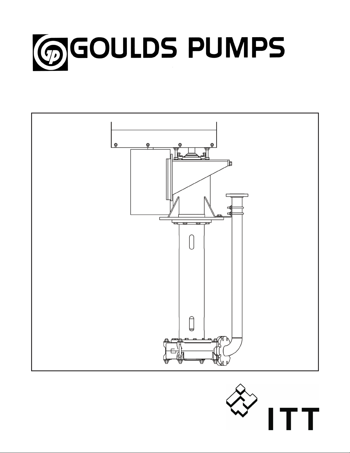
Model VRS
Page 2

2 VRS IOM - 5/08
Page 3

FORWORD
This manual provides instructions on the Installation, Operation, and Maintenance of the Goulds Model VRS Rubber Lined
Vertical Cantilever Pump. This manual covers the standard product plus common options that are available. For special
options, supplemental instructions are supplied. You must read and understand this manual before installing the VRS.
The design, materials, and workmanship incorporated in the construction of Goulds pumps makes them capable of giving
long, trouble-free service. The life and satisfactory service of any mechanical unit, however, is enhanced and extended by
correct application, proper installation, periodic inspection, condition monitoring, and careful maintenance. This instruction
manual was prepared to assist operators in understanding the construction and the correct methods of installing, operating,
and maintaining these pumps.
Goulds will not accept responsibility for damage or delays caused by failure to observe the instructions for
Installation, Operation, and Maintenance contained in this manual.
Warranty is valid only when genuine Goulds parts are used.
Use of the equipment on a service other than stated in the order may nullify the warranty, unless written approval is obtained
in advance from Goulds Pumps, Inc.
To assure proper installation, supervision from an authorized manufacturer’s representative is recommended.
Additional manuals can be obtained by contacting your local Goulds representative.
THIS MANUAL EXPLAINS
Proper Installation
n
Start-up Procedures
n
Operating Procedures
n
Routine Maintenance
n
Pump Overhaul
n
Trouble Shooting
n
Ordering Spares or Repair Parts
n
VRS IOM - 5/08 3
Page 4

4 VRS IOM - 5/08
Page 5

TABLE OF CONTENTS
PAGE SECTION
7 SAFETY
9 GENERAL INFORMATION
11 INSTALLATION
17 OPERATION
19 PREVENTIVE MAINTENANCE
23 DISSASEMBLY AND REASSEMBLY
1
2
3
4
5
6
27 SPARE AND REPAIR PARTS
7
VRS IOM - 5/08 5
Page 6

6 VRS IOM - 5/08
Page 7

IMPORTANT SAFETY NOTICE
To: Our Valued Customers
User safety is a major focus in the design of our products. Following the precautions outlined in this
manual will minimize your risk of injury.
ITT Goulds pumps will provide safe, trouble-free service when properly installed, maintained, and
operated.
Safe installation, operation, and maintenance of ITT Goulds Pumps equipment are an essential end user
responsibility. This Pump Safety Manual identifies specific safety risks that must be considered at all
times during product life. Understanding and adhering to these safety warnings is mandatory to ensure
personnel, property, and/or the environment will not be harmed. Adherence to these warnings alone,
however, is not sufficient — it is anticipated that the end user will also comply with industry and corporate
safety standards. Identifying and eliminating unsafe installation, operating and maintenance practices is
the responsibility of all individuals involved in the installation, operation, and maintenance of industrial
equipment.
Please take the time to review and understand the safe installation, operation, and maintenance guidelines
outlined in this Pump Safety Manual and the Instruction, Operation, and Maintenance (IOM) manual.
Current manuals are available at
your nearest Goulds Pumps sales representative.
www.gouldspumps.com/literature_ioms.html or by contacting
These manuals must be read and understood before installation and star t-up.
For additional information, contact your nearest Goulds Pumps sales representative or visit our Web site at
www.gouldspumps.com.
S-1
Page 8
SAFETY WARNINGS
Specific to pumping equipment, significant risks bear reinforcement above and beyond normal safety precautions.
WARNING
A pump is a pressure vessel with rotating parts that can be hazard o us. An y press ure vessel can explode,
rupture, or discharge its contents if sufficiently ove r press u r i zed causi n g deat h, personal injury, property
damage, and/or damage to the environment. All necessary measures must be taken to ensure over
pressurization does not occur.
WARNING
Operation of any pumping system with a blocked suction and discharge must be avoided in all cases.
Operation, even for a brief period under these conditions, can cause superheating of enclosed pumpage and
result in a violent explosion. All necessary measures must be taken by the end user to ensure this condition is
avoided.
WARNING
The pump may handle hazardous and/or toxic fluids. Care must be taken to identify the contents of the pump
and eliminate the possibility of exposure, particularly if hazardous and/or toxic. Potential hazards include, but
are not limited to, high temperature, flammable, acidic, caustic, explosive, and other risks.
WARNING
Pumping equipment Instruction, Operation, and Maintenance manuals clearly identify accepted methods for
disassembling pumping units. These methods must be adhered to. Specifically, applying heat to impellers
and/or impeller retaining devices to aid in their removal is strictly forbidden. Trapped liquid can rapidly
expand and result in a violent explosion and injury.
ITT Goulds Pumps will not accept responsibility for physical injury, damage, or delays caused by a failure to
observe the instructions for installation, operation, and maintenance contained in this Pump Safety Manual or the
current IOM available at www.gouldspumps.com/literature.
S-2
Page 9

SAFETY
DEFINITIONS
Throughout this manual the words WARNING, CAUTION, ELECTRICAL, and ATEX are used to indicate
where special operator attention is required.
Observe all Cautions and Warnings highlighted in this Pump Safety Manual and the IOM provided with
your equipment.
WARNING
Indicates a hazardous situation which, if not avoided, could result in death or serious injury.
Example:
Pump shall never be operated without coupling guard installed correctly.
CAUTION
Indicates a hazardous situation which, if not avoi ded, could result in minor or moderate injury.
Example: Throttling flow from the suction side may cause cavitation and pump damage.
ELECTRICAL HAZARD
Indicates the possibility of electrical risks if directions are not followed.
Example: Lock out driver power to prevent electric shock, accidental start-up, and physical injury.
When installed in potentially explosive atmospheres, the instructions that follow the Ex symbol must be
followed. Personal injury and/or equipment damage may occur if these instructions are not followed. If there
is any question regarding these requirements or if the equipment is to be modified, please contact an ITT
Goulds Pumps representative before proceeding.
Example:
parts, resulting in a spark and heat generation.
Improper impeller adjustment could cause contact between the rotating and stationary
S-3
Page 10

GENERAL PRECAUTIONS
WARNING
A pump is a pressure vessel with rotating parts that can be hazardous. Hazardous fluids may be contained by the
pump including high temperature, flammable, acidic, caustic, explosive, and other risks. Operators and
maintenance personnel must realize this and follow safety measures. Personal injuries will result if procedures
outlined in this manual are not followed. ITT Goulds Pumps will not accept responsibility for physical injury,
damage or delays caused by a failure to observe the instructions in this manual and the IOM provided with your
equipment.
WARNING
WARNING
General Precautions
NEVER use heat to disassemble pump due to risk of explosion from tapped liquid.
NEVER APPLY HEAT TO REMOVE IMPELLER. It may explode due to
trapped liquid.
WARNING
WARNING
WARNING
WARNING
WARNING
WARNING
WARNING
WARNING
WARNING
NEVER operate pump without safety devices installed.
NEVER operate pump without coupling guard correctly installed.
NEVER run pump below recommended minimum flow when dry, or without
prime.
ALWAYS lock out power to the driver befo re per fo rming pump maintenance.
NEVER operate pump with discharge valve closed.
NEVER operate pump with suction valve closed.
DO NOT change service application without approval of an authorized ITT
Goulds Pumps representative.
Safety Apparel:
Insulated work gloves when handling hot bearings or using bearing heater
Heavy work gloves when handling parts with shar p ed ges, especially
impellers
Safety glasses (with side shields) for eye protection
Steel-toed shoes for foot protection when handling parts, heavy tools, etc.
Other personal protective equipment to protect against hazardous/toxic fluids
Receiving:
Assembled pumping units and their components are heavy. Failure to properly lift
and support equipment can result in serious physical injury and/or equipment
damage. Lift equipment only at specifically identified lifting points or as
instructed in the current IOM. Current manuals are available at
www.gouldspumps.com/literature_ioms.html or from your local ITT Goulds
Pumps sales representative. Note: Lifting devices (eyebolts, slings, spreaders, etc.)
must be rated, selected, and used for the entire load being lifted.
Alignment:
WARNING
Shaft alignment procedures must be followed to prevent catastrophic failure of
drive components or unintended contact of rotating parts. Follow coupling
manufacturer’s coupling installation and operation procedures.
S-4
Page 11

WARNING
CAUTION
General Precautions
Before beginning any alignment procedure, make sure driver power is locked out.
Failure to lock out driver power will result in serious physical injury.
Piping:
Never draw piping into place by forcing at the flan ged con necti on s of t he pump.
This may impose dangerous strains on the unit and cause misalignment between
pump and driver. Pipe strain will adversely effect the operation of the pump
resulting in physical injury and damage to the equipment.
WARNING
WARNING
WARNING
WARNING
WARNING
WARNING
WARNING
WARNING
WARNING
WARNING
WARNING
CAUTION
CAUTION
WARNING
Flanged Connections:
Use only fasteners of the proper size and material.
Replace all corroded fasteners.
Ensure all fasteners are properly tightened and there are no missing fasteners.
Startup and Operation:
When installing in a potentially explosive environment, please ensure that the
motor is properly certified.
Operating pump in reverse rotation may result in contact of metal parts, heat
generation, and breach of containment.
Lock out driver power to prevent accidental start-up and physical injury.
The impeller clearance setting procedure must be followed. Improperly setting
the clearance or not following any of the proper procedures can result in sparks,
unexpected heat generation and equipment damage.
If using a cartridge mechanical seal, the centering clips must be installed and set
screws loosened prior to setting impeller clearance. Failure to do so could result
in sparks, heat generation, and mechanical seal damage.
The coupling used in an ATEX classified environment must be properly certified
and must be constructed from a non-sparking material.
Never operate a pump without coupling guard properly installed. Personal injury
will occur if pump is run without coupling guard.
Make sure to properly lubricate the bearings. Failure to do so may result in excess
heat generation, sparks, and / or premature failure.
The mechanical seal used in an ATEX classified environment must be properly
certified. Prior to start up, ensure all points of potential leakage of process fluid to
the work environment are closed.
Never operate the pump without liquid supplied to mechanical seal. Running a
mechanical seal dry, even for a few seconds, can cause seal damage and must be
avoided. Physical injury can occur if mechanical seal fails.
Never attempt to replace packing until the driver is properly locked out and the
coupling spacer is removed.
WARNING
WARNING
S-5
Dynamic seals are not allowed in an ATEX classified environment.
DO NOT operate pump below minimum rated flows or with suction and/or
discharge valve closed. These conditions may create an explosive hazard due to
vaporization of pumpage and can quickly lead to pump failure and physical injury.
Page 12

WARNING
WARNING
WARNING
WARNING
WARNING
CAUTION
CAUTION
WARNING
CAUTION
CAUTION
General Precautions
Ensure pump is isolated from system and pressure is relieved before
disassembling pump, removing plu gs, ope ni n g vent or drain valves, or
disconnecting piping.
Shutdown, Disassembly, and Reassembly:
Pump components can be heavy. Proper methods of lifting must be employed to
avoid physical injury and/or equipment damage. Steel toed shoes must be worn at
all times.
The pump may handle hazardous and/or toxic fluids. Observe proper
decontamination procedures. Proper personal protective equipment should be
worn. Precautions must be taken to prevent physical injury. Pumpage must be
handled and disposed of in conformance with applicable environmental
regulations.
Operator must be aware of pumpage and safety precautions to prevent physical
injury.
Lock out driver power to prevent accidental startup and physical injury.
Allow all system and pump components to cool before handling them to prevent
physical injury.
If pump is a Model NM3171, NM3196, 3198, 3298, V3298, SP3298, 4150, 4550,
or 3107, there may be a risk of static electric discharge from plastic parts that are
not properly grounded. If pumped fluid is non-conductive, pump should be
drained and flushed with a conductive fluid under conditions that will not allow
for a spark to be released to the atmosphere.
Never apply heat to remove an impeller. The use of heat may cause an explosion
due to trapped fluid, resulting in severe physical injury and property damage.
Wear heavy work gloves when handling impellers as sharp edges may cause
physical injury.
Wear insulated gloves when using a bearing heater. Bearings will get hot and can
cause physical injury.
S-6
Page 13

ATEX CONSIDERATIONS and INTENDED USE
Special care must be taken in potentially explosive environments to ensure that the equipment is properly
maintained. This includes but is not limited to:
1. Monitoring the pump frame and liquid end temperature.
2. Maintaining proper bearing lubrication.
3. Ensuring that the pump is operated in the intended hydraulic range.
The ATEX conformance is only applicable when the pump unit is operated within its intended use. Operating,
installing or maintaining the pump unit in any way that is not covered in the Instruction, Operation, and
Maintenance manual (IOM) can cause serious personal injury or damage to the equipment. This includes any
modification to the equipment or use of parts not provided by ITT Goulds Pumps. If there is any question
regarding the intended use of the equipment, please contact an ITT Goulds represe ntative before proceeding.
Current IOMs are available at
Pumps Sales representative.
All pumping unit (pump, seal, coupling, motor and pump accessories) certified for use in an ATEX classified
environment, are identified by an ATEX tag secured to the pump or the baseplate on which it is mounted. A
typical tag would look like this:
www.gouldspumps.com/literature_ioms.html or from your local ITT Goulds
The CE and the Ex designate the ATEX compliance. The code directly below these symbols reads as follows:
II = Group 2
2 = Category 2
G/D = Gas and Dust present
T4 = Temperature class, can be T1 to T6 (see Table 1)
Table 1
Max permissible
surface temperature
Code
T1 842 (450) 700 (372)
T2 572 (300) 530 (277)
T3 392 (200) 350 (177)
T4 275 (135) 235 (113)
T5 212 (100) Option not available
T6 185 (85) Option not available
o
F (oC)
The code classification marked on the equipment must be in accordance with the specified area where the
equipment will be installed. If it is not, do not operate the equipment and contact your ITT Goulds Pumps sales
representative before proceeding.
Max permissible
liquid temperature
o
F (oC)
S-7
Page 14

PARTS
The use of genuine Goulds parts will provide the safest and
most reliable operation of your pump. ITT Goulds Pumps ISO
certification and quality control procedures ensure the parts are
manufactured to the highest quality and safety levels.
Please contact your local Goulds representative for details on
genuine Goulds parts.
S-8
Page 15

GENERAL INFORMATION
GENERAL ..........................................9
PUMP DESCRIPTION ...................................9
NAMEPLATE INFORMATION .............................10
RECEIVING THE PUMP .................................10
Storage Requirements ................................10
Handling .......................................10
GENERAL
2
Keep this instruction manual handy for reference. Further
information can be obtained by contacting Goulds Pumps,
Ashland Operations, 500 East Centre St., Ashland, PA
17921 or your local representative.
Goulds Pumps will not be liable for any damages or delay
caused by failure to comply with the provisions of this
instruction manual. This pump is not to be operated at
PUMP DESCRIPTION
The Model VRS pump is a rubber lined vertical cantilever
centrifugal pump. The wet end of the pump contains the
same casing halves, liners, and impeller as a similar size
Model SRL pump.
The impeller is threaded onto the shaft. It is axially
adjustable by means of jacking bolts in the thrust housing
to renew and maintain proper leakage path clearances.
speeds, working pressures, discharge pressures, or
temperatures, nor used on liquids other than stated in the
original order acknowledgment without written permission
of Goulds Pumps.
The heavy duty bearing frame is made of cast iron and
contains a deep groove ball bearing on the inboard side and
an angular contact ball bearing on the outboard side. All
bearings are grease lubricated through fittings on the
bearing frame. The direction of rotation is clockwise when
viewed from the power end to the wet end.
VRS IOM - 5/08
9
Page 16

NAMEPLATE INFORMATION
Every pump has a nameplate that provides information about the pump. The nameplate is located on the bearing frame and
provides information about the pump’s hydraulic characteristics.
Figure 1
Goulds Pumps Nameplate
RECEIVING THE PUMP
Inspect the pump as soon as it arrives. Carefully check that
everything is in good order. Make notes of damaged or
missing items on the receipt and freight bill. File any claims
with the transportation company as soon as possible.
STORAGE REQUIREMENTS
Short Term: (Less than 6 months) Goulds normal
packaging procedure is designed to protect the pump
during shipping in covered trucks and during covered
storage. Upon receipt, store in covered and dry location.
10 VRS IOM - 5/08
Long Term: (More than 6 months) Requires special
precautions. Preservative treatment is applied to bearings
and machined surfaces. Rotate shaft several times every 30
days. Contact driver, coupling and mechanical seal
manufacturers for long term storage procedures.
HANDLING
Use care when moving pump. Lifting equipment must be
able to adequately support the entire assembly.
Page 17

INSTALLATION
SITE/FOUNDATION....................................11
SUMP ............................................11
LEVEL THE PUMP ....................................12
ALIGNMENT PROCEDURE ...............................12
Alignment Checks ..................................12
V-Belt Drive Pumps .................................12
Direct Connect Pumps ................................13
Alignment Criteria ................................13
SetUp.......................................13
Measurement Techniques ............................13
Angular Alignment ................................13
Method 1 - Dial Indicator Method ......................14
Method 2 - Feeler Gauge Method ......................14
Parallel Alignment ................................14
Method 1 - Dial Indicator Method ......................14
Method 2 - Straight Edge Method ......................14
Factors That May Disturb Alignment ......................14
PIPING............................................15
General ........................................15
Final Piping Check ..................................15
3
SITE/FOUNDATION
A pump should be located near the supply of liquid in a
clean dry area free from flooding. The area should provide
adequate space for operation, maintenance, and inspection,
considering complete disassembly and handling of
equipment.
The pump support must be sufficiently substantial and level
to give rigid support to the pump and absorb vibration.
SUMP
The sump must be screened to prevent any foreign objects
from falling into the sump and damaging the pump. The
openings in the screening should be smaller than the
openings in the pump impeller. Guidelines for sump design
can be found in the Hydraulic Institute Standards for sump
design.
The location and size of the mounting holes are shown on
the outline assembly drawing supplied with the pump
order. The bolts which secure the pump to the foundation
should be 1/8” less in diameter than the hole size.
VRS IOM - 5/08
11
Page 18

LEVEL THE PUMP
Leveling the pump is best performed without the drive and
motor installed. Loosen the (4) bearing frame hold down
bolts. Level the bearing housing to within 0.010 in.
(0.25 mm). Place shims between bearing housing and
support so that a gap of no more than 0.002 in (0.05 mm)
exists at any of the (4) anchor bolts when the bolts are
ALIGNMENT PROCEDURE
! WARNING
s
Before beginning any alignment procedur, make sure
driver power is locked out.
Check the alignment twice:
Initial Alignment is done prior to operation when the
•
pump and driver are at ambient temperature.
Final Alignment is done just after operation when the
•
pump and driver are at operating temperature.
NOTE: Proper alignment is the responsibility of the
installer and user of the unit.
Accurate alignment of the equipment must be attained.
Trouble free operation can be accomplished by following
these procedures.
ALIGNMENT CHECKS
Initial Alignment (Cold Alignment)
loose. Tighten the anchor bolts. If a floorplate is used, shim
each anchor bolt location so that a gap of no more than
0.002 in (0.05mm) exists at any of the anchor bolt locations
when the bolts are loose.
Final Alignment (Hot Alignment)
After First Run - To obtain correct alignment when both
pump and driver are at operating temperature. Thereafter,
alignment should be checked periodically in accordance
with plant operating procedures.
V-BELT DRIVE PUMPS
! WARNING
s
Before beginning any alignment procedure, make sure
driver power is locked out.
1. Place a straight edge across the top of the motor and
pump sheaves to measure the angular and parallel
misalignment (see Figure 2). Measure the gap between
the straight edge and the sheaves with feeler gauges. If
the gap exceeds 0.010 in (0.25 mm), adjust the sheaves
along the shafts to correct parallel misalignment and
shim the motor to correct angular misalignment.
2. A dial indicator can be used to check runout on the
periphery and face of each sheave.
Before Connecting Piping - To be sure alignment can be
•
obtained.
After Connecting Piping - To ensure pipe strains have
•
not altered alignment. If changes have occurred, alter
piping to remove pipe strains on pump flanges.
Angular Misalignment Parallel Misalignment Perfect Alignment
Figure 2
V-Belt Drive Alignment
12 VRS IOM - 5/08
Page 19

DIRECT CONNECT PUMPS
ALIGNMENT CRITERIA
Disconnect coupling halves before proceeding with the
alignment. Check for parallel and angular alignment with
either the Dial Indicator Method or the Straight Edge
Method outlined below.
The faces and outside diameters of the coupling halves
must be square and concentric with the bores. Good
alignment is achieved when the dial indicator readings for
both parallel and angular misalignment are 0.003 in
(0.076 mm) total indicator reading (TIR) or less when the
pump and driver are at operating temperature (see Final
Alignment). Figure 3 provides a representation of what to
look for.
Figure 4
Dial Indicator Setup
3
Angular
Misalignment
Direct Connect Alignment
SET UP
! WARNING
s
Before beginning any alignment procedure, make sure
driver power is locked out.
1. Mount two dial indicators on one of the coupling
halves (X) so that they contact the other coupling half
(Y) as shown in Figure 4.
2. Check setting of indicators by rotating coupling half X
to ensure indicators stay in contact with coupling half
Y but do not bottom out. Adjust indicators
accordingly.
Parallel
Misalignment
Figure 3
Perfect
Alignment
Figure 5
Directions of viewing coupling
from top of pump
MEASUREMENT TECHNIQUES
1. To ensure accuracy of indicator readings, always rotate
both coupling halves together so indicators contact the
same point on coupling half Y. This will eliminate any
measurement problems due to runout on coupling half
Y.
2. Take indicator measurements with driver hold down
bolts tightened. Loosen hold down bolts prior to
making alignment corrections.
3. Take care not to damage indicators when moving
driver during alignment corrections.
VRS IOM - 5/08
ANGULAR ALIGNMENT
A unit is in angular alignment when indicator A (Angular
Indicator), Figure 3, does not vary by more than 0.003 in
(0.076 mm) as measured at four points on the coupling
periphery 90 degrees apart at operating temperature. There
are two methods outlined below which are acceptable to
achieve alignment.
13
Page 20

METHOD 1 - DIAL INDICATOR METHOD
METHOD 1 - DIAL INDICATOR METHOD
For the following steps, refer to Figure 5.
1. Zero indicator A at position 1 of coupling half Y. Mark
this position on both flanges.
2. Rotate both flanges 180 degrees to position 3. Observe
needle and record reading.
3. Negative Reading - The coupling halves are further
apart at position 3 than position 1.
Positive Reading - The coupling halves are closer at
position 3 than position 1.
4. The angular alignment should not be a problem. If,
however, 0.003 in (0.076 mm) TIR or less is not
attainable, check the motor and motor mount for
perpendicularity to their respective centerlines.
5. Repeat steps 1 through 4 substituting position 2 for
position 1 and position 4 for position 3. Use the same
marks made on the coupling from position 1 and be
sure to turn the coupling halves together.
METHOD 2 - FEELER GAUGE METHOD
For the following steps refer to Figure 5.
1. Insert a feeler gauge at position 1 at the periphery of
the couplings. Mark this position on both flanges.
2. Record the largest gauge size which fits snugly
between the two flanges.
3. Rotate both flanges 180 degrees to position 3.
4. Insert a feeler gauge at position 3 at the periphery of
the couplings.
5. Record the largest gauge size which fits snugly
between the two flanges.
6. Calculate the difference between the readings at
positions 1 and 3. The difference should not be greater
than 0.003 in (0.076 mm). If, however, 0.003 in (0.076
mm) TIR or less is not attainable, check the motor and
motor mount for perpendicularity to their respective
centerlines.
7. Repeat steps 1 through 6 substituting position 2 for
position 1 and position 4 for position 3. Use the same
marks made on the coupling from position 1 and be
sure to turn the coupling halves together.
PARALLEL ALIGNMENT
The unit is in parallel alignment when indicator P (Parallel
Indicator, see Figure 4) does not vary by more than 0.003
in (0.076 mm) as measured at four points on the coupling
periphery 90 degrees apart at operating temperature. There
are two methods outlined below which are acceptable to
achieve alignment.
For the following steps, refer to Figure 5.
1. Zero indicator P at position 1 of coupling half Y. Mark
this position on both flanges.
2. Rotate both flanges 180 degrees to position 3. Observe
the needle and record the reading.
3. Negative Reading - The coupling half Y is shifted
toward position 1. If the value is greater than 0.003 in
(0.076 mm), shift the motor accordingly.
Positive Reading - The coupling half Y is shifted toward
position 3. If the value is greater than 0.003 in (0.076 mm),
shift the motor accordingly.
4. Repeat steps 1 through 3 until indicator P reads 0.003
in (0.076 mm) or less.
5. Once ideal alignment is reached, repeat steps 1 through
4 substituting position 2 for position 1 and position 4
for position 3.
METHOD 2 - STRAIGHT EDGE METHOD
For the following steps, refer to Figure 5.
1. Place a straight edge across the two coupling flanges at
position 1 and mark this position on both flanges.
2. Adjust the motor so that the straight edge rests evenly
on both flanges within 0.003 in (0.076 mm).
3. Rotate both flanges to position 2 and repeat steps 1 and
2.
4. The unit will be in parallel alignment when the straight
edge rests evenly within 0.003 in (0.076 mm) on the
coupling periphery at both positions along the
periphery.
NOTE: Care must be taken to have the straight edge
parallel to the axis of the shafts.
TIP: Since the coupling halves are disconnected, this would
be a good time to check the direction of motor rotation.
FACTORS THAT MAY AFFECT
ALIGNMENT
$
The unit should be checked periodically for alignment.
If the unit does not stay aligned after being properly
installed, it may be due to any of the following causes:
1. Non-rigid foundation
2. Foundation settling
3. Bearing wear
CAUTION
14 VRS IOM - 5/08
Page 21

4. Distortion due to piping loads/strain
5. Distortion of support due to an adjacent heat source
6. Structural changes due to variable loading or other
causes
7. Loose nuts/bolts on the pump and/or drive assembly
PIPING
GENERAL
Review the guidelines for piping in the ‘Hydraulic Institute
Standards’ prior to pump installation.
1. All piping must be supported independently of, and
line up naturally with, the pump flanges.
$
Never draw piping into place by forcing the flanged
connections of the pump. This may impose dangerous
strains on the unit and cause misalignment between
pump and driver. Pipe strain will adversely affect the
reliability of the pump.
2. Piping runs should be as short as possible to minimize
friction losses.
3. Arrangements should be made to keep the pump from
back spinning severely during shutdown. In situations
where this occurs, a non-slam check valve should be
installed.
$
Do not start the pump while the impeller is in reverse
rotation.
CAUTION
CAUTION
FINAL PIPING CHECK
After Connecting the Piping to Pump:
1. Turn the shaft several times by hand to confirm free
rotation.
2. Check alignment per the procedure outlined earlier. If
pipe strain is affecting alignment, it must be corrected
prior to startup.
3
VRS IOM - 5/08
15
Page 22

16 VRS IOM - 5/08
Page 23

OPERATION
PREPARATION FOR START-UP ............................17
Pump Support.....................................17
Bearing Lubrication .................................17
Shaft Rotation ....................................17
Correct Driver Rotation ...............................17
Priming ........................................17
START THE PUMP ....................................18
RUNNING PUMP......................................18
General Considerations................................18
Operating At Reduced Capacity ...........................18
Final Alignment ...................................18
PREPARATION FOR START-UP
4
PUMP SUPPORT
Before starting a newly installed pump, check the pump
supports and piping to be certain that they conform to the
specifications in the ‘Installation’ section of this manual.
BEARING LUBRICATION
The bearings must have adequate lubrication. The bearings
were properly filled with grease prior to shipment.
Regrease bearings if pump was disassembled. Refer to the
Maintenance of Bearings section.
SHAFT ROTATION
The pump shaft must turn without any binding or rubbing only the uniform frictional drag of the bearings should be
felt. If the pump does not turn freely by hand, check to
determine the cause of the binding.
CORRECT DRIVER ROTATION
$
Incorrect rotation could result in considerable damage
to the pump. Check the motor rotation when motor is
not connected to the pump shaft.
The direction of rotation of the driver must be checked
before it can be coupled to the pump. The correct direction
of rotation of the pump is indicated on the bearing frame.
Since the impeller is threaded on, reverse rotation could
cause the impeller to unscrew from the shaft.
CAUTION
! WARNING
s
Lock out driver power to prevent accidental start-up
when working on drive.
1. Lock out power to driver.
2. Disconnect coupling from the driver or the belts from
the drive. Make sure no parts are loose.
3. Unlock driver power.
4. Make sure everyone is clear of driver. Jog the driver
just long enough to determine the direction of rotation.
Rotation must correspond to the arrow on the pump.
5. Lockout power to driver and reinstall coupling or
belts.
6. Reinstall coupling or belt drive guard.
PRIMING
The liquid level must be above that shown on the
dimensional drawing supplied with the order.
VRS IOM - 5/08
17
Page 24

START THE PUMP
! WARNING
s
This unit must never be used without proper
installation of the safety guards for rotating parts.
1. Make sure the liquid level is at or above the minimum.
2. Slightly open the discharge valve.
3. Start driver.
RUNNING PUMP
GENERAL CONSIDERATIONS
Driver may overload if the pumpage specific gravity
(density) is greater than originally assumed or the rated
flow rate is exceeded.
Always operate the pump at or near the rated conditions to
prevent damage resulting from cavitation or recirculation.
New bearing housing seals may generate some heat until
broken in. Oil should be applied to them if heat becomes
excessive.
OPERATING AT REDUCED
CAPACITY
$
Immediately observe the discharge gauge after starting
pump. If discharge pressure is not quickly obtained,
stop the driver, check the liquid level and discharge
valve, and attempt to restart.
4. Slowly open the discharge valve.
2. Increased Radial Thrust - Stresses on shaft and
bearings.
3. Heat Build Up - Vaporization causing rotating parts to
score or seize or possible explosion.
CAUTION
FINAL ALIGNMENT
1. Run the pump under actual conditions for a sufficient
length of time to bring the pump and driver up to
operating temperature.
2. Check the alignment per alignment procedure outlined
earlier.
! WARNING
s
Do NOT operate pump below minimum rated flows or
with the discharge valve closed. These conditions can
quickly lead to pump failure and a possible explosion.
Damage caused by reduced flow operations includes:
1. Increased Vibration Levels - Affects bearings.
18 VRS IOM - 5/08
Page 25

PREVENTIVE MAINTENANCE
GENERAL COMMENTS .................................19
MAINTENANCE SCHEDULE ..............................19
Routine Maintenance .................................19
Routine Inspections..................................19
Quarterly Inspections .................................19
Yearly Inspections ..................................19
MAINTENANCE OF BEARINGS ............................20
MAINTENANCE OF SEALS ...............................20
MAINTENANCE OF DRIVE ...............................20
IMPELLER CLEARANCE SETTING ..........................21
PUMP WASHDOWN....................................21
TROUBLESHOOTING GUIDE ..............................21
GENERAL COMMENTS
A routine maintenance program can extend the life of your
pump. Well maintained equipment will last longer and
require fewer repairs. A maintenance record will help
identify the potential causes of problems.
MAINTENANCE SCHEDULE
Routine Maintenance
Bearing Lubrication
•
Vibration Analysis
•
Routine Inspections
Check for unusual noise, vibration and bearing
•
temperature
Inspect pump and piping for leaks
•
Check temperature of bearings
•
Observe discharge pressure
•
Quarterly Inspections
Check hold down bolts for tightness
•
Yearly Inspections
Check pump capacity, pressure, and power. If the
•
pump performance does not satisfy your process
requirements, the pump should be disassembled and
inspected. Worn parts should be replaced.
5
VRS IOM - 5/08
19
Page 26

MAINTENANCE OF BEARINGS
The bearings have been adequately greased prior to
shipment. Under normal operating conditions, add grease
monthly or after 500 operating hours, whichever occurs
first. Add approximately (4) pumps to the inboard fitting
and outboard fitting. Use a lithium based NLGI 2 grease to
match the type used when the pump was initially built.
$
Never mix greases of different consistency (NLGI 1 or
3 with NLGI 2) or different thickener soaps (sodium or
calcium with lithium). The consistency usually
becomes softer and will not provide adequate
lubrication to the bearings.
CAUTION
MAINTENANCE OF SEALS
When it becomes necessary to replace the bearing housing
seals, the housing and the bearings should be flushed clean
with a solvent and repacked with new grease. Overpacking
results in excessive bearing temperature.
NOTE: When regreasing there is a possibility of
impurities entering the bearing housing. The grease
container, the greasing device, and the fittings must be
clean.
Acceptable Greases:
Shell Alvania No. 2
Mobil Mobilux EP No. 2
Texaco Multifak No. 2
Sun Oil Co. Prestige No. 42
American Oil Co. Amolith Grease No. 2
MAINTENANCE OF DRIVE
Well designed and properly installed V-belt drives are
capable of running for years without maintenance. There
are a few points that should be checked periodically.
Sheave Alignment - Alignment must be maintained
•
for full power transmission, minimum vibration, and
long drive life.
Belt Installation - When installing new belts, shorten
•
the center distance between sheaves so that the belts
can be placed on the sheave without the use of force.
Never ‘roll’ or ‘pry’ the belts into place, as this could
damage the belt cords.
Check Belt Fit - Regardless of the belt section used,
•
the belt should never be allowed to bottom in the
groove. This will cause the belts to lose their wedging
action and allow slippage. Replace such sheaves or
belts.
Maintain Proper Belt Tension - Tension is essential
•
for long belt life. Improper tension could cause belt
fatigue and/or hot bearings. Methods of determining
proper belt tension can be obtained from the drive
manufacturer.
Use Belt Guards - Belt guards protect personnel from
•
danger and the drive from contamination. Inspect
periodically to assure that belts do not rub against
guard.
Keep Belts Clean - Dirt and grease reduce belt life.
•
Belt dressing affects performance only temporarily
and is never recommended. Maintaining a clean drive
is a better idea.
If any questions arise pertaining to the drive limitations,
consult the manufacturer.
20 VRS IOM - 5/08
Page 27

IMPELLER CLEARANCE SETTING
A change in pump performance may be noted over time by
a drop in head or flow or an increase in power required.
Performance can usually be restored by adjusting the
impeller clearance. Each application is different and hence
it is necessary to monitor the amount of wear over a certain
period of time in order to set up an adjustment schedule.
Other factors which may indicate that impeller adjustment
is required are:
High thrust bearing temperatures resulting from
•
uneven adjustment of impeller adjusting bolts
Noise and vibration resulting from the impeller
•
rubbing the suction liner
Adjust the impeller clearance with the pump in the vertical
position.
! WARNING
s
Lockout driver power to prevent accidental start-up.
1. Lockout power to driver.
2. Remove the coupling guard (direct drive) or belt guard
(belt drive).
3. “Break” the coupling (direct drive) or remove tension
from belts (belt drive).
NOTE: Lubricate the adjusting bolts and nuts for easy
turning.
4. Loosen the thrust housing adjusting bolt nuts (415A)
and locking capscrews (356B).
5. Turn thrust housing adjusting bolts (9956)
counterclockwise to lower the thrust housing (134A)
until the impeller (101) touches the suction liner
(600R).
6. Turn the thrust housing adjusting bolts (9956)
clockwise to raise the thrust housing (134A) 0.030 in
(0.76 mm), which is the recommended operating
clearance. This adjustment is best measured with a dial
indicator. Adjust each bolt slightly each time around so
that the thrust housing rises evenly and is not cocked
in the bearing frame (228). Make sure the rotating
assembly turns freely throughout the entire rotation.
7. Tighten the thrust housing adjusting bolt nuts (415A)
and locking capscrews (356B), carefully noting that
the dial indicator does not change during final
tightening.
8. Make sure the rotating assembly turns freely
throughout the entire rotation.
9. Align the coupling (direct drive) or sheaves (belt
drive) as outlined in the installation section.
10. Replace the coupling guard (direct drive) or belt guard
(belt drive).
5
PUMP WASHDOWN
The pump is designed to prevent liquid from entering the
bearing frame. Care should be taken, however, to avoid
spraying a high pressure stream directly at the bearing
frame seals.
TROUBLESHOOTING GUIDE
INSUFFICIENT CAPACITY
Pump not primed, check the sump liquid level
•
Speed too low
•
Total head higher than pump rating
•
Insufficient NPSH
•
Impeller passages partially blocked.
•
Wrong direction of rotation
•
Mechanical defects: impeller worn or damaged,
•
defective gasket causing leakage
INSUFFICIENT PRESSURE
Speed too low
•
Air in liquid
•
Wrong direction of rotation
•
Mechanical defects: impeller worn or damaged,
•
defective gasket causing leakage
VRS IOM - 5/08
21
Page 28

MOTOR OVERLOAD
Speed too high
•
Total head lower than pump rating resulting in
•
increased flow
Liquid being pumped has higher specific gravity than
•
that for which it is rated
Mechanical defects: bent shaft, worn bearings, worn
•
impeller or other wet end parts
Solids locked in and around impeller
•
Rubbing or binding of rotating elements
•
PUMP VIBRATION
Foundation not sufficiently rigid
•
Impeller partially blocked causing imbalance
•
Misalignment of thrust housing - housing cocked
•
Mechanical defects: bent shaft, worn bearings, worn
•
impeller
WATER HAMMER
Water hammer is a high pressure surge within a closed pipe
system, created by a rapid change in the flowrate. The most
common is the sudden opening or closing of a valve or
other flow control device. Rapid changes in flowrate can
also occur when there is a sudden change in pump speed.
Extensive damage to the pump and pipeline can result from
water hammer.
22 VRS IOM - 5/08
Page 29

DISASSEMBLY AND REASSEMBLY
PUMP DISASSEMBLY ..................................23
Disassembly of Wet End ...............................23
Disassembly of Power End ..............................24
INSPECTIONS .......................................24
Impeller........................................24
Suction/Gland Liners .................................24
Casing ........................................24
Shaft .........................................24
Column Pipe.....................................24
Bearings .......................................24
Seals, O-Rings, Gaskets ...............................24
REASSEMBLY .......................................25
Reassembly of Power End ..............................25
Reassembly of Wet End ...............................25
Reassembly of Drive .................................25
REFER TO FIGURES AT END OF MANUAL FOR DISASSEMBLY AND REASSEMBLY.
PUMP DISASSEMBLY
DISASSEMBLY OF WET END
! WARNING
s
Lockout driver power to prevent accidental startup.
1. Lockout power supply to motor.
2. Close discharge valve. Drain the pump.
! WARNING
s
The pump may handle hazardous and/or toxic fluids.
Hazardous fluids may be under pressure and may erupt
when pump is opened, particularly if pump is hot.
Allow pump to cool and open cautiously. Skin and eye
protection may be required. Precautions must be taken
to prevent injury or environmental damage. Always
know the contents of the pump prior to opening it.
Failure to do so can result in death, personal injury or
property or environmental damage.
3. Remove piping from pump.
4. Remove coupling guard (direct connect) or belt guard
and belts (belt drive). Remove motor.
5. Remove pump from sump and lay on horizontal
surface.
6. Wash down pump and inside column pipe and casing
with appropriate cleaner.
7. Remove motor mount and coupling (direct drive) or
sheave (belt drive) from the pump.
8. Remove strainer, and/or tailpipe from suction half
casing (100A), if supplied.
9. Remove the discharge pipe assembly (195) from
bearing frame (228) and casing (100A/D), if
applicable.
! WARNING
s
Suction casing (100A) must be supported before
removing tiebolts.
10. Remove the suction half casing (100A). The suction
liner (600R) will be attached to the casing.
11. Remove the suction liner (600R) from the suction half
casing (100A).
! WARNING
s
Do NOT apply heat to the hub or nose of the impeller
due to the danger of explosion.
12. Unscrew the impeller (101) from the shaft (122) by
clamping the shaft and turning the impeller in the
direction for a normal right hand thread (counterclockwise when viewing eye of impeller). After
removing impeller, wrap tape around shaft threads to
6
VRS IOM - 5/08
23
Page 30

avoid damage. Remove impeller washer (199).
13. Mark the orientation of the gland half casing (100D) to
the column pipe (192). Disassemble the gland half casing
from the column pipe by removing capscrews (371W).
The gland liner (600T) will be attached to the casing.
14. Remove the gland liner (600T) from the gland half
casing (100D).
15. Mark orientation of column pipe (192) to bearing
frame (228). Disassemble column pipe from bearing
frame by removing capscrews (371M).
DISASSEMBLY OF POWER END
1. Remove the inboard bearing deflector (123A) by
sliding it down the shaft.
2. Remove the inboard seal plate (119B) with O-ring
(412) and seal (333) from the bearing housing (228).
3. Remove thrust housing locking capscrews (356B).
4. Draw thrust housing (134A) and shaft (122) from
bearing frame (228).
5. Check inboard bearing (168C) to see if it is worn,
loose, or rough and noisy when rotated. Press the
inboard bearing (168C) off the shaft (122) if
replacement is required. It is recommended that a new
bearing be installed after pressing off old bearing,
regardless of condition. The thrust bearing must be
removed from the shaft to replace the inboard bearing
(see step 7).
6. Remove the outboard deflector (123) by sliding up the
shaft.
7. Remove the thrust bearing locking clip (361) from the
thrust housing (134A).
8. Slide thrust housing (134A) up the shaft to remove
from the thrust bearing (112C).
7. Check outboard thrust bearing (112C) to see if they are
worn, loose, or rough and noisy when rotated. Remove
the outboard bearing locknut (136) and lockwasher
(382). Press the outboard bearing (112C) off the shaft
if replacement is required. It is recommended that a
new bearing be installed after pressing off old bearing,
regardless of condition.
8. Check the condition of the inboard seal (333). Remove
the inboard seal from the inboard seal plate (119B) if
replacement is required. It is recommended that a new
seal be installed after pressing out old seal, regardless
of condition.
9. Check the condition of the outboard seal (332). Press
the outboard seal from the thrust housing (134A) if
replacement is required. It is recommended that a new
seal be installed after pressing out old seal, regardless
of condition.
INSPECTIONS
IMPELLER
Replace if excessive erosion, extreme wear, or vane
breakage is evident. Reduction in hydraulic performance
may be caused by excessive wear, especially along the
suction wear ring surface.
SUCTION/GLAND LINERS
Replace if excessive erosion or extreme wear is evident.
CASING
Replace if excessive erosion, corrosion, or extreme wear is
evident.
SHAFT
Check for runout [0.006 in (.015 mm) maximum] to ensure
that the shaft is not bent. Bearing seats and seal areas must
be smooth and free of scratches and grooves. Shaft threads
must be in good condition. Replace if necessary.
COLUMN PIPE
Replace if worn or excessively corroded.
BEARINGS
Replace if worn, loose, or rough and noisy when rotated.
SEALS, O-RINGS, GASKETS
Replace during reassembly.
24 VRS IOM - 5/08
Page 31

REASSEMBLY
REASSEMBLY OF POWER END
1. Clean shaft (122) thoroughly, checking for nicks or
worn areas.
2. Press the outboard seal (332) into the thrust housing
(134A), positioning the seal so that the lip points
upward when installed in the pump. Press the inboard
seal (333) into the inboard seal plate (119B),
positioning the seal so that the lip points downward
when installed in the pump. Lubricate both seals with a
thin coat of grease.
3. Heat the inboard bearing (168C) evenly using an oven,
bearing heater, or hot clean oil bath. The use of a torch
is not recommended. Heat the bearing to 230 degrees F
to 250 degrees F (110 degrees C to 121 degrees C).
Slide the bearing onto the shaft from the drive end
until the bearing shoulder is firmly against the shaft
shoulder. Hold in place until bearing cools and grips
the shaft.
4. Heat the outboard bearing (112C) evenly using an
oven, bearing heater, or hot clean oil bath. The use of a
torch is not recommended. Heat the bearing to 230
degrees F to 250 degrees F (110 degrees C to 121
degrees C). Slide the bearing onto the shaft until the
bearing shoulder is firmly against the shaft shoulder.
Hold in place until bearing cools and grips the shaft.
5. Position bearing lockwasher (382) and locknut (136)
against the bearing shoulder and tighten firmly. Bend
‘tang’ of lockwasher into locknut slot after the locknut
has been tightened.
6. Hand pack the inboard (168C) and outboard bearings
(112C) with recommended grease (see Maintenance
section). Mound a small amount of grease above the
bearing to ensure sufficient lubrication.
7. Insert thrust housing (134A) over the outboard bearing
(112C).
8. Insert bearing locking clip (361) in thrust housing
(134A).
9. Install O-ring (496A) on thrust housing (134A) and
lubricate.
10. Install outboard deflector (123) by sliding it down the
shaft until it is approximately 0.06 in (1.5 mm) from
the thrust housing (134A).
11. Insert thrust housing and shaft assembly into bearing
frame (228). Install thrust housing locking capscrews
(356B), thrust housing adjusting capscrews (9956) and
nuts (415A). Adjust all hardware so that the thrust
housing (134A) bottoms out in bearing frame (228).
12. Install O-ring (412) on inboard seal plate (119B). Slide
inboard seal plate and seal up shaft and mount to
bearing housing (228).
13. Install inboard deflector (123A) by sliding it up the
shaft until it is approximately 0.06 in (1.5 mm) from
the inboard seal plate (119B).
REASSEMBLY OF WET END
1. Slide column pipe (192) up shaft (122) and attach to
bearing frame (228) with capscrews (371M) using the
orientation marks made during disassembly.
2. Attach gland liner (600T) into gland half casing
(100D).
3. Attach gland half casing (100D) to column pipe (192)
using the orientation marks made during disassembly.
4. Remove protective tape from shaft (122) threads.
Install impeller washer (199) on shaft (122). Thread
the impeller (101) onto the shaft until it is snug against
the shaft washer (199). Hold the drive end of the shaft
and firmly tighten the impeller.
5. Move the impeller (101) by means of the thrust
housing adjusting capscrews (9956) toward the drive
end as far as possible.
6. Install the suction liner (600R) into the suction half
casing (100A).
7. Attach the suction half casing (100A) and liner to the
gland half casing (100D).
8. Adjust the impeller using the thrust housing adjusting
screws (9956) so that the impeller turns freely.
9. Assemble the discharge pipe assembly (195) to the
casing discharge (100A/D) and bearing frame, if
supplied.
10. Install strainer and/or tailpipe onto suction half casing
(100A), if supplied.
11. Install unit into sump, being careful not to damage the
strainer, if supplied.
12. Connect piping to pump following procedures in the
‘Installation’ section.
13. Use the impeller clearance setting procedure on page
18 to set proper impeller clearance.
REASSEMBLY OF DRIVE
1. Mount drive onto pump.
2. Align the coupling (direct drive) or sheaves (belt
drive) as outlined previously.
3. Replace the coupling guard (direct drive) or belt guard
(belt drive).
6
VRS IOM - 5/08
25
Page 32

26 VRS IOM - 5/08
Page 33

SPARE AND REPAIR PARTS
REPLACEMENT PARTS PROCEDURE ........................27
RECOMMENDED SPARE PARTS ............................27
REPLACEMENT PARTS PROCEDURE
To ensure against possible long and costly down time
periods, especially on critical services, it is advisable to
have spare parts on hand.
Repair orders will be handled with a minimum of delay if
the following directions are followed:
1. Give model number, size of pump, and serial number.
These can be obtained from the nameplate on the
pump.
RECOMMENDED SPARE PARTS
Light Duty - Random mildly abrasive particles
(1) Seal/Gasket Set
Medium Duty - Light slurries up to 1.2 SG with
moderately abrasive materials
(1) Impeller
(1) Gland Liner
(1) Suction Liner
(1) Seal/Gasket Set
(1) Set Bearings
2. Write plainly the name and part number of each part
required. These names and numbers should agree with
those on the bill of material.
3. Give the number of parts required.
4. Give complete shipping instructions.
Severe Duty - Key process equipment and/or heavy
slurries over 1.2 SG with high heads and highly abrasive
particles
(2) Impeller
(2) Gland Liner
(2) Suction Liner
(3) Seal/Gasket Set
(1) Spare Pump
7
Heavy Duty - Slurries over 1.2 SG with highly abrasive
materials
(1) Impeller
(1) Gland Liner
(1) Suction Liner
(1) Shaft/Bearing Assembly
(3) Seal/Gasket Set
VRS IOM - 5/08
27
Page 34

Figure 6
VRS Sectional
28 VRS IOM - 5/08
Page 35

Figure 7
VRS Wet End Assembly
7
VRS IOM - 5/08 29
Page 36

Figure 8
VRS Power End Assembly
30 VRS IOM - 5/08
Page 37

NOTES
7
VRS IOM - 5/08 31
Page 38

Page 39

Page 40

HOW TO ORDER PARTS
When ordering parts call
1-800-446-8537
or your local ITT Goulds Representative
EMERGENCY SERVICE
Emergency parts service is available
24 hours a day, 365 days/year
Call 1-800-446-8537
Visit our website at www.gouldspumps.com
Form No. IVRS Rev. 5/08
© copyright 2008 Goulds Pumps, Incorporated
a subsidiary of ITT Corporation.
 Loading...