

Goulds Pumps VIC User Manual
Goulds Pumps
T Design
L Type Alternate –
Suction in Barrel
Installation, Operation, and
Maintenance
Model VIC


Table of Contents
Introduction and Safety...................................................................................................................................................3
Safety...................................................................................................................................................................................3
Safety message levels.....................................................................................................................................................3
Environmental safety.....................................................................................................................................................4
User health and safety...................................................................................................................................................4
Safety regulations for Ex-approved products in potentially explosive atmospheres...........................................6
Product warranty...............................................................................................................................................................7
Transportation and Storage............................................................................................................................................8
Receive the unit..................................................................................................................................................................8
Unpack the unit.................................................................................................................................................................8
Pump handling...................................................................................................................................................................8
Lifting methods..............................................................................................................................................................8
Pump storage requirements...........................................................................................................................................10
Prepare the pump for long-term storage.................................................................................................................11
Product Description........................................................................................................................................................12
General description.........................................................................................................................................................12
Nameplate information..................................................................................................................................................12
Table of Contents
Installation.........................................................................................................................................................................15
Preinstallation...................................................................................................................................................................15
Inspect the barrel flange or sub-base........................................................................................................................15
Concrete foundation requirements...........................................................................................................................15
Install the pump on a structural-steel foundation...................................................................................................17
Piping checklists...........................................................................................................................................................17
Install a partially-assembled pump...............................................................................................................................18
Install the bowl assembly...............................................................................................................................................19
Install the threaded coupling.........................................................................................................................................20
Install the column ..........................................................................................................................................................20
Install the discharge head...............................................................................................................................................22
Stuffing box installation.................................................................................................................................................22
Install the type A and B stuffing boxes....................................................................................................................24
Install the type C stuffing box....................................................................................................................................25
Mechanical seal options..................................................................................................................................................25
Install the mechanical seal..........................................................................................................................................26
Assemble a single inside-mounted mechanical seal................................................................................................30
Assemble a single outside-mounted mechanical seal.............................................................................................31
Install the high-pressure seal......................................................................................................................................32
Install the dual mechanical seals................................................................................................................................33
Install a solid-shaft driver...............................................................................................................................................34
Install the coupling hub..............................................................................................................................................37
Impeller adjustment.....................................................................................................................................................37
Adjust the impeller for a solid-shaft driver..............................................................................................................39
Install a hollow-shaft driver...........................................................................................................................................39
Assemble the type AR rigid-flanged coupling.........................................................................................................41
Complete the hollow-shaft driver installation.........................................................................................................42
Adjust the impeller for a hollow-shaft driver..........................................................................................................43
Installation and startup checklist...................................................................................................................................44
Commissioning, Startup, Operation, and Shutdown............................................................................................46
Preparation for startup...................................................................................................................................................46
Model VIC Installation, Operation, and Maintenance 1

Table of Contents
Prepare for startup.......................................................................................................................................................46
Pump priming..................................................................................................................................................................47
Start the pump.................................................................................................................................................................47
Pump operation precautions.........................................................................................................................................48
Mechanical seal leaks......................................................................................................................................................48
Stuffing box leaks............................................................................................................................................................49
Shut down the pump......................................................................................................................................................49
Lubricate the thrust pot during a shutdown period...................................................................................................49
Maintenance......................................................................................................................................................................50
Maintenance schedule.....................................................................................................................................................50
Packing adjustment and replacement...........................................................................................................................50
Adjust the packing when leaking is excessive..........................................................................................................51
Adjust the packing when there is overheating or no leaks....................................................................................51
Thrust pot lubrication guidelines..................................................................................................................................51
Disassembly......................................................................................................................................................................52
Disassembly precautions.............................................................................................................................................52
Disassemble the head and column............................................................................................................................52
Bowl disassembly.........................................................................................................................................................53
Remove the turbine bowl and impeller wear rings.................................................................................................53
Remove the bowl, suction bell, and lineshaft bearings..........................................................................................53
Pre-assembly inspections...............................................................................................................................................54
Replacement guidelines...............................................................................................................................................54
Reassembly.......................................................................................................................................................................55
Install the turbine bowl and impeller wear ring.......................................................................................................55
Install the bowl, suction bell, and lineshaft bearings..............................................................................................55
Install the taper collet bowl assembly.......................................................................................................................55
Install the keyed bowl assembly.................................................................................................................................57
Pump shaft setup dimensions....................................................................................................................................57
Troubleshooting...............................................................................................................................................................58
Operation troubleshooting............................................................................................................................................58
Parts Listings and Cross-Sectional Drawings.........................................................................................................61
VIC-T................................................................................................................................................................................61
VIC-L................................................................................................................................................................................64
Local ITT Contacts.........................................................................................................................................................67
Regional offices................................................................................................................................................................67
2 Model VIC Installation, Operation, and Maintenance
Introduction and Safety
Safety
WARNING:
• The operator must be aware of safety precautions to prevent physical injury.
• Any pressure-containing device can explode, rupture, or discharge its contents if it is over-pressurized.
Take all necessary measures to avoid over-pressurization.
• Operating, installing, or maintaining the unit in any way that is not covered in this manual could cause
death, serious personal injury, or damage to the equipment. This includes any modification to the
equipment or use of parts not provided by ITT. If there is a question regarding the intended use of
the equipment, please contact an ITT representative before proceeding.
• Installation, Operation, and Maintenance manuals clearly identify accepted methods for disassembling
units. These methods must be adhered to. Trapped liquid can rapidly expand and result in a violent
explosion and injury. Never apply heat to impellers, propellers, or their retaining devices to aid in their
removal.
• Do not change the service application without the approval of an authorized ITT representative.
• Never operate the pump below the minimum rated flow, when dry, or without adequate submergence.
• Never operate the pump without safety devices installed.
• Never operate the pump with the discharge valve closed.
• Never operate the pump with the suction valve closed.
• Never operate the pump when the strainer is clogged.
Introduction and Safety
Safety message levels
Definitions
Safety message level Indication
DANGER:
WARNING:
CAUTION:
Electrical Hazard:
A hazardous situation which, if not avoided, will
result in death or serious injury
A hazardous situation which, if not avoided, could
result in death or serious injury
A hazardous situation which, if not avoided, could
result in minor or moderate injury
The possibility of electrical risks if instructions are
not followed in a proper manner
NOTICE:
Model VIC Installation, Operation, and Maintenance 3
• A potential situation which, if not avoided,
could result in an undesirable result or state
• A practice not related to personal injury

Introduction and Safety (Continued)
Environmental safety
The work area
Always keep the pump station clean to avoid and/or discover emissions.
Recycling guidelines
Always recycle according to these guidelines:
1. If the unit or parts are accepted by an authorized recycling company, then follow local recycling laws
and regulations.
2. If the unit or parts are not accepted by an authorized recycling company, then return them to the
nearest ITT representative.
Waste and emissions regulations
Observe these safety regulations regarding waste and emissions:
• Dispose appropriately of all waste.
• Handle and dispose of the pumped fluid in compliance with applicable environmental regulations.
• Clean up all spills in accordance with safety and environmental procedures.
• Report all environmental emissions to the appropriate authorities.
Reference for electrical installation
For electrical installation requirements, consult your local electric utility.
User health and safety
Safety equipment
Use safety equipment according to the company regulations. Use this safety equipment within the work
area:
• Helmet
• Safety goggles (with side shields)
• Protective shoes
• Protective gloves
• Gas mask
• Hearing protection
The work area
Observe these regulations and warnings in the work area:
• Always keep the work area clean.
• Pay attention to the risks presented by gas and vapors in the work area.
• Avoid all electrical dangers. Pay attention to the risks of electric shock or arc flash hazards.
Product and product positioning requirements
Observe these requirements for the product and the product positioning:
• Never operate a pump unless safety devices are installed.
• Never operate a pump unless a coupling guard is installed.
• Never force the piping in order to make a connection with a pump.
• Never start a pump without the proper submergence.
• Never run a pump below the minimum rated flow or with any suction or discharge valve closed.
Electrical connections regulations
Electrical connections must be made by certified electricians in compliance with all international, national,
state, and local regulations.
4 Model VIC Installation, Operation, and Maintenance

Observe these guidelines and warnings for electrical connections:
• Make sure that the product is isolated from the power supply and cannot be energized by mistake.
This guideline also applies to the control circuit.
• Make sure that the thermal contacts are connected to a protection circuit according to the product
approvals, and that they are in use.
Earthing (grounding)
All electric equipment must be earthed (grounded). This rule applies to pumps and mixers as well as
monitoring equipment.
Precautions before work
Observe these safety precautions before you work with the product or are in connection with the product:
• Provide a suitable barrier around the work area, for example, a guard rail.
• Make sure that all safety guards are in place and secure.
• Make sure that the equipment is properly insulated when it operates at extreme temperatures.
• Allow all system and pump components to cool before you handle them.
• Make sure that you have a clear path of retreat.
• Make sure that the product cannot roll or fall over and injure people or damage property.
• Make sure that the lifting equipment is in good condition.
• Use a lifting harness, a safety line, and a breathing device as required.
• Make sure that the product is thoroughly clean.
• Make sure that there are no poisonous gases within the work area.
• Make sure that you have quick access to a first-aid kit.
• Disconnect and lock out power before servicing.
• Check the explosion risk before you weld or use electric hand tools.
Introduction and Safety (Continued)
Precautions during work
Observe these safety precautions when you work with the product or are in connection with the product:
• Never work alone.
• Always wear protective clothing and hand protection.
• Stay clear of suspended loads.
• Always lift the product by its lifting device.
• Beware of the risk of a sudden start if the product is used with an automatic level control.
• Beware of the starting jerk, which can be powerful.
• Rinse the components in water after you disassemble the pump.
• Do not exceed the maximum working pressure of the pump.
• Do not open any vent or drain valve or remove any plugs while the system is pressurized. Make sure
that the pump is isolated from the system and that pressure is relieved before you disassemble the
pump, remove plugs, or disconnect piping.
• Never operate a pump without a properly installed coupling guard.
Clean chemicals from the eyes
1. Hold your eyelids apart forcibly with your fingers.
2. Rinse the eyes for at least 15 minutes.
Use an eyewash or running water.
3. Seek medical attention.
Clean chemicals from the body
1. Remove contaminated clothing.
2. Wash the skin with soap and water for at least one minute.
3. Seek medical attention, if required.
Model VIC Installation, Operation, and Maintenance 5
Introduction and Safety (Continued)
Safety regulations for Ex-approved products in potentially explosive atmospheres
Description of ATEX
The ATEX directives are a specification enforced in Europe for electrical and non-electrical equipment.
ATEX deals with the control of potentially explosive atmospheres and the standards of equipment and
protective systems used within these atmospheres. The relevance of the ATEX requirements is not limited
to Europe. You can apply these guidelines to equipment installed in any potentially explosive atmosphere.
General guidelines
WARNING:
Installation, Operation, and Maintenance manuals clearly identify accepted methods for disassembling
units. These methods must be adhered to. Trapped liquid can rapidly expand and result in a violent
explosion and injury. Never apply heat to impellers, propellers, or their retaining devices to aid in their
removal.
If there are any questions regarding these requirements, the intended use, or if the equipment requires
modification, contact an ITT representative before you proceed.
Personnel requirements
ITT disclaims all responsibility for work done by untrained and unauthorized personnel.
These are the personnel requirements for Ex-approved products in potentially explosive atmospheres:
• All work on the product must be carried out by certified electricians and ITT-authorized mechanics.
Special rules apply to installations in explosive atmospheres.
• All users must know about the risks of electric current and the chemical and physical characteristics of
the gas and/or vapor present in hazardous areas.
• The maintenance operation for Ex-approved products must be made in conformity to the
international or national standards (IEC/EN 60079-17).
Product and product handling requirements
These are the product and product handling requirements for Ex-approved products in potentially
explosive atmospheres:
• Only use the product in accordance with the approved motor data stated on the nameplates.
• The Ex-approved product must never run dry during normal operation. Dry running during service
and inspection is only permitted outside the classified area.
• Never start a pump with a closed suction valve or blocked suction line.
• Before you start working with the product, make sure that the product and the control panel are
isolated from the power supply and the control circuit, so they cannot be energized.
• Do not open the product while it is energized or in an explosive gas atmosphere.
• Make sure that thermal contacts are connected to a protection circuit according to the approval
classification of the product.
• Intrinsically safe circuits are normally required for the automatic level-control system by the level
regulator if mounted in zone 0.
• The yield stress of fasteners must be in accordance with the approval drawing and the product
specification.
• Make sure that the equipment is properly maintained:
• Monitor the pump components and the end temperature of the liquid.
• Maintain proper bearing lubrication.
• Do not modify the equipment without approval from an authorized ITT representative.
• Only use parts that have been provided by an authorized ITT representative.
6 Model VIC Installation, Operation, and Maintenance

Equipment for monitoring
For additional safety, use condition-monitoring devices. Condition-monitoring devices include but are not
limited to these devices:
• Pressure gauges
• Flow meters
• Level indicators
• Motor load readings
• Temperature detectors
• Bearing monitors
• Leak detectors
• PumpSmart control system
Product warranty
Coverage
ITT undertakes to remedy faults in products from ITT under these conditions:
• The faults are due to defects in design, materials, or workmanship.
• The faults are reported to an ITT representative within the warranty period.
• The product is used only under the conditions described in this manual.
• The monitoring equipment incorporated in the product is correctly connected and in use.
• All service and repair work is done by ITT-authorized personnel.
• Genuine ITT parts are used.
• Only Ex-approved spare parts and accessories authorized by ITT are used in Ex-approved products.
Introduction and Safety (Continued)
Limitations
Warranty claim
The warranty does not cover faults caused by these situations:
• Deficient maintenance
• Improper installation
• Modifications or changes to the product and installation made without consulting ITT
• Incorrectly executed repair work
• Normal wear and tear
ITT assumes no liability for these situations:
• Bodily injuries
• Material damages
• Economic losses
ITT products are high-quality products with expected reliable operation and long life. However, should the
need arise for a warranty claim, then contact your ITT representative.
Model VIC Installation, Operation, and Maintenance 7
Transportation and Storage
Transportation and Storage
Receive the unit
1. Inspect the package for damaged or missing items upon delivery.
2. Note any damaged or missing items on the receipt and freight bill.
3. File a claim with the shipping company if anything is out of order.
Unpack the unit
1. Remove packing materials from the unit.
Dispose of all packing materials in accordance with local regulations.
2. Inspect the unit to determine if any parts have been damaged or are missing.
3. Contact your ITT representative if anything is out of order.
Pump handling
WARNING:
• Make sure that the pump cannot roll or fall over and injure people or damage property.
• These pumps might use carbon or ceramic silicon carbide components. Do not drop the pump or
subject it to shock loads as this can damage the internal ceramic components.
NOTICE: Use a forklift truck or an overhead crane with sufficient capacity to move the pallet with the
pump unit on top. Failure to do so can result in equipment damage.
Lifting methods
WARNING:
Table 1: Methods
Pump type Lifting method
A fully-assembled pump Use suitable lifting devices attached to the lifting lugs on the discharge head or
A partially-assembled
pump
A disassembled pump Use suitable lifting devices attached to the component lifting lugs or suitable
• Assembled units and their components are heavy. Failure to properly lift and support this equipment
can result in serious physical injury and/or equipment damage. Lift equipment only at the specifically
identified lifting points. Lifting devices such as eyebolts, slings, and spreaders must be rated, selected,
and used for the entire load being lifted.
• Crush hazard. The unit and the components can be heavy. Use proper lifting methods and wear steeltoed shoes at all times.
• Do not attach sling ropes to shaft ends.
suitable eyebolts through the barrel flange or the discharge head base flange.
Use suitable lifting devices attached to the component or sub-assembly lifting
lugs or suitable eyebolts through the component flanges.
eyebolts through the component flanges.
8 Model VIC Installation, Operation, and Maintenance
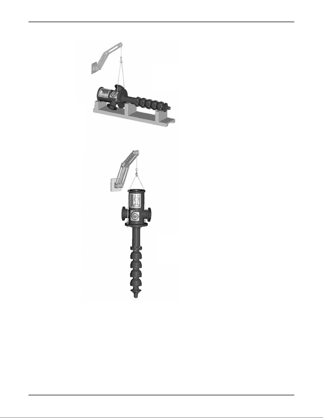
Examples
1
2
Transportation and Storage (Continued)
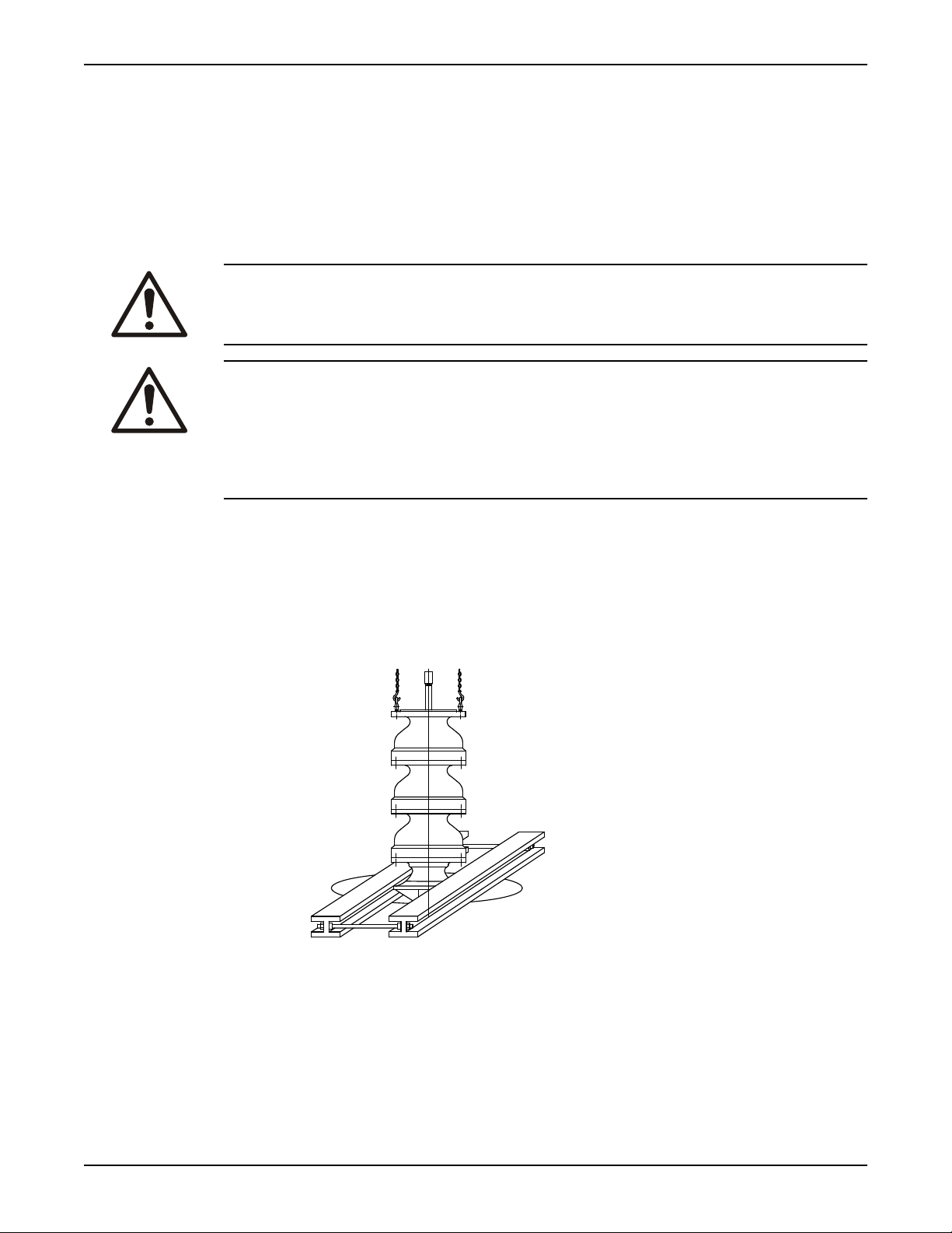
1. Horizontal position
2. Vertical position
Figure 1: VIC lifted from horizontal to vertical (for pumps up to 15 feet [4.6 meters] in length)
Model VIC Installation, Operation, and Maintenance 9
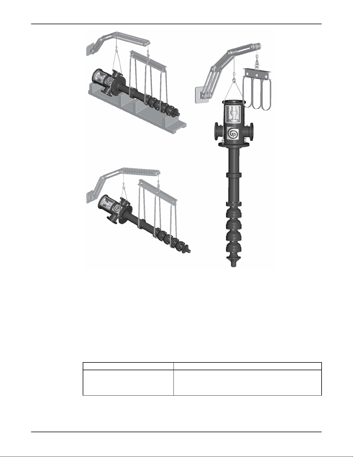
1
2
3
Transportation and Storage (Continued)
1. Horizontal position
2. Intermediate position
3. Vertical position
Figure 2: VIC lifted from horizontal to vertical (for pumps up to 30 feet [9.1 meters] in length)
Pump storage requirements
Requirements
Vertical pumps require proper preparation for storage and regular maintenance during storage. The pump
is considered in storage when it has been delivered to the job site and is awaiting installation.
For specific requirements for storing motors, gearheads, and engines, contact the equipment manufacturer.
Storage preparation
Condition Proper preparation
Indoor storage area (preferred)
10 Model VIC Installation, Operation, and Maintenance
• Pave the area.
• Clean the area.
• Drain the area and keep it free from flooding.

Condition Proper preparation
Outdoor storage area (when indoor
storage is not available)
Placement of pumps and component
parts
Stacking of pumps or component parts
Rotation of the pump and bowl
assembly shaft
Controlled storage facilities
Uncontrolled storage facilities that have
uneven temperatures, higher humidity,
and/or dusty conditions)
• Observe all indoor storage requirements.
• Use weather-proof coverings such as flame-resistant sheeting
or tarpaulins.
• Place coverings in a manner that maximizes drainage and air
circulation.
• Tie coverings down in order to protect the pump from wind
damage.
• Place the pump on skids, pallets, or shoring higher than 6 in.
(15 cm) from the ground for good air circulation.
• Sort the parts in order to permit easy access for inspection
and/or maintenance without excessive handling.
• Make sure that racks, containers, or crates bear the full
weight of pumps or parts in order to prevent distortion.
• Keep identification markings readily visible.
• Immediately replace any cover you remove for internal
access.
• Rotate the pump and bowl assembly shaft counterclockwise
once a month, at a minimum.
• Never leave the shaft in a previous position or in the extreme
raised or lowered lateral position.
• Make sure that the shaft rotates freely.
• Maintain an even temperature of 10°F (6°C) or higher above
the dew point.
• Keep the relative humidity to less than 50%.
• Make sure that there is little or no dust.
• Inspect the pump periodically to make sure that all
preservatives are intact.
• Seal all pipe threads and flanged pipe covers with tape.
Transportation and Storage (Continued)
When pump is not in regular operation
If a pump has been installed, but is not in regular operation for an extended period of time, such as during
a seasonal shutdown, then operate it for at least 15 minutes every two weeks, if possible.
Prepare the pump for long-term storage
For storage periods over six months, you must follow the pump storage requirements and this procedure:
1. Inspect the lube-oil and seal-flush piping and either fill the piping with rust-preventative oil, or recoat
the piping periodically in order to prevent corrosion.
2. Place 10 lbs (4.5 kg) of moisture-absorbing desiccant or 5.0 lbs (2.3 kg) of vapor-phase inhibitor
crystals near the center of the pump.
3. If the pump is assembled, place an additional one pound (0.5 kg) in the discharge nozzle and securely
fasten the nozzle to the discharge elbow.
4. Install a moisture indicator near the perimeter of the pump.
5. Cover the pump with black polyethylene with a minimum thickness of 6.0 mil (0.15 mm), and seal it
with tape.
6. Provide a small ventilation hole approximately 0.5 in. (12.0 mm) in diameter.
7. Provide a roof or shed shelter in order to protect the pump from direct exposure to the elements.
Model VIC Installation, Operation, and Maintenance 11

Product Description
Product Description
General description
The Model VIC pump is a vertical, industrial, turbine-type pump designed to meet a wide range of
applications.
This pump has these capabilities:
• Capacities up to 70,000 gpm (15,900 m3/h)
• Heads up to 4,500 ft. (1,372 m)
• Power up to 5,000 hp (3,730 kW)
Bowl assembly
The bowl construction is flanged for accurate alignment and ease of assembly and disassembly. Impellers
are either open or enclosed, depending on the design requirements. For temperatures over 180°F (82°C)
and in the larger size bowls, impellers are keyed to the shaft. Low NPSH first-stage impellers are available
for special applications.
Column
Flanged column construction provides positive shaft and bearing alignment, and also eases assembly and
disassembly. The lineshaft is supported within the column with the use of bearing retainers that are spaced
in order to provide vibration-free operation and ensure long bearing and shaft wear.
Discharge head
The discharge head is designed to support the pump and to align the driver to the pump. Driver support
windows provide access to seal piping and allow for easy adjustment of seals and couplings.
Thrust pot
A thrust pot is an option that is used when the driver is not designed to carry the axial pump thrust.
Drivers
Solid shaft drivers are used with most industrial applications. The rigidity of the rotor enhances vibrationfree operation when mechanical seals are used.
You can use hollow shaft drivers in applications that specify packing.
Barrel
The barrel is flanged to support the weight of the pump and driver when it is full of liquid. You can install
the barrel in a sleeve or open steel structure. The suction flange is located on the side of the barrel in the
VIC-L model.
Nameplate information
Important information for ordering
Every pump has a nameplate that provides information about the pump. The nameplate is located on the
discharge head.
When you order spare parts, identify this pump information:
• Model
• Size
• Serial number
• Item numbers of the required parts
Item numbers can be found in the spare parts list.
Nameplate types
Nameplate Description
Pump Provides information about the hydraulic characteristics of the pump.
12 Model VIC Installation, Operation, and Maintenance
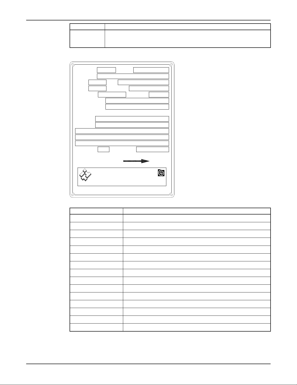
Nameplate Description
SERIAL NO.
P.O. NO.
R.P.M.
MODEL
M.A.W.P. DISCH.
RATED FLOW
M.A.W.P. SUCT.
CASE HYDROSTATIC TEST PRESSURE
DISCHARGE
SUCTION
YEAR BUILT
ITEM NO.
ROTOR LIFT
SIZE
RATED HEAD
INSPECTED BY
(800) 422-5873 (562) 949-2113
ROTATION
NP105_06
ITT
GOULDS PUMPS
Engineered for life
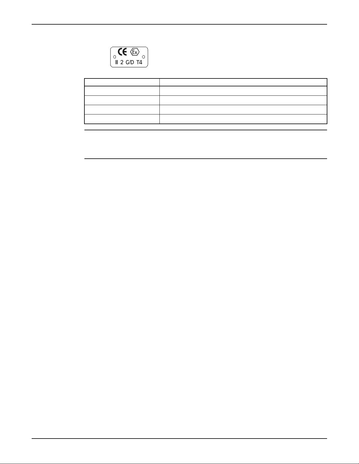
ATEX If applicable, your pump unit might have an ATEX nameplate affixed to the pump, the
Discharge head nameplate
Product Description (Continued)
baseplate, or the discharge head. The nameplate provides information about the ATEX
specifications of this pump.
Table 2: Explanation of discharge head nameplate
Nameplate field Explanation
SERIAL NO. Serial number of the pump
ITEM NO. Pump item number of the customer
P.O. NO. Purchase order number of the customer
MODEL Pump model
SIZE Size of the pump
R.P.M. Rated pump speed, revolutions per minute
ROTOR LIFT Axial lift of the pump shaft and impellers
RATED FLOW Rated pump flow, gpm (m3/hr)
RATED HEAD Rated pump head, ft (m)
M.A.W.P. DISCH. Maximum allowable working discharge pressure, psi (kg/cm2)
M.A.W.P. SUCT. Maximum allowable working suction pressure, psi (kg/cm2)
DISCHARGE Discharge region hydrostatic test pressure, psi (kg/cm2)
SUCTION Suction region hydrostatic test pressure, psi (kg/cm2)
YEAR BUILT Year the pump was built
INSPECTED BY Quality control identification stamp
Model VIC Installation, Operation, and Maintenance 13
Product Description (Continued)
ATEX nameplate
Nameplate field Explanation
II Group 2
2 Category 2
G/D Pump can be used when gas and dust are present
T4 Temperature class
NOTICE: Make sure that the code classifications on the pump are compatible with the specific
environment in which you plan to install the equipment. If they are not compatible, do not operate the
equipment and contact your ITT representative before you proceed.
14 Model VIC Installation, Operation, and Maintenance
Installation
1
2
3
4
5
6
Preinstallation
Inspect the barrel flange or sub-base
1. If an optional sub-base is furnished, remove it from the barrel when it is shipped assembled.
2. Completely clean the underside of the barrel flange or sub-base.
You might need to coat the underside of the barrel flange or sub-base with an epoxy primer which
you can purchase as an option.
3. Remove the rust-preventative solution from the machined topside of the barrel flange with an
appropriate solution.
Concrete foundation requirements
Requirements
Make sure that you meet these requirements when you prepare the pump foundation:
• The foundation must be able to absorb any vibration.
• The foundation must be able to form a permanent and rigid support for the pumping unit.
• The foundation must be of adequate strength in order to support the complete weight of the pump
and driver, plus the weight of the liquid that passes through it.
Installation
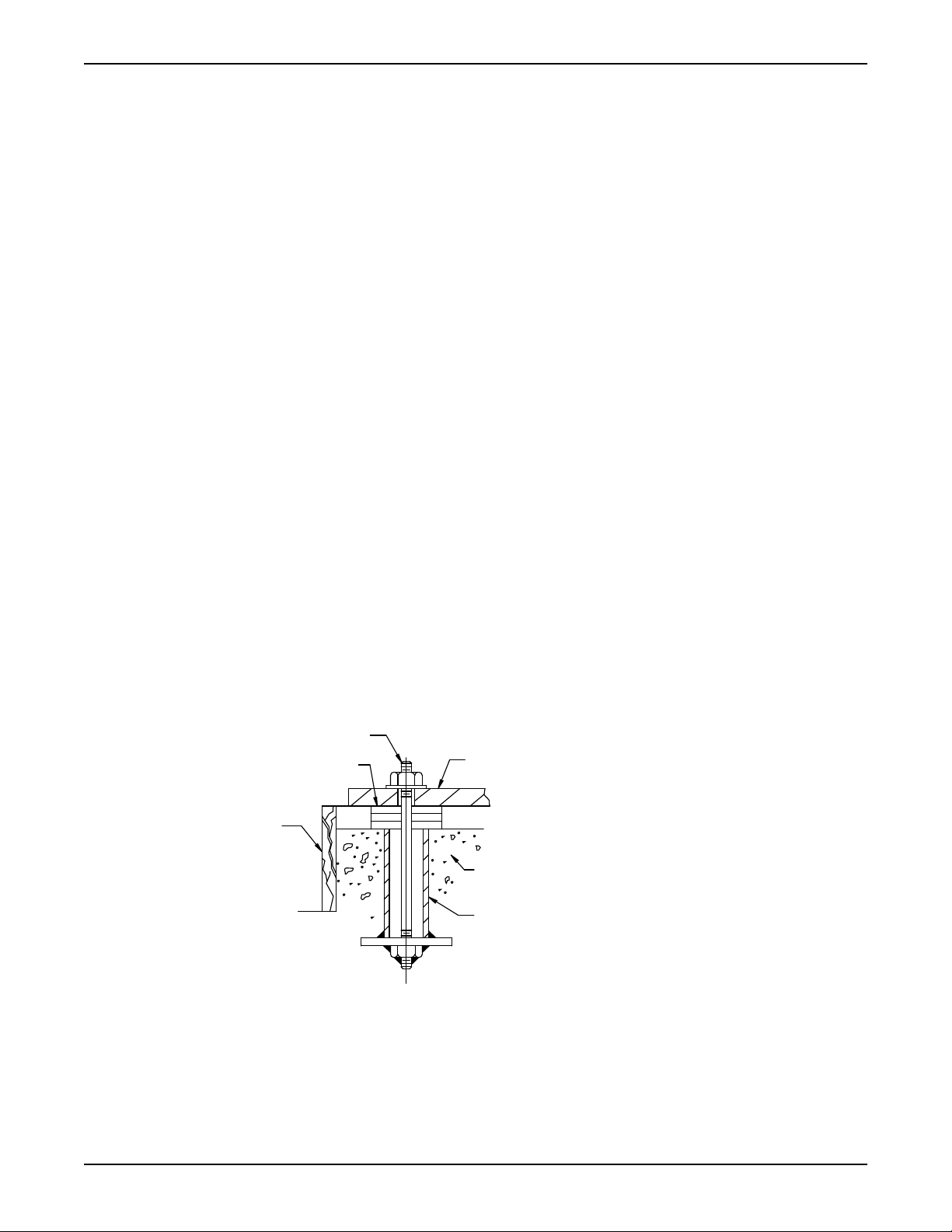
Typical installation
A typical installation has these characteristics:
• Bolts with a pipe sleeve that is two and a half times the size of the bolt diameter embedded in the
concrete
• Properly sized
• Located in accordance with the dimensions given in the example drawing
• Enough space inside the pipe sleeves to allow the final position of the foundation bolts to align with
the holes in the sub-base flange
Model VIC Installation, Operation, and Maintenance 15
1. Barrel flange or sub-base
2. Foundation
3. Sleeve
4. Dam
5. Shims
6. Anchor bolt
Figure 3: Example of a typical installation
1
2
3
4
5
6
7
Installation (Continued)
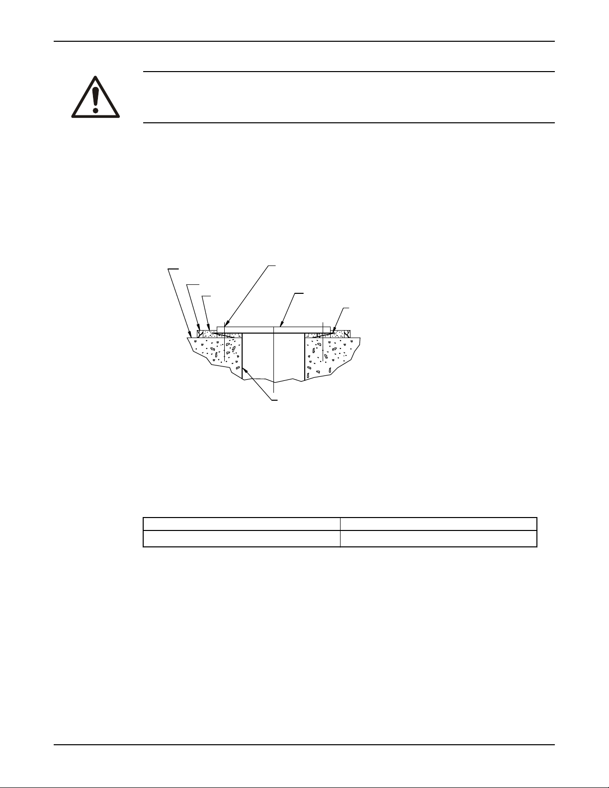
Install the barrel or sub-base on a concrete foundation
CAUTION:
You must earth (ground) all electrical equipment. This applies to the pump equipment, the driver, and any
monitoring equipment. Test the earth (ground) lead to verify that it is connected correctly.
1. Remove water and debris from the anchor bolt holes and sleeves before you start the grout.
2. For sleeve-type bolts, fill the sleeves with packing or rags in order to prevent grout from entering the
sleeves.
3. Carefully lower the barrel or sub-base onto the foundation bolts and hand-tighten the bolt nuts.
4. Use a machinist's level in order to level the barrel or sub-base or a machine surface of the discharge
head using leveling wedges.
In order to ensure an accurate reading, check that the surface being leveled is free from all
contaminants, such as dust.
1. Barrel flange or sub-base
2. Levelling wedges
3. Floor sleeve (optional)
4. Foundation
5. Dam
6. Grout
7. Centerline anchor bolt
5. Level the barrel or sub-base in two directions at 90° on the machined surface.
Table 3: Levelness tolerances
Commercial API
0.005 inches per foot (0.127 mm per meter) 0.001 inches per foot (0.025 mm per meter)
Grout the barrel or sub-base
Non-shrink grout is recommended for this procedure.
1. Inspect the foundation for dust, dirt, oil, chips, and water.
2. Remove any contaminants.
Do not use oil-based cleaners since they do not bond well with grout. Refer to the instructions from
the grout manufacturer.
3. Build a dam around the foundation.
4. Thoroughly wet the foundation.
5. Pour grout to a minimum thickness of 0.375 in. (9.520 mm) between the barrel or sub-base and
concrete foundation, up to the level of the dam.
6. Remove any air bubbles from the grout as it is poured by either puddling, using a vibrator, or
pumping the grout into place.
7. Allow the grout to set at least 48 hours.
16 Model VIC Installation, Operation, and Maintenance
8. Tighten the foundation bolts.
Install the pump on a structural-steel foundation
1. Locate the barrel and pump directly over - or as near as possible to - the main building members,
beams, or walls.
2. Bolt the barrel or sub-base to the support in order to avoid distortion, prevent vibration, and retain
proper alignment.
3. Level the barrel or sub-base using shims.
Piping checklists
General piping checklist
Precautions
CAUTION:
• Never draw piping into place by using force at the flanged connections of the pump. This can impose
dangerous strains on the unit and cause misalignment between the pump and driver. Pipe strain
adversely affects the operation of the pump, which results in physical injury and damage to the
equipment.
• Vary the capacity with the regulating valve in the discharge line. Never throttle the flow from the
suction side. This action can result in decreased performance, unexpected heat generation, and
equipment damage.
Installation (Continued)
Piping guidelines
Checklist
NOTICE:
Flange loads from the piping system, including those from the thermal expansion of the piping, must not
exceed the limits of the pump. Discharge head deformation can result in contact with rotating parts, which
can result in excess heat generation, sparks, and premature failure.
Guidelines for piping are given in the Hydraulic Institute Standards available from the Hydraulic Institute
at 9 Sylvan Way, Parsippany, NJ 07054-3802. You must review this document before you install the pump.
Check Explanation/comment Checked
Check that all piping is supported
independently of, and lined up
naturally with, the pump flange.
Check that only necessary fittings
are used.
Do not connect the piping to the
pump until:
• The grout for the barrel or subbase has hardened.
• The hold-down bolts for the
pump are tightened.
Make sure that all the piping
joints and fittings are airtight.
If the pump handles corrosive
fluids, make sure that the piping
allows you to flush out the liquid
before you remove the pump.
This helps to prevent:
• Strain on the pump
• Misalignment between the pump and the drive unit
• Wear on the pump bearings, seal, and shafting
This helps to minimize friction losses.
—
This prevents air from entering the piping system or
leaks that occur during operation.
—
Model VIC Installation, Operation, and Maintenance 17
Installation (Continued)
Check Explanation/comment Checked
If the pump handles liquids at
elevated temperatures, make sure
that the expansion loops and
joints are properly installed.
Make sure that all piping
components, valves and fittings,
and pump branches are clean
prior to assembly.
Suction and discharge piping checklist
Check Explanation/comment Checked
Check that isolation valves are installed in the
suction and discharge line.
Check that check valves are installed in the
suction and discharge lines, between the
isolation valve and the pump discharge head.
If increasers are used, check that they are
installed between the pump and the check
valve.
If quick-closing valves are installed in the
system, check that cushioning devices are used.
If increasers are used, they must be of the
eccentric type.
This helps to prevent misalignment due to thermal
expansion of the piping.
—
Isolation valves are required for:
• Priming
• Regulation of flow
• Inspection and maintenance of the
pump
The location between the isolation valve
and the pump allows inspection of the
check valve.
The check valve prevents damage to the
pump and seal due to the back flow
through the pump, when the drive unit is
shut off. It is also used to restrain the
liquid flow.
—
This protects the pump from surges and
water hammer.
This prevents air from collecting at the top
of the discharge pipe.
Install a partially-assembled pump
Pumps 20 feet (6 meters) or less in length are usually shipped partially assembled, with the exception of
these parts:
• Driver
• Packing
• Mechanical seal with piping
• Coupling assembly, spacer or non-spacer type
Refer to the Certified Pump Outline Drawing for the location of the anchor-bolt holes.
1. Clean the barrel flange and the bottom of the discharge head.
2. Check that all pump fasteners are tight since transportation and handling can result in bolt relaxation.
3. Install the barrel-to-discharge head O-ring.
4. Attach shackles to the discharge head lifting lugs or thread two eyebolts through the bolt holes in the
mounting flange.
5. Hoist the unit into position over the foundation.
Make sure that the shackles, eyebolts, and sling are rated to handle in excess of the pump weight. See
the outline drawing.
6. Carefully guide the unit so that it does not strike the sides of the sub-base or foundation.
7. Lower the unit until the discharge-head flange engages and rests firmly on the barrel flange, then
secure it with the capscrews provided.
8. When a lineshaft is shipped separately, complete these steps:
18 Model VIC Installation, Operation, and Maintenance
a) Check that the average total runout does not exceed 0.005 in. TIR (0.127 mm) for every 10 ft.
(3 m).
The shaft must be within tolerance prior to installation.
b) Remove the stuffing box, if it is installed.
c) Carefully slide the shaft through the top column bearing retainer.
d) Thread the shaft into the coupling after you replace the stuffing box or seal housing.
Install the bowl assembly
WARNING:
Do not work under a heavy and suspended object unless there is a positive support and safeguards that
will protect you if a hoist or sling fails.
CAUTION:
• Do not attempt to lift the bowl assembly by the pump shaft. This can result in damage to the pump
shaft.
• Do not drop any foreign object into the bowl assembly. This can cause serious damage to the pump
and any downstream components. Any foreign object dropped into the bowl assembly must be
retrieved before you continue with assembly.
Installation (Continued)
1. Check that all capscrews are tight and turn the pump shaft by hand to make sure it turns freely.
2. Remove all accumulated dust, oil, or other foreign material from the external surfaces.
3. Place two I-beam supports across the barrel opening that are strong enough to safely support the
weight of the entire pump assembly.
Connect these I-beams with threaded rods and nuts so you can clamp them firmly together for the
portion to be supported.
4. Place a suitable hoist or derrick over the barrel opening with the hook in the center.
5. Install two threaded eyebolts through the discharge bowl bolt holes 180º apart.
6. Attach a sling to the eyebolts and hoist it into position over the foundation opening.
7. Carefully lower the bowl assembly, guiding the unit so it does not strike the sides of the opening, until
the discharge bowl flange rests firmly on the I-beam supports.
8. Place a cover over the discharge bowl opening to prevent the entrance of dirt or other foreign matter
until you are ready to install the column assembly.
Model VIC Installation, Operation, and Maintenance 19
Installation (Continued)
Install the threaded coupling
If you have a keyed coupling, see the Install the column section of this manual.
CAUTION:
Use Molykote Dow-Corning or an equivalent for all galling material such as 316 stainless steel.
Shaft threads are left hand.
1. Coat the threads with a light coat of oil for a non-galling material, or Molykote for galling material.
2. Install the threaded coupling onto the pump shaft by threading it on for one-half of its length.
You can insert a fine wire in the drill hole at the center of the coupling that serves as a gauge in order
to determine when the coupling is correctly positioned on the pump shaft.
3. Remove the wire.
Install the column
CAUTION:
Use Molykote Dow-Corning or an equivalent for all galling material such as 316 stainless steel.
The bearing retainer is integral with the column. The top flange of the column has a male register and the
bottom flange of the column has a female register.
1. Check the headshaft and lineshaft for straightness.
The average TIR should be less than 0.0005 in. (0.013 mm) per ft. (0.305 m) and not exceed 0.005 in.
(0.127 mm) for every 10 ft. (3 m).
2. Apply a thin film of oil to the lineshaft.
3. Install the coupling:
Shaft threads are left hand.
If your
lineshaft
coupling
is...
Threaded
Keyed
Then...
1. Apply a thin film of oil to the coupling threads if it is a non-galling material. Use a
suitable anti-seize if the coupling is a galling material.
2. Manually start the thread until you feel resistance.
Use a fine wire inserted in the drill hole at the center of the coupling as a gauge to
determine when the coupling is correctly positioned on the shaft.
3. Remove the wire after you install the coupling.
4. Complete the joint using a pair of pipe wrenches, one on top of the pump shaft and
the other on the coupling.
5. Run the upper lineshaft into the coupling and hand-tighten.
Do not apply wrenches on the bearing journal surfaces.
For an illustration of the threaded coupling, see the VIC-T drawing in the Parts List
chapter.
1. Insert the key into the pump shaft.
2. Lower the sleeve over the pump shaft, to approximately 1.0 in. (25.4 mm) below the
top of the shaft.
3. Lower the lineshaft until it touches the pump shaft.
4. Insert the split ring into the grooves of the pump shaft and lineshaft.
20 Model VIC Installation, Operation, and Maintenance
 Loading...