

Goulds Pumps 3656SP Series, H 3656SP, M 3656SP Installation, Operation And Maintenance Instructions
Installation,
Operation and
Maintenance
Instructions
Series 3656SP
MODELS
“M” 3656SP
“H” 3656SP
3656SP
Owner’s Information
Please fill in data from your pump nameplate.
Warranty information is on page 8.
Model Number:
Serial Number:
Dealer:
Dealer Telephone:
Purchase Date:
Installation Date:
Table of Contents
SUBJECT PAGE
Safety Instructions.......................................................... 1
Description and Specifications ........................................ 2
Engineering Data ........................................................... 2
Piping
Suction ...................................................................... 2
Discharge ................................................................... 3
Wiring and Grounding ................................................... 3
Operation ...................................................................... 3
Rotation ........................................................................ 3
Maintenance .................................................................. 3
Disassembly ................................................................... 4
Reassembly .................................................................... 4
Repair Parts ................................................................... 5
Trouble Shooting ........................................................... 6
Goulds Pumps Limited Warranty.................................... 6
IM016R01
1
SAFETY INSTRUCTIONS
TO AVOID SERIOUS OR FATAL PERSONAL INJURY
OR MAJOR PROPERTY DAMAGE, READ AND
FOLLOW ALL SAFETY INSTRUCTIONS IN MANUAL
AND ON PUMP.
This is a SAFETY ALERT SYMBOL.When
you see this symbol on the pump or in the
manual, look for one of the following signal
words and be alert to the potential for
personal injury or property damage.
DANGER
Warns of hazards that WILL cause serious
personal injury, death or major property
damage.
Engineering Data
Series 3656SP Data
Model
“M”3656SP 51⁄8"3
“H” 3656SP 515⁄16" 3 2" NPT 2" NPT
3656SP 515⁄16"5
• Maximum Liquid Temperature: 160° F (71° C)
• Starts per hour: 20 – evenly distributed.
Impeller
Size
HP Suction Discharge ø/Hz
Table 1
1/60
3/60
1/60
3/60
1/60
3/60
WARNING
Warns of hazards that CAN cause serious
personal injury, death or major property
damage.
CAUTION
Warns of hazards that CAN cause personal
injury or property damage.
THIS MANUAL IS INTENDED TO ASSIST IN THE
INSTALLATION AND OPERATION OF THIS UNIT
AND MUST BE KEPT WITH THE PUMP.
MAINTAIN ALL SAFETY DECALS.
NOTICE: INSPECT UNIT FOR DAMAGE AND
REPORT ALL DAMAGE TO THE CARRIER
OR DEALER IMMEDIATELY. DO NOT USE
PUMP IF DAMAGE IS SUSPECTED.
WARNING
UNIT NOT DESIGNED FOR USE
WITH HAZARDOUS LIQUIDS OR
FLAMMABLE GASES.
Hazardous fluids
can cause fire,
burns or death.
NOTICE: INSPECT UNIT FOR DAMAGE AND REPORT
ALL DAMAGE TO THE CARRIER OR
DEALER IMMEDIATELY.
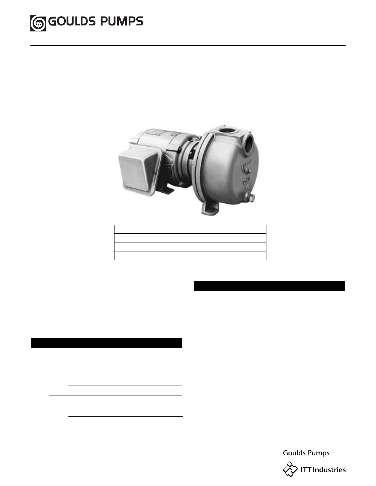
Description and Specifications
• The 3656SP Series embraces a line of end suction single
stage, self-priming centrifugal pumps for lawn sprinkling,
HVAC systems, and general water transfer.
• Casing is cast iron construction with tapped openings
provided for vacuum gauge and casing drain.
• Impeller is bronze, enclosed design, balanced for smooth
operation and keyed to motor shaft.
• ALL motors are NEMA standard, 3500 RPM, open drip
proof or TEFC enclosure.
Piping
• Pump MUST be installed horizontally on a solid flat surface,
with discharge on top.
• Allow adequate space for servicing and ventilation. Protect
the unit from weather and water damage due to rain or
flooding or freezing temperatures.
• Piping should be no smaller than the suction and discharge
connections and kept short as possible, avoiding unnecessary
fittings to minimize friction losses. See Table 1
• All piping MUST be independently supported and MUST
NOT place any piping loads on the pump.
NOTICE: DO NOT FORCE PIPING INTO PLACE AT
PUMP SUCTION AND DISCHARGE
CONNECTIONS.
• The use of Teflon™ tape, or equivalent, is recommended for
ALL pipe joints.
• All pipe joints MUST be airtight.
PIPING – SUCTION
• Total suction lift, including elevation and pipe friction loss,
should not exceed:
3656SP “M” 20 feet of Head (6.1 m)
3656SP “H”20 feet of Head (6.1 m)
3656SP 25 feet of Head (7.6 m)
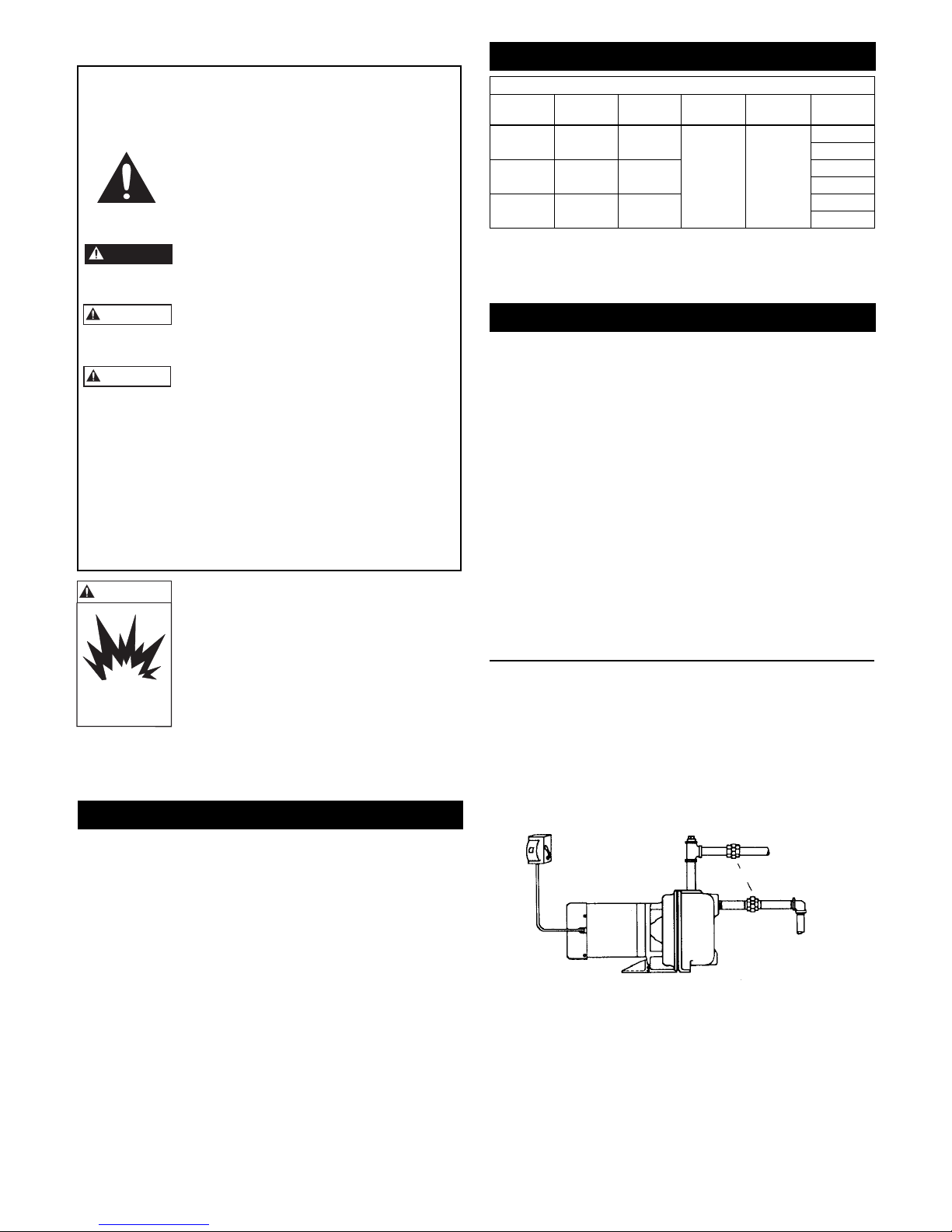
• Install an airtight union in the suction line close to the pump.
See Figure 1.
PRIMING
FUSED OR
CIRCUIT BREAKER
DISCONNECT MEANS
OPENING
DISCHARGE
UNION
SUCTION
Figure 1
2
• Installation of a foot valve at the liquid source, or a check
Hazardous pressure
can cause personal
injury or property
damage.
CAUTION
valve after the pump discharge, is recommended.
NOTICE: FOR INSTALLATIONS WITH LONG SUCTION
PIPING, BOTH A FOOT VALVE AND A
CHECK VALVE ARE RECOMMENDED.
• To avoid air pockets, no part of the piping should be above
the pump suction connection and piping should slope
upward from liquid source.
• For installations with long suction piping, fill the suction pipe
with water before connecting to pump.
PIPING – DISCHARGE
• Install a tee at the discharge connection of the pump. The top
opening of the tee is required for initial priming. See Figure 1.
Wiring and Grounding
WARNING
Hazardous voltage
can shock, burn or
cause death.
Electrical supply MUST match pump’s nameplate
specifications. Incorrect voltage can cause fire,
damage to the motor, and voids warranty.
Motors without built-in protection MUST be
provided with contactors and thermal overloads for
single phase motors, or starters with heaters for
three phase motors. See motor nameplate.
• Follow motor manufacturer’s wiring diagram on the
motor nameplate or terminal cover carefully.
• Use only copper wire to motor and ground. The ground
wire MUST be at least as large as the wire to the motor.
Wires should be color coded for ease of maintenance.
WARNING
Hazardous
voltage
FAILURE TO PERMANENTLY
GROUND THE PUMP, MOTOR AND
CONTROLS BEFORE CONNECTING
TO ELECTRICAL POWER CAN
CAUSE SHOCK, BURNS, OR DEATH.
Install, ground and wire according
to local and National Electrical
Code requirements.
Install an all leg electrical power
disconnect switch near the pump.
Disconnect electrical power, before
installing or servicing pump.
Operation
WARNING
Hazardous voltage
can shock, burn or
cause death.
SPLASHING OR IMMERSING OPEN
DRIP PROOF MOTORS IN WATER
CAN CAUSE FIRE, SHOCK, BURNS
OR DEATH.
• Fill pump through opening in top of tee with clean water.
See Figure 1.
• Install pipe plug in top using Teflon™ tape or equivalent on
male threads.
NOTICE: IF PUMP IS DRAINEDOR SHUT OFF DURING
PRIMING PERIOD, ENSURE CASING IS
REFILLED BEFORE RESTARTING PUMP.
• Start the pump motor and wait for system pressure to stabilize.
If system pressure is surging, or prolonged pressure drop is
experienced, the systemmay not be completely primed.
Rotation
NOTICE: INCORRECT ROTATION MAY CAUSE
DAMAGE TO THE PUMP AND VOIDS THE
WARRANTY.
• Correct rotation is right hand, CLOCKWISE when viewed
from the motor end.
• Three phase unit rotation may be checked by removing
motor end cap or plug and observing rotation of motor shaft.
To reverse rotation, reverse any two of the three motor leads.
Maintenance
WARNING
Hazardous
Machinery
• No lubrication is required on pump. For motor lubrication,
refer to and follow manufacturer’s instructions.
Seasonal Service
• To REMOVE pump from service, remove all drain plugs
and drain all piping.
• To RETURN pump to service, replace all drain plugs using
Teflon™ tape or equivalent.
• Reconnect suction line if removed, examine union and repair
if necessary.
• Reprime and operate pump following all instructions and
warnings in the “OPERATION” section of manual.
FAILURE TO DISCONNECT AND
LOCKOUT ELECTRICAL POWER
BEFORE ATTEMPTING ANY MAINTENANCE CAN CAUSE SEVERE
PERSONAL INJURY.
FAILURE TO RELIEVE SYSTEM
PRESSURE AND DRAIN SYSTEM
BEFORE ATTEMPTING ANY MAINTENANCE CAN CAUSE PERSONAL
INJURY OR PROPERTY DAMAGE.
WARNING
OPERATION WITHOUT PRIME, OR
AGAINST A CLOSED DISCHARGE
VALVE, CAN GENERATE HOT
WATER OR STEAM CAUSING
INJURY OR PROPERTY DAMAGE.
Extreme heat can
cause personal injury
or property damage.
3

Disassembly
• Follow ALL warnings and instructions in the
“MAINTENANCE” section of this manual.
1. Remove motor hold down bolts.
2. Remove casing bolts (371A).
3. Remove back pull-out assembly from casing (100).
4. Remove guidevane seal ring (349) and discard.
5. Remove casing/adapter gasket (351) and discard.
6. Remove guidevane screws (459) and guidevane (347) from
adapter.
7. Insert a screwdriver into one of the impeller waterways to
restrain motor shaft from rotation and remove impeller
bolt (198). Discard.
8. Remove impeller washer (199), impeller (101), and
impeller key (178). If impeller is difficult to remove, insert
two pry bars between impeller and adapter, 180° apart,
and CAREFULLY pry off impeller.
9. Remove motor adapter bolts (371) and adapter (108) from
motor, pulling with it the mechanical seal (383).
10. Push stationary seat of mechanical seal out of the motor
adapter and discard.
11. Inspect shaft sleeve (126), if damaged or badly scored,
remove by heating with a torch. Discard.
NOTICE: EXERCISE CARE IN HANDLING HOT SHAFT
SLEEVE.
Reassembly
• All parts should be cleaned before reassembly.
• Refer to parts list for description of replacement items.
Specify pump index number when ordering parts.
1. Inspect shaft, removing any debris or burrs.
2. When replacing shaft sleeve, apply new shaft sleeve’s bore
with LOCQUIC® Primer N, or equivalent. Let parts dry
and then apply LOCTITE® #262 on the same surfaces.
Slide new sleeve over shaft with a twisting motion, wipe off
excess. Let cure according to instructions.
NOTICE: MECHANICAL SEAL MUST BE REPLACED
WHENEVER SEAL HAS BEEN REMOVED.
FOLLOW SEAL MANUFACTURER’S
INSTRUCTIONS CAREFULLY.
3. If necessary, seat ring may be lubricated with water or
glycerin to aid in installation. DO NOT contaminate the
seal face. Fully and squarely install the stationary seat into
the adapter. With a clean cloth, CAREFULLY wipe the
seat face clean of debris. DO NOT damage the seal
seat face.
4. Reinstall the motor adapter on the motor, making sure that
the motor shaft does not dislocate or damage the stationary
seal seat.
5. Fully and squarely install the seal rotary assembly against
the stationary seat. Be sure rotating seal face does not drop
out of the holding collar and DO NOT damage seal face.
6. Install impeller key in shaft keyway. Mount impeller on
shaft and push until it bottoms.
7. Install new im peller washer.
8. Insert a screwdriver in a waterway passage of the impeller
holding it against rotation and install the new impeller bolt.
9. Remove any burrs caused by screwdriver on the periphery
of impeller in waterway passages.
10. Replace guidevane, being sure that impeller hub is not
binding, tightening screws alternately and evenly. Check
impeller for binding by rotating the motor shaft by use of a
screwdriver slot or flats on the end of the motor shaft
(removal of the motor end plug or cover will be necessary).
If binding occurs, loosen screws, readjust guidevane until
impeller hub turns freely. Tighten screws.
11. Install new guidevane seal ring.
12. Install new casing/adapter gasket.
NOTICE: ENSURE CASING/ADAPTER GASKET
SURFACES ARE FREE OF DEBRIS OR
LEAKING WILL RESULT.
13. Install motor and rotaing assembly into casing, tighten
casing bolts alternately and evenly.
14. Replace foot bolts and motor end plug or cover.
15. Check for free rotation after assembly is complete.
16. Replace all drain plugs, using Teflon™ tape on male
threads.
17. Prime according to instructions in the “OPERATION”
section of the manual.
4

Series 3656SP Repair Parts
Item
Number
100 Casing Cast iron
101 Impeller Bronze
108 Motor adapter Cast iron
126 Shaft sleeve Stainless steel
178 Impeller key Stainless steel
198 Impeller bolt (self-locking) Stainless steel
199 Impeller washer Stainless steel
347 Guidevane Bronze
349 Guidevane seal ring BUNA-N
351 Casing/adapter gasket Composite
371 Hex head cap screw (adapter/motor) Steel
371A Hex head cap screw (adapter/casing) Steel
383 Mechanical seal John Crane Type 21: 11⁄4"
408 Pipe plug 1⁄4" x 3⁄4" Plated steel
459 Fillister head screw Stainless steel
Description Material
Trouble Shooting
WARNING
Hazardous voltage
can shock, burn or
cause death.
SYMPTOM
Motor Not Running:
See Probable Causes 1 through 5.
Little or No Water Delivered:
See Probable Causes 3, 4, 6 through 12, 15.
Excessive Noise and Vibration:
See Probable Causes 3, 6, 7, 10, 12, 13, 14.
PROBABLE CAUSES
1. Motor thermal protector tripped.
2. Open circuit breaker or blown fuse.
3. Impeller binding.
4. Motor improperly wired.
5. Defective motor.
6. Pump is not primed, air or gases in pumpage.
7. Discharge, suction plugged or valve closed.
8. Incorrect rotation. (3 phase only)
9. Low voltage or phase loss.
10. Impeller worn or plugged.
11. System head too high.
12. NPSHA too low – excessive suction lift or loss.
13. Discharge head too low – excessive flow rates.
14. Pump, motor or piping loose.
15. End of suction piping not submerged.
FAILURE TO DISCONNECT
ELECTRICAL POWER BEFORE
ATTEMPTING ANY MAINTENANCE
CAN CAUSE SHOCK, BURNS OR
DEATH.
5

Notes
6

Notes
7
This warranty applies to all water systems pumps manufactured by Goulds Pumps.
Any part or parts found to be defective within the warranty period shall be replaced at no charge to the dealer during the warranty period. The warranty period shall exist for a
period of twelve (12) months from date of installation or eighteen (18) months from date of manufacture, whichever period is shorter.
A dealer who believes that a warranty claim exists must contact the authorized GouldsPumps distributor from whom the pump was purchased and furnish complete details
regarding the claim. The distributor is authorized to adjust any warranty claims utilizing the Goulds Pumps Customer Service Department.
The warranty excludes:
(a) Labor, transportation and related costs incurred by the dealer;
(b) Reinstallation costs of repaired equipment;
(c) Reinstallation costs of replacement equipment;
(d) Consequential damages of any kind; and,
(e) Reimbursement for loss caused by interruption of service.
For purposes of this warranty, the following terms have these definitions:
(1) “Distributor” means any individual, partnership, corporation, association, or other legal relationship that stands between Goulds Pumps and the dealer in purchases,
consignments or contracts for sale of the subject pumps.
(2) “Dealer” means any individual, partnership, corporation, association, or other legal relationship which engages in the business of selling or leasing pumps to customers.
(3) “Customer” means any entity who buys or leases the subject pumps from a dealer. The “customer” may mean an individual, partnership, corporation, limited liability
company, association or other legal entity which may engage in any type of business.
THIS WARRANTY EXTENDS TO THE DEALER ONLY.
©1999 Goulds Pumps
8
Printed in U.S.A.
GOULDS PUMPS LIMITED WARRANTY
 Loading...