

Page 1
INSTALLATION AND OPERATING INSTRUCTIONS
MODEL ICM/ICMP
Magnetic Drive
Chemical Process Pump
Bearing lubrication: Grease
Bearing pedestal size: 1+2
Keep for future use!
This operating manual must
be strictly observed before
transport, installation, commissioning etc.
Reproduction is generally permitted with indication of the
source.
© ITT
9330-050-en Revision 05 Edition 03/2003
7500.1A 501
Page 2

IMPORTANT SAFETY NOTICE
To: Our Valued Customers
User safety is a major focus in the design of our products. Following the precautions outlined in this
manual will minimize your risk of injury.
ITT Goulds pumps will provide safe, trouble-free service when properly installed, maintained, and
operated.
Safe installation, operation, and maintenance of ITT Goulds Pumps equipment are an essential end user
responsibility. This Pump Safety Manual identifies specific safety risks that must be considered at all
times during product life. Understanding and adhering to these safety warnings is mandatory to ensure
personnel, property, and/or the environment will not be harmed. Adherence to these warnings alone,
however, is not sufficient — it is anticipated that the end user will also comply with industry and corporate
safety standards. Identifying and eliminating unsafe installation, operating and maintenance practices is
the responsibility of all individuals involved in the installation, operation, and maintenance of industrial
equipment.
Please take the time to review and understand the safe installation, operation, and maintenance guidelines
outlined in this Pump Safety Manual and the Instruction, Operation, and Maintenance (IOM) manual.
Current manuals are available at
your nearest Goulds Pumps sales representative.
www.gouldspumps.com/literature_ioms.html or by contacting
These manuals must be read and understood before installation and star t-up.
For additional information, contact your nearest Goulds Pumps sales representative or visit our Web site at
www.gouldspumps.com.
S-1
Page 3

SAFETY WARNINGS
Specific to pumping equipment, significant risks bear reinforcement above and beyond normal safety precautions.
WARNING
A pump is a pressure vessel with rotating parts that can be hazard o us. An y press ure vessel can explode,
rupture, or discharge its contents if sufficiently ove r press u r i zed causi n g deat h, personal injury, property
damage, and/or damage to the environment. All necessary measures must be taken to ensure over
pressurization does not occur.
WARNING
Operation of any pumping system with a blocked suction and discharge must be avoided in all cases.
Operation, even for a brief period under these conditions, can cause superheating of enclosed pumpage and
result in a violent explosion. All necessary measures must be taken by the end user to ensure this condition is
avoided.
WARNING
The pump may handle hazardous and/or toxic fluids. Care must be taken to identify the contents of the pump
and eliminate the possibility of exposure, particularly if hazardous and/or toxic. Potential hazards include, but
are not limited to, high temperature, flammable, acidic, caustic, explosive, and other risks.
WARNING
Pumping equipment Instruction, Operation, and Maintenance manuals clearly identify accepted methods for
disassembling pumping units. These methods must be adhered to. Specifically, applying heat to impellers
and/or impeller retaining devices to aid in their removal is strictly forbidden. Trapped liquid can rapidly
expand and result in a violent explosion and injury.
ITT Goulds Pumps will not accept responsibility for physical injury, damage, or delays caused by a failure to
observe the instructions for installation, operation, and maintenance contained in this Pump Safety Manual or the
current IOM available at www.gouldspumps.com/literature.
S-2
Page 4

SAFETY
DEFINITIONS
Throughout this manual the words WARNING, CAUTION, ELECTRICAL, and ATEX are used to indicate
where special operator attention is required.
Observe all Cautions and Warnings highlighted in this Pump Safety Manual and the IOM provided with
your equipment.
WARNING
Indicates a hazardous situation which, if not avoided, could result in death or serious injury.
Example:
Pump shall never be operated without coupling guard installed correctly.
CAUTION
Indicates a hazardous situation which, if not avoi ded, could result in minor or moderate injury.
Example: Throttling flow from the suction side may cause cavitation and pump damage.
ELECTRICAL HAZARD
Indicates the possibility of electrical risks if directions are not followed.
Example: Lock out driver power to prevent electric shock, accidental start-up, and physical injury.
When installed in potentially explosive atmospheres, the instructions that follow the Ex symbol must be
followed. Personal injury and/or equipment damage may occur if these instructions are not followed. If there
is any question regarding these requirements or if the equipment is to be modified, please contact an ITT
Goulds Pumps representative before proceeding.
Example:
parts, resulting in a spark and heat generation.
Improper impeller adjustment could cause contact between the rotating and stationary
S-3
Page 5

GENERAL PRECAUTIONS
WARNING
A pump is a pressure vessel with rotating parts that can be hazardous. Hazardous fluids may be contained by the
pump including high temperature, flammable, acidic, caustic, explosive, and other risks. Operators and
maintenance personnel must realize this and follow safety measures. Personal injuries will result if procedures
outlined in this manual are not followed. ITT Goulds Pumps will not accept responsibility for physical injury,
damage or delays caused by a failure to observe the instructions in this manual and the IOM provided with your
equipment.
WARNING
WARNING
General Precautions
NEVER use heat to disassemble pump due to risk of explosion from tapped liquid.
NEVER APPLY HEAT TO REMOVE IMPELLER. It may explode due to
trapped liquid.
WARNING
WARNING
WARNING
WARNING
WARNING
WARNING
WARNING
WARNING
WARNING
NEVER operate pump without safety devices installed.
NEVER operate pump without coupling guard correctly installed.
NEVER run pump below recommended minimum flow when dry, or without
prime.
ALWAYS lock out power to the driver befo re per fo rming pump maintenance.
NEVER operate pump with discharge valve closed.
NEVER operate pump with suction valve closed.
DO NOT change service application without approval of an authorized ITT
Goulds Pumps representative.
Safety Apparel:
Insulated work gloves when handling hot bearings or using bearing heater
Heavy work gloves when handling parts with shar p ed ges, especially
impellers
Safety glasses (with side shields) for eye protection
Steel-toed shoes for foot protection when handling parts, heavy tools, etc.
Other personal protective equipment to protect against hazardous/toxic fluids
Receiving:
Assembled pumping units and their components are heavy. Failure to properly lift
and support equipment can result in serious physical injury and/or equipment
damage. Lift equipment only at specifically identified lifting points or as
instructed in the current IOM. Current manuals are available at
www.gouldspumps.com/literature_ioms.html or from your local ITT Goulds
Pumps sales representative. Note: Lifting devices (eyebolts, slings, spreaders, etc.)
must be rated, selected, and used for the entire load being lifted.
Alignment:
WARNING
Shaft alignment procedures must be followed to prevent catastrophic failure of
drive components or unintended contact of rotating parts. Follow coupling
manufacturer’s coupling installation and operation procedures.
S-4
Page 6

WARNING
CAUTION
General Precautions
Before beginning any alignment procedure, make sure driver power is locked out.
Failure to lock out driver power will result in serious physical injury.
Piping:
Never draw piping into place by forcing at the flan ged con necti on s of t he pump.
This may impose dangerous strains on the unit and cause misalignment between
pump and driver. Pipe strain will adversely effect the operation of the pump
resulting in physical injury and damage to the equipment.
WARNING
WARNING
WARNING
WARNING
WARNING
WARNING
WARNING
WARNING
WARNING
WARNING
WARNING
CAUTION
CAUTION
WARNING
Flanged Connections:
Use only fasteners of the proper size and material.
Replace all corroded fasteners.
Ensure all fasteners are properly tightened and there are no missing fasteners.
Startup and Operation:
When installing in a potentially explosive environment, please ensure that the
motor is properly certified.
Operating pump in reverse rotation may result in contact of metal parts, heat
generation, and breach of containment.
Lock out driver power to prevent accidental start-up and physical injury.
The impeller clearance setting procedure must be followed. Improperly setting
the clearance or not following any of the proper procedures can result in sparks,
unexpected heat generation and equipment damage.
If using a cartridge mechanical seal, the centering clips must be installed and set
screws loosened prior to setting impeller clearance. Failure to do so could result
in sparks, heat generation, and mechanical seal damage.
The coupling used in an ATEX classified environment must be properly certified
and must be constructed from a non-sparking material.
Never operate a pump without coupling guard properly installed. Personal injury
will occur if pump is run without coupling guard.
Make sure to properly lubricate the bearings. Failure to do so may result in excess
heat generation, sparks, and / or premature failure.
The mechanical seal used in an ATEX classified environment must be properly
certified. Prior to start up, ensure all points of potential leakage of process fluid to
the work environment are closed.
Never operate the pump without liquid supplied to mechanical seal. Running a
mechanical seal dry, even for a few seconds, can cause seal damage and must be
avoided. Physical injury can occur if mechanical seal fails.
Never attempt to replace packing until the driver is properly locked out and the
coupling spacer is removed.
WARNING
WARNING
S-5
Dynamic seals are not allowed in an ATEX classified environment.
DO NOT operate pump below minimum rated flows or with suction and/or
discharge valve closed. These conditions may create an explosive hazard due to
vaporization of pumpage and can quickly lead to pump failure and physical injury.
Page 7

WARNING
WARNING
WARNING
WARNING
WARNING
CAUTION
CAUTION
WARNING
CAUTION
CAUTION
General Precautions
Ensure pump is isolated from system and pressure is relieved before
disassembling pump, removing plu gs, ope ni n g vent or drain valves, or
disconnecting piping.
Shutdown, Disassembly, and Reassembly:
Pump components can be heavy. Proper methods of lifting must be employed to
avoid physical injury and/or equipment damage. Steel toed shoes must be worn at
all times.
The pump may handle hazardous and/or toxic fluids. Observe proper
decontamination procedures. Proper personal protective equipment should be
worn. Precautions must be taken to prevent physical injury. Pumpage must be
handled and disposed of in conformance with applicable environmental
regulations.
Operator must be aware of pumpage and safety precautions to prevent physical
injury.
Lock out driver power to prevent accidental startup and physical injury.
Allow all system and pump components to cool before handling them to prevent
physical injury.
If pump is a Model NM3171, NM3196, 3198, 3298, V3298, SP3298, 4150, 4550,
or 3107, there may be a risk of static electric discharge from plastic parts that are
not properly grounded. If pumped fluid is non-conductive, pump should be
drained and flushed with a conductive fluid under conditions that will not allow
for a spark to be released to the atmosphere.
Never apply heat to remove an impeller. The use of heat may cause an explosion
due to trapped fluid, resulting in severe physical injury and property damage.
Wear heavy work gloves when handling impellers as sharp edges may cause
physical injury.
Wear insulated gloves when using a bearing heater. Bearings will get hot and can
cause physical injury.
S-6
Page 8
ATEX CONSIDERATIONS and INTENDED USE
Special care must be taken in potentially explosive environments to ensure that the equipment is properly
maintained. This includes but is not limited to:
1. Monitoring the pump frame and liquid end temperature.
2. Maintaining proper bearing lubrication.
3. Ensuring that the pump is operated in the intended hydraulic range.
The ATEX conformance is only applicable when the pump unit is operated within its intended use. Operating,
installing or maintaining the pump unit in any way that is not covered in the Instruction, Operation, and
Maintenance manual (IOM) can cause serious personal injury or damage to the equipment. This includes any
modification to the equipment or use of parts not provided by ITT Goulds Pumps. If there is any question
regarding the intended use of the equipment, please contact an ITT Goulds represe ntative before proceeding.
Current IOMs are available at
Pumps Sales representative.
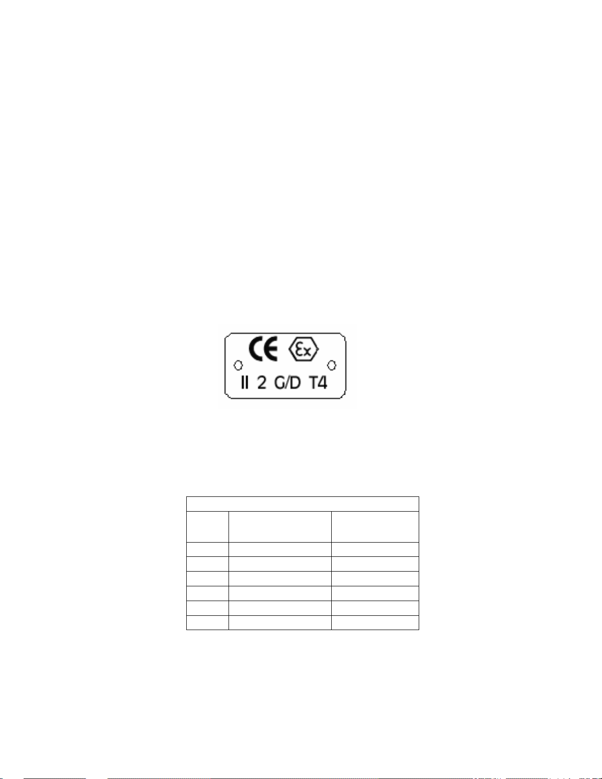
All pumping unit (pump, seal, coupling, motor and pump accessories) certified for use in an ATEX classified
environment, are identified by an ATEX tag secured to the pump or the baseplate on which it is mounted. A
typical tag would look like this:
www.gouldspumps.com/literature_ioms.html or from your local ITT Goulds
The CE and the Ex designate the ATEX compliance. The code directly below these symbols reads as follows:
II = Group 2
2 = Category 2
G/D = Gas and Dust present
T4 = Temperature class, can be T1 to T6 (see Table 1)
Table 1
Max permissible
surface temperature
Code
T1 842 (450) 700 (372)
T2 572 (300) 530 (277)
T3 392 (200) 350 (177)
T4 275 (135) 235 (113)
T5 212 (100) Option not available
T6 185 (85) Option not available
o
F (oC)
The code classification marked on the equipment must be in accordance with the specified area where the
equipment will be installed. If it is not, do not operate the equipment and contact your ITT Goulds Pumps sales
representative before proceeding.
Max permissible
liquid temperature
o
F (oC)
S-7
Page 9

PARTS
The use of genuine Goulds parts will provide the safest and
most reliable operation of your pump. ITT Goulds Pumps ISO
certification and quality control procedures ensure the parts are
manufactured to the highest quality and safety levels.
Please contact your local Goulds representative for details on
genuine Goulds parts.
S-8
Page 10

List of Contents
Installation and Operating Instructions
Model ICM/ICMP, for life grease lubrication
1 Technical Data .................................... 3
1.1 Intended use............................................... 4
1.2 Tightening torques...................................... 5
1.3 Type plate, dry-running, CE and housing
markings..................................................... 5
2 Notes on safety................................... 6
2.1 For the customer/operator.......................... 6
2.2 For maintenance ........................................ 7
2.3 Conversion work and production of spare
parts by the customer................................. 7
2.4 Inadmissible modes of operation ............... 7
2.5 Explosion protection ................................... 7
2.5.1 Filling the unit ........................................................ 7
2.5.2 Special operating conditions ................................. 7
2.5.3 Identification .......................................................... 8
2.5.4 Check of the direction of rotation........................... 8
2.5.5 Mode of operation of the pump ............................. 8
2.5.6 Temperature limits................................................. 8
2.5.7 Maintenance.......................................................... 9
2.5.8 Electric peripheral equipment ................................ 9
3 Transport and storage ....................... 9
3.1 Return consignments ...............................10
4 Product description.......................... 10
5 Installation ........................................ 11
5.1 Safety regulations..................................... 11
5.2 Installation of pump/unit ........................... 11
5.3 Alignment of pump – coupling - motor .....11
5.4 Piping ....................................................... 11
5.4.1 Nominal size........................................................ 11
5.4.2 Nozzle loads........................................................ 12
5.4.3 Suction line.......................................................... 12
5.4.4 Supply lines ......................................................... 12
5.4.5 Discharge line...................................................... 12
5.4.6 Venting and evacuating ....................................... 12
5.5 Piping internals.............................................
5.6 Monitoring facilities................................... 12
5.7 Drive ......................................................... 13
5.8 Coupling ................................................... 13
5.9 Coupling guard ......................................... 13
5.10 Final check ............................................... 13
5.11 Electric connection ................................... 13
6 Commissioning/Shutdown .............. 14
6.1 Initial commissioning.................................14
6.1.1 Filling the pump housing ..................................... 14
6.1.2 Start-up ............................................................... 14
6.2 Operating limits.........................................14
6.2.1 Abrasive media ................................................... 14
6.2.2 Min./max. flow rate .............................................. 14
6.3 Shutdown..................................................15
6.4 Restarting .................................................15
6.5 Inadmissible modes of operations and their
consequences (examples)........................15
7 Maintenance...................................... 16
7.1 Screw connections of the housing............16
7.2 Bearing pedestal.......................................16
7.3 Cleaning....................................................16
7.4 Stand-by pumps........................................16
7.5 Notes on dismantling ................................16
7.5.1 Protective clothes................................................ 16
7.5.2 Magnetic fields .................................................... 16
7.5.3 Changing the radial ball bearings ....................... 17
7.6 Dismantling ...............................................17
7.6.1 Removing bearing pedestal ................................ 17
7.6.2 Dismantling bearing pedestal.............................. 17
7.6.3 Removing lantern, can and plain bearing pedestal
............................................................................ 17
7.6.4 Dismantling lantern, can and plain bearing pedestal
............................................................................ 17
7.6.5 Dismantling the plain bearing.............................. 18
7.7 Notes on assembly ...................................18
7.8 Assembly ..................................................18
7.8.1 Bearing pedestal ................................................. 18
7.8.2 Drive magnet assembly ...................................... 18
7.8.3 Plain bearing pedestal with impeller, inner magnet
assembly and plain bearings .............................. 18
7.8.4 Can and lantern .................................................. 19
7.8.5 Final assembly .................................................... 19
7.9 Tests .........................................................19
8 Faults................................................. 20
9 Sectional drawings........................... 21
9.1 ICM with for life grease lubrication ...........21
9.2 ICMP with for life grease lubrication .........22
9330-050-en
TM 5409 MPE/Re/Wm Page 2 Date 03/2003
Revision 05
Page 11

Model ICM/ICMP, for life grease lubrication
Relevant documents
Installation and Operating Instructions
♦ Data sheet
♦ Sectional drawing pumps
♦ GA drawing
♦ Performance curves
♦ Spare parts list
♦ Operating manual motor *
♦ Operating manual coupling *
♦ Declaration of conformity for the entire unit to Ma-
chine Directive 98/37/EC
♦ Pump to ATEX :
Declaration of conformity for the pump to Directive
94/9/EC *
contained in the scope of delivery
* if
1 Technical Data
Manufacturer :
ITT Goulds Pumps
Millwey Rise Industrial Estate
Axminster, Devon,
EX13 5HU
UK
Tel : +44 (0)1297-630250
Fax : +44 (0)1297-630256
Designation :
Model ICM Magnetic Chemical Process Pump,
bearing lubrication: grease.
Model ICMP
Technical specifications to ISO 15783 and
DIN ISO 5199
Connecting dimensions to ISO 2858 / DIN EN 22858
Flange connecting dimensions :
DIN EN 1092-2, type B
(ISO 7005-2, type B) PN 16
ATEX 100a Directive 94/9/EC
Machine Directive 98/37/EC
Materials :
Standard ICM/ICMP: Stainless steel (1.4408),
Optional ICM: Ductile cast iron/ cast iron, Du-
Optional ICMP: Steel/cast iron, Duplex, Hastel-
Flow rates : up to 340 m
Magnetic Chemical Process Pump for
high pressure / high temperature applications, with center-line mounted casing, bearing lubrication: grease.
plex, Hastelloy C, titanium
loy C, titanium
3
/h (at 2900 rpm)
Delivery heads : up to 150 mLC (at 2900 rpm)
Housing discharge pressure :
ICM 16 bar
(max. 25 bar with 65-40-315, 50-32-315 and 80-50-315)
ICMP
25 bar
Temperature range : -40° C to +180° C
With temperatures up to 280° C oil bath lubrication
has to be used
Note:
Consult the manufacturer for higher pressures
and lower or higher temperatures.
Temperature classes : see Section 2.5.6
Sizes:
Group 1 Group 2.1 Group 2.2
40-25-160 * 100-65-160 40-25-250 *
50-32-160 125-80-160 50-32-250
65-40-160 100-65-200 65-40-250
80-50-160 125-80-200 80-50-250
40-25-200 * 125-100-200 100-65-250
50-32-200 125-80-250
65-40-200 50-32-315 *
80-50-200 65-40-315
80-50-315
* Low-Flow sizes :
not included in ISO 2858 / DIN EN 22858
not as model ICMP
Weight :
See installation drawing
Dimensions :
See installation drawing
9330-050-en
TM 5409 MPE/Re/Wm Page 3 Date 03/2003
Revision 05
Page 12

Installation and Operating Instructions
e
Close
coupled
ocess pump
duce
SSiC
astelloy C
SmCo
uctile cast
standard
Model ICM/ICMP, for life grease lubrication
Designation codes :
(example)
ICM 80-50-200 N L L C C N 025
Pr
In
r
1.1 Intended use
The pump is equipped with a permanent-magnet
synchronous drive. It is suitable for the leak-free conveyance of aggressive, toxic, ignitable or hot liquids.
The observance of the specified physical limits is important for perfect functioning and safe
operation, especially with regard to explosion
protection to prevent potential sources of ignition (see
Section 2.5
♦ It must be ensured that the pump is always filled
with liquid during operation.
♦ The flow rate must lie between 0.3 and 1.1 Q
is necessary to consult the manufacturer for operations outside this range. The specified maximum
operating temperature must not be exceeded. See
Section 2.5.6
♦ The manufacturer must be consulted in the event
of entrainment of gas or solids in order to avoid a
lack of lubrication and dry-running.
♦ The plant NPSH value (NPSHA) must be 0.5 m
higher than the NPSH value of the pump
(NPSHR). See Section 5.4.1
Inadmissible modes of operation, even for a short
period, may result in serious damage to the unit.
):
.
B
P
I
D
Cast iron
iron
Cast steel
Stainless steel
Duplex SS
Hastelloy C
Titanium
. It
opt
.
Impe
g
ler
l
ing
ain bearin
as
C
Pl
Pla
g
Mag
ne
s
t
Co
earin
b
in
Can
iz
s
g
n
pli
u
V
W
C
T
F
V
W
C
T
DRYGUARD
NdFeB
H
In connection with explosion protection, potential
sources of ignition (overheating, electrostatic and
induced charges, mechanical and electric sparks) may
result from these inadmissible modes of operation;
their occurrence can only be prevented by adhering to
the intended use.
Furthermore, reference is made in this connection to
the Directive 95/C332/06 (ATEX 118a) which contains
the minimum regulations for improving the occupational health and safety of the workers who may be at
risk from an explosive atmosphere.
This unit must not be operated above the values specified in the data sheet as regards the
liquid to be conveyed, flow rate, speed, density, delivery head and operating temperature as well
as the motor rating.
The instructions contained in the operating manual or contract documentation must be observed;
if necessary consult the manufacturer.
All important features are documented in the data
sheet included in the scope of delivery.
In the event of operating conditions other than those
described in the data sheet, the following are to be
checked again :
♦ design of the pump
♦ design of the accessories
♦ resistance of the materials.
9330-050-en
TM 5409 MPE/Re/Wm Page 4 Date 03/2003
Revision 05
Page 13

Installation and Operating Instructions
Model ICM/ICMP, for life grease lubrication
1.2 Tightening torques
Screws greased, tighten in diametrically opposite sequence
Housing screws 901/3
Pump size No. x size Nm
Group 1
40-25-160 8 x M12 40
50-32-160 8 x M12 40
65-40-160 8 x M12 40
80-50-160 8 x M12 40
40-25-200 12 x M12 40
50-32-200 12 x M12 40
65-40-200 12 x M12 40
80-50-200 12 x M12 40
Group 2.1
100-65-160 12 x M12 40
125-80-160 12 x M12 40
100-65-200 12 x M12 40
125-80-200 12 x M12 40
125-100-200 12 x M12 40
Group 2.2
40-25-250 8 x M16 50
50-32-250 8 x M16 50
65-40-250 8 x M16 50
80-50-250 8 x M16 50
100-65-250 8 x M16 50
125-80-250 8 x M16 50
50-32-315 16 x M16 50
65-40-315 16 x M16 50
80-50-315 16 x M16 50
Pipe screws, flanges to DIN/ISO
1.3 Type plate, dry-running, CE
and housing markings
The stainless steel type plate is firmly riveted to the
bearing pedestal :
If the operator attaches his identification, it must be
ensured that the pump matches the application in
question.
Example of type plate:
Dry-running :
CE-marking :
Housing identification:
The following are visible on the housing according to
DIN EN 19:
♦ Nominal size
♦ Rated pressure
♦ Housing material
♦ Manufacturer's identification
♦ Melt number/Foundry identification
♦ Foundry date
DN
No. x size
Nm
25 4 x M12 12
32 4 x M16 18
40 4 x M16 22
50 4 x M16 30
65 4 x M16 40
80 8 x M16 25
100 8 x M16 40
125 8 x M16 55
Impeller nut 231
No. x size
Nm
Group 1 1 x M12x1,5 35
Group 2 1 x M16x1,5 70
Plain bearing cartridge screws 901/1
3 x M8 12 Nm
9330-050-en
TM 5409 MPE/Re/Wm Page 5 Date 03/2003
Revision 05
Page 14

Model ICM/ICMP, for life grease lubrication
2 Notes on safety
Installation and Operating Instructions
This operating manual contains fundamental information which is to be observed during installation, operation and maintenance. It must be read before instal-
lation and commissioning.
This operating manual must always be available at the
place of use of the machine/plant.
In addition to the general notes on safety under the
main heading “Safety”, special notes on safety are
included at other points and must be observed.
Installation, operation and maintenance are to be performed by skilled staff.
The area of responsibility, authority and supervision of
the staff must be exactly regulated by the customer.
If the staff do not have the necessary expertise, they
are to be trained and instructed.
If necessary, this can be provided by the manufacturer/supplier on behalf of the machine operator.
General hazard symbol! People may be put
at risk.
Safety symbol! The pump and its function
may be put at risk if this safety symbol is not
observed.
EU Symbol! Explosion-protected equipment
must be identified for work in explosive atmospheres.
Warning of a magnetic field!
Warning of electric power!
The following warning sign must be used if
people with a pacemaker are at risk, e.g.
from a strong magnetic field.
It is imperative to observe signs attached directly to
the pump / unit, e.g.:
♦ Direction of rotation arrow
♦ Warning against dry-running
and they are to be kept legible.
Non-observance of the notes on safety may result
in the loss of any and all claims for damages.
Non-observance may involve the following hazards :
♦ Failure of important functions of the machine/plant.
♦ Failure of electronic equipment and measuring
instruments due to magnetic fields.
♦ Risk to people and their personal property from
magnetic fields.
♦ Risk to people from electric, mechanical and
chemical effects.
♦ Risks to the environment through leaks of hazard-
ous substances.
If the unit is used in potentially explosive
areas, special attention is to be paid to the
sections identified with “Ex” in this operat-
ing manual.
2.1 For the customer/operator
The following must be observed:
♦ The notes on safety contained in this operating
manual,
♦ the prevailing regulations on accident prevention,
♦ in-house work, operating and safety regulations of
the customer.
♦ Hot or cold machine parts must be protected by
the customer against being touched.
♦ No protective facilities may be removed when the
machine is in operation.
♦ Hazards due to electricity are to be excluded.
♦ Leaks of hazardous media (e.g. explosive, toxic,
hot) must be removed so that no risk arises for
people and the environment. The statutory provisions are to be observed.
Caution when using the units in potentially
explosive area! Inadmissible modes of operation must be prevented.
9330-050-en
TM 5409 MPE/Re/Wm Page 6 Date 03/2003
Revision 05
Page 15

Installation and Operating Instructions
Model ICM/ICMP, for life grease lubrication
2.2 For maintenance
2.5.1 Filling the unit
In principle, work on the unit may only be performed
when it is at a standstill.
It is imperative to observe the procedure for stopping
the machine described in this operating manual. See
Section 6.3
.
Pumps which convey media which are a health hazard must be decontaminated.
All safety and protective facilities must be remounted
or enabled immediately after the end of work.
In the assemble state, the magnetic drives do not
cause any risks or have any affect on the environment.
During dismantling and assembly as well as
during transport and storage of the magnetic
drives as single components, the notes on
safety in Section 7.5.2
The points listed in Section 6.1
must be observed.
must be followed be-
fore recommissioning.
2.3 Conversion work and production of spare parts by the customer
Conversion of or changes to the machine are only
admissible after consultation with the manufacturer.
Original spare parts and accessories authorised by
the manufacturer serve to enhance safety.
The use of other parts may annul the liability for any
resultant consequences.
2.4 Inadmissible modes of operation
The operational safety of the machine supplied is only
guaranteed if it is used properly in accordance with
Section 1.1
of this operating manual.
The operating limits specified in the data sheet must
under no circumstances be exceeded.
2.5 Explosion protection
If the units are used in potentially explosive areas, the
measures and notes in Sections 2.5.1 to 2.5.8
imperative to guarantee the explosion protection.
are
During pump operation the wetted interior of
the pump must always be filled with the liquid
medium.
This prevents any explosive atmosphere and the risk
of dry-running.
If the customer cannot ensure this, appropri-
ate monitoring facilities must be provided.
All auxiliary, heating and cooling systems
must also be carefully filled.
2.5.2 Special operating conditions
In the standard design the can chamber and
the plain bearings are cooled and lubricated
by a flushing flow.
The cooling flow may be interrupted and an inadmis-
sible rise in temperature may occur due to properties
of the liquid (e.g. sticking, possibly by an inadmissible
ingress of solids, clogging, ingress of gas etc.). Appropriate monitoring facilities are to be provided. See
Section 5.6
Operation at Q < 0.3 Q
risk of a lack of lubrication or dry-running and therefore the maximum operating temperature might be
exceeded.
If the cooling flow is too low or there is none at all, this
may lead to an inadmissible rise in temperature on the
metallic can owing to eddy current losses.
Operation at Q > 1.1 Q
ferential pressure upstream and downstream of the
plain bearings could fall so much that this may result
in a lack of lubrication or dry-running. Consult the
manufacturer for operation with Q < 0.3 Q
> 1.1 Q
Overloading, overheating, non-observance of the design data or the incorrect selection of the magnetic
drive can lead to the decoupling of the inner and outer
magnet assemblies. As a result, eddy currents are
induced on the can and the inner and outer magnet
assemblies and an inadmissible rise in temperature
may occur.
The situation is to be remedied by providing appropriate monitoring facilities. See Section 5.6
The plant NPSH value (NPSHA) must be 0.5 m higher
than the NPSH value of the pump (NPSHR) to prevent
a lack of lubrication or dry-running of the plain bearings.
opt
.
is to be avoided as there is a
opt
is to be avoided as the dif-
opt
and/or Q
opt
.
.
9330-050-en
TM 5409 MPE/Re/Wm Page 7 Date 03/2003
Revision 05
Page 16

Installation and Operating Instructions
Model ICM/ICMP, for life grease lubrication
2.5.3 Identification
The identification on the pump relates to the pump
section. A separate declaration of conformity must be
provided for the shaft coupling and motor and for
other attachments as well as corresponding identification.
Example of the identification of the pump section:
CE Ex II 2 G/D T1-T... .
The identification indicates the theoretically available
range of the temperature classes. The admissible
temperature depending on the pump design are derived in accordance with Section 2.5.6
applies to the drive.
For an overall unit (pump, coupling, motor) with various temperature classes, the lowest class in each
case applies as follows :
Example 1 :
Pump T3, motor T4, coupling T4
T3 applies, i.e. the unit may only be used in atmospheres which may ignite at temperatures <200° C
(+safety margin). The maximum medium temperature
of the pump for this example is 175° C (see table in
Section 2.5.6
Example 2 :
).
Pump T4, Motor T3, coupling T4
T3 applies, i.e. the unit may only be used in atmospheres which may ignite at temperatures <200° C
(+safety margin).
2.5.4 Check of the direction of rotation
If there is also a risk of explosion during the
installation phase, the check of the direction of
rotation must under no circumstances be conducted by briefly switching on the unfilled pump in
order to prevent an inadmissible rise in temperature at
the plain bearings.
Only perform the direction of rotation check
with the coupling disengaged! See also Sec-
tion 6.1.2.
2.5.5 Mode of operation of the pump
The pump may only be started with the suction side
shut-off element fully opened and the discharge side
shut-off element slightly opened. Start-up against a
closed check valve is also possible. The discharge
side shut-off element is to be regulated to the operating design point directly after run-up.
See also Section 5.4.1
Operation with closed shut-off elements in the
suction and/or discharge lines is not permitted!
There is a risk that even after a short time
high surface temperatures on the pump hous-
ing may occur owing to rapid heating of the
liquid in the pump interior.
.
. The same
A rapid rise in the pressure inside the pump
involves the risk of overloading to the point of
bursting.
The pump must not be in operation in the
unfilled or partially filled state (dry running). This results in serious damage to
the pump and additional risks to the environment
can arise.
Dry-running cannot only occur with an insufficiently filled interior but also in the event of
high gas contents in the liquid medium.
Operation of the pump outside the admissible operating range may also lead to dry-running (e.g. due to
evaporation in the interior).
2.5.6 Temperature limits
In the normal operating condition the highest
temperatures are to be expected at the mettalic can and in the area of the rolling bearings.
In the case of liquids >40° C the surface temperature
of the pump housing is generally lower than the temperature of the liquid.
If the pump is heated (e.g. heating jacket), it
must be ensured that the temperature classes
prescribed in the annex are observed.
The entire pump surface must have free contact with
the environment.
During operation of the pump it must be ensured that excessive deposits of dust are
prevented (regular cleaning) in order to prevent the pump surface from heating to above the admissible temperature.
The plant customer must ensure that the prescribed operating temperature is observed. The
maximum admissible temperature of the liquid
medium at the pump inlet depends on the temperature class and the selected lining material
required in each case.
The following table contains the resultant theoretical
limit values of the temperature of the liquid medium
allowing for the temperature classes according to
PrEN 13463-1.
Temperature class
acc. to PrEN 13463-1
LT HT
T6 1) (85° C)
2)
T5
(100° C)
T4 (135° C)
T3 (200° C)
T2 (300° C)
T1 (450° C)
HT = High temperature
LT = Low temperature
Limit value of the temperature
of the liquid
3)
60° C
75° C
110° C
175° C
175° C
175° C
3)
3)
3)
3)
3)
60° C
75° C
110° C
175° C
275° C
275° C
3)
3)
3)
3)
3) 4)
3) 4)
9330-050-en
TM 5409 MPE/Re/Wm Page 8 Date 03/2003
Revision 05
Page 17

Installation and Operating Instructions
Model ICM/ICMP, for life grease lubrication
1) T6: Oil lubrication with optionals necessary (oil cooling, oil mist
lubrication, contactless shaft seal, e.g. labyrinth seal, etc...)
2) T5 : Oil lubrication
3) The limit values specified for the temperature of the medium at
the pump inlet are determined for the most unfavourable case
(high speed, low flow rate, low heat capacity of the medium,
large magnetic drive ....). Under favourable operating conditions
the limit values specified may be increased by up to 10 K after
consultation with the manufacturer.
4) Consult the manufacturer for higher temperatures then 280° C.
The admissible operating temperature of the
pump is indicated in the data sheet and on
the type plate of the pump.
The observance of the temperature class T4 is guaranteed in the area of the rolling bearings, assuming
an ambient temperature of 40° C, grease lubrication
and proper maintenance and operating conditions.
Observance of T5 is only possible with oil lubrication,
T6 only with oil lubrication and a special design. Consult the manufacturer in these cases and in the event
of ambient temperatures higher than 40° C.
2.5.7 Maintenance
For safe and reliable operation, it must be
ensured with regular inspection intervals that
the unit is properly serviced and kept in a per-
fect technical condition.
Example:
Functioning of the rolling bearings. The
mode of operation and operating conditions largely
determine the actual service life that can be attained.
Regular checks of the bearings and there running
noise can prevent excess temperatures due to hotrunning bearings, collision of the outer magnet assembly against the lantern or even defective bearing
seals. See Section 7.2
.
If auxiliary systems (e.g. external flushing, cooling,
heating) are installed, a check must be made to see
whether monitoring facilities are required to safeguard
their operation.
2.5.8 Electric peripheral equipment
Electric peripheral equipment, e.g. pressure,
temperature and flow sensors etc. must comply with the prevailing safety requirements and
explosion protection provisions.
3 Transport and storage
The pump or the unit must be transported
properly. It must be ensured that during
transport the pump/unit remains in the horizontal position and does not slip out of the transport
suspension points.
A pump or motor can be suspended from the ring bolt
provided for this purpose.
The suspension points are not suitable for transporting a complete unit, i.e. pump with base plate and
motor.
In this case, the slinging points for the ropes on the
base plate are to be used. See Fig. 1
The slinging ropes must not be attached to free shaft
ends or to the ring bolt of the motor.
.
Directly after receipt of the goods, the consignment must be checked for completeness and any
in-transit damage.
Damaged pumps must not be installed in the
plant.
When unpacking magnetic drives as single
parts, the relevant notes in Section 7.5.2
must be observed.
Handle goods carefully to prevent damage.
Flange covers serve as protection during transport
and must not be removed.
If the unit is not installed immediately after delivery, it
must be put into proper storage.
It should be stored in a dry, vibration-free room as at
constant a temperature as possible.
If magnetic drives are stored as single parts,
the relevant notes in Section 7.5.2
are to be
observed.
In the case of prolonged storage conservation
agents on machined component surfaces and packing
with a desiccant may be necessary.
Fig. 1
9330-050-en
TM 5409 MPE/Re/Wm Page 9 Date 03/2003
Revision 05
Page 18

Installation and Operating Instructions
Model ICM/ICMP, for life grease lubrication
3.1 Return consignments
Pumps which have conveyed aggressive or
toxic media must be well flushed and cleaned
before being returned to the manufacturer's
works.
4 Product description
A General Safety Certificate on the field of application is to be enclosed with the returned goods.
Pre-printed forms are enclosed with the installation
and operating manual.
Safety precautions and decontamination methods are
to be mentioned.
The housing dimensions of the pump model ICM
comply with ISO 2858 / DIN EN 22858.
The technical requirements and nominal ratings of the
pump models ICM and ICMP comply with ISO 2858 /
DIN EN 22858 / ISO 15783 / DIN ISO 5199.
The sectional drawing shows the pump set-up. See
Section 9
The metal housing 100 has an axial suction nozzle
and radial discharge nozzle. The housing drain screw
103 permits the entire pump including the can interior
to be drained.
The impeller 230 is of closed design. The back vanes
serve to offset the axial thrust. The impeller is attached to the magnet assembly shaft by an impeller
nut 231 and key 940/2 and rests against the distance
washer 551/1.
The plain bearing pedestal 339 has flushing bores
which serve to dissipate the heat on the can and lubricate the plain bearing cartridge 310. Depending on
the pump design, connection tapped bores can be
provided on the plain bearing pedestal to permit access to the pump interior (e.g. for monitoring devices
or external flushing).
The plain bearing cartridge 310 encapsulates all the
individual parts of the bearing system and permits the
exchange of the complete unit in one piece. It is attached to the plain bearing pedestal with hex. screws
901/1. The inner magnet assembly 859 is fitted with
permanent magnets. These magnets of the inner
magnet assembly are protected against the medium
by a corrosion-resistant metallic cover. The inner
magnet assembly and shaft are one piece.
A parallel pin 562/1 serves as an anti-torsion insert for
the plain bearing cartridge.
The inner magnet assembly accommodates axial
vanes to promote the flushing flow.
The metallic can 159 seals the pump interior against
the atmosphere to ensure it is leak-proof.
.
The lantern 344 is screwed against the housing with
hex. screws 901/3 and washers 554/3. Both the housing gasket 401 and the can gasket 406 are tightly
sealed through the direct action of the bolting force.
The lantern has a safety rubbing surface which protects the can against damage from the drive magnet
assembly if the rolling bearings become defective.
The hex. screws 901/5 prevent the individual parts
from falling apart when the entire slide-in unit is being
removed from the pump housing. These screws are
not provided in some pump sizes. Instead the setscrews 904/2 perform this function.
The bearing pedestal 330 contains grease-lubricated
radial ball bearings 321 which cannot be regreased.
They are sealed on both sides. The wavy spring
washer 953/1 exerts an axial pre-load on the radial
ball bearings and rests against the rear bearing cover
361. The torque is transmitted to the drive magnet
assembly 858 by the key 940/1 and the drive shaft
213. The magnets are glued into the drive magnet
assembly which is axially secured by the hex. socket
screw 914/1
Should the can become defective, the flat gasket
400/1 at least seals the medium against the atmosphere for a short period.
The flushing/cooling flow is fed into the can chamber
through the flushing bores in the plain bearing pedestal. The flushing flow passes through the plain bearings back into the housing. The rotating magnets generate an eddy current in the can which heats the flushing/cooling flow.
Design details are provided in the sectional drawing,
Section 9
Additional information is also contained in the Brochure and Pricebook.
.
.
9330-050-en
TM 5409 MPE/Re/Wm Page 10 Date 03/2003
Revision 05
Page 19

Installation and Operating Instructions
Model ICM/ICMP, for life grease lubrication
5 Installation
5.1 Safety regulations
5.4 Piping
Equipment which is operated in potentially
explosive areas must satisfy the explosion
protection regulations.
People with a pacemaker are at risk from the
strong magnetic field of the magnetic drive. It
may be life-threatening for them to stay at a
distance of less than 50 cm to the pump.
5.2 Installation of pump/unit
The structural work must be prepared in accordance
with the dimensions in the installation drawing.
Method of installation: on a grouted base plate and
firm foundation
¾ Align base plate on the ground foundation.
¾ Insert foundation bolts and grout base plate.
¾ Do not tighten the foundation bolts uniformly and
firmly until the mortar has set.
5.3 Alignment of pump - coupling -
motor
The following information is of a general na-
ture. If necessary, special notes of the cou-
pling manufacturer are to be observed.
After attachment of the base plate on the
foundation and connection of the pipes, the
alignment of the coupling must be carefully
checked and, if necessary, the unit re-aligned with the
motor.
¾ A coupling check and possible re-alignment is also
necessary if the pump and motor are supplied on a
common base plate and aligned.
¾ Prior to alignment undo the support bracket 183
and then tighten it without stress.
¾ The pump is to be aligned in all directions using a
spirit level (on shaft/discharge nozzle) (admissible
position deviation max. 0.2 mm/m).
¾ A distance depending on the coupling used is to
be observed between the pump and motor shafts.
See installation drawing.
¾ Use supports in the direct vicinity of the bolts foun-
dation/base plate.
Ensure that the unit cannot be started during
work without the coupling guard.
Before the pump is installed, both the suction and
supply lines as well as the discharge line are to be
cleaned.
Dirt or damage to the sealing surfaces is best
avoided if the flange covers remain on the flanges
until just before installation.
Use flange gaskets suitable for the medium.
The screw tightening torques in Section 1.2
are to
be observed for tightening the flange screws.
5.4.1 Nominal size
The operating design point of a centrifugal pump lies
at the intersection of the pump curve and the pipe
curve, see Fig. 2
pump manufacturer. The pipe curve is determined
using diagrams or PC programs.
Under no circumstances can the nominal size of the
piping be derived from the connected nominal size of
the pump.
The pipe nominal size can also be determined using
the flow rate as a rough guide.
vms
(/) =
The velocity in the suction line should not exceed 2.0
m/s and 5.0 m/s in the discharge line.
When determining the suction line nominal size, the
NPSH value (net positive suction head) must also be
observed. The NPSHR value required for the pump
is specified in the data sheet.
Otherwise, this will lead to a drop in the delivery
head, cavitation or even failure of the pump.
. The pump curve is provided by the
Fig. 2
3
Qm s
(/)
2
Am
()
The NPSHR available in the plant
should be at least 0.5 m higher than
the NPSHR required for the pump.
9330-050-en
TM 5409 MPE/Re/Wm Page 11 Date 03/2003
Revision 05
Page 20

5.4.2 Nozzle loads
Installation and Operating Instructions
Model ICM/ICMP, for life grease lubrication
5.5 Not Used
The pump can be subjected to nozzle loads in accordance with ISO 5199. See also Pricebook.
Changes in the length of the piping caused by temperature are to be allowed for by appropriate measures, e.g. the installation of expansion joints.
5.4.3 Suction line
The suction lines must always be laid on a rising gradient towards the pump. Otherwise, gas bubbles may
form which considerably reduce the suction line cross
section. Eccentric transition elements must be installed between different pipe diameters.
Valves which disrupt the course of flow should not be
installed directly upstream of the pump.
Fig. 3
5.4.4 Supply lines
Supply lines should vent towards the reservoir and
are therefore to be laid with a constant downward
gradient towards the pump. Should the piping internals upstream of the pump be horizontal, a low point
can, of course, be located upstream of these internals. From here the pipe is then laid with an upward
gradient to the pump so that the gas bubbles which
form here can escape through the pump.
Valves which disrupt the course of flow should not be
installed directly upstream of the pump.
5.4.5 Discharge line
Do not arrange the shut-off valve directly above the
pump but initially provide a transition section.
The discharge nozzle velocity of the medium can – if
necessary – be reduced.
5.4.6 Venting and evacuating
Venting can take place into the discharge line or upstream of the discharge valve.
A venting line can also be used as a bypass, drain or
flushing line.
The pump housing is fitted with a drain connection as
a standard feature. Optionally, the drain bore can be
enlarged.
5.6 Monitoring facilities
Appropriate monitoring facilities are to be
recommended, depending on the requirements placed on operational safety and
availability of the unit.
Goulds provides information on request and can
supply:
♦ Flow meters
♦ Filling level indicators
♦ Motor load monitors
♦ Temperature monitors
♦ Rolling bearing monitors
♦ Leak monitors
♦ Pump management "Pump Smart"®
9330-050-en
TM 5409 MPE/Re/Wm Page 12 Date 03/2003
Revision 05
Page 21

5.7 Drive
Installation and Operating Instructions
Model ICM/ICMP, for life grease lubrication
5.9 Coupling guard
The power consumption of the pump at the operating
design point is specified in the data sheet and works
certificate. If the operating design point was not known
when the pump was dispatched, the power consumption can be read off the appropriate performance
curves. The max. density, the max. viscosity and a
safety margin are to be allowed for.
Care must be taken when selecting the motor size to
ensure that the excess power is not too great. During
start-up the magnetic drive could otherwise stop.
The magnetic drive rating at the nominal speed of
2900 rpm is given in the pump data sheet.
If the motor power exceeds this rating, it is necessary
to check the stoppage of the magnetic drive.
The same also applies if the required drive rating exceeds 80 % of the magnetic drive rating.
Consult ITT Goulds if necessary.
Different operating data can be achieved without
changing the pump through the use of different
speeds, e.g. by means of a frequency converter.
The pump with base plate and motor is illustrated in
the installation drawing.
The operating manual of the motor manufacturer
must be observed.
A motor with a valid Atex certificate is to be
used if employed in zone 1 and 2.
5.8 Coupling
If one coupling half engages with the other, the claw
section is normally to be mounted on the pump shaft
and the coupling half with the smooth end face on the
motor shaft.
Observe the operating manual of the coupling manufacturer.
A coupling with a valid Atex certificate is to be
used if deployed in zone 1 and 2.
Regulations exist, e.g. for the following details:
♦ Arrangement of the coupling halves
♦ Max. bore diameter
♦ Max. transmitted power
♦ Spacing of the coupling halves
♦ Maximum values for offset and angular mis-
alignment.
The pump may only be operated with a coupling
guard in accordance with the accident prevention
regulations.
It must be ensured that the coupling guard
used is made of spark-free material.
5.10 Final check
Check the alignment of the coupling again in accordance with Section 5.3
.
It must be possible to easily turn the unit at the coupling by hand.
5.11 Electric connection
Only have the electric connection performed
by a qualified electrician. Compare the avail-
able mains voltage with the information on
the type plate of the motor and select a suitable circuit.
It is urgently recommended to use motor protection
facilities (motor protection switch).
In potentially explosive areas IEC 60079-14
must also be observed for the electrical installation.
It must be ensured that the pump is grounded.
This can be achieved in the simplest case by
using a tooth-lock washer at the housing support if the substructure itself is grounded.
Otherwise, grounding must be ensured by other
means, e.g. cable bridges.
Units supplied by Goulds (pump and base plates) are
to be grounded using suitable devices on the base
plate.
Should the pump housing and motor remain on the
base plate for repair work, a spacer type coupling is
required.
9330-050-en
TM 5409 MPE/Re/Wm Page 13 Date 03/2003
Revision 05
Page 22

Installation and Operating Instructions
Model ICM/ICMP, for life grease lubrication
6 Commissioning/Shutdown
6.1 Initial commissioning
Normally, the pumps have already been test-run with
water. Unless special agreements have been made,
there could still be residual amounts of water in the
pump. This must be noted in view of a possible reaction with the medium.
The rolling bearings are greased for life. Regreasing is not possible and not necessary.
For service lives, see Section 7.2
6.1.1 Filling the pump housing
¾ Check to see whether the screws on the suction
flange, discharge flange, housing flange and drain
flange are tightened. When retightening the housing screws, make sure that the support bracket is
undone. Otherwise, the pump could be deformed.
For screw tightening torques see Section 1.2
¾ Open the suction line fully so that the medium can
flow into the pump.
¾ Open the discharge valve so that the air in the
pump can escape.
¾ If air cannot be vented into the discharge line, e.g.
a drop in pressure in this line is not permitted,
venting must be performed upstream of the discharge valve.
¾ Monitor the venting operation until no air but only
liquid emerges.
¾ Turn the pump shaft at the coupling several times.
¾ Monitor the venting operation again until no more
air emerges.
¾ Close the discharge valve again until
only the minimum flow rate is obtained
after the motor has been started.
6.1.2 Start-up
¾ Check to see whether the pump shaft
can be readily turned by hand.
¾ Check the direction of rotation of the
motor with the coupling disengaged.
¾ As viewed from the motor, the direction of rotation
of the pump is clockwise. See also the direction
of rotation arrow of the pump.
The pump must not run dry during the check
of the direction of rotation.
.
.
¾ Engage coupling, check alignment and secure.
¾ Mount coupling guard.
The pump must be completely filled with
liquid. The maximum admissible flow rate
must not be exceeded.
Otherwise the plain bearings can run dry in
both cases.
¾ Switch the motor on.
¾ Set the desired flow by opening the discharge
valve.
When the motor is running but the pump is
not conveying, this means that the magnetic
drive has stopped.
Switch the motor off immediately to prevent overheating of the magnets.
Then proceeded as follows:
¾ Close discharge valve down to the position
"minimum flow rate".
¾ Start motor again.
If the magnetic drive stops again, look for the cause.
6.2 Operating limits
The operating limits of the pump/unit in
terms of pressure, temperature, power and
speed are entered in the data sheet and it is
imperative to observe them!
6.2.1 Abrasive media
If liquids with abrasive constituents are conveyed, increased wear at the pump is to be
expected.
The inspection intervals should be reduced compared with the usual times.
6.2.2 Min./max. flow rate
The operating range generally recommended lies at
0.3 Q
operation outside this range.
to 1.1 Q
opt
. Consult the manufacturer for
opt
9330-050-en
TM 5409 MPE/Re/Wm Page 14 Date 03/2003
Revision 05
Page 23

Installation and Operating Instructions
Model ICM/ICMP, for life grease lubrication
6.3 Shutdown
¾ Close discharge valve down to the position "mini-
mum flow rate"
¾ Switch motor off.
¾ Close discharge valve completely.
Only close the suction line if the pump is to be evacuated or dismantled.
For all work on the machine, make sure that
the motor cannot be inadvertently switched
on.
If the pump is to be evacuated or flushed,
observe the local regulations.
It is recommended to wait one hour before the pump
is dismantled from the plant to permit static peak
charges to be eliminated.
If the pump is returned to the manufacturer's, clean
the pump very thoroughly.
See also Section 3.1
.
6.4 Restarting
6.5 Inadmissible modes of operations and their consequences
(examples)
Inadmissible modes of operation, even for a
short time, can result in serious damage to the
unit.
In connection with explosion protection, potential
sources of ignition (overheating, electrostatic and
induced charges, mechanical and electric sparks) may
result from these inadmissible modes of operation;
their occurrence can only be prevented by adhering to
the intended use.
Pump is started up without medium :
♦ The plain bearings in the pump may be destroyed.
♦ Other pump components may be destroyed due to
overheating.
Suction line not opened or not opened fully :
♦ Pump suffers cavitation – material damage.
♦ Pump does not achieve the necessary head or
flow rate.
♦ Pump may be destroyed due to overheating.
When the pump is restarted, it must be ensured that
all the relative steps as described in Section 6.1
repeated, depending on the progress of the shutdown
operation.
are
Discharge valve closed too much :
♦ Pump may be destroyed due to overheating.
♦ Axial thrust too great.
Discharge valve opened too much :
♦ Pump can cavitate. Particularly severe with an
empty discharge line.
♦ Risk of pressure surge.
♦ Possible damage to the plain bearings.
♦ Magnetic drive may stop.
♦ Motor may be overloaded.
Suction valve and discharge valve closed :
♦ Destruction due to rapid overheating and sharp
rise in pressure.
Control of the pump with the suction valve :
♦ Cavitation – the flow is only to be regulated on the
discharge side.
Operation with magnetic drive stopped :
♦ If no heat is dissipated, damage to the inner and
drive magnet assemblies may occur.
9330-050-en
TM 5409 MPE/Re/Wm Page 15 Date 03/2003
Revision 05
Page 24

Installation and Operating Instructions
Model ICM/ICMP, for life grease lubrication
7 Maintenance
7.1 Screw connections of the
housing
After initial loading by the operating pressure and
operating temperature the tightening torques of all
connection screws must be checked at the following
points:
♦ housing flange
♦ suction flange
♦ discharge flange
See also Section 6.1, para. 1
Other inspections are to be performed regularly, de-
pending on the operating requirements.
7.2 Bearing pedestal
The temperature of the bearing pedestal
should not be more than 50°C above the
ambient temperature and must under no
circumstances exceed 80°C.
At higher temperatures, call in qualified staff without
delay. If this is not possible, the pump must be shut
down and taken out of service.
In many cases it is also recommended to measure
vibration in order to detect bearing wear in good time.
Grease-filled bearings of the type 2RS are installed as
a standard feature. The grease is lithium-saponified.
The admissible temperature range is -30°C to
+110°C.
As the bearings cannot be regreased, they must
be replaced in accordance with the instructions.
Size Bearing size > Service life
Group 1 6207-2RS / 15000 hours*
Group 2 6210-2RS / 15000 hours*
* At bearing temperature <50°C
At bearing temperature 70°C appr. 7500 hr
If maintenance work on the pump is required for other
reasons, it is recommended to also replace the bearings as a precaution.
In explosion-hazardous works it is
advisable to monitor the bearing temperature.
7.3 Cleaning
Care must be taken when cleaning the pump to ensure that it is not exposed to a strong water jet.
The ingress of water into the bearing pedestal would
substantially impair bearing lubrication.
.
7.4 Stand-by pumps
If a pump is on stand-by, it is to be started up from
time to time. Regularly turn the shaft by hand in the
direction of rotation.
This operation is to be performed more often for
pumps which are exposed to very strong vibrations
from the plant.
When dismantling the pump from the plant, drain it,
thoroughly clean it, seal with flange covers and store
in accordance with the instructions.
7.5 Notes on dismantling
All repair and maintenance work is to be performed by
skilled staff using appropriate tools and original spare
parts.
Is the necessary documentation available?
Has the pump been taken out of operation, evacuated
and flushed correctly? See also Section 6.3.
7.5.1 Protective clothes
Even if the pump has been properly evacuated and rinsed, residue of the medium may
still remain in the pump. Example: Between
sealing surfaces or in the bearing seats.
Protective clothing in accordance with the
regulations is to be worn.
Protective clothing is also to be worn even if only the
bearing pedestal is to be removed. It may be that medium has penetrated into the lantern chamber through
the can.
7.5.2 Magnetic fields
Caution! Strong magnetic fields
Risk during dismantling and in the vicinity of magnetic
drives as single parts.
Remove loose parts and other magnetisable metals
from the work bench. They could otherwise be attracted : Risk of accident !
Place any tools needed at a safe distance.
Keep electronic equipment and measuring instru-
ments at a distance. In cases of doubt ask the equipment manufacturer.
Hold magnetic drives as single parts firmly or secure.
Otherwise, they could be attracted, for example, by a
vice : Risk of accident !
People with an artificial pacemaker
Keep torso at a minimum distance of 50 cm.
9330-050-en
TM 5409 MPE/Re/Wm Page 16 Date 03/2003
Revision 05
Page 25

Installation and Operating Instructions
Model ICM/ICMP, for life grease lubrication
Mechanical watches and electric data carriers as well
as digital watches or pocket calculators :
150 mm distance.
Data carriers such as credit cards, cheque cards, ID
cards with magnetic strips or magnetic tapes :
150 mm distance.
7.5.3 Changing the radial ball bearings
When changing the radial ball bearings, you merely
need to remove the bearing pedestal from the plant.
For removal and dismantling of the bearing pedestal,
see Sections 7.6.1 and 7.6.2
.
7.6 Dismantling
There are three possibilities for dismantling:
1. Dismantling the entire pump from the plant.
2. Dismantling the entire slide-in unit, i.e. the housing
remains in the plant.
3. Removing only the drive section, i.e. the pump
does not need to be drained (back-pull-out design).
See Section 5.8
Dismantling of the entire pump is described.
¾ Secure pump on a workbench or worktop with the
suction nozzle facing downwards.
¾ Screw ring bolt M 8 into the drive shaft.
.
7.6.1 Removing bearing pedestal
Caution! Magnetic forces!
Risk of accident!
Axial forces are produced when the bearing pedestal
is pulled out of the lantern. These forces diminish
again abruptly after it has been removed.
The operating torque of the magnetic coupling installed is specified on the type plate.
¾ Undo bearing pedestal screwing 901/1, 554/4.
¾ Detach the bearing pedestal from the lantern cen-
tering, if necessary using 2 levers.
If required you have the possibility to use the two
threaded holes in the beating frame for jacking
screws.
Group 1 - M 12
Group 2 - M 14
¾ Raise the bearing pedestal unit off the lantern with
a crane or pull it by hand out of the lantern.
¾ Remove flat gasket 400/1.
7.6.2 Dismantling bearing pedestal
¾ Clamp drive shaft 213 with its end in the vice.
¾ Undo hex. socket screw 914/1 in counterclockwise
direction.
¾ Pull off drive magnet assembly 858.
¾ Remove pump from the vice.
¾ Undo rear bearing cover 361.
¾ Remove wavy spring washer 953/1.
¾ Pull out drive shaft 213 with both ball bearings 321.
¾ Both radial ball bearings lie against the shaft collar
so remove singly on a press.
¾ Remove support bracket 183.
7.6.3 Removing lantern, can and plain
bearing pedestal
¾ Undo housing screwing 901/3, 554/3.
¾ Do not undo the two screws 901/5 (if installed).
They hold the lantern 344, can 159 and plain bearing pedestal 339 together.
¾ Pull the entire slide-in unit out of the housing 100.
¾ If the housing does not move (e.g. owing to corro-
sion at the centering), remove the two plastic plugs
from the lantern 344.
¾ Screw in jacking screws M8 and use them to press
off the lantern.
7.6.4 Dismantling lantern, can and plain
bearing pedestal
¾ Place the unit lantern 344 / plain bearing pedestal
339 / impeller 230 on the workbench with the im-
peller facing upwards.
¾ Remove the two hex. screws 901/5 or the 3 set-
screws 904/2 (depending on size).
¾ Remove lantern 344 and can 159.
¾ Place remaining unit on the inner magnet assem-
bly.
¾ Place strap wrench around the impeller and undo
the impeller nut 231 counterclockwise.
¾ Pull off impeller 230.
¾ Remove key 940/2, distance washer 551/1 and
intermediate ring 509/2.
¾ Pull the plain bearing cartridge 310 with plain bear-
ing pedestal 339 out of the inner magnet assembly
859.
¾ Remove 2
magnet assembly 859.
¾ Undo screws 901/1 and remove plain bearing car-
tridge 310 from the plain bearing pedestal 339
nd
intermediate ring 509/1 from the inner
.
9330-050-en
TM 5409 MPE/Re/Wm Page 17 Date 03/2003
Revision 05
Page 26

Installation and Operating Instructions
Model ICM/ICMP, for life grease lubrication
7.6.5 Dismantling the plain bearing
7.8.2 Drive magnet assembly
The plain bearing cartridge 310 is one unit which - if
necessary - is replaced completely.
7.7 Notes on assembly
All the details in Section 7.5 are to be observed, in
particular the notes on safety.
Good mechanical engineering practice is to be observed for assembly work.
Use original spare parts. See also Section 2.3
use defective parts.
Treat close-tolerance areas (not stainless steel components) with a corrosion inhibitor. Grease screw
threads prior to assembly.
Check whether all parts fit and only then perform assembly.
Important dimensions are to be checked before assembly, e.g. by fitting parts together as a test.
These important dimensions are centerings, bearing
seats or bearing clearances.
During assembly, gaskets 400, 401 and 406 are to be
replaced, intermediate rings 509 must be replaced.
Prior to assembly, remove any metallic particles adhering to parts fitted with magnets.
. Do not
7.8 Assembly
A complete assembly operation is described in the
following.
Sub-sections can be deduced from this.
7.8.1 Bearing pedestal
¾ Press both radial ball bearings 321 onto the drive
shaft 213.
¾ Insert key 940/1 into the drive shaft.
¾ Install the pre-assembled drive shaft into the bear-
ing pedestal from the motor side.
¾ Insert wavy spring washer 953/1 into the bearing
pedestal.
¾ Mount rear bearing cover 361 with the hex. socket
screw 914/2.
¾ Mount support bracket 183 with hex. screws 901/2
and toothed lock washers 936/2.
The attachment slots of the support surface face
towards the housing.
¾ Clamp the pre-assembled bearing pedestal on the
shaft end in the vice so that the carrier groove ,is
facing upwards.
¾ Mount drive magnet assembly 858 onto the drive
shaft so that the driver cams engage.
¾ Screw in hex. socket screw 914/1 with tooth lock
washer 936/1. Secure thread, with a drop e.g of
Loctite 234. A hex. socket screw key with a minimum length of 120 mm is required for tightening.
7.8.3 Plain bearing pedestal with impeller, inner magnet assembly and
plain bearings
¾ Insert the plain bearing cartridge 310 into the cen-
tering of the plain bearing pedestal 339.
¾ Move the plain bearing cartridge into a position
which permits all 3 hex. screws 901/1 to be inserted.
¾ Tighten screws with an open-jaw wrench.
For tightening torques, see Section 1.2
¾ If the parallel pin 562/1 in the clearance bore in the
inner magnet assembly 859 has to be replaced,
drive it in carefully. It is to protrude by about 3 mm
towards the impeller.
¾ Cut out a small corner on the inside diameter of
the intermediate ring 509/1 so that a recess for the
parallel pin 562/1 is produced.
¾ Then mount the intermediate ring 509/1 onto the
shaft of the inner magnet assembly 859.
¾ Apply Anti-Seize paste to the shaft and impeller
holder.
¾ Place inner magnet assembly on the workbench
and mount the pre-assembled unit plain bearing
pedestal / plain bearing cartridge from above onto
the inner magnet assembly. Make sure that the
parallel pin 562/1 engages in the carrier groove
of the plain bearing cartridge. To facilitate align-
ment, the plain bearing pedestal can be turned to
and fro slightly.
¾ Mount 2
shaft.
¾ Mount distance washer 551/1.
¾ Insert key 940/2.
¾ Mount impeller 230.
¾ Insert PTFE O-ring 912/1 into the groove of the
impeller nut 231.
¾ Tighten impeller nut. Secure it with a drop of e. g.
Loctite 234. Countercheck the inner magnet
assembly with a strap wrench.
For tightening torques, see Section 1.2
nd
intermediate ring 509/2 onto the drive
.
.
9330-050-en
TM 5409 MPE/Re/Wm Page 18 Date 03/2003
Revision 05
Page 27

Installation and Operating Instructions
Model ICM/ICMP, for life grease lubrication
¾ It must be possible to easily turn the plain bearing
pedestal 339 by hand. When raising the plain bearing pedestal, a slight axial play of the plain bearing
of up to 1 mm must be felt.
¾ The axial play of the plain bearing is automatically
set during assembly.
7.8.4 Can and lantern
¾ Place the can gasket 406 in the centering on the
plain bearing pedestal 339.
¾ Mount can 159 and lantern 344.
¾ Screw the two connection screws 901/5 or the 3
setscrews 904/2 (depending on size) of the lantern
344 into the plain bearing pedestal 339 and
tighten.
7.8.5 Final assembly
¾ Secure the housing 100 with the suction nozzle
facing downwards on a workbench or worktop.
¾ Insert the housing gasket 401 into the housing
centering.
¾ Insert the unit pre-assembled as described in Sec-
tions 7.8.3 and 7.8.4 into the housing so that the
crane hook of the lantern faces the centre of the
discharge nozzle.
¾ Screw in the housing screws 901/3 with washers
554/3 and tighten.
For tightening torques, see Section 1.2
¾ Insert flat gasket 400/1 into the centering of the
lantern 344.
¾ Place the bearing pedestal/drive magnet assembly
unit pre-assembled in Sections 7.8.1
the drive magnet assembly.
¾ Screw a commercially available ring bolt M 8 into
the end of the drive shaft.
Place the bearing pedestal unit on the
lantern 344 using a crane.
¾ Screw in hex. screws 901/1 with washers 554/4
and tighten.
¾ Insert plastic plugs into the tapped bores for the
jacking screws on the lantern 344.
¾ Turn the inner magnet assembly shaft by hand to
check its function. Check by looking into the suction nozzle whether the impeller turns.
.
and 7.8.2 on
7.9 Tests
The pumps are tested with water at the manufacturer's works if specified by the customer.
The operating data measured are documented in a
test certificate.
The following data can be checked using the pump
performance curves :
♦ Flow rate
♦ Head
♦ Power requirement
♦ NPSHR
9330-050-en
TM 5409 MPE/Re/Wm Page 19 Date 03/2003
Revision 05
Page 28

8 Faults
Installation and Operating Instructions
Model ICM/ICMP, for life grease lubrication
Faults may result from inadmissible modes of
operation. Such inadmissible modes of opera-
tion – even brief ones – may cause serious
damage to the unit.
In connection with explosion protection, potential
sources of ignition (overheating, electrostatic and
induced charges, mechanical and electric sparks) can
result from these inadmissible modes of operation;
their occurrence can only be prevented by adhering to
the intended use.
See also Section 6.5
Should there be any uncertainty about the remedy to
be applied, please inquire at the in-house pump office
or at the pump manufacturer's.
.
No delivery :
♦ Is the pump filled and vented?
♦ Is the suction line open, vented, cleaned and cor-
rectly laid?
♦ Is the discharge line open, vented, cleaned and
correctly laid?
♦ Is the geodetic head too high?
♦ Is air being drawn in?
♦ Has the magnetic drive stopped?
Delivery pressure too high :
♦ Is the speed too high or the impeller diameter too
large?
♦ Is the density too high?
Motor consumes too much electricity :
♦ Is the flow rate, density or viscosity too high?
♦ Is the speed too high or the impeller diameter too
large?
♦ Is the coupling correctly aligned?
♦ Can the drive shaft be turned properly?
Pump does not run smoothly or creates
noises:
♦ Is the coupling well aligned?
♦ Are the coupling elements worn?
♦ Are the rolling bearings damaged?
♦ Are parts of the hydraulics damaged?
♦ Is the flow rate too low or too high?
♦ Is the impeller balanced?
♦ Is the pump twisted?
♦ Is there foreign matter in the pump?
Flow rate too low :
♦ Have the pump, suction line and discharge line
been completely vented, filled and cleaned?
♦ Have any strainers installed been cleaned?
♦ Are all shut-off devices closed?
♦ Is the geodetic head too high?
♦ Is the NPSHA too low or the NPSHR too high?
♦ Are the pipe resistances too high?
♦ Is the viscosity too high?
♦ Is the direction of rotation correct?
♦ Is the speed too low or the impeller diameter too
small?
♦ Are pump parts worn?
♦ Gas in the medium?
Flow rate too high :
♦ Is the geodetic head too low?
♦ Are the pipe or nozzle resistances too low?
♦ Is the pump speed too low or the impeller diameter
too large?
Temperature of the rolling bearings is too
high:
♦ How high is the actual temperature measured?
♦ How high may it be acc. to the operating manual?
♦ Is the running-in phase already over?
Leak from the pump :
♦ Are all screws tightened to the correct tightening
torque?
♦ Were the sealing surfaces assembled in a clean
state?
♦ Have approved gaskets been installed?
9330-050-en
TM 5409 MPE/Re/Wm Page 20 Date 03/2003
Revision 05
Page 29

Installation and Operating Instructions
Model ICM/ICMP, for life grease lubrication
9 Sectional drawings
9.1 ICM with for life grease lubrication
9330-050-en
TM 5409 MPE/Re/Wm Page 21 Date 03/2003
Revision 05
Page 30

Installation and Operating Instructions
Model ICM/ICMP, for life grease lubrication
9.2 ICMP with for life grease lubrication
9330-050-en
TM 5409 MPE/Re/Wm Page 22 Date 03/2003
Revision 05
 Loading...