

Page 1
Goulds Pumps
Installation, Operation, and
Maintenance Manual
Model IC, ICI, ICH, ICIH
Page 2

Page 3

Table of Contents
Introduction and Safety...................................................................................................................................................4
Introduction.......................................................................................................................................................................4
Requesting other information......................................................................................................................................4
Safety...................................................................................................................................................................................4
Safety terminology and symbols..................................................................................................................................5
Environmental safety.....................................................................................................................................................6
User safety.......................................................................................................................................................................6
Ex-approved products...................................................................................................................................................7
Product warranty...............................................................................................................................................................8
Transportation and Storage............................................................................................................................................9
Inspect the delivery...........................................................................................................................................................9
Inspect the package........................................................................................................................................................9
Inspect the unit...............................................................................................................................................................9
Transportation guidelines.................................................................................................................................................9
Pump handling and lifting............................................................................................................................................9
Storage guidelines............................................................................................................................................................10
Long-term storage.......................................................................................................................................................10
Table of Contents
Product Description........................................................................................................................................................11
General description.........................................................................................................................................................11
Nameplate information..................................................................................................................................................12
Installation.........................................................................................................................................................................14
Preinstallation...................................................................................................................................................................14
Pump location guidelines............................................................................................................................................14
Foundation requirements............................................................................................................................................15
Baseplate-mounting procedures....................................................................................................................................15
Prepare the baseplate for mounting..........................................................................................................................15
Prepare the foundation for mounting.......................................................................................................................16
Install the baseplate using shims or wedges.............................................................................................................16
Install the baseplate using jackscrews.......................................................................................................................17
Install the baseplate using spring mounting.............................................................................................................18
Install the baseplate using stilt mounting.................................................................................................................19
Baseplate-leveling worksheet......................................................................................................................................21
Install the pump, driver, and coupling.........................................................................................................................22
Pump-to-driver alignment..............................................................................................................................................22
Alignment checks.........................................................................................................................................................22
Permitted indicator values for alignment checks....................................................................................................23
Alignment measurement guidelines..........................................................................................................................23
Attach the dial indicators for alignment...................................................................................................................24
Pump-to-driver alignment instructions....................................................................................................................24
Grout the baseplate.........................................................................................................................................................27
Piping checklists..............................................................................................................................................................28
General piping checklist..............................................................................................................................................28
Permitted nozzle loads and torques at the pump nozzles.....................................................................................30
Suction-piping checklist..............................................................................................................................................32
Discharge piping checklist..........................................................................................................................................34
Bypass-piping considerations.....................................................................................................................................35
Auxiliary-piping checklist............................................................................................................................................36
Final piping checklist...................................................................................................................................................36
Model IC, ICI, ICH, ICIH Installation, Operation, and Maintenance Manual 1
Page 4

Table of Contents
Commissioning, Startup, Operation, and Shutdown............................................................................................37
Preparation for startup...................................................................................................................................................37
Remove the coupling guard...........................................................................................................................................37
Check the rotation...........................................................................................................................................................39
Couple the pump and driver..........................................................................................................................................40
Install the coupling guard...........................................................................................................................................40
Bearing lubrication..........................................................................................................................................................42
Lubricating oil requirements......................................................................................................................................42
Lubricate the bearings with oil...................................................................................................................................43
Lubricating-grease requirements...............................................................................................................................44
Shaft-sealing options.......................................................................................................................................................44
Mechanical seal options..............................................................................................................................................45
Connection of sealing liquid for mechanical seals..................................................................................................45
Packed stuffing box option.........................................................................................................................................45
Connection of sealing liquid for a packed stuffing box.........................................................................................45
Pump priming..................................................................................................................................................................46
Prime the pump with the suction supply above the pump...................................................................................46
Prime the pump with the suction supply below the pump...................................................................................46
Other methods of priming the pump.......................................................................................................................48
Start the pump.................................................................................................................................................................48
Limits of operation......................................................................................................................................................48
Pump operation precautions.........................................................................................................................................49
Shut down the pump......................................................................................................................................................50
Make the final alignment of the pump and driver......................................................................................................50
Maintenance......................................................................................................................................................................51
Maintenance schedule.....................................................................................................................................................51
Bearing maintenance.......................................................................................................................................................52
Lubricating oil requirements......................................................................................................................................52
Change the oil...............................................................................................................................................................53
Lubricating-grease requirements...............................................................................................................................53
Regrease the grease-lubricated bearings...................................................................................................................53
Shaft seal maintenance...................................................................................................................................................53
Mechanical-seal maintenance.....................................................................................................................................53
Packed stuffing-box maintenance..............................................................................................................................54
Disassembly......................................................................................................................................................................55
Disassembly precautions.............................................................................................................................................55
Tools required...............................................................................................................................................................55
Drain the pump............................................................................................................................................................55
Remove the coupling...................................................................................................................................................56
Remove the back pull-out assembly..........................................................................................................................56
Remove the coupling hub...........................................................................................................................................57
Remove the impeller....................................................................................................................................................57
Remove the seal-chamber cover ...............................................................................................................................59
Remove the stuffing-box cover .................................................................................................................................60
Disassemble the power end........................................................................................................................................60
Pre-assembly inspections...............................................................................................................................................62
Replacement guidelines...............................................................................................................................................62
Shaft and sleeve replacement guidelines...................................................................................................................66
Bearing-frame inspection............................................................................................................................................66
Seal chamber and stuffing box cover inspection.....................................................................................................67
Bearings inspection......................................................................................................................................................68
Reassembly.......................................................................................................................................................................68
Assemble the rotating element and bearing frame.................................................................................................68
Shaft sealing..................................................................................................................................................................71
Install the impeller.......................................................................................................................................................73
2 Model IC, ICI, ICH, ICIH Installation, Operation, and Maintenance Manual
Page 5

Table of Contents
Install the back pull-out assembly ............................................................................................................................74
Post-assembly checks...................................................................................................................................................75
Assembly references....................................................................................................................................................75
Troubleshooting...............................................................................................................................................................79
Operation troubleshooting............................................................................................................................................79
Alignment troubleshooting............................................................................................................................................80
Assembly troubleshooting.............................................................................................................................................80
Parts Listings and Cross-Sectional Drawings.........................................................................................................82
Parts list.............................................................................................................................................................................82
Other Relevant Documentation or Manuals...........................................................................................................84
For additional documentation.......................................................................................................................................84
Local ITT Contacts.........................................................................................................................................................85
Regional offices................................................................................................................................................................85
Model IC, ICI, ICH, ICIH Installation, Operation, and Maintenance Manual 3
Page 6
Introduction and Safety
Introduction and Safety
Introduction
Purpose of this manual
The purpose of this manual is to provide necessary information for:
• Installation
• Operation
• Maintenance
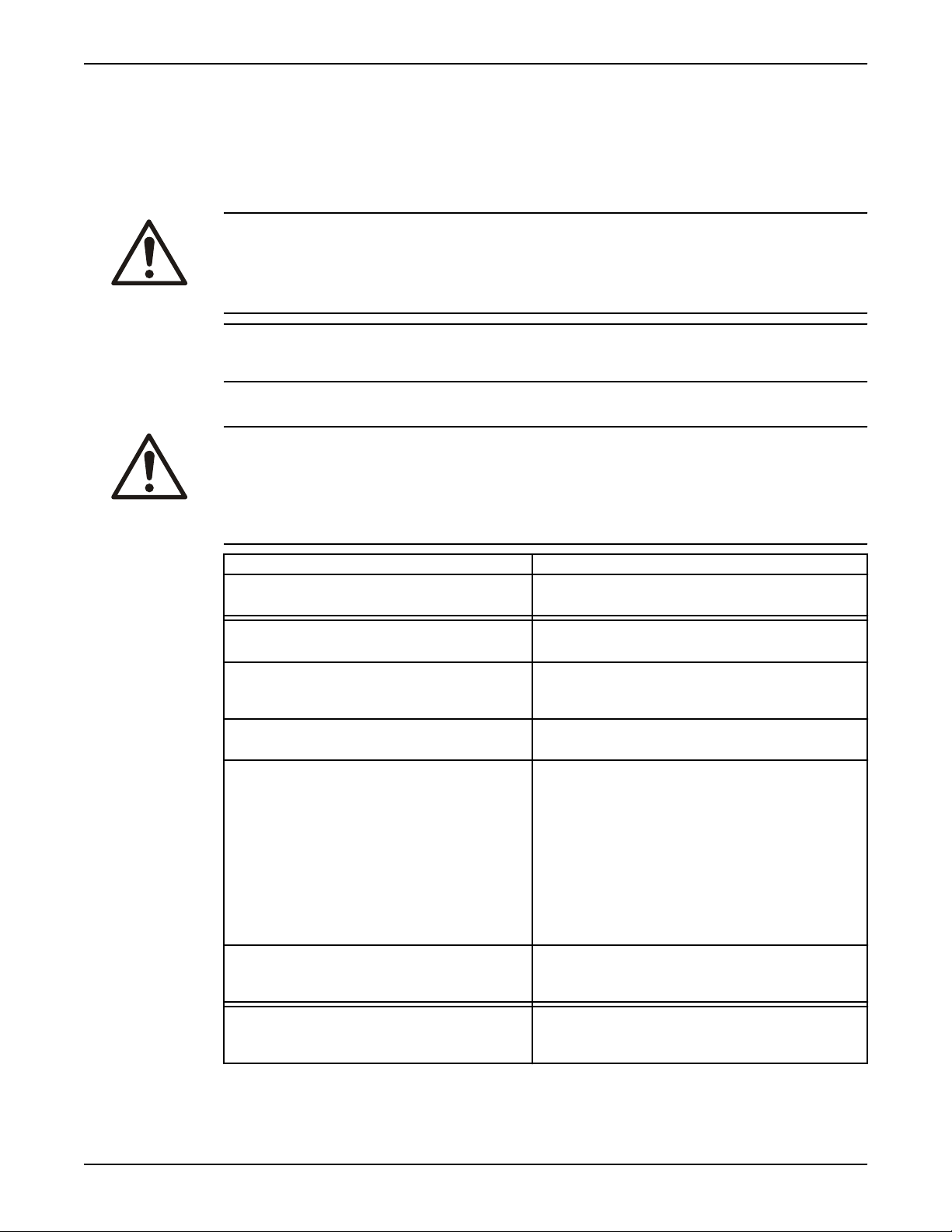
CAUTION:
Read this manual carefully before installing and using the product. Improper use of the product can cause
personal injury and damage to property, and may void the warranty.
NOTICE:
Save this manual for future reference, and keep it readily available at the location of the unit.
Requesting other information
Special versions can be supplied with supplementary instruction leaflets. See the sales contract for any
modifications or special version characteristics. For instructions, situations, or events that are not
considered in this manual or in the sales documents, please contact the nearest ITT representative.
Always specify the exact product type and identification code when requesting technical information or
spare parts.
Safety
WARNING:
• The operator must be aware of safety precautions to prevent physical injury.
• Any pressure-containing device can explode, rupture, or discharge its contents if it is over-pressurized.
Take all necessary measures to avoid over-pressurization.
• Operating, installing, or maintaining the unit in any way that is not covered in this manual could cause
death, serious personal injury, or damage to the equipment. This includes any modification to the
equipment or use of parts not provided by ITT. If there is a question regarding the intended use of
the equipment, please contact an ITT representative before proceeding.
• This manual clearly identify accepted methods for disassembling units. These methods must be
adhered to. Trapped liquid can rapidly expand and result in a violent explosion and injury. Never apply
heat to impellers, propellers, or their retaining devices to aid in their removal.
• Do not change the service application without the approval of an authorized ITT representative.
CAUTION:
You must observe the instructions contained in this manual. Failure to do so could result in physical injury,
damage, or delays.
4 Model IC, ICI, ICH, ICIH Installation, Operation, and Maintenance Manual
Page 7
Safety terminology and symbols
About safety messages
It is extremely important that you read, understand, and follow the safety messages and regulations
carefully before handling the product. They are published to help prevent these hazards:
• Personal accidents and health problems
• Damage to the product
• Product malfunction
Hazard levels
Hazard level Indication
DANGER:
WARNING:
Introduction and Safety
A hazardous situation which, if not avoided, will
result in death or serious injury
A hazardous situation which, if not avoided, could
result in death or serious injury
Hazard categories
A hazardous situation which, if not avoided, could
CAUTION:
NOTICE:
Hazard categories can either fall under hazard levels or let specific symbols replace the ordinary hazard
level symbols.
Electrical hazards are indicated by the following specific symbol:
Electrical Hazard:
These are examples of other categories that can occur. They fall under the ordinary hazard levels and may
use complementing symbols:
• Crush hazard
• Cutting hazard
• Arc flash hazard
result in minor or moderate injury
• A potential situation which, if not avoided,
could result in undesirable conditions
• A practice not related to personal injury
The Ex symbol
The Ex symbol indicates safety regulations for Ex-approved products when used in atmospheres that are
potentially explosive or flammable.
Model IC, ICI, ICH, ICIH Installation, Operation, and Maintenance Manual 5
Page 8

Introduction and Safety
Environmental safety
The work area
Always keep the station clean to avoid and/or discover emissions.
Waste and emissions regulations
Observe these safety regulations regarding waste and emissions:
• Appropriately dispose of all waste.
• Handle and dispose of the processed liquid in compliance with applicable environmental regulations.
• Clean up all spills in accordance with safety and environmental procedures.
• Report all environmental emissions to the appropriate authorities.
Electrical installation
For electrical installation recycling requirements, consult your local electric utility.
Recycling guidelines
Always follow local laws and regulations regarding recycling.
User safety
General safety rules
These safety rules apply:
• Always keep the work area clean.
• Pay attention to the risks presented by gas and vapors in the work area.
• Avoid all electrical dangers. Pay attention to the risks of electric shock or arc flash hazards.
• Always bear in mind the risk of drowning, electrical accidents, and burn injuries.
Safety equipment
Electrical connections
Wash the skin and eyes
Use safety equipment according to the company regulations. Use this safety equipment within the work
area:
• Helmet
• Safety goggles, preferably with side shields
• Protective shoes
• Protective gloves
• Gas mask
• Hearing protection
• First-aid kit
• Safety devices
NOTICE:
Never operate a unit unless safety devices are installed. Also see specific information about safety
devices in other chapters of this manual.
Electrical connections must be made by certified electricians in compliance with all international, national,
state, and local regulations. For more information about requirements, see sections dealing specifically with
electrical connections.
Do the following if chemicals or hazardous fluids have come into contact with your eyes or your skin:
6 Model IC, ICI, ICH, ICIH Installation, Operation, and Maintenance Manual
Page 9

Introduction and Safety
If you need to wash
your...
Eyes
Skin
Then...
1. Hold your eyelids apart forcibly with your fingers.
2. Rinse the eyes with eyewash or running water for at least 15 minutes.
3. Seek medical attention.
1. Remove contaminated clothing.
2. Wash the skin with soap and water for at least one minute.
3. Seek medical attention, if required.
Ex-approved products
Follow these special handling instructions if you have an Ex-approved unit.
Personnel requirements
These are the personnel requirements for Ex-approved products in potentially explosive atmospheres:
• All work on the product must be carried out by certified electricians and ITT-authorized mechanics.
Special rules apply to installations in explosive atmospheres.
• All users must know about the risks of electric current and the chemical and physical characteristics of
the gas, the vapor, or both present in hazardous areas.
• Any maintenance for Ex-approved products must conform to international and national standards
(for example, IEC/EN 60079-17).
ITT disclaims all responsibility for work done by untrained and unauthorized personnel.
Product and product handling requirements
These are the product and product handling requirements for Ex-approved products in potentially
explosive atmospheres:
• Only use the product in accordance with the approved motor data.
• The Ex-approved product must never run dry during normal operation. Dry running during service
and inspection is only permitted outside the classified area.
• Before you start work on the product, make sure that the product and the control panel are isolated
from the power supply and the control circuit, so they cannot be energized.
• Do not open the product while it is energized or in an explosive gas atmosphere.
• Make sure that thermal contacts are connected to a protection circuit according to the approval
classification of the product, and that they are in use.
• Intrinsically safe circuits are normally required for the automatic level-control system by the level
regulator if mounted in zone 0.
• The yield stress of fasteners must be in accordance with the approval drawing and the product
specification.
• Do not modify the equipment without approval from an authorized ITT representative.
• Only use parts that are provided by an authorized ITT representative.
Description of ATEX
The ATEX directives are a specification enforced in Europe for electrical and non-electrical equipment
installed in Europe. ATEX deals with the control of potentially explosive atmospheres and the standards
of equipment and protective systems used within these atmospheres. The relevance of the ATEX
requirements is not limited to Europe. You can apply these guidelines to equipment installed in any
potentially explosive atmosphere.
Guidelines for compliance
Compliance is fulfilled only when you operate the unit within its intended use. Do not change the
conditions of the service without the approval of an ITT representative. When you install or maintain
explosion proof products, always comply with the directive and applicable standards (for example, IEC/
EN 60079–14).
Model IC, ICI, ICH, ICIH Installation, Operation, and Maintenance Manual 7
Page 10

Introduction and Safety
Product warranty
Coverage
ITT undertakes to remedy faults in products from ITT under these conditions:
• The faults are due to defects in design, materials, or workmanship.
• The faults are reported to an ITT representative within the warranty period.
• The product is used only under the conditions described in this manual.
• The monitoring equipment incorporated in the product is correctly connected and in use.
• All service and repair work is done by ITT-authorized personnel.
• Genuine ITT parts are used.
• Only Ex-approved spare parts and accessories authorized by ITT are used in Ex-approved products.
Limitations
The warranty does not cover faults caused by these situations:
• Deficient maintenance
• Improper installation
• Modifications or changes to the product and installation made without consulting ITT
• Incorrectly executed repair work
• Normal wear and tear
ITT assumes no liability for these situations:
• Bodily injuries
• Material damages
• Economic losses
Warranty claim
ITT products are high-quality products with expected reliable operation and long life. However, should the
need arise for a warranty claim, then contact your ITT representative.
8 Model IC, ICI, ICH, ICIH Installation, Operation, and Maintenance Manual
Page 11
Transportation and Storage
Inspect the delivery
Inspect the package
1. Inspect the package for damaged or missing items upon delivery.
2. Note any damaged or missing items on the receipt and freight bill.
3. File a claim with the shipping company if anything is out of order.
If the product has been picked up at a distributor, make a claim directly to the distributor.
Inspect the unit
1. Remove packing materials from the product.
Dispose of all packing materials in accordance with local regulations.
2. Inspect the product to determine if any parts have been damaged or are missing.
3. If applicable, unfasten the product by removing any screws, bolts, or straps.
For your personal safety, be careful when you handle nails and straps.
4. Contact your sales representative if anything is out of order.
Transportation and Storage
Transportation guidelines
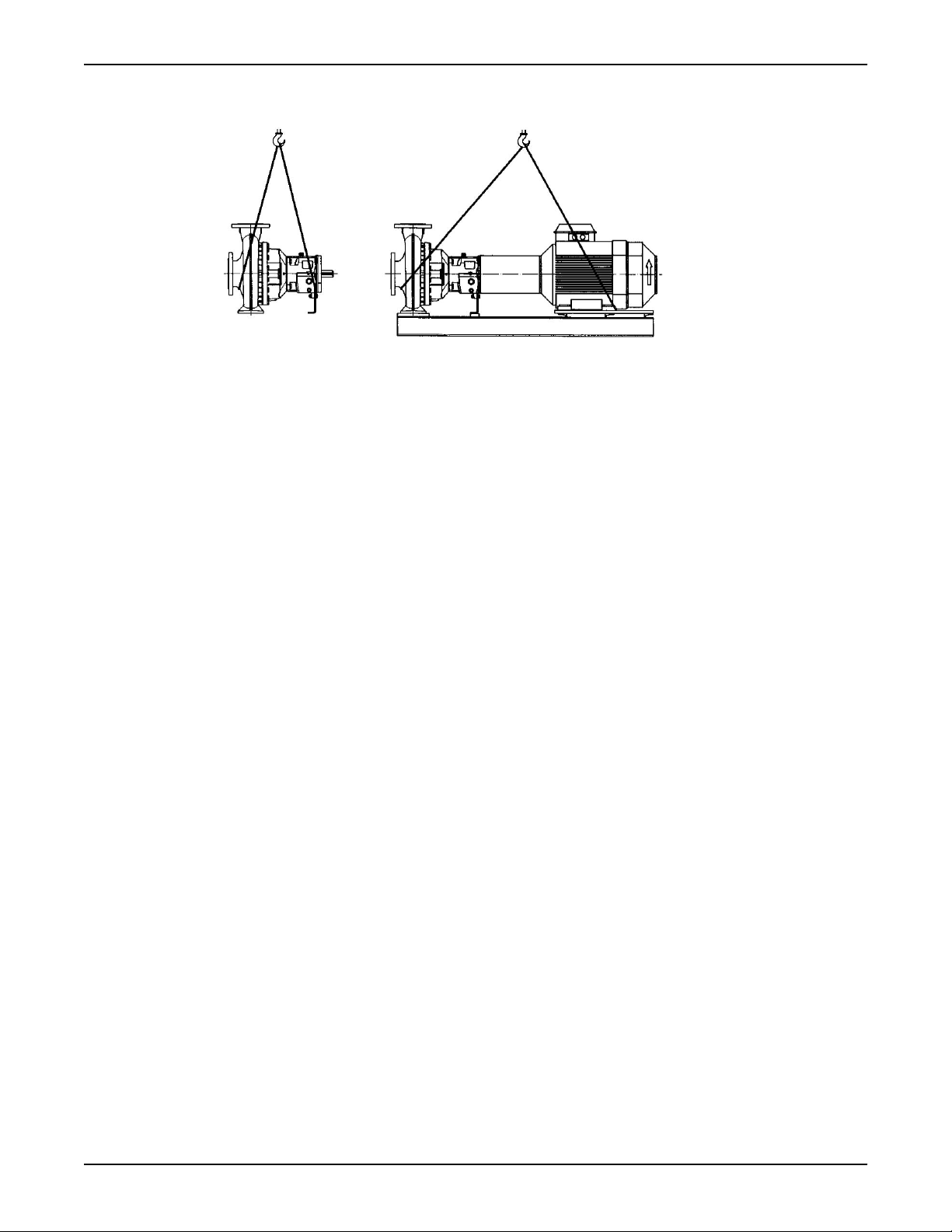
Pump handling and lifting
Precautions for moving the pump
Use care when moving pumps.
WARNING:
Make sure that the pump cannot roll or fall over and injure people or damage property.
NOTICE:
Use a forklift truck with sufficient capacity to move the pallet with the pump unit on top.
Keep the pump unit in the same position in which it was shipped from the factory.
Close the suction and discharge ends of the pump with plugs for transport and storage.
Precautions for lifting the pump
WARNING:
Crush hazard. The unit and the components can be heavy. Use proper lifting methods and wear steel-toed
shoes at all times.
NOTICE:
• Make sure that the lifting equipment supports the entire assembly and is only used by authorized
personnel.
• Do not attach sling ropes to shaft ends.
Model IC, ICI, ICH, ICIH Installation, Operation, and Maintenance Manual 9
Page 12
Transportation and Storage
Lifting the pump
Hoist the pump using a suitable sling under solid points such as the casing, flanges, or frame.
Storage guidelines
Long-term storage
If the pump is stored for more than 6 months, these requirements apply:
• Store in a covered and dry location.
• Store the unit free from heat, dirt, and vibrations.
• Rotate the shaft by hand several times at least every three months.
Treat bearing and machined surfaces so that they are well preserved. Refer to the drive unit and coupling
manufacturers for their long-term storage procedures.
For questions about possible long-term storage treatment services, please contact your local ITT sales
representative.
10 Model IC, ICI, ICH, ICIH Installation, Operation, and Maintenance Manual
Page 13
Product Description
General description
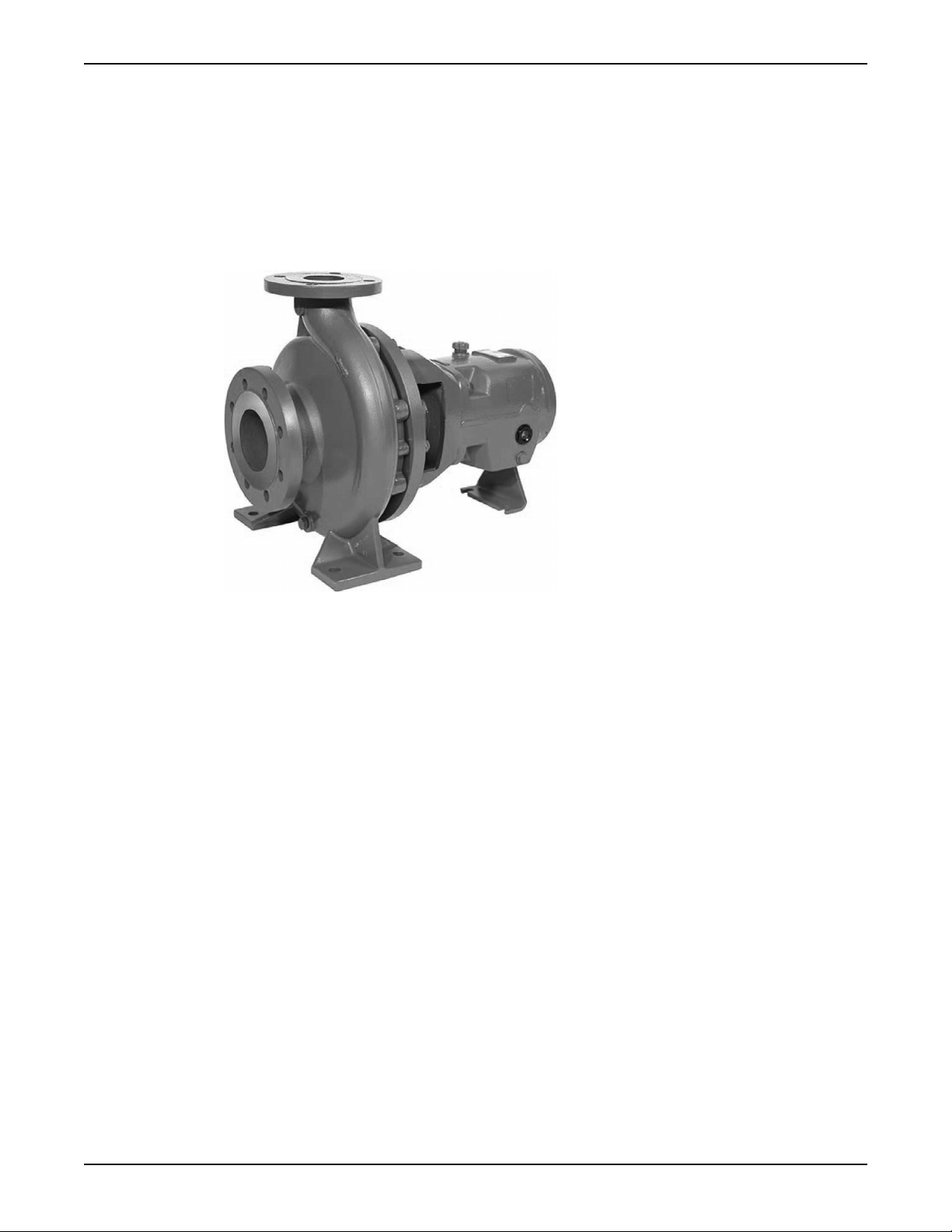
The model IC is a single-stage volute casing pump. Hydraulic design and dimensions comply with ISO
2858/ EN 22858. The technical design complies with ISO 5199/EN 25199. The model ICI additionally
has an inducer. Models ICH and ICIH additionally have cooling or heating of the casing cover and/or the
volute casing.
Product Description
Casing
Impeller
Seal chamber
Power end
Frame adapter
• Heavy-duty, top centerline discharge
• Integral cast feet
• Back pullout design
• Standard 3/8 in. NPT casing drain
• Optional renewable wear ring
The impeller is fully enclosed and key driven by the shaft. Standard back vanes or balance holes reduce
axial thrust and seal chamber pressures.
• Wide choice of sealing arrangements for maximum sealing flexibility
• Patented “cyclone” seal chamber for improved lubrication, heat removal, and solids handling
• Confined casing gasket
• Large capacity oil sump reduces oil temperature for extended bearing life.
• Heavy-duty cast iron frame gives rigid support to the shaft and bearings for longer service.
• Magnetic drain plug maintains a clean oil environment for extended bearing life.
• Standard double lip seals at the pump and coupling end maintain a seal tight, clean operating
environment.
• O-ring seal between the frame and adapter for optimized alignment and sealing.
• Provides safe and accurate alignment for the liquid end to the bearing frame.
• Large access windows make installation and maintenance of seal and auxiliary support systems
trouble-free.
Model IC, ICI, ICH, ICIH Installation, Operation, and Maintenance Manual 11
Page 14
Product Description
Bearings
Heavy-duty ball bearings provide L10 bearing life in excess of 17,500 hours.
The size of the bearing bracket is shown in the data sheet and/or order confirmation.
Bearing bracket Bearing type
24 6307 - C3 3307A - C3
32 6309 - C3 3309A - C3
42 6311 - C3 3311A - C3
48 6313 - C3 3313A - C3
Shaft
Rigid shaft designed for less than 0.05 mm shaft deflection. Standard 400 series stainless steel shaft
(1.4021) provides reliable power transmission and corrosion resistance at both the pump and coupling
ends.
Intended applications
• ISO chemical process
• Industrial process
Nameplate information
Pump side Drive side
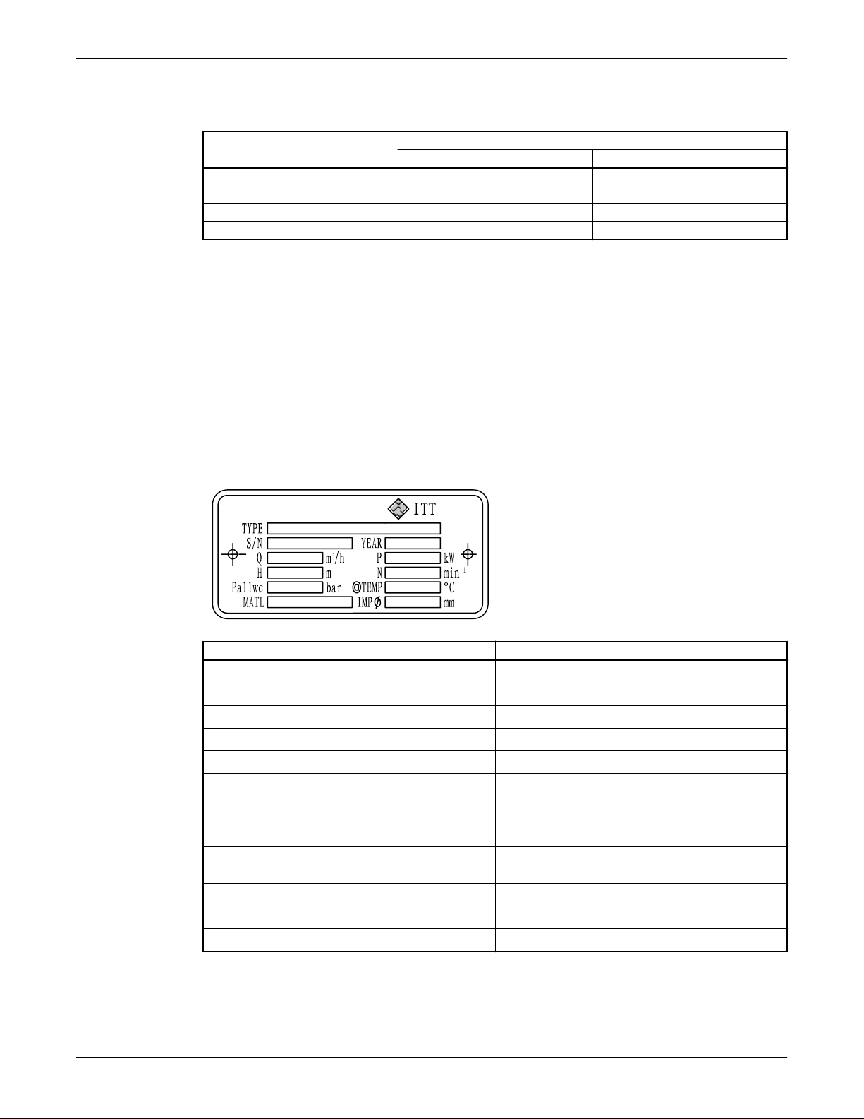
Pump nameplate
Nameplate field Explanation
Type* Type of pump
S/N* Serial number
Q Rated pump flow, in cubic meters per hour
P Rated pump power, in kilowatts
H Rated pump head, in meters
n Rated pump speed, in min
P
all w C
Maximum permitted casing-operation-pressure
-1
(Highest discharge pressure at the rated operating
temperature to which the pump casing can be used)
t
max op
Maximum permitted operating temperature of
pumped liquid
Item No Customer-related order number
Imp Ø Outer diameter of the impeller
MATL Material of construction
*All details of design and materials are defined with this information. You must specify these details when
you order spare parts.
12 Model IC, ICI, ICH, ICIH Installation, Operation, and Maintenance Manual
Page 15
ATEX nameplate
Product Description
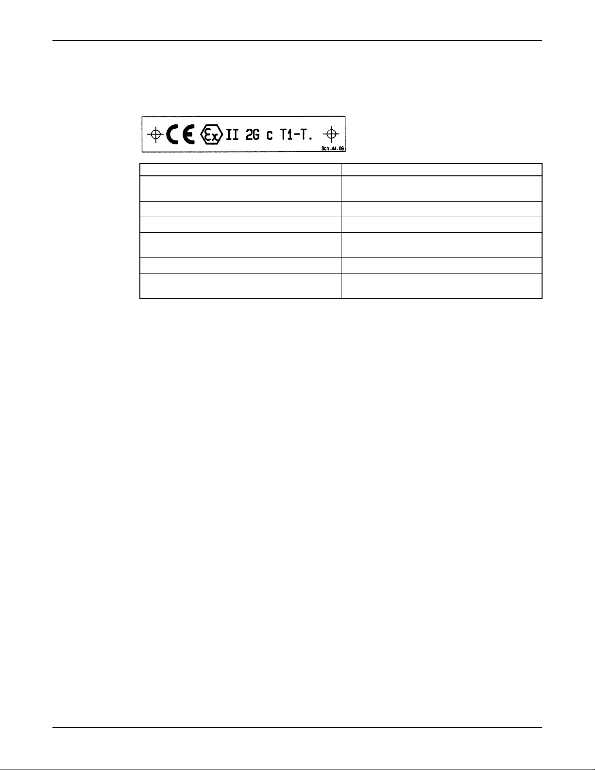
The conformity with the EC directive 94/9/EG "Appliances and Protection Systems for designated use in
areas endangered to explosion" is declared by the issue of the EC Declaration of Conformity and the
attachment of the ATEX label on the bearing bracket of the pump. The ATEX label is also attached to the
pump nameplate.
Nameplate field Explanation
CE Marking of compliance with the EC directive 94/9/
EG
Ex Specific marking for explosion protection
II Appliance group
2G Category (2) and explosive atmosphere due to gases,
vapors, or mist (G)
c ignition protection in use: constructual safety (c)
T1-T. Classification of the theoretically available range of
the temperature classes
Model IC, ICI, ICH, ICIH Installation, Operation, and Maintenance Manual 13
Page 16
Installation
Installation
Preinstallation
Precautions
WARNING:
• When installing in a potentially explosive environment, make sure that the motor is properly certified.
• You must earth (ground) all electrical equipment. This applies to the pump equipment, the driver, and
any monitoring equipment. Test the earth (ground) lead to verify that it is connected correctly.
NOTICE: Supervision by an authorized ITT representative is recommended to ensure proper installation.
Failure to do so may result in equipment damage or decreased performance.
Pump location guidelines
WARNING:
Assembled units and their components are heavy. Failure to properly lift and support this equipment can
result in serious physical injury and/or equipment damage. Lift equipment only at the specifically identified
lifting points. Lifting devices such as eyebolts, slings, and spreaders must be rated, selected, and used for
the entire load being lifted.
Guideline Explanation/comment
Keep the pump as close to the liquid source as
practically possible.
Make sure that the space around the pump is
sufficient.
If you require lifting equipment such as a hoist or
tackle, make sure that there is enough space above
the pump.
Protect the unit from weather and water damage
due to rain, flooding, and freezing temperatures.
Do not install and operate the equipment in
closed systems unless the system is constructed
with properly-sized safety devices and control
devices.
Take into consideration the occurrence of
unwanted noise and vibration.
This minimizes the friction loss and keeps the suction
piping as short as possible.
This facilitates ventilation, inspection, maintenance,
and service.
This makes it easier to properly use the lifting
equipment and safely remove and relocate the
components to a safe location.
This is applicable if nothing else is specified.
Acceptable devices:
• Pressure relief valves
• Compression tanks
• Pressure controls
• Temperature controls
• Flow controls
If the system does not include these devices, consult
the engineer or architect in charge before you operate
the pump.
The best pump location for noise and vibration
absorption is on a concrete floor with subsoil
underneath.
If the pump location is overhead, undertake
special precautions to reduce possible noise
transmission.
14 Model IC, ICI, ICH, ICIH Installation, Operation, and Maintenance Manual
Consider a consultation with a noise specialist.
Page 17
Foundation requirements
1
2
3
4
5
6
1
3
2
4
5
Requirements
• The foundation must be able to absorb any type of vibration and form a permanent, rigid support for
the pump unit.
• The location and size of the foundation bolt holes must match those shown on the assembly drawing
provided with the pump data package.
• The foundation must weigh between two and three times the weight of the pump.
• Provide a flat, substantial concrete foundation in order to prevent strain and distortion when you
tighten the foundation bolts.
• Sleeve-type and J-type foundation bolts are most commonly used. Both designs allow movement for
the final bolt adjustment.
• The concrete foundation must have sufficient firmness according to DIN 1045 or equal standard.
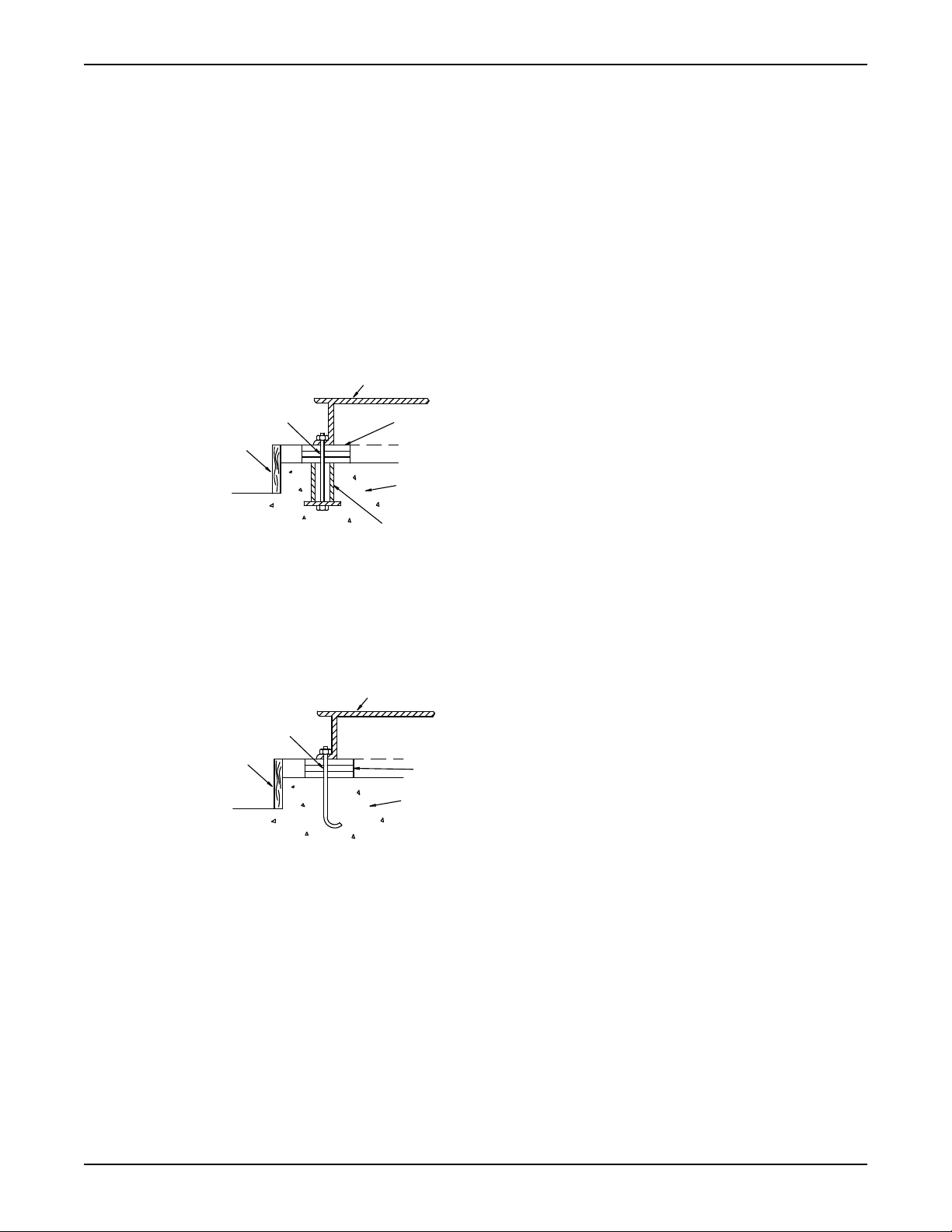
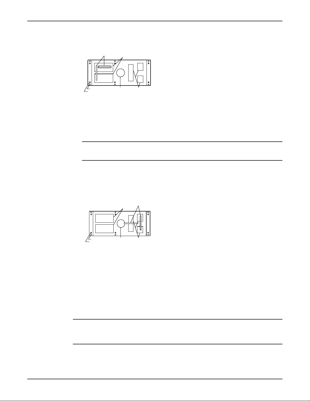
Sleeve-type bolts
Installation
1. Baseplate
2. Shims or wedges
3. Foundation
4. Sleeve
5. Dam
6. Bolt
J-type bolts
1. Baseplate
2. Shims or wedges
3. Foundation
4. Dam
5. Bolt
Baseplate-mounting procedures
Prepare the baseplate for mounting
1. Remove all the attached equipment from the baseplate.
2. Clean the underside of the baseplate completely.
Model IC, ICI, ICH, ICIH Installation, Operation, and Maintenance Manual 15
3. If applicable, coat the underside of the baseplate with an epoxy primer.
Use an epoxy primer only if you used an epoxy-based grout.
4. Remove the rust-proofing coat from the machined mounting pads using an appropriate solvent.
5. Remove water and debris from the foundation-bolt holes.
Page 18
1
1
Installation
Prepare the foundation for mounting
1. Chip the top of the foundation to a minimum of 1.0 in. (25.0 mm) in order to remove porous or lowstrength concrete.
If you use a pneumatic hammer, make sure that it does not contaminate the surface with oil or other
moisture.
NOTICE: Do not chip the foundation using heavy tools such as jackhammers. This can damage the
structural integrity of the foundation.
2. Remove water or debris from the foundation bolt holes or sleeves.
3. If the baseplate uses sleeve-type bolts, then fill the sleeves with a non-binding, moldable material. Seal
the sleeves in order to prevent the grout from entering.
4. Coat the exposed portion of the anchor bolts with a non-bonding compound such as paste wax in
order to prevent the grout from adhering to the anchor bolts.
Do not use oils or liquid wax.
5. If recommended by the grout manufacturer, coat the foundation surface with a compatible primer.
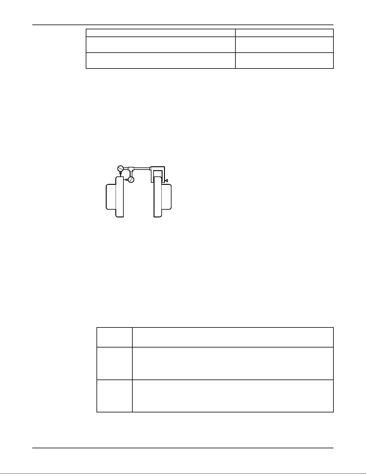
Install the baseplate using shims or wedges
Required tools:
• Two sets of shims or wedges for each foundation bolt
• Two machinist's levels
• Baseplate-leveling worksheet
This procedure is applicable to cast iron and fabricated steel baseplates.
1. If you use sleeve-type bolts, fill the bolt sleeves with packing material or rags to prevent grout from
entering the bolt holes.
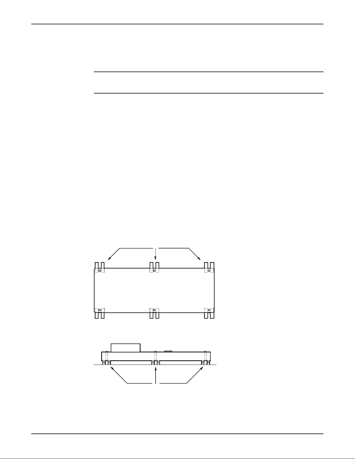
2. Put the sets of wedges or shims on each side of each foundation bolt.
The sets of wedges should have a height of between 0.75 in. (19 mm) and 1.50 in. (38 mm).
1. Shims or wedges
Figure 1: Top view
1. Shims or wedges
Figure 2: Side view
3. Lower the baseplate carefully onto the foundation bolts.
4. Put the machinist's levels across the mounting pads of the driver and the mounting pads of the pump.
16 Model IC, ICI, ICH, ICIH Installation, Operation, and Maintenance Manual
Page 19
NOTICE: Remove all dirt from the mounting pads in order to make sure that you achieve the
1
2
3
4
correct leveling. Failure to do so can result in equipment damage or decreased performance.
5. Level the baseplate both lengthwise and across by adding or removing shims or moving the wedges.
These are the leveling tolerances:
• A maximum difference of 0.125 in. (3.2 mm) lengthwise
• A maximum difference of 0.059 in. (1.5 mm) across
You can use the baseplate-leveling worksheet when you take the readings.
6. Hand-tighten the nuts for the foundation.
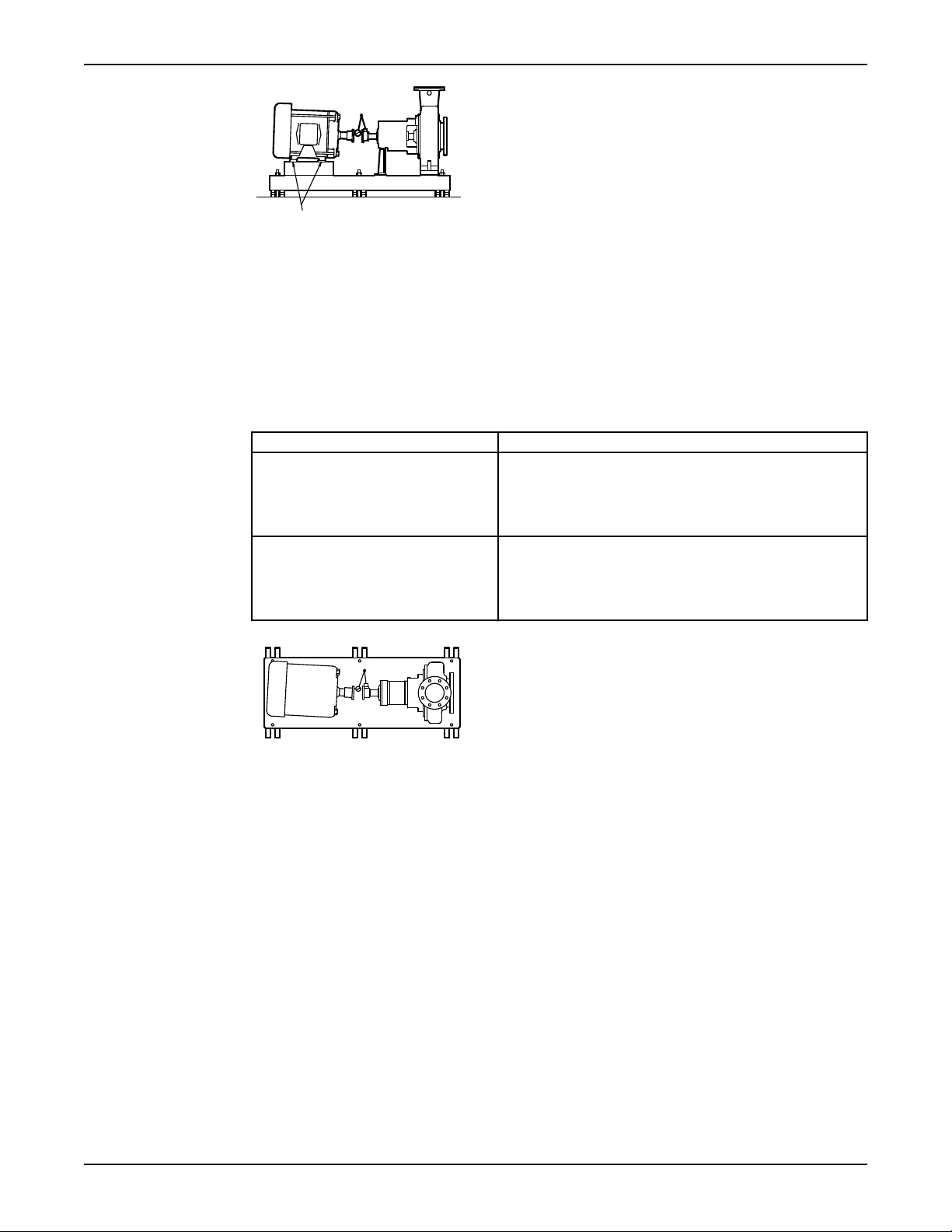
Install the baseplate using jackscrews
Tools required:
• Anti-seize compound
• Jackscrews
• Bar stock
• Two machinist's levels
• Baseplate-leveling worksheet
This procedure is applicable to the feature-fabricated steel baseplate and the advantage base baseplate.
1. Apply an anti-seize compound on the jackscrews.
The compound makes it easier to remove the screws after you grout.
2. Lower the baseplate carefully onto the foundation bolts and perform these steps:
a) Cut the plates from the bar stock and chamfer the edges of the plates in order to reduce stress
concentrations.
b) Put the plates between the jackscrews and the foundation surface.
c) Use the four jackscrews in the corners in order to raise the baseplate above the foundation.
Make sure that the distance between the baseplate and the foundation surface is between 0.75 in.
(19 mm) and 1.50 in. (38 mm).
d) Make sure that the center jackscrews do not touch the foundation surface yet.
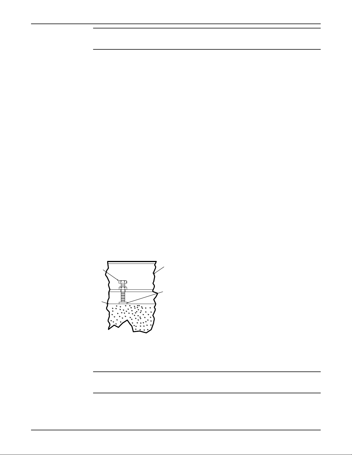
Installation
1. Jackscrew
2. Baseplate
3. Foundation
4. Plate
3. Level the driver mounting pads:
NOTICE: Remove all dirt from the mounting pads in order to make sure that you achieve the
correct leveling. Failure to do so can result in equipment damage or decreased performance.
a) Put one machinist's level lengthwise on one of the two pads.
Model IC, ICI, ICH, ICIH Installation, Operation, and Maintenance Manual 17
b) Put the other machinist's level across the ends of the two pads.
c) Level the pads by adjusting the four jackscrews in the corners.
Page 20
1
2
3
4
5
6
1
2
3
4
5
6
Installation
Make sure that the machinist's level readings are as close to zero as possible, both lengthwise and
across.
Use the baseplate-leveling worksheet when you take the readings.
1. Machinist's levels
2. Driver's mounting pads
3. Foundation bolts
4. Jackscrews
5. Grout hole
6. Pump's mounting pads
4. Turn the center jackscrews down so that they rest on their plates on the foundation surface.
5. Level the pump mounting pads:
NOTICE: Remove all dirt from the mounting pads in order to make sure that you achieve the
correct leveling. Failure to do so can result in equipment damage or decreased performance.
a) Put one machinist's level lengthwise on one of the two pads.
b) Put the other level across the center of the two pads.
c) Level the pads by adjusting the four jackscrews in the corners.
Make sure that the machinist's level readings are as close to zero as possible, both lengthwise and
across.
1. Driver's mounting pads
2. Machinist's levels
3. Foundation bolts
4. Jackscrews
5. Grout hole
6. Pump's mounting pads
6. Hand-tighten the nuts for the foundation bolts.
7. Check that the driver's mounting pads are level and adjust the jackscrews and the foundation bolts if
necessary.
The correct level measurement is a maximum of 0.002 in./ft (0.0167 mm/m).
Install the baseplate using spring mounting
NOTICE: The spring-mounted baseplate is designed only to support piping loads from thermal
expansion. You must support the suction and discharge piping individually. Failure to do so may result in
equipment damage.
The foundation pads are not provided with the baseplate. Make sure that the foundation pads are 316
18 Model IC, ICI, ICH, ICIH Installation, Operation, and Maintenance Manual
stainless-steel plates, which have a 16-20 micro-inch surface finish.
Before you start this procedure, make sure that the foundation pads are correctly installed on the
foundation/floor (see the manufacturer's instructions).
Page 21
1. Put the baseplate on a support above the foundation/floor.
1
2
3
4
5
6
7
Make sure that there is enough space between the baseplate and the foundation/floor in order to
install the spring assemblies.
2. Install the lower part of the spring assembly:
a) Screw the lower jam nut onto the spring stud.
b) Screw the lower adjusting nut onto the spring-stud, on top of the jam nut.
c) Set the lower adjusting nut to the correct height.
The correct height depends on the required distance between the foundation/floor and the
baseplate.
d) Put a washer, a follower, a spring, and one more follower onto the lower adjusting nut.
3. Install the spring assembly on the baseplate:
a) Insert the spring assembly into the baseplate's anchorage hole from below.
b) Put a follower, a spring, another follower, and a washer onto the spring stud.
c) Fasten the spring assembly with the upper adjusting nut by hand.
4. Thread the upper jam nut onto the spring stud by hand.
5. Repeat steps 2 through 4 for all the spring assemblies.
6. Lower the baseplate so that the spring assemblies fit into the foundation pads.
7. Level the baseplate and make the final height adjustments:
a) Loosen the upper jam nuts and adjusting nuts.
b) Adjust the height and level the baseplate by moving the lower adjusting nuts.
c) When the baseplate is level, tighten the top adjusting nuts so that the top springs are not loose in
their followers.
8. Fasten the lower and upper jam nuts on each spring assembly.
Installation
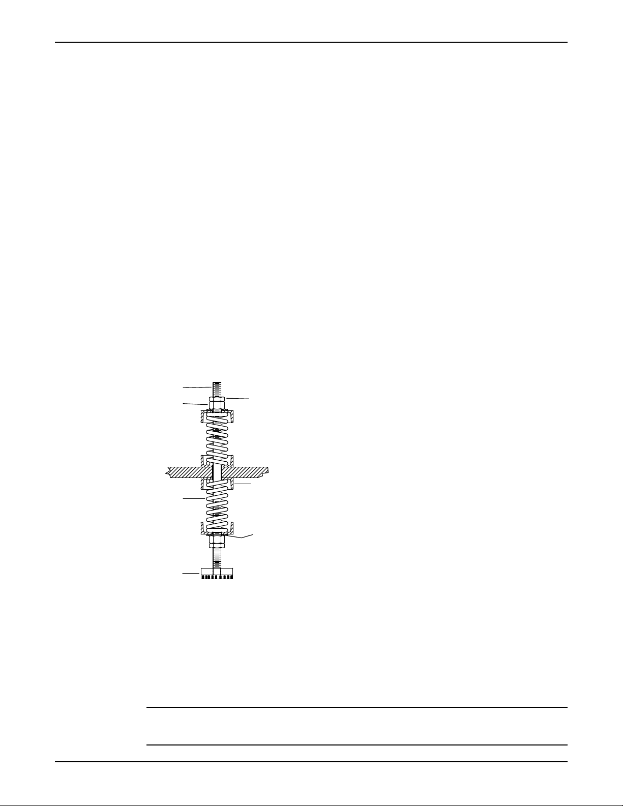
Install the baseplate using stilt mounting
1. Upper jam nut
2. Follower
3. Washer
4. Foundation pads
5. Spring
6. Upper adjusting nut
7. Spring stud
Figure 3: Example of an installed spring assembly
NOTICE: The stilt-mounted baseplate is not designed to support static piping loads. Make sure to
individually support the suction and discharge piping. Failure to do so may result in equipment damage.
Model IC, ICI, ICH, ICIH Installation, Operation, and Maintenance Manual 19
Page 22
1
2
3
4
5
6
7
8
Installation
1. Put the baseplate on a support above the foundation/floor.
Make sure that there is enough space between the baseplate and the foundation/floor to install the
stilts.
2. Install the lower part of the stilt assembly:
a) Screw the lower jam nut and adjusting nut onto the stilt.
b) Set the lower adjusting nut to the correct height.
The correct height depends on the required distance between the foundation/floor and the
baseplate.
c) Put a washer onto the lower adjusting- nut.
3. Install the stilt assembly on the baseplate:
a) Insert the stilt assembly into the baseplate's anchorage hole from below.
b) Put a washer onto the stilt.
c) Fasten the stilt assembly with the upper adjusting nut by hand.
4. Screw the upper jam nut onto the stilt by hand.
5. Repeat steps 2 through 4 for all the stilt assemblies.
6. Lower the baseplate so that the stilts fit into the foundation cups.
7. Level the baseplate and make the final height adjustments:
a) Loosen the upper jam nuts and adjusting nuts.
b) Adjust the height and level the baseplate by moving the lower adjusting nuts.
c) When the baseplate is level, tighten the top adjusting nuts.
8. Fasten the lower and upper jam nuts on each stilt.
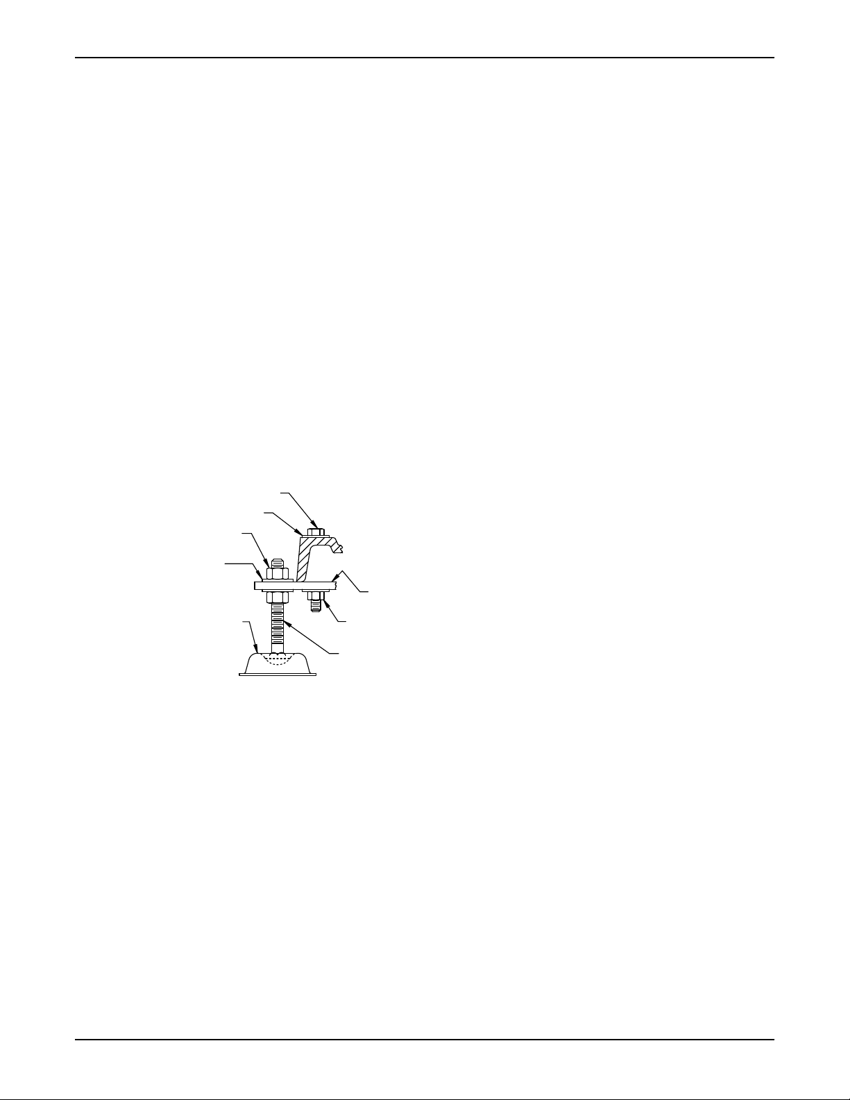
1. Mounting plate
2. Mounting nut
3. Stilt bolt
4. Foundation cups
5. Washer
6. Upper adjustment nut
7. Mounting washer
8. Mounting bolt
Figure 4: Example of an installed stilt assembly
20 Model IC, ICI, ICH, ICIH Installation, Operation, and Maintenance Manual
Page 23
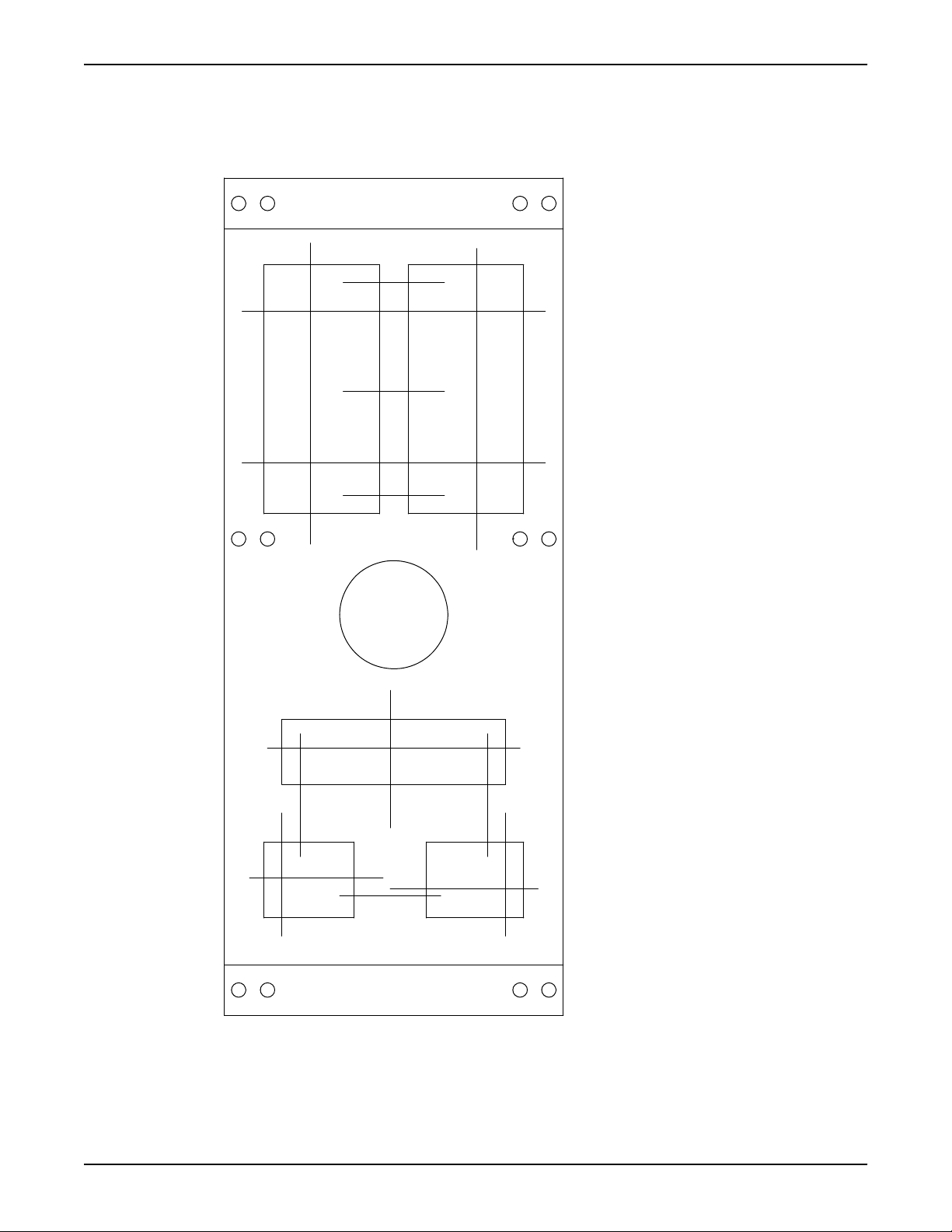
Baseplate-leveling worksheet
1
2
3
4
5
6
7
8
9
10
11
12
13
14
15
16
17
18
1)____________________
2)____________________
3)____________________
4)____________________
5)____________________
6)____________________
7)____________________
8)____________________
9)____________________
10)___________________
11)___________________
12)___________________
13)___________________
14)___________________
15)___________________
16)___________________
17)___________________
18)___________________
Level measurements
Installation
Model IC, ICI, ICH, ICIH Installation, Operation, and Maintenance Manual 21
Page 24
Installation
Install the pump, driver, and coupling
1. Mount and fasten the pump on the baseplate. Use applicable bolts.
2. Mount the driver on the baseplate. Use applicable bolts and hand tighten.
3. Install the coupling.
See the installation instructions from the coupling manufacturer.
Pump-to-driver alignment
Precautions
WARNING:
• Follow shaft alignment procedures in order to prevent catastrophic failure of drive components or
unintended contact of rotating parts. Follow the coupling installation and operation procedures from
the coupling manufacturer.
• Always disconnect and lock out power to the driver before you perform any installation or
maintenance tasks. Failure to disconnect and lock out driver power will result in serious physical
injury.
NOTICE: Proper alignment is the responsibility of the installer and the user of the unit. Check the
alignment of frame-mounted units before you operate the unit. Failure to do so can result in equipment
damage or decreased performance.
Alignment checks
When to perform alignment checks
You must perform alignment checks under these circumstances:
• The process temperature changes.
• The piping changes.
• The pump has been serviced.
Types of alignment checks
Type of check When it is used
Initial alignment (cold alignment)
check
Final alignment (hot alignment)
check
Initial alignment (cold alignment) checks
When Why
Before you grout the baseplate This ensures that alignment can be accomplished.
After you grout the baseplate This ensures that no changes have occurred during the grouting
After you connect the piping This ensures that pipe strains have not altered the alignment.
Prior to operation when the pump and the driver are at ambient
temperature.
After operation when the pump and the driver are at operating
temperature.
process.
If changes have occurred, you must alter the piping to remove pipe
strains on the pump flanges.
Final alignment (hot alignment) checks
When Why
After the first run This ensures correct alignment when both the pump and the driver
are at operating temperature.
22 Model IC, ICI, ICH, ICIH Installation, Operation, and Maintenance Manual
Page 25

When Why
Periodically This follows the plant operating procedures.
Permitted indicator values for alignment checks
NOTICE: The specified permitted reading values are valid only at operating temperature. For cold
settings, other values are permitted. You must use the correct tolerances. Failure to do so can result in
misalignment and reduced pump reliability.
IMPORTANT
• For electric motors, the motor shaft initial (cold) parallel vertical alignment setting should be 0.002 to
0.004 in. (0.05 to 0.10 mm) lower than the pump shaft.
• For other drivers such as turbines and engines, follow the driver manufacturer's recommendations.
When dial indicators are used to check the final alignment, the pump and drive unit are correctly aligned
when these conditions are true:
• The total indicator runout is a maximum of 0.002 in. (0.05 mm) at operating temperature.
• The tolerance of the indicator is 0.0005 in./in. (0.0127 mm/mm) of indicator separation at operating
temperature.
Cold settings for parallel vertical alignment
Introduction
This section shows the recommended preliminary (cold) settings for electric motor-driven pumps based on
different temperatures of pumped fluid. Consult driver manufacturers for recommended cold settings for
other types of drivers such as steam turbines and engines.
Installation
NOTICE: For electric motors, the motor shaft setting should be 0.002–0.004 in (0.05–0.1 mm) lower
than the pump shaft. For other drivers, follow the driver manufacturer's recommendations.
Recommended settings
Pumpage temperature Recommended setting
50°F (10°C) 0.002 in. (0.05 mm), low
150°F (65°C) 0.001 in. (0.03 mm), high
250°F (120°C) 0.005 in. (0.12 mm), high
350°F (175°C) 0.009 in. (0.23 mm), high
450°F (218°C) 0.013 in. (0.33 mm), high
550°F (228°C) 0.017 in. (0.43 mm), high
650°F (343°C) 0.021 in. (0.53 mm), high
700°F (371°C) 0.023 in. (0.58 mm), high
Alignment measurement guidelines
Guideline Explanation
Rotate the pump coupling half and the driver coupling half
together so that the indicator rods have contact with the same
points on the driver coupling half.
Move or shim only the driver in order to make adjustments. This prevents strain on the piping
Make sure that the hold-down bolts for the driver feet are tight
when you take indicator measurements.
This prevents incorrect measurement.
installations.
This keeps the driver stationary since
movement causes incorrect
measurement.
Model IC, ICI, ICH, ICIH Installation, Operation, and Maintenance Manual 23
Page 26
P
A
Y
X
Installation
Guideline Explanation
Make sure that the hold-down bolts for the driver feet are loose
before you make alignment corrections.
Check the alignment again after any mechanical adjustments. This corrects any misalignments that an
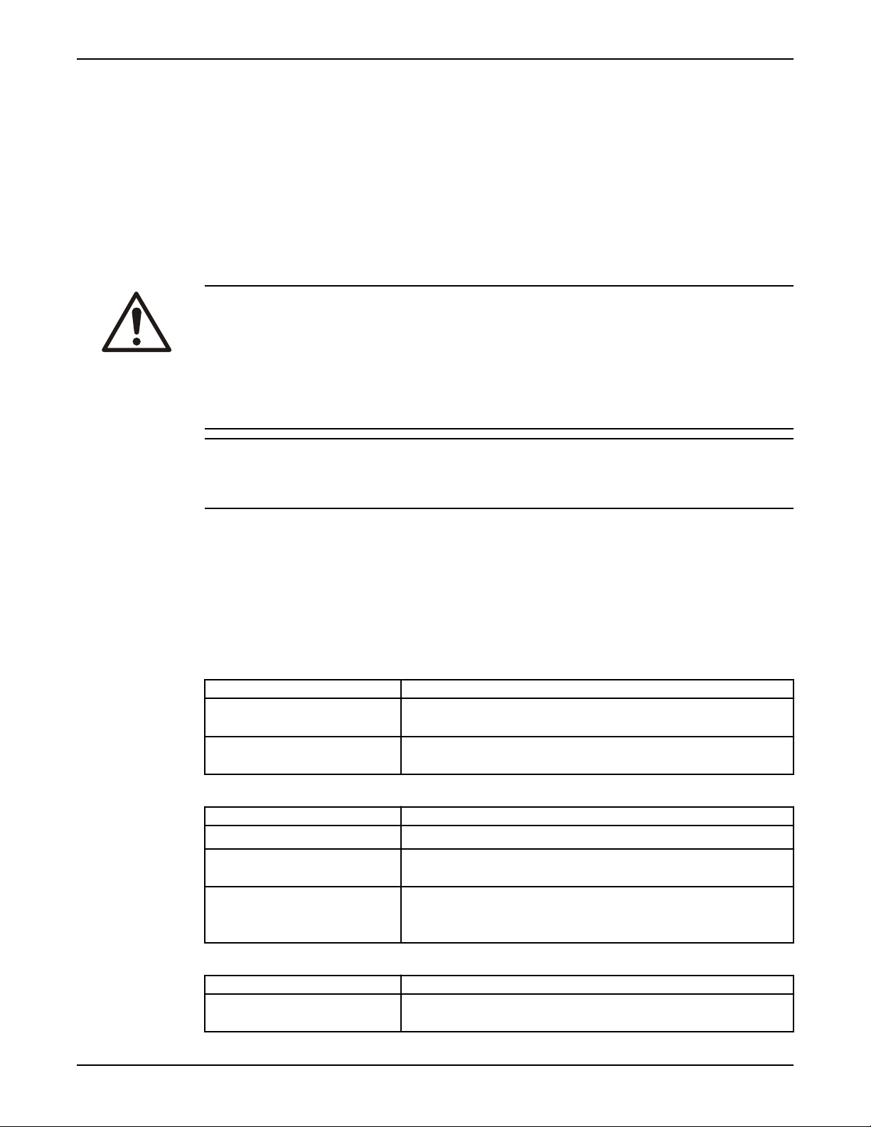
Attach the dial indicators for alignment
You must have two dial indicators in order to complete this procedure.
1. Attach two dial indicators on the pump coupling half (X):
a) Attach one indicator (P) so that the indicator rod comes into contact with the perimeter of the
driver coupling half (Y).
This indicator is used to measure parallel misalignment.
b) Attach the other indicator (A) so that the indicator rod comes into contact with the inner end of
the driver coupling half.
This indicator is used to measure angular misalignment.
This makes it possible to move the driver
when you make alignment corrections.
adjustment may have caused.
2. Rotate the pump coupling half (X) in order to check that the indicators are in contact with the driver
coupling half (Y) but do not bottom out.
3. Adjust the indicators if necessary.
Pump-to-driver alignment instructions
Perform angular alignment for a vertical correction
1. Set the angular alignment indicator to zero at the top-center position (12 o’clock) of the driver
coupling half (Y).
2. Rotate the indicator to the bottom-center position (6 o’clock).
3. Record the indicator reading.
When the
reading
value is...
Negative The coupling halves are farther apart at the bottom than at the top. Perform one of
Positive The coupling halves are closer at the bottom than at the top. Perform one of these
Then...
these steps:
• Add shims in order to raise the feet of the driver at the shaft end.
• Remove shims in order to lower the feet of the driver at the other end.
steps:
• Remove shims in order to lower the feet of the driver at the shaft end.
• Add shims in order to raise the feet of the driver at the other end.
24 Model IC, ICI, ICH, ICIH Installation, Operation, and Maintenance Manual
Page 27
X
Y
Shims
Figure 5: Side view of an incorrect vertical alignment
Y X
4. Repeat the previous steps until the permitted reading value is achieved.
Perform angular alignment for a horizontal correction
1. Set the angular alignment indicator (A) to zero on left side of the driver coupling half (Y), 90° from
the top-center position (9 o’clock).
2. Rotate the indicator through the top-center position to the right side, 180° from the start position
(3 o’clock).
3. Record the indicator reading.
When the reading value is... Then...
Negative The coupling halves are farther apart on the right side than
the left. Perform one of these steps:
• Slide the shaft end of the driver to the left.
• Slide the opposite end to the right.
Positive The coupling halves are closer together on the right side
than the left. Perform one of these steps:
• Slide the shaft end of the driver to the right.
• Slide the opposite end to the left.
Installation
Figure 6: Top view of an incorrect horizontal alignment
4. Repeat the previous steps until the permitted reading value is achieved.
Perform parallel alignment for a vertical correction
Before you start this procedure, make sure that the dial indicators are correctly set up.
A unit is in parallel alignment when the parallel indicator (P) does not vary by more than 0.002 in.
(0.05 mm) as measured at four points 90° apart at the operating temperature.
1. Set the parallel alignment indicator to zero at the top-center position (12 o’clock) of the driver
coupling half.
2. Rotate the indicator to the bottom-center position (6 o’clock).
3. Record the indicator reading.
Model IC, ICI, ICH, ICIH Installation, Operation, and Maintenance Manual 25
Page 28

Y
X
Shims
Y
X
Installation
When the
Then...
reading value
is...
Negative The pump coupling half (X) is lower than the driver coupling half (Y). Remove
shims of a thickness equal to half of the indicator reading value under each driver
foot.
Positive The pump coupling half (X) is higher than the driver coupling half. Add shims of
a thickness equal to half of the indicator reading value to each driver foot.
NOTICE:
You must use an equal amount of shims with each driver foot to prevent misalignment. Failure to do
so can result in equipment damage or decreased performance.
Figure 7: Side view of an incorrect vertical alignment
4. Repeat the previous steps until the permitted reading value is achieved.
NOTICE: The specified permitted reading values are valid only at operating temperature. For cold
settings, other values are permitted. You must use the correct tolerances. Failure to do so can result in
misalignment and reduced pump reliability.
Perform parallel alignment for a horizontal correction
A unit is in parallel alignment when the parallel indicator (P) does not vary by more than 0.002 in.
(0.05 mm) as measured at four points 90° apart at the operating temperature.
1. Set the parallel alignment indicator to zero on the left side of the driver coupling half (Y), 90° from
the top-center position (9 o’clock).
2. Rotate the indicator through the top-center position to the right side, 180° from the start position
(3 o’clock).
3. Record the indicator reading.
When the reading value is... Then...
Negative The driver coupling half is to the left of the pump coupling half.
Positive The driver coupling half is to the right of the pump coupling half.
4. Slide the driver carefully in the appropriate direction.
NOTICE: Make sure to slide the driver evenly. Failure to do so can negatively affect horizontal
angular correction.
Figure 8: Top view of an incorrect horizontal alignment
5. Repeat the previous steps until the permitted reading value is achieved.
26 Model IC, ICI, ICH, ICIH Installation, Operation, and Maintenance Manual
Page 29

NOTICE: The specified permitted reading values are valid only at operating temperature. For cold
settings, other values are permitted. You must use the correct tolerances. Failure to do so can result in
misalignment and reduced pump reliability.
Perform complete alignment for a vertical correction
A unit is in complete alignment when both the angular indicator (A) and the parallel indicator (P) do not
vary by more than 0.002 in. (0.05 mm) as measured at four points 90° apart.
1. Set the angular and parallel dial indicators to zero at the top-center position (12 o’clock) of the driver
coupling half (Y).
2. Rotate the indicators to the bottom-center position (6 o’clock).
3. Record the indicator readings.
4. Make corrections according to the separate instructions for angular and parallel alignment until you
obtain the permitted reading values.
Perform complete alignment for a horizontal correction
A unit is in complete alignment when both the angular indicator (A) and the parallel indicator (P) do not
vary by more than 0.002 in. (0.05 mm) as measured at four points 90° apart.
1. Set the angular and parallel dial indicators to zero at the left side of the driver coupling half (Y), 90°
from the top-center position (9 o’clock).
2. Rotate the indicators through the top-center position to the right side, 180° from the start position
(3 o’clock).
3. Record the indicator readings.
4. Make corrections according to the separate instructions for angular and parallel alignment until you
obtain the permitted reading values.
Installation
Grout the baseplate
Required equipment:
• Cleaners: Do not use an oil-based cleaner because the grout will not bond to it. See the instructions
provided by the grout manufacturer.
• Grout: Non-shrink grout is recommended.
NOTICE: It is assumed that the installer who grouts the baseplate has knowledge of acceptable methods.
More detailed procedures are described in various publications, including API Standard 610, 10th Edition,
Appendix L; API RP 686, Chapter 5; and other industry standards.
1. Clean all the areas of the baseplate that will come into contact with the grout.
2. Build a dam around the foundation.
3. Thoroughly wet the foundation that will come into contact with the grout.
4. Pour grout through the grout hole into the baseplate up to the level of the dam.
When you pour the grout, remove air bubbles from it by using one of these methods:
• Puddle with a vibrator.
• Pump the grout into place.
5. Allow the grout to set.
Model IC, ICI, ICH, ICIH Installation, Operation, and Maintenance Manual 27
Page 30

1
7
6
2
3
4
5
1
5
4
2
3
Installation
1. Baseplate
2. Shims or wedges
3. Grout
4. Foundation
5. Sleeve
6. Dam
7. Bolt
6. Fill the remainder of the baseplate with grout, and allow the grout to set for at least 48 hours.
1. Baseplate
2. Grout
3. Foundation
4. Dam
5. Bolt
7. Remove the leveling jackscrews after the grout hardens in order to remove any stress points.
8. Tighten the foundation bolts.
9. Make sure that treatment of the concrete is in accordance with DIN 1045.
Piping checklists
General piping checklist
Precautions
CAUTION:
• Never draw piping into place by using force at the flanged connections of the pump. This can impose
dangerous strains on the unit and cause misalignment between the pump and driver. Pipe strain
adversely affects the operation of the pump, which results in physical injury and damage to the
equipment.
• Vary the capacity with the regulating valve in the discharge line. Never throttle the flow from the
suction side. This action can result in decreased performance, unexpected heat generation, and
equipment damage.
NOTICE:
Flange loads from the piping system, including those from the thermal expansion of the piping, must not
exceed the limits of the pump. Casing deformation can result in contact with rotating parts, which can
result in excess heat generation, sparks, and premature failure.
28 Model IC, ICI, ICH, ICIH Installation, Operation, and Maintenance Manual
Page 31

Piping guidelines
1
Checklist
Installation
Guidelines for piping are given in the Hydraulic Institute Standards available from the Hydraulic Institute
at 9 Sylvan Way, Parsippany, NJ 07054-3802. You must review this document before you install the pump.
Check Explanation/comment Checked
Check that all piping is supported
independently of, and lined up
naturally with, the pump flange.
This helps to prevent:
• Strain on the pump
• Misalignment between the pump and the drive unit
• Wear on the pump bearings and the coupling
• Wear on the pump bearings, seal, and shafting
Keep the piping as short as
This helps to minimize friction losses.
possible.
Check that only necessary fittings
This helps to minimize friction losses.
are used.
Do not connect the piping to the
—
pump until:
• The grout for the baseplate or
sub-base becomes hard.
• The hold-down bolts for the
pump and the driver are
tightened.
Make sure that all the piping
joints and fittings are airtight.
If the pump handles corrosive
This prevents air from entering the piping system or
leaks that occur during operation.
—
fluids, make sure that the piping
allows you to flush out the liquid
before you remove the pump.
If the pump handles liquids at
elevated temperatures, make sure
This helps to prevent misalignment due to linear
expansion of the piping.
that the expansion loops and
joints are properly installed.
Example: Installation for expansion
Correct Incorrect
1. Expansion loop/joint
Model IC, ICI, ICH, ICIH Installation, Operation, and Maintenance Manual 29
Page 32

Installation
Permitted nozzle loads and torques at the pump nozzles
Designing suction and discharge piping
The suction and discharge piping must be designed so that a minimum of forces affect the pump. Do not
exceed the force and torque values as shown in the following table. The values are valid for when the
pump is operating or when it is idle.
About the data in the table
The data in the following table has the following characteristics:
• The data complies with the Europump Recommendation for pumps according to ISO 5199.
• The data is only valid for static piping loads.
• The values are valid for pump units with standard IC base frames (ungrouted).
• All of the values refer to standard materials EN-GJS400-18LT and 1.4408.
Permitted nozzle loads and torques at the pump nozzles
These nozzle loads and torques follow the Europump recommendations for this pump according to ISO
5199.
Table notes:
• The data for forces and torques are only valid for static piping loads.
• The values in these tables are valid for pump units with standard IC-base frames (not grouted).
• All values for forces and torques refer to standard materials EN-GJS400-18LT and 1.4408.
Table 1: Suction nozzle
Sizes ØDN Forces in lbf (N) Torques in ft-lb (Nm)
Fx Fy Fz ΣF Mx My Mz ΣM
40-25-160 40 198 (880) 173 (770) 157 (700) 308 (1,370) 663 (900) 465 (630) 546 (740) 981 (1,330)
40-25-200 40 198 (880) 173 (770) 157 (700) 308 (1,370) 663 (900) 465 (630) 546 (740) 981 (1,330)
40-25-250 40 198 (880) 173 (770) 157 (700) 308 (1,370) 663 (900) 465 (630) 546 (740) 981 (1,330)
50-32-160 50 259
(1,150)
50-32-200 50 259
(1,150)
50-32-250 50 259
(1,150)
50-32-315 50 259
(1,150)
65-40-160 65 330
(1,470)
30 Model IC, ICI, ICH, ICIH Installation, Operation, and Maintenance Manual
236 (1,050) 214 (950) 409 (1,820) 723 (980) 516 (700) 590 (800) 1,069 (1,450)
236 (1,050) 214 (950) 409 (1,820) 723 (980) 516 (700) 590 (800) 1,069 (1,450)
236 (1,050) 214 (950) 409 (1,820) 723 (980) 516 (700) 590 (800) 1,069 (1,450)
236 (1,050) 214 (950) 409 (1,820) 723 (980) 516 (700) 590 (800) 1,069 (1,450)
292 (1,300) 270 (1,200) 517 (2,300) 774 (1,050) 568 (770) 620 (840) 1,143 (1,550)
Page 33

Sizes ØDN Forces in lbf (N) Torques in ft-lb (Nm)
Fx Fy Fz ΣF Mx My Mz ΣM
65-40-200 65 330
292 (1,300) 270 (1,200) 517 (2,300) 774 (1,050) 568 (770) 620 (840) 1,143 (1,550)
(1,470)
65-40-250 65 330
292 (1,300) 270 (1,200) 517 (2,300) 774 (1,050) 568 (770) 620 (840) 1,143 (1,550)
(1,470)
65-40-315 65 330
292 (1,300) 270 (1,200) 517 (2,300) 774 (1,050) 568 (770) 620 (840) 1,143 (1,550)
(1,470)
80-50-160 80 393
355 (1,580) 324 (1,440) 620 (2,760) 826 (1,120) 590 (800) 671 (910) 1,217 (1,650)
(1,750)
80-50-200 80 393
355 (1,580) 324 (1,440) 620 (2,760) 826 (1,120) 590 (800) 671 (910) 1,217 (1,650)
(1,750)
80-50-250 80 393
355 (1,580) 324 (1,440) 620 (2,760) 826 (1,120) 590 (800) 671 (910) 1,217 (1,650)
(1,750)
80-50-315 80 393
355 (1,580) 324 (1,440) 620 (2,760) 826 (1,120) 590 (800) 671 (910) 1,217 (1,650)
(1,750)
100-65-160 100 528
472 (2,100) 427 (1,900) 825 (3,670) 907 (1,230) 649 (880) 752 (1,020) 1,342 (1,820)
(2,350)
100-65-200 100 528
472 (2,100) 427 (1,900) 825 (3,670) 907 (1,230) 649 (880) 752 (1,020) 1,342 (1,820)
(2,350)
100-65-250 100 528
472 (2,100) 427 (1,900) 825 (3,670) 907 (1,230) 649 (880) 752 (1,020) 1,342 (1,820)
(2,350)
100-65-315 100 528
472 (2,100) 427 (1,900) 825 (3,670) 907 (1,230) 649 (880) 752 (1,020) 1,342 (1,820)
(2,350)
125-80-160 125 622
(2,765)
125-80-200 125 622
(2,765)
125-80-250 125 622
(2,765)
125-80-315 125 622
(2,765)
125-80-400 125 622
(2,765)
125-100-200 125 622
(2,750)
125-100-250 125 622
(2,750)
125-100-315 125 622
(2,750)
125-100-400 125 622
(2,750)
150-125-250 150 787
(3,500)
150-125-315 150 787
(3,500)
150-125-400 150 787
(3,500)
200-150-250 200 1,057
(4,700)
200-150-315 200 1,057
(4,700)
200-150-400 200 1,057
(4,700)
559 (2,485) 504 (2,240) 978 (4,350) 1,084
(1,470)
559 (2,485) 504 (2,240) 978 (4,350) 1,084
(1,470)
559 (2,485) 504 (2,240) 978 (4,350) 1,084
(1,470)
559 (2,485) 504 (2,240) 978 (4,350) 1,084
(1,470)
559 (2,485) 504 (2,240) 978 (4,350) 1,084
(1,470)
562 (2,500) 504 (2,240) 978 (4,350) 1,084
(1,470)
562 (2,500) 504 (2,240) 978 (4,350) 1,084
(1,470)
562 (2,500) 504 (2,240) 978 (4,350) 1,084
(1,470)
562 (2,500) 504 (2,240) 978 (4,350) 1,084
(1,470)
708 (3,150) 641 (2,850) 1,236
(5,500)
708 (3,150) 641 (2,850) 1,236
(5,500)
708 (3,150) 641 (2,850) 1,236
(5,500)
944 (4,200) 850 (3,780) 1,652
(7,350)
944 (4,200) 850 (3,780) 1,652
(7,350)
944 (4,200) 850 (3,780) 1,652
(7,350)
1,291
(1,750)
1,291
(1,750)
1,291
(1,750)
1,682
(2,280)
1,682
(2,280)
1,682
(2,280)
774 (1,050) 981 (1,330) 1,578 (2,140)
774 (1,050) 981 (1,330) 1,578 (2,140)
774 (1,050) 981 (1,330) 1,578 (2,140)
774 (1,050) 981 (1,330) 1,578 (2,140)
774 (1,050) 981 (1,330) 1,578 (2,140)
774 (1,050) 981 (1,330) 1,578 (2,140)
774 (1,050) 981 (1,330) 1,578 (2,140)
774 (1,050) 981 (1,330) 1,578 (2,140)
774 (1,050) 981 (1,330) 1,578 (2,140)
907 (1,230) 1,069 (1,450) 1,888 (2,560)
907 (1,230) 1,069 (1,450) 1,888 (2,560)
907 (1,230) 1,069 (1,450) 1,888 (2,560)
1,187 (1,610) 1,364 (1,850) 2,471 (3,350)
1,187 (1,610) 1,364 (1,850) 2,471 (3,350)
1,187 (1,610) 1,364 (1,850) 2,471 (3,350)
Installation
Table 2: Discharge nozzle
Sizes ØDN Forces in lbf (N) Torques in ft-lb (Nm)
Fx Fy Fz ΣF Mx My Mz ΣM
40-25-160 25 119 (530) 110 (490) 135 (600) 207 (920) 465 (630) 310 (420) 361 (490) 679 (920)
Model IC, ICI, ICH, ICIH Installation, Operation, and Maintenance Manual 31
Page 34

Installation
Sizes ØDN Forces in lbf (N) Torques in ft-lb (Nm)
Fx Fy Fz ΣF Mx My Mz ΣM
40-25-200 25 119 (530) 110 (490) 135 (600) 207 (920) 465 (630) 310 (420) 361 (490) 679 (920)
40-25-250 25 119 (530) 110 (490) 135 (600) 207 (920) 465 (630) 310 (420) 361 (490) 679 (920)
50-32-160 32 142 (630) 135 (600) 166 (740) 261 (1,160) 568 (770) 391 (530) 443 (600) 826 (1,120)
50-32-200 32 142 (630) 135 (600) 166 (740) 261 (1,160) 568 (770) 391 (530) 443 (600) 826 (1,120)
50-32-250 32 142 (630) 135 (600) 166 (740) 261 (1,160) 568 (770) 391 (530) 443 (600) 826 (1,120)
50-32-315 32 142 (630) 135 (600) 166 (740) 261 (1,160) 568 (770) 391 (530) 443 (600) 826 (1,120)
65-40-160 40 173 (770) 157 (700) 198 (880) 308 (1,370) 664 (900) 465 (630) 546 (740) 981 (1,330)
65-40-200 40 173 (770) 157 (700) 198 (880) 308 (1,370) 664 (900) 465 (630) 546 (740) 981 (1,330)
65-40-250 40 173 (770) 157 (700) 198 (880) 308 (1,370) 664 (900) 465 (630) 546 (740) 981 (1,330)
65-40-315 40 173 (770) 157 (700) 198 (880) 308 (1,370) 664 (900) 465 (630) 546 (740) 981 (1,330)
80-50-160 50 236 (1,050) 214 (950) 259 (1,150) 409 (1,820) 723 (980) 516 (700) 590 (800) 1,069 (1,450)
80-50-200 50 236 (1,050) 214 (950) 259 (1,150) 409 (1,820) 723 (980) 516 (700) 590 (800) 1,069 (1,450)
80-50-250 50 236 (1,050) 214 (950) 259 (1,150) 409 (1,820) 723 (980) 516 (700) 590 (800) 1,069 (1,450)
80-50-315 50 236 (1,050) 214 (950) 259 (1,150) 409 (1,820) 723 (980) 516 (700) 590 (800) 1,069 (1,450)
100-65-160 65 292 (1,300) 270 (1,200) 330 (1,470) 517 (2,300) 774 (1,050) 568 (770) 620 (840) 1,143 (1,550)
100-65-200 65 292 (1,300) 270 (1,200) 330 (1,470) 517 (2,300) 774 (1,050) 568 (770) 620 (840) 1,143 (1,550)
100-65-250 65 292 (1,300) 270 (1,200) 330 (1,470) 517 (2,300) 774 (1,050) 568 (770) 620 (840) 1,143 (1,550)
100-65-315 65 292 (1,300) 270 (1,200) 330 (1,470) 517 (2,300) 774 (1,050) 568 (770) 620 (840) 1,143 (1,550)
125-80-160 80 355 (1,580) 324 (1,440) 393 (1,750) 620 (2,760) 826 (1,120) 590 (800) 671 (910) 1,217 (1,650)
125-80-200 80 355 (1,580) 324 (1,440) 393 (1,750) 620 (2,760) 826 (1,120) 590 (800) 671 (910) 1,217 (1,650)
125-80-250 80 355 (1,580) 324 (1,440) 393 (1,750) 620 (2,760) 826 (1,120) 590 (800) 671 (910) 1,217 (1,650)
125-80-315 80 355 (1,580) 324 (1,440) 393 (1,750) 620 (2,760) 826 (1,120) 590 (800) 671 (910) 1,217 (1,650)
125-80-400 80 355 (1,580) 324 (1,440) 393 (1,750) 620 (2,760) 826 (1,120) 590 (800) 671 (910) 1,217 (1,650)
125-100-200 100 472 (2,100) 427 (1,900) 528 (2,350) 825 (3,670) 907 (1,230) 649 (880) 752 (1,020) 1,342 (1,820)
125-100-250 100 472 (2,100) 427 (1,900) 528 (2,350) 825 (3,670) 907 (1,230) 649 (880) 752 (1,020) 1,342 (1,820)
125-100-315 100 472 (2,100) 427 (1,900) 528 (2,350) 825 (3,670) 907 (1,230) 649 (880) 752 (1,020) 1,342 (1,820)
125-100-400 100 472 (2,100) 427 (1,900) 528 (2,350) 825 (3,670) 907 (1,230) 649 (880) 752 (1,020) 1,342 (1,820)
150-125-250 125 562 (2,500) 504 (2,240) 618 (2,750) 978 (4,350) 1,084 (1,470) 774 (1,050) 981 (1,330) 1,578 (2,140)
150-125-315 125 562 (2,500) 504 (2,240) 618 (2,750) 978 (4,350) 1,084 (1,470) 774 (1,050) 981 (1,330) 1,578 (2,140)
150-125-400 125 562 (2,500) 504 (2,240) 618 (2,750) 978 (4,350) 1,084 (1,470) 774 (1,050) 981 (1,330) 1,578 (2,140)
200-150-250 150 708 (3,150) 641 (2,850) 787 (3,500) 1,236 (5,500) 1,291 (1,750) 907 (1,230) 1,069 (1,450) 1,888 (2,560)
200-150-315 150 708 (3,150) 641 (2,850) 787 (3,500) 1,236 (5,500) 1,291 (1,750) 907 (1,230) 1,069 (1,450) 1,888 (2,560)
200-150-400 150 708 (3,150) 641 (2,850) 787 (3,500) 1,236 (5,500) 1,291 (1,750) 907 (1,230) 1,069 (1,450) 1,888 (2,560)
Suction-piping checklist
Performance curve reference
CAUTION:
Vary the capacity with the regulating valve in the discharge line. Never throttle the flow from the suction
side. This action can result in decreased performance, unexpected heat generation, and equipment damage.
Net positive suction head available (NPSHA) must always exceed NPSH required (NPSHR) as shown on
the published performance curve of the pump.
Suction-piping checks
Check Explanation/comment Checked
Check that the distance between the inlet flange of
the pump and the closest elbow is at least five pipe
diameters.
32 Model IC, ICI, ICH, ICIH Installation, Operation, and Maintenance Manual
This minimizes the risk of cavitation in
the suction inlet of the pump due to
turbulence.
See the Example sections for
illustrations.
Page 35

Installation
Check Explanation/comment Checked
Check that elbows in general do not have sharp
bends.
Check that the suction piping is one or two sizes
larger than the suction inlet of the pump.
Install an eccentric reducer between the pump inlet
and the suction piping.
See the Example sections for
illustrations.
The suction piping must never have a
smaller diameter than the suction inlet of
the pump.
See the Example sections for
illustrations.
Check that the eccentric reducer at the suction flange
See the example illustrations.
of the pump has the following properties:
• Sloping side down
• Horizontal side at the top
If suction strainers or suction bells are used, check
that they are at least three times the area of the
suction piping.
Suction strainers help to prevent
clogging.
Mesh holes with a minimum diameter of
1/16 in. (1.6 mm) are recommended.
If more than one pump operates from the same
liquid source, check that separate suction-piping lines
This recommendation helps you to
achieve a higher pump performance.
are used for each pump.
If necessary, make sure that the suction piping
—
includes a drain valve and that it is correctly installed.
Liquid source below the pump
Check Explanation/comment Checked
Make sure that the suction piping is free from
air pockets.
Check that the suction piping slopes upwards
from the liquid source to the pump inlet.
If the pump is not self-priming, check that a
device for priming the pump is installed.
Liquid source above the pump
Check Explanation/comment Checked
Check that an isolation valve is installed in the
suction piping at a distance of at least two times
the pipe diameter from the suction inlet.
Make sure that the suction piping is free from
air pockets.
Check that the piping is level or slopes
downward from the liquid source.
Make sure that no part of the suction piping
extends below the suction flange of the pump.
Make sure that the suction piping is adequately
submerged below the surface of the liquid
source.
This helps to prevent the occurrence of air
and cavitation in the pump inlet.
—
Use a foot valve with a diameter that is at least
equivalent to the diameter of the suction
piping.
This permits you to close the line during
pump inspection and maintenance.
Do not use the isolation valve to throttle the
pump. Throttling can cause these problems:
• Loss of priming
• Excessive temperatures
• Damage to the pump
• Voiding the warranty
This helps to prevent the occurrence of air
and cavitation in the pump inlet.
—
—
This prevents air from entering the pump
through a suction vortex.
Model IC, ICI, ICH, ICIH Installation, Operation, and Maintenance Manual 33
Page 36

1
2
1
2
3
4
5
1
Installation
Example: Elbow close to the pump suction inlet
Correct Incorrect
The correct distance between the inlet flange of the pump and
the closest elbow must be at least five pipe diameters.
1. Enough distance to prevent cavitation
2. Eccentric reducer with a level top
Example: Suction piping equipment
Correct Incorrect
1. Suction pipe sloping upwards from liquid source
2. Long-radius elbow
3. Strainer
4. Foot valve
5. Eccentric reducer with a level top
1. Air pocket, because the eccentric reducer is not
used and because the suction piping does not slope
gradually upward from the liquid source
Discharge piping checklist
Checklist
Check Explanation/comment Checked
Check that an isolation valve is
installed in the discharge line.
Check that a check valve is installed in
isolation valve and the pump discharge
the discharge line, between the
outlet.
34 Model IC, ICI, ICH, ICIH Installation, Operation, and Maintenance Manual
The isolation valve is required for:
• Priming
• Regulation of flow
• Inspection and maintenance of the pump
See Example: Discharge piping equipment for
illustrations.
The location between the isolation valve and the
pump allows inspection of the check valve.
Page 37

Check Explanation/comment Checked
1
2
3
4
2
1
If increasers are used, check that they
are installed between the pump and the
check valve.
If quick-closing valves are installed in
the system, check that cushioning
devices are used.
Example: Discharge piping equipment
Correct Incorrect
Installation
The check valve prevents damage to the pump and
seal due to the back flow through the pump, when
the drive unit is shut off. It is also used to restrain
the liquid flow.
See Example: Discharge piping equipment for
illustrations.
See Example: Discharge piping equipment for
illustrations.
This protects the pump from surges and water
hammer.
1. Bypass line
2. Shut-off valve
3. Check valve
4. Discharge isolation valve
1. Check valve (incorrect position)
2. The isolation valve should not be positioned
between the check valve and the pump.
Bypass-piping considerations
When to use a bypass line
Provide a bypass line for systems that require operation at reduced flows for prolonged periods. Connect a
bypass line from the discharge side (before any valves) to the source of suction.
When to install a minimum-flow orifice
When a minimum-flow orifice is unavailable
You can size and install a minimum-flow orifice in a bypass line in order to prevent bypassing excessive
flows. Consult your ITT representative for assistance in sizing a minimum-flow orifice.
Consider an automatic recirculation control valve or solenoid-operated valve if a constant bypass
(minimum-flow orifice) is not possible.
Model IC, ICI, ICH, ICIH Installation, Operation, and Maintenance Manual 35
Page 38

Installation
Auxiliary-piping checklist
Precautions
WARNING:
• Cooling systems such as those for bearing lubrication and mechanical-seal systems must be operating
properly to prevent excess heat generation, sparks, and premature failure.
• Sealing systems that are not self-purging or self-venting, such as plan 23, require manual venting prior
to operation. Failure to do so will result in excess heat generation and seal failure.
NOTICE:
The mechanical seal must have an appropriate seal-flush system. Otherwise, excess heat generation and
seal failure can occur.
When to install
You may need to install auxiliary piping for bearing cooling, seal-chamber cover cooling, mechanical seal
flush, or other special features supplied with the pump. Consult the pump data sheet for specific auxiliary
piping recommendations.
Checklist
Check Explanation/
Check that the minimum flow for each component is 1 gpm (4 lpm).
If the bearing and seal chamber cover cooling are provided, then the
auxiliary piping must flow at 2 gpm (8 lpm).
Check that the cooling water pressure does not exceed 100 psig (7.0 kg/
cm2).
Final piping checklist
Check Explanation/comment Checked
Check that the shaft rotates smoothly. Rotate the shaft by hand. Make sure there is no
Re-check the alignment to make sure that
pipe strain has not caused any
misalignment.
Checked
comment
–
–
rubbing that can lead to excess heat generation or
sparks.
If pipe strain exists, then correct the piping.
36 Model IC, ICI, ICH, ICIH Installation, Operation, and Maintenance Manual
Page 39

Commissioning, Startup, Operation, and Shutdown
Commissioning, Startup, Operation, and
Shutdown
Preparation for startup
WARNING:
• Failure to follow these precautions before you start the pump will lead to serious personal injury and
equipment failure.
• Do not operate the pump below the minimum rated flows or with the suction or discharge valves
closed. These conditions can create an explosive hazard due to vaporization of pumped fluid and can
quickly lead to pump failure and physical injury.
• Never operate the pump without the coupling guard correctly installed.
• Always disconnect and lock out power to the driver before you perform any installation or
maintenance tasks. Failure to disconnect and lock out driver power will result in serious physical
injury.
• Operating the pump in reverse rotation can result in the contact of metal parts, heat generation, and
breach of containment.
Precautions
NOTICE:
• Verify the driver settings before you start the pump.
• Make sure that the warm-up rate does not exceed 2.5°F (1.4°C) per minute.
You must follow these precautions before you start the pump:
• Flush and clean the system thoroughly to remove dirt or debris in the pipe system in order to prevent
premature failure at initial startup.
• Bring variable-speed drivers to the rated speed as quickly as possible.
• Run a new or rebuilt pump at a speed that provides enough flow to flush and cool the close-running
surfaces of the stuffing-box bushing.
• If temperatures of the pumped fluid will exceed 200°F (93°C), then warm up the pump prior to
operation. Circulate a small amount of fluid through the pump until the casing temperature is within
100°F (38°C) of the fluid temperature.
At initial startup, do not adjust the variable-speed drivers or check for speed governor or over-speed trip
settings while the variable-speed driver is coupled to the pump. If the settings have not been verified, then
uncouple the unit and refer to instructions supplied by the driver manufacturer.
Remove the coupling guard
1. Identify the parts of the coupling guard.
IMPORTANT: For pumps with CE conformance, the coupling guard fasteners have devices that
keep them from completely detaching from the guard or the pump. Do not remove these devices or
separate the fasteners from the guard or the pump.
Model IC, ICI, ICH, ICIH Installation, Operation, and Maintenance Manual 37
Page 40

1
2
1
2
Commissioning, Startup, Operation, and Shutdown
1. Coupling guard – two equal halves (parts 1 and 2)
2. Adjusting piece (part 3)
2. Remove the screws (2) that attach the two halves (parts 1 and 2) of the coupling guard.
3. Remove the screws (1) that attach the top half (part 1) of the coupling guard to the bearing cover.
4. Remove the top half (part 1) of the coupling guard.
5. Remove the adjusting piece (part 3).
38 Model IC, ICI, ICH, ICIH Installation, Operation, and Maintenance Manual
Page 41

1 2 3
4
Commissioning, Startup, Operation, and Shutdown
6. Remove the screws (4) that attach the bottom half (part 2) of the coupling guard to the bearing cover
(1).
7. Remove the bottom half (part 2) of the coupling guard.
Check the rotation
Model IC, ICI, ICH, ICIH Installation, Operation, and Maintenance Manual 39
WARNING:
• Operating the pump in reverse rotation can result in the contact of metal parts, heat generation, and
• Always disconnect and lock out power to the driver before you perform any installation or
1. Lock out power to the driver.
2. Make sure that the coupling hubs are fastened securely to the shafts.
1. Bearing cover
2. Coupling
3. Motor
4. Screws
breach of containment.
maintenance tasks. Failure to disconnect and lock out driver power will result in serious physical
injury.
Page 42

1
2
Commissioning, Startup, Operation, and Shutdown
3. Make sure that the coupling spacer is removed.
The pump ships with the coupling spacer removed.
4. Unlock power to the driver.
5. Make sure that everyone is clear, and then jog the driver long enough to determine that the direction
of rotation corresponds to the arrow on the bearing housing, or close-coupled frame.
6. Lock out power to the driver.
Couple the pump and driver
WARNING:
Always disconnect and lock out power to the driver before you perform any installation or maintenance
tasks. Failure to disconnect and lock out driver power will result in serious physical injury.
Couplings must have proper certification to be used in an ATEX classified environment. Use the
instructions from the coupling manufacturer in order to lubricate and install the coupling.
Install the coupling guard
1. Identify the parts of the coupling guard.
IMPORTANT: For pumps with CE conformance, the coupling guard fasteners have devices that
keep them from completely detaching from the guard or the pump. Do not remove these devices or
separate the fasteners from the guard or the pump.
1. Coupling guard – two equal halves (parts 1 and 2)
2. Adjusting piece (part 3)
2. Screw the bottom half (part 2) of the coupling guard to the bottom of the bearing cover (1).
40 Model IC, ICI, ICH, ICIH Installation, Operation, and Maintenance Manual
Page 43

1 2 3
4
Commissioning, Startup, Operation, and Shutdown
1. Bearing cover
2. Coupling
3. Motor
4. Screws
3. Insert the adjusting piece (part 3) with the slot facing down while you press axially to the motor.
4. Attach the top half (part 1) of the coupling guard to the bearing cover, using screws (1).
Model IC, ICI, ICH, ICIH Installation, Operation, and Maintenance Manual 41
Page 44

1
2
Commissioning, Startup, Operation, and Shutdown
5. Attach both halves (parts 1 and 2) of the coupling guard, using screws (2). This action also secures the
adjusting piece (part 3).
Bearing lubrication
WARNING:
Make sure to properly lubricate the bearings. Failure to do so can result in excess heat generation, sparks,
and premature failure.
NOTICE: Be certain to check the greasing on a pump that has been out of service for a long period of
time and re-grease if necessary.
Pumps are shipped without oil. You must lubricate oil-lubricated bearings at the job site.
Grease-lubricated bearings are lubricated at the factory.
The bearing manufacturer fills greased-for-life bearings with grease and seals them at the factory. You do
not need to lubricate or seal these bearings.
Lubricating oil requirements
Oil quality requirements
Use a high-quality turbine oil with rust and oxidation inhibitors.
Lubricating oil type
Symbol DIN 51502
Kinematic viscosity at 104°F (40°C) 0.0713 ±0.006 in.2/sec
Flash point (Cleveland) 347°F (175°C)
Setting point (Pourpoint) 5°F (-15°C)
• CLP46
• DIN 51517
• HD 20W/20 SAE
(46 ±4 mm2/sec)
42 Model IC, ICI, ICH, ICIH Installation, Operation, and Maintenance Manual
Page 45

Commissioning, Startup, Operation, and Shutdown
Application temperature
(Contact your ITT representative to determine a
suitable type of lubrication if ambient temperatures
are below 14°F [-10°C].)
Oil quantity requirements
Bearing frame size Oil quantity in quarts (liters)
24 0.53 (0.5 )
32 1.16 (1.1 )
42 1.48 (1.4 )
48 1.8 (1.7 )
Lubricate the bearings with oil
WARNING:
Make sure to properly lubricate the bearings. Failure to do so can result in excess heat generation, sparks,
and premature failure.
NOTICE:
The pump is not filled with oil when delivered. Fill with oil before operating the pump.
Higher than permitted bearing temperature
• Determine which procedure to use in order to fill the bearing frame with oil:
If... Then...
The pump has an oil level sight glass (standard
design)
The pump has a constant level oiler (optional) Use the "Fill the bearing frame with an optional
Fill the bearing frame with oil
NOTICE:
Maintain an exact oil level. If the oil level is too high, the bearing temperature can increase. If the oil level
is too low, the bearing will not be properly lubricated and could cause operational problems.
1. Remove the oil filling plug.
2. Pour oil into the opening.
3. Fill until the oil level rises to the center of the oil level sight glass.
Use the "Fill the bearing frame with oil" procedure.
oiler" procedure.
Fill the bearing frame with an optional oiler
NOTICE:
Maintain an exact oil level. If the oil level is too high, the bearing temperature can increase. If the oil level
is too low, the bearing will not be properly lubricated and could cause operational problems.
The constant level oiler is supplied loose.
Model IC, ICI, ICH, ICIH Installation, Operation, and Maintenance Manual 43
Page 46

1
2
3
Commissioning, Startup, Operation, and Shutdown
1. Unscrew the reservoir from the main body (right-threaded) and set aside.
2. Seal the main body to the bearing frame at the connection for the constant level oiler, using PTFE
sealing tape.
3. Tighten until the threaded boss is in a vertical position.
4. Remove the oil filling plug near the upper side of the bearing frame.
5. Fill with oil by pouring into the connection opening until the oil level almost reaches the middle of the
oil level sight glass in the main body.
6. Fill the reservoir using a funnel.
1. Bearing frame
2. Oil level sight glass
3. Main body
7. Place the O-ring on the reservoir spout.
8. Place your thumb over the reservoir spout.
9. Invert the spout and insert it into the internal threaded boss on the main body.
10. Tighten the reservoir.
The oil then flows from the reservoir into the bearing chamber.
11. Repeat steps 6 through 10 until the reservoir remains two-thirds full.
Refill with oil whenever the oil level in the reservoir drops below one-third full.
Lubricating-grease requirements
Grease quality requirements
Use a high-quality grease lubricant corresponding to NLGI Grade 2.
Grease lubrication
Consider this information when you lubricate with grease:
• Pumps are delivered from the manufacturer with lubricated bearings and are ready to be used.
• The bearings are filled with lithium-based grease, which is suitable for a temperature range from -22°F
to 194°F ( -30°C to 90°C) when measured at the surface of the bearing frame.
• Make sure that bearing temperatures, measured at the bearing frame, are no more than 122°F (50°C)
above the ambient temperature and never exceed 194°F (90°C) when checked weekly.
Shaft-sealing options
In most cases, the manufacturer seals the shaft before shipping the pump. If your pump does not have a
sealed shaft, see the Shaft-seal maintenance section in the Maintenance chapter.
This model uses these types of shaft seals:
• Cartridge mechanical seal
• Conventional inside-component mechanical seal
• Conventional outside-component mechanical seal
• Packed-stuffing-box option
44 Model IC, ICI, ICH, ICIH Installation, Operation, and Maintenance Manual
Page 47

Commissioning, Startup, Operation, and Shutdown
Mechanical seal options
Pumps are usually shipped with mechanical seals installed. If they are not, then refer to the mechanical seal
manufacturer's installation instructions.
These are the mechanical seal options for this pump:
• Cartridge mechanical seal
• Conventional inside component mechanical seal
• Conventional outside component mechanical seal
Connection of sealing liquid for mechanical seals
Seal lubrication is required
Seal faces must have liquid film between them for proper lubrication. Locate the taps using the illustrations
shipped with the seal.
Seal flushing methods
You can use these methods in order to flush or cool the seal:
Method Description
Product flush Run the piping so that the pump pushes the pumped fluid from the casing and
injects it into the seal gland. If necessary, an external heat exchanger cools the
pumped fluid before it enters the seal gland.
External flush Run the piping so that the pump injects a clean, cool, compatible liquid directly
into the seal gland. The pressure of the flushing liquid must be 5 to 15 psi (0.35 to
1.01 kg/cm2) greater than the seal chamber pressure. The injection rate must be 0.5
to 2 gpm (2 to 8 lpm).
Other You can use other methods that employ multiple gland or seal chamber
connections. Refer to the mechanical seal reference drawing and piping diagrams.
Packed stuffing box option
WARNING:
Packed stuffing boxes are not allowed in an ATEX-classified environment.
The factory does not install the packing, lantern ring, or split gland.
These parts are included with the pump in the box of fittings. Before you start the pump, you must install
the packing, lantern ring, and split gland according to the Packed stuffing box maintenance section in the
Maintenance chapter.
Connection of sealing liquid for a packed stuffing box
WARNING:
Packed stuffing boxes are not allowed in an ATEX-classified environment.
NOTICE:
Make sure to lubricate the packing. Failure to do so may result in shortening the life of the packing and the
pump.
You must use an external sealing liquid under these conditions:
• The pumped fluid includes abrasive particles.
• The stuffing-box pressure is below atmospheric pressure when the pump is running with a suction lift
or when the suction source is in a vacuum. Under these conditions, packing is not cooled and
lubricated and air is drawn into pump.
Model IC, ICI, ICH, ICIH Installation, Operation, and Maintenance Manual 45
Page 48

1
2
3
Commissioning, Startup, Operation, and Shutdown
Conditions for application of an external liquid
If... Then...
The stuffing box pressure is above atmospheric
pressure and the pumped fluid is clean.
The stuffing box pressure is below atmospheric
pressure or the pumped fluid is not clean.
An outside source of clean compatible liquid is
required.
Normal gland leaks of 40 to 60 drops per minute is
usually sufficient to lubricate and cool the packing.
You do not need sealing liquid.
An outside source of clean compatible liquid is
required.
You must connect the piping to the lantern ring
connection with a 40 to 60 drops-per-minute leak
rate. The pressure must be 15 psi (1.01 kg/cm2)
above the stuffing box pressure.
Pump priming
Prime the pump with the suction supply above the pump
1. Slowly open the suction isolation valve.
2. Open the air vents on the suction and discharge piping until the pumped fluid flows out.
3. Close the air vents.
1. Discharge isolation valve
2. Check valve
3. Suction isolation valve
Prime the pump with the suction supply below the pump
Use a foot valve and an outside source of liquid in order to prime the pump. The liquid can come from
one of these sources:
• A priming pump
• A pressurized discharge line
• Another outside supply
1. Close the discharge isolation valve.
2. Open the air vent valves in the casing.
3. Open the valve in the outside supply line until only liquid escapes from the vent valves.
4. Close the vent valves.
5. Close the outside supply line.
46 Model IC, ICI, ICH, ICIH Installation, Operation, and Maintenance Manual
Page 49

1
2
3
4
5
1
2
3
4
5
Commissioning, Startup, Operation, and Shutdown
This illustration is an example of priming the pump with a foot valve and an outside supply:
1. Discharge isolation valve
2. Shutoff valve
3. From outside supply
4. Foot valve
5. Check valve
This illustration is an example of priming the pump with a foot valve using a bypass around the check
valve:
1. By-pass line
2. Shutoff valve
3. Foot valve
4. Check valve
5. Discharge isolation valve
Model IC, ICI, ICH, ICIH Installation, Operation, and Maintenance Manual 47
Page 50

Commissioning, Startup, Operation, and Shutdown
Other methods of priming the pump
You can also use these methods in order to prime the pump:
• Prime by ejector
• Prime by automatic priming pump
Start the pump
CAUTION:
• Immediately observe the pressure gauges. If discharge pressure is not quickly attained, stop the driver,
reprime, and attempt to restart the pump.
• Observe the pump for vibration levels, bearing temperature, and excessive noise. If normal levels are
exceeded, shut down the pump and resolve the issue.
Before you start the pump, you must perform these tasks:
• Open the suction valve.
• Open any recirculation or cooling lines.
1. Fully close or partially open the discharge valve, depending on system conditions.
2. Start the driver.
3. Slowly open the discharge valve until the pump reaches the desired flow.
4. Immediately check the pressure gauge to ensure that the pump quickly reaches the correct discharge
pressure.
5. If the pump fails to reach the correct pressure, perform these steps:
a) Stop the driver.
b) Prime the pump again.
c) Restart the driver.
6. Monitor the pump while it is operating:
a) Check the pump for bearing temperature, excessive vibration, and noise.
b) If the pump exceeds normal levels, then shut down the pump immediately and correct the
problem.
A pump can exceed normal levels for several reasons. See Troubleshooting for information about
possible solutions to this problem.
7. Repeat steps 5 and 6 until the pump runs properly.
Limits of operation
Flow limits
These flow limits are valid unless other data is available in the curves or data sheets:
Q
= 0.1 x Q
min
Q
min
Q
max
= 0.3 x Q
= 1.2 x Q
BEP
BEP
BEP
Permitted number of starts
Do not start the pump more than the number of times shown in this chart:
48 Model IC, ICI, ICH, ICIH Installation, Operation, and Maintenance Manual
Short-term operation
Continuous operation
Short-term operation as long as NPSH
NPSH
+ 1.64 ft (0.50 m)
pump
facility
>
Page 51

1
10
100
1 10 100 1000
Motor power [kW]
Maximum permitted starts per hour
For pumps that use electric motors, do not start the motor more than the number of times listed in the
motor operation instructions. If two different numbers are shown, the lower number of starts is the limit.
Pump operation precautions
General considerations
Commissioning, Startup, Operation, and Shutdown
CAUTION:
• Vary the capacity with the regulating valve in the discharge line. Never throttle the flow from the
suction side since this can result in decreased performance, unexpected heat generation, and
equipment damage.
• Do not overload the driver. Driver overload can result in unexpected heat generation and equipment
damage. The driver can overload in these circumstances:
• The specific gravity of the pumped fluid is greater than expected.
• The pumped fluid exceeds the rated flow rate.
• Make sure to operate the pump at or near the rated conditions. Failure to do so can result in pump
damage from cavitation or recirculation.
Operation at reduced capacity
WARNING:
Never operate any pumping system with a blocked suction and discharge. Operation, even for a brief
period under these conditions, can cause confined pumped fluid to overheat, which results in a violent
explosion. You must take all necessary measures to avoid this condition.
CAUTION:
• Avoid excessive vibration levels. Excessive vibration levels can damage the bearings, stuffing box or
seal chamber, and the mechanical seal, which can result in decreased performance.
• Avoid increased radial load. Failure to do so can cause stress on the shaft and bearings.
• Avoid heat build-up. Failure to do so can cause rotating parts to score or seize.
• Avoid cavitation. Failure to do so can cause damage to the internal surfaces of the pump.
Operation under freezing conditions
NOTICE:
Model IC, ICI, ICH, ICIH Installation, Operation, and Maintenance Manual 49
Do not expose an idle pump to freezing conditions. Drain all liquid that is inside the pump and the cooling
coils. Failure to do so can cause liquid to freeze and damage the pump.
Page 52

Commissioning, Startup, Operation, and Shutdown
Shut down the pump
WARNING:
The pump can handle hazardous and toxic fluids. Identify the contents of the pump and observe proper
decontamination procedures in order to eliminate the possible exposure to any hazardous or toxic fluids.
Wear the proper personal protective equipment. Potential hazards include, but are not limited to, high
temperature, flammable, acidic, caustic, explosive, and other risks. You must handle and dispose of
pumped fluid in compliance with the applicable environmental regulations.
1. Slowly close the discharge valve.
2. Shut down and lock the driver to prevent accidental rotation.
Make the final alignment of the pump and driver
WARNING:
• Always disconnect and lock out power to the driver before you perform any installation or
maintenance tasks. Failure to disconnect and lock out driver power will result in serious physical
injury.
• Follow shaft alignment procedures in order to prevent catastrophic failure of drive components or
unintended contact of rotating parts. Follow the coupling installation and operation procedures from
the coupling manufacturer.
You must check the final alignment after the pump and driver are at operating temperature. For initial
alignment instructions, see the Installation chapter.
1. Run the unit under actual operating conditions for enough time to bring the pump, driver, and
associated system to operating temperature.
2. Shut down the pump and the driver.
3. Remove the coupling guard.
See Remove the coupling guard in the Maintenance chapter.
4. Check the alignment while the unit is still hot.
See Pump-to-driver alignment in the Installation chapter.
5. Reinstall the coupling guard.
6. Restart the pump and driver.
50 Model IC, ICI, ICH, ICIH Installation, Operation, and Maintenance Manual
Page 53

Maintenance
Maintenance schedule
Maintenance inspections
A maintenance schedule includes these types of inspections:
• Routine maintenance
• Routine inspections
• Three-month inspections
• Annual inspections
Shorten the inspection intervals appropriately if the pumped fluid is abrasive or corrosive or if the
environment is classified as potentially explosive.
Routine maintenance
Perform these tasks whenever you perform routine maintenance:
• Lubricate the bearings.
• Inspect the seal.
Routine inspections
Perform these tasks whenever you check the pump during routine inspections:
• Check the level and condition of the oil through the sight glass on the bearing frame.
• Check for unusual noise, vibration, and bearing temperatures.
• Check the pump and piping for leaks.
• Analyze the vibration.
• Inspect the discharge pressure.
• Inspect the temperature.
• Check the seal chamber and stuffing box for leaks.
• Ensure that there are no leaks from the mechanical seal.
• Adjust or replace the packing in the stuffing box if you notice excessive leaking.
Maintenance
Three-month inspections
Perform these tasks every three months:
• Check that the foundation and the hold-down bolts are tight.
• Check the packing if the pump has been left idle, and replace as required.
• Change the oil every three months (2000 operating hours) at minimum.
• Check the shaft alignment, and realign as required.
Annual inspections
Perform these inspections one time each year:
• Check the pump capacity.
• Check the pump pressure.
• Check the pump power.
If the pump performance does not satisfy your process requirements, and the process requirements have
not changed, then perform these steps:
1. Disassemble the pump.
2. Inspect it.
3. Replace worn parts.
• Change the oil more often if there are adverse atmospheric or other conditions that might
contaminate or break down the oil.
Model IC, ICI, ICH, ICIH Installation, Operation, and Maintenance Manual 51
Page 54

Maintenance
Bearing maintenance
These bearing lubrication sections list different temperatures of pumped fluid. If your pump is ATEX
certified and the pumped fluid exceeds the permitted temperature values, then consult your ITT
representative.
Bearing lubrication schedule
Type of bearing First lubrication Lubrication intervals
Oil-lubricated bearings Add oil before you install and start
Grease-lubricated bearings N/A Every 4000 hours of operation or
Oil change schedule
Oil must be changed at least once a year.
Bearing temperature First oil change Subsequent oil changes
Up to 140°F (60°C) After 300 hours of operation Every 8760 hours of operation
140°F to 176°F (60°C to 80°C) After 300 hours of operation Every 4000 hours of operation
176°F to 212°F (80°C to 100°C) After 200 hours of operation Every 3000 hours of operation
See the Oil change schedule table.
the pump.
Change the oil after 200-300 hours
of operation, depending on
bearing temperature.
once a year, whichever comes first
Every two years if the pump is left
idle
NOTICE:
• Strictly maintain the oil changing schedule if the pump is operating in an potentially explosive
environment.
• Change the oil every two years if the pump is left idle.
• Dispose of used oil in accordance with local environmental regulations.
Lubricating oil requirements
Oil quality requirements
Use a high-quality turbine oil with rust and oxidation inhibitors.
Lubricating oil type
Symbol DIN 51502
Kinematic viscosity at 104°F (40°C) 0.0713 ±0.006 in.2/sec
Flash point (Cleveland) 347°F (175°C)
Setting point (Pourpoint) 5°F (-15°C)
Application temperature
(Contact your ITT representative to determine a
suitable type of lubrication if ambient temperatures
are below 14°F [-10°C].)
• CLP46
• DIN 51517
• HD 20W/20 SAE
(46 ±4 mm2/sec)
Higher than permitted bearing temperature
Oil quantity requirements
Bearing frame size Oil quantity in quarts (liters)
24 0.53 (0.5 )
52 Model IC, ICI, ICH, ICIH Installation, Operation, and Maintenance Manual
Page 55

Bearing frame size Oil quantity in quarts (liters)
32 1.16 (1.1 )
42 1.48 (1.4 )
48 1.8 (1.7 )
Change the oil
1. Remove the oil drain plug (903.51).
2. Drain the oil.
3. Flush the pump with fresh oil.
4. Clean the oil drain plug.
5. Close the oil drain.
6. Fill the pump with new oil. See Lubricate the bearings with oil in the Commissioning, Startup,
Operation, and Shutdown chapter.
Dispose of used oil in accordance with local environmental regulations.
Lubricating-grease requirements
Grease quality requirements
Use a high-quality grease lubricant corresponding to NLGI Grade 2.
Maintenance
Grease lubrication
Consider this information when you lubricate with grease:
• Pumps are delivered from the manufacturer with lubricated bearings and are ready to be used.
• The bearings are filled with lithium-based grease, which is suitable for a temperature range from -22°F
to 194°F ( -30°C to 90°C) when measured at the surface of the bearing frame.
• Make sure that bearing temperatures, measured at the bearing frame, are no more than 122°F (50°C)
above the ambient temperature and never exceed 194°F (90°C) when checked weekly.
Regrease the grease-lubricated bearings
NOTICE:
Make sure that the grease container, the greasing device, and the fittings are clean. Failure to do this can
result in impurities entering the bearing housing when you regrease the bearings.
1. Wipe dirt from the grease fittings.
2. Fill the grease cavities through the fittings with a recommended grease.
3. Wipe off any excess grease.
4. Recheck the alignment.
The bearing temperature usually increases by 9°F to 18°F (5°C to 10°C) after you regrease due to an
excess supply of grease. Temperatures return to normal in about two to four operating hours as the pump
runs and purges the excess grease from the bearings.
Shaft seal maintenance
Mechanical-seal maintenance
WARNING:
The mechanical seal used in an Ex-classified environment must be properly certified. Prior to startup,
make sure that all areas that could leak pumped fluid to the work environment are closed.
Model IC, ICI, ICH, ICIH Installation, Operation, and Maintenance Manual 53
Page 56

Maintenance
CAUTION:
Never operate the pump without liquid supplied to mechanical seal. If you run a mechanical seal dry, even
for a few seconds, this can cause seal damage. Physical injury can occur if a mechanical seal fails.
Reference drawing
The manufacturer supplies a reference drawing with the data package. Keep this drawing for future use
when you perform maintenance and seal adjustments. The seal drawing specifies the required flush fluid
and attachment points.
Before you start the pump
Check the seal and all flush piping.
Mechanical seal life
The life of a mechanical seal depends on the cleanliness of the pumped fluid. Due to the diversity of
operating conditions, it is not possible to give definite indications as to the life of a mechanical seal.
Packed stuffing-box maintenance
WARNING:
• Packed stuffing boxes are not allowed in an ATEX-classified environment.
• Never attempt to replace the packing until the driver is properly locked out and the coupling spacer is
removed.
Accepted leakage rate
Adjustment of gland
Tightening of packing
It is not necessary to shut down or disassemble the pump to inspect the packing operation. During normal
operation the packing should leak approximately 30-100 drops per minute.
Adjust the gland if the leakage rate is greater than or less than the specified rate.
Evenly adjust each of the two gland bolts with a one-quarter (1/4) turn until the desired leakage rate is
obtained. Tighten the bolts to decrease the rate. Loosen the bolts to increase the rate.
NOTICE: Never over-tighten packing to the point where less than one drop per minute is observed.
Over-tightening can cause excessive wear and power consumption during operation.
If you cannot tighten the packing to obtain less than the specified leakage rate, then replace the packing.
54 Model IC, ICI, ICH, ICIH Installation, Operation, and Maintenance Manual
Page 57

Disassembly
Disassembly precautions
WARNING:
• This manual clearly identify accepted methods for disassembling units. These methods must be
adhered to. Trapped liquid can rapidly expand and result in a violent explosion and injury. Never apply
heat to impellers, propellers, or their retaining devices to aid in their removal.
• Make sure that the pump is isolated from the system and that pressure is relieved before you
disassemble the pump, remove plugs, open vent or drain valves, or disconnect the piping.
• Always disconnect and lock out power to the driver before you perform any installation or
maintenance tasks. Failure to disconnect and lock out driver power will result in serious physical
injury.
• Crush hazard. The unit and the components can be heavy. Use proper lifting methods and wear steeltoed shoes at all times.
• The pump can handle hazardous and toxic fluids. Identify the contents of the pump and observe
proper decontamination procedures in order to eliminate the possible exposure to any hazardous or
toxic fluids. Wear the proper personal protective equipment. Potential hazards include, but are not
limited to, high temperature, flammable, acidic, caustic, explosive, and other risks. You must handle
and dispose of pumped fluid in compliance with the applicable environmental regulations.
Maintenance
Tools required
NOTICE:
Make sure that all replacement parts are available before you disassemble the pump for overhaul.
In order to disassemble the pump, you need these tools:
• Bearing puller
• Brass drift punch
• Cleaning agents and solvents
• Dial indicators
• Feeler gauges
• Hex wrenches
• Hydraulic press
• Induction heater
• Leveling blocks and shims
• Lifting sling
• Micrometer
• Rubber mallet
• Screwdriver
• Snap-ring pliers
• Torque wrench with sockets
• Wrenches
Drain the pump
CAUTION:
• Allow all system and pump components to cool before you handle them to prevent physical injury.
1. Close the isolation valves on the suction and discharge sides of the pump.
Model IC, ICI, ICH, ICIH Installation, Operation, and Maintenance Manual 55
Page 58

370F
330
901.11
901.42
344
120V
Maintenance
You must drain the system if no valves are installed.
2. Open the drain valve.
Do not proceed until liquid stops coming out of the drain valve. If liquid continues to flow from the
drain valve, the isolation valves are not sealing properly and you must repair them before you proceed.
3. Leave the drain valve open and remove the drain plug located on the bottom of the pump housing.
Do not reinstall the plug or close the drain valve until the reassembly is complete.
4. Drain the liquid from the piping and flush the pump if it is necessary.
5. Disconnect all auxiliary piping and tubing.
6. Remove the coupling guard.
Remove the coupling
Remove the coupling in accordance with the recommendations of the coupling manufacturer.
Remove the back pull-out assembly
CAUTION:
Never remove the back pull-out assembly without assistance.
1. Is your bearing frame oil lubricated?
• If No: Proceed to step 2.
• If Yes:
1. Remove the bearing-frame drain plug (903.51) in order to drain oil from the bearing frame.
2. Replace the plug after the oil is drained.
3. Remove the oil reservoir, if equipped.
NOTICE:
Oil analysis should be part of a preventive maintenance program that determines the cause of a
failure. Save the oil in a clean container for inspection.
2. Place one sling from the hoist through the frame adapter (344) and a second sling from the hoist to
the bearing frame (330).
3. Remove the hold-down bolts of the bearing frame foot.
4. Remove the casing bolts.
56 Model IC, ICI, ICH, ICIH Installation, Operation, and Maintenance Manual
Page 59

WARNING:
• Never use heat to disassemble the pump due to the risk of an explosion from trapped liquid.
5. Tighten the jackscrews evenly, using an alternating pattern, in order to remove the back pull-out
assembly.
You can use penetrating oil if the adapter to the casing joint is corroded.
6. Remove the back pull-out assembly from the casing (102V).
7. Mark and remove the shims from under the frame foot and save them for reassembly.
8. Remove and discard the casing gasket.
You will insert a new casing gasket during reassembly.
9. Remove the jackscrews.
10. Clean all gasket surfaces.
Clean surfaces prevent the casing gasket from partially adhering to the casing due to binders and
adhesives in the gasket material.
Remove the coupling hub
1. Clamp the frame adapter securely to the workbench.
2. Remove the coupling hub.
Mark the shaft for relocation of the coupling hub during reassembly.
Maintenance
Remove the impeller
WARNING:
Never apply heat to remove an impeller. The use of heat may cause an explosion due to trapped liquid,
resulting in severe physical injury and property damage.
CAUTION:
Wear heavy work gloves when you handle impellers. The sharp edges can cause physical injury.
1. If the impeller has back vanes, note the axial clearance (a) between the impeller (230) and the casing
cover (161).
Model IC, ICI, ICH, ICIH Installation, Operation, and Maintenance Manual 57
Page 60

230
161
a
922
412.21
230
Maintenance
2. Secure the rotor at the coupling end and loosen the impeller nut (922) (right-threaded).
3. Remove the impeller (230) with two screwdrivers or pry bars.
NOTICE:
Be sure to locate the pry bars under the impeller vanes in order to prevent damage to the impeller.
4. Remove the impeller key (940.31).
5. Place the back pull-out assembly in a vertical position before you proceed with the disassembly.
58 Model IC, ICI, ICH, ICIH Installation, Operation, and Maintenance Manual
Page 61

922
412.21
230
210
940.31
Maintenance
NOTICE:
Crush hazard. Make sure that the back pull-out assembly cannot tip over.
Remove the seal-chamber cover
1. Remove the gland stud nuts.
2. Remove the seal-chamber stud nuts.
3. Remove the seal chamber (161).
4. Remove the shaft sleeve (524) if it is used.
The mechanical seal is attached to the sleeve.
NOTICE: Be careful with the stationary portion of the mechanical seal that is either clamped
between the backplate and the gland or seated in the seal-chamber bore. Failure to do so may result in
equipment damage.
5. Remove the rotary portion of the seal from the sleeve by loosening the setscrews and sliding it off the
sleeve.
Refer to the mechanical-seal instructions for more information.
6. Remove the gland (452), the stationary portion of the seal, and the O-ring (412.21).
Model IC, ICI, ICH, ICIH Installation, Operation, and Maintenance Manual 59
Page 62

902.31
433
524
471.61
161
412.21
920.31
902.31
461
524
452
161
412.21
920.31
458
Maintenance
Remove the stuffing-box cover
1. Remove the gland nuts and the gland (452).
2. Remove the stuffing-box-cover nuts.
3. Remove the stuffing-box cover (161).
4. Remove the shaft sleeve (524).
5. Remove the packing (461) and lantern ring (458) from the stuffing-box cover (161).
A lantern ring does not come with self-lubricating graphite packing.
Disassemble the power end
1. Use two screwdrivers in order to remove the flinger (507).
60 Model IC, ICI, ICH, ICIH Installation, Operation, and Maintenance Manual
Page 63

922
923.51
302.52
932.51
330
320.51
344
Maintenance
2. Loosen and remove the hexagon bolts (901.41) that hold the frame adapter to the bearing frame.
3. Remove the frame adapter (344) from the bearing frame (330).
4. Reach inside the frame and remove the snap ring (932.51) using the designated snap ring pliers.
Use snap ring pliers according to DIN 5256-C. Refer to this table for the correct size:
Bearing frame size Pliers size Minimum length of pliers
24 94/C 40 8 in. (200 mm)
32, 42 94/C 85 10 in. (250 mm)
48 94/C 85 12 in. (300 mm)
5. Remove the shaft (210), with the radial and thrust bearings (320.51 and 320.52) and the bearing nut
(923.51) attached, from the bearing frame (330).
Model IC, ICI, ICH, ICIH Installation, Operation, and Maintenance Manual 61
Page 64

923.51
302.52
932.51
Maintenance
6. Remove the bearing nut (923.51).
The bearing nut is right-hand threaded and is self-locking. It can be reused up to five times, if handled
properly.
7. Use a hydraulic press or bearing puller in order to remove the radial and thrust bearings (320.51 and
320.52) from the shaft.
Pre-assembly inspections
Guidelines
Before you assemble the pump parts, make sure you follow these guidelines:
• Inspect the pump parts according to the information in these pre-assembly topics before you
reassemble your pump. Replace any part that does not meet the required criteria.
• Make sure that the parts are clean. Clean the pump parts in solvent in order to remove oil, grease, and
dirt.
NOTICE: Protect machined surfaces while you clean the parts. Failure to do so may result in
equipment damage.
Replacement guidelines
Casing check and replacement
Inspect the casing for cracks and excessive wear or pitting. Thoroughly clean gasket surfaces and alignment
fits in order to remove rust and debris.
Repair or replace the casing if you notice any of these conditions:
• Localized wear or grooving that is greater than 1/8 in. (3.2 mm) deep
• Pitting that is greater than 1/8 in. (3.2 mm) deep
• Irregularities in the casing-gasket seat surface
62 Model IC, ICI, ICH, ICIH Installation, Operation, and Maintenance Manual
Page 65

Casing areas to inspect
Impeller replacement
Maintenance
The arrows point to the areas to inspect for wear on the casing:
Figure 9: Areas to inspect on the casing
This table shows the criteria for replacing the impeller:
Impeller parts When to replace
Impeller vanes
Vane edges When you see cracks, pitting, or corrosion damage
Impeller clearances and reconditioning
When you recondition the impeller, consider this information:
• For pumps installed in potentially explosive atmospheres, you must replace worn parts when the wear
limits have been reached.
• For volute casings (102V) with a wear ring (502.11) and casing covers (161) with a wear ring (502.31),
you can restore the correct clearance in one of two ways:
• Replace the impeller and the wear ring.
• Contact your ITT representative in order to acquire a customized wear ring (bored to fit) in order
to avoid replacement of the impeller.
• When the volute casing (102V) or casing cover (161) without a wear ring must be repaired, you can
install a wear ring in order to renew pump performance. The volute casing and/or the casing cover
must be re-machined. Contact your ITT representative for assistance.
• When grooved deeper than 1/16 in. (1.6 mm),
or
• When worn evenly more than 1/32 in. (0.8 mm)
Model IC, ICI, ICH, ICIH Installation, Operation, and Maintenance Manual 63
Page 66

230
102V
502.11
230
161
a
Maintenance
s Radial clearance
D Nominal diameter
102V Volute casing
230 Impeller
502.11 Optional wear ring
Figure 10: Impeller clearance, suction side
a
Axial clearance
161 Seal chamber/stuffing box cover
230 Impeller
Figure 11: Impeller clearance, back vanes
64 Model IC, ICI, ICH, ICIH Installation, Operation, and Maintenance Manual
Page 67

230
161
502.31
s Radial clearance
D Nominal diameter
161 Seal chamber/stuffing box cover
230 Impeller
502.31 Optional wear ring
Maintenance
Measure the radial clearance (s) on the drive side of the impeller
on the following sizes only:
• 100-65-315
• 125-80-315
• 125-80-400
• 125-100-315
• 125-100-400
• 150-125-315
• 150-125-400
• 200-150-315
• 200-150-400
Figure 12: Impeller clearance, drive side
Table 3: Impeller clearance limits
Nominal diameter D in mm 60/68 85 100/120/135 155/175 220
Radial
clearance (s)
Min. 0.005 in.
(0.15 mm)
0.007 in.
(0.17 mm)
0.008 in.
(0.20 mm)
0.009 in.
(0.22 mm)
0.010 in.
(0.25 mm)
New
Axial clearance
(a)
Wear limits
New
Wear limits
Max. 0.007 in.
(0.19 mm)
0.030 in.
(0.78 mm)
0.031 to 0.047 in. (0.8 to 1.2 mm)
0.067 in. (1.7 mm)
0.009 in.
(0.22 mm)
0.033 in.
(0.85 mm)
0.009 in.
(0.24 mm)
0.035 in.
(0.90 mm)
0.010 in.
(0.27 mm)
0.041 in.
(1.05 mm)
0.012 in.
(0.30 mm)
0.045 in.
(1.15 mm)
Frame adapter check and replacement
• Replace the frame adapter if it has cracks or excessive corrosion damage.
• Make sure the O-ring surface is clean.
Oil seal replacement
Replace the oil seal if it has cuts or cracks.
Gaskets, O-rings, and seats replacement
• Replace all gaskets and O-rings at each overhaul and disassembly.
• Inspect the seats. They must be smooth and free of physical defects.
• Replace parts if the seats are defective.
Model IC, ICI, ICH, ICIH Installation, Operation, and Maintenance Manual 65
Page 68

210
524
Maintenance
Shaft and sleeve replacement guidelines
Straightness check
Replace the shaft (210) if runout exceeds the values in this table:
Table 4: Shaft runout tolerances for sleeve fit and coupling fit
Sleeve fit in inches
With sleeve 0.001 (0.025) 0.001 (0.025)
Without sleeve 0.002 (0.051) 0.001 (0.025)
Shaft and sleeve check
(millimeters)
Coupling fit in inches
(millimeters)
• Check the shaft and sleeve (524) surface for grooves and pitting.
• Replace the shaft and sleeve if any grooves or pits are found.
Bearing-frame inspection
Checklist
Check the bearing frame for these conditions:
• Visually inspect the bearing frame and frame foot for cracks.
• Check the inside surfaces of the frame for rust, scale, or debris. Remove all loose and foreign material.
• Make sure that all lubrication passages are clear.
• If the frame has been exposed to pumped fluid, inspect the frame for corrosion or pitting.
• Inspect the inboard-bearing bores.
Surface inspection locations
This figure shows the areas to inspect for wear on the bearing frame inside and outside surface.
66 Model IC, ICI, ICH, ICIH Installation, Operation, and Maintenance Manual
Page 69

Figure 13: Inside and outside inspection locations
Seal chamber and stuffing box cover inspection
Checklist
Perform these checks when you inspect the seal chamber and stuffing box cover:
• Make sure that these surfaces are clean:
• Seal chamber and stuffing box cover
• Mounting
• Make sure there is no pitting or wear greater than 1/8 in. (3.2 mm) deep.
Replace the seal chamber and stuffing box cover if pitting or wear exceeds this measurement.
• Inspect the machined surfaces and mating faces noted in the figures.
These images point to the areas to inspect:
Maintenance
Figure 14: Seal chamber
Model IC, ICI, ICH, ICIH Installation, Operation, and Maintenance Manual 67
Page 70

Maintenance
Figure 15: Stuffing box cover
Bearings inspection
Condition of bearings
Do not reuse bearings. The condition of the bearings provides useful information on operating conditions
in the bearing frame.
Checklist
Perform these checks when you inspect the bearings:
• Inspect the bearings for contamination and damage.
• Note any lubricant condition and residue.
• Inspect the ball bearings to see if they are loose, rough, or noisy when you rotate them.
• Investigate any bearing damage to determine the cause. If the cause is not normal wear, correct the
issue before you return the pump to service.
Reassembly
Assemble the rotating element and bearing frame
CAUTION:
Wear insulated gloves when you use a bearing heater. Bearings get hot and can cause physical injury.
NOTICE:
• Make sure that the pipe threads are clean, and that you apply thread sealant to the plugs and fittings.
• Use an induction heater that heats as well as demagnetizes the bearings when you install bearings.
1. Install the bearings:
a) Heat the bearings to 100°C (212°F) in an oil bath or with a bearing heater.
b) Clamp the shaft (210) in a bench vise with the thrust bearing surface extending beyond the end of
the vise. Use soft jaws to protect the shaft surface.
c) Install the properly-heated thrust bearing (320.52) onto the shaft.
68 Model IC, ICI, ICH, ICIH Installation, Operation, and Maintenance Manual
Page 71

If necessary, position a tube against the inner ring of the bearing and gently tap the tube with a
923.51
302.52
932.51
923.51
302.52
932.51
330
hammer in order to force the bearing onto the shaft. Hold the outer ring of the bearing in order to
prevent vibration damage to the bearing.
d) Apply Thread-EZE to the bearing locknut threads on the shaft.
e) Thread the bearing locknut (923.51) onto the thrust end of the shaft.
The bearing nut is right-hand threaded and is self-locking. It can be reused up to five times, if
handled properly.
f) Allow the bearing to cool for 10 minutes and retighten.
2. Install the shaft assembly into the bearing frame:
a) Coat the outside of the bearings with oil.
b) Coat all the internal surfaces of the bearing frame (330) with oil.
c) Turn the bearing frame (330) vertically with the larger open end pointing up.
d) Install the shaft assembly into the bearing frame (330). Make sure that the shaft rotates freely.
Maintenance
e) Slide the snap ring (932.51) onto the shaft. Use the designated snap ring pliers to compress the
snap ring and place it into the locking groove in the bearing frame (330). Make sure that the snap
ring is properly seated in the groove by pressing on the snap ring with a flat head screwdriver.
Model IC, ICI, ICH, ICIH Installation, Operation, and Maintenance Manual 69
Page 72

302.52
932.51
923.51
302.52
932.51
330
320.51
344
Maintenance
f) As a recommendation, thread a stud into one of the four threaded bolt holes in the frame adapter
(344), and finger tighten only.
The stud must be between 40 and 50 mm in length. This helps you to align the adapter bolt holes
to the frame bolt holes during assembly.
g) Slide the properly heated radial bearing (320.51) onto the shaft.
The bearing slides easily into place against the shoulder on the shaft
h) Place the frame adapter (344) over the radial bearing. Allow the radial bearing to cool for at least
10 minutes.
i) When bearing is cool, gently tap the frame adapter until the radial bearing is properly seated in the
frame adapter. Make sure that the bolt holes are aligned.
70 Model IC, ICI, ICH, ICIH Installation, Operation, and Maintenance Manual
Page 73

210
507
344
Driver
Maintenance
j) Remove the stud that was used to align frame adapter and frame. Bolt the bearing frame (330) to
the frame adapter (334) with the hexagon head bolts (901.41).
Make sure to position the bolts in the center of the drilled holes in order to ensure the proper oil
settings. Tighten according to the Bolt torque values table.
3. Push the flinger (507) onto the shaft (210) until it rests axially against the shoulder of the shaft.
Maintain a clearance of at least 0.028 in. (0.7 mm) between the flinger and the frame adapter (344).
If necessary, use a driver in order to install the flinger. Do not use excessive force.
Shaft sealing
WARNING:
The mechanical seal used in an Ex-classified environment must be properly certified. Prior to startup,
make sure that all areas that could leak pumped fluid to the work environment are closed.
NOTICE:
The mechanical seal must have an appropriate seal-flush system. Otherwise, excess heat generation and
seal failure can occur.
Seal the shaft with a packed stuffing box
WARNING:
Packed stuffing boxes are not allowed in an ATEX-classified environment.
Pumps are shipped without the packing, lantern ring, or split gland installed. These parts are included with
the box of fittings shipped with each pump and must be installed before startup.
1. Carefully clean the stuffing-box bore.
2. Twist the packing enough to get it around the shaft.
Model IC, ICI, ICH, ICIH Installation, Operation, and Maintenance Manual 71
Page 74

Packing Rings
Correct
Incorrect
Lantern Rings
Correct
Incorrect
Maintenance
3. Insert the packing and stagger the joints in each ring by 90°.
Install the stuffing-box parts in this order:
a) One packing ring
b) One lantern ring (two-piece)
c) Three packing rings
NOTICE:
Make sure that the lantern ring is located at the flushing connection to ensure that flush is obtained.
Failure to do so may result in decreased performance.
4. Install the gland halves and evenly hand-tighten the nuts.
Seal the shaft with a cartridge mechanical seal
WARNING:
The mechanical seal used in an Ex-classified environment must be properly certified. Prior to startup,
make sure that all areas that could leak pumped fluid to the work environment are closed.
NOTICE:
The mechanical seal must have an appropriate seal-flush system. Otherwise, excess heat generation and
seal failure can occur.
1. Slide the cartridge seal onto the shaft or sleeve until it contacts the inboard labyrinth oil seal.
2. Assemble the seal chamber.
3. Slide the cartridge seal into the seal chamber and secure using the four studs and nuts.
4. Continue with the pump reassembly.
5. Tighten the setscrews in the seal locking ring in order to secure the seal to the shaft.
6. Remove the centering clips from the seal.
Seal the shaft with a conventional inside-component mechanical seal
WARNING:
The mechanical seal used in an Ex-classified environment must be properly certified. Prior to startup,
make sure that all areas that could leak pumped fluid to the work environment are closed.
72 Model IC, ICI, ICH, ICIH Installation, Operation, and Maintenance Manual
Page 75

161
412.21
433
524
Maintenance
NOTICE:
The mechanical seal must have an appropriate seal-flush system. Otherwise, excess heat generation and
seal failure can occur.
1. Assemble the seal chamber:
a) Install a seal-chamber cover and fasten with hexagon head screws.
b) Install the shaft sleeve (524).
2. Mark the shaft and sleeve at the face of the seal chamber.
3. Continue the complete reassembly of the pump, except for the mechanical seal.
4. Scribe a line on the marked shaft and sleeve at the face of the seal chamber.
5. Remove the casing, the impeller, and the seal chamber.
6. If applicable, slide the gland, with the stationary seat and gland gasket installed, onto the shaft until it
contacts the inboard labyrinth oil seal.
7. Install the mechanical-seal rotary unit according to the manufacturer's instructions.
Use the scribed line and the seal-reference dimension.
8. Reinstall the seal chamber.
9. Slide the gland on the seal-chamber studs and secure them with the gland nuts.
Tighten the nuts evenly so that the gland is seated on the seal-chamber pilot and is perpendicular to
the shaft.
10. Complete the reassembly of the pump.
Install the impeller
CAUTION:
Wear heavy work gloves when you handle impellers. The sharp edges can cause physical injury.
For the fitting threads and for tight tolerances, use a suitable anti-seize compound. Use this, for example,
between the shaft sleeve and the shaft or between the impeller and the shaft. This makes the assembly and
the next disassembly easier to perform.
NOTICE:
Anti-seize compounds must be compatible with the pumped fluid.
Model IC, ICI, ICH, ICIH Installation, Operation, and Maintenance Manual 73
Perform these steps in order to install the impeller:
Page 76

922
412.21
230
210
940.31
Maintenance
1. Insert the impeller key (940.31) in the shaft (210).
2. Slide the impeller (230) onto the shaft.
3. Secure the rotor at the coupling end and tighten the impeller nut (922) (right-threaded).
4. Tighten the impeller nut to the torques listed in the Torque values table.
NOTICE:
Crush hazard. Make sure that the back pull-out assembly cannot tip over.
Install the back pull-out assembly
CAUTION:
Never remove the back pull-out assembly without assistance.
1. Clean the casing fit and install the casing gasket (400) on the seal chamber and stuffing-box cover.
2. Install the back pull-out assembly in the casing.
74 Model IC, ICI, ICH, ICIH Installation, Operation, and Maintenance Manual
Page 77

370F
330
901.11
901.42
344
120V
3. Install and then hand-tighten the casing bolts (901.11).
Refer to the bolt torque values for information on how to tighten the casing bolts.
4. Install and tighten the casing jackscrews.
NOTICE: Do not overtighten the casing jackscrews. Doing so may result in equipment damage.
Maintenance
5. Turn the shaft by hand in order to make sure that it moves freely.
The shaft seal can cause a slight resistance, but there must not be any metal-to-metal contact.
6. Reinstall the shims under the frame foot and tighten the frame foot to the baseplate.
Make sure that you use the proper shim. Mount a dial indicator in order to measure the distance
between the top of the frame and the baseplate. Make sure that the distance does not change as you
tighten the frame-foot bolts.
7. Replace the auxiliary piping.
8. Fill the pump with the proper lubricant. See Lubricating-oil requirements.
9. Reinstall the coupling guard.
See Install the coupling guard for more information.
Post-assembly checks
Perform these checks after you assemble the pump, then continue with pump startup:
• Rotate the shaft by hand in order to make sure that it rotates easily and smoothly and that there is no
rubbing.
• Open the isolation valves and check the pump for leaks.
Assembly references
Sound pressure levels
Sound pressure levels LpA in dB(A)
Nominal
power PN in
kW
0,55 50,0 49,5 49,0 58,0 52,0 51,5
0.75 52,0 51,0 50,5 59,0 54,0 53,0
1,1 54,0 53,0 52,5 60,0 55,5 54,5
1,5 55,5 55,0 54,5 63,5 57,0 56,0
2,2 58,0 57,0 56,5 64,5 59,0 58,5
3,0 59,5 58,5 58,0 68,5 61,0 62,0
Pump Pump and motor
2950 min -11450 min
-1
975 min
-1
2950 min -11450 min
-1
975 min
-1
Model IC, ICI, ICH, ICIH Installation, Operation, and Maintenance Manual 75
Page 78

Maintenance
Nominal
power PN in
kW
2950 min -11450 min
Pump Pump and motor
-1
975 min
-1
2950 min -11450 min
-1
975 min
4,0 61,0 60,0 59,5 69,0 63,0 63,0
5,5 63,0 62,0 61,5 70,0 65,0 65,0
7,5 64,5 63,5 63,0 70,5 67,0 67,0
11,0 66,5 65,5 65,0 72,0 69,0 68,5
15,0 68,0 67,0 66,5 72,5 70,0 70,5
18,5 69,0 68,5 68,0 73,0 70,5 74,0
22,0 70,5 69,5 69,0 74,5 71,0 74,0
30,0 72,0 71,0 70,5 75,0 72,0 73,0
37,0 73,0 72,0 71,5 76,0 73,5 73,5
45,0 74,0 73,0 72,5 77,0 74,5 73,5
55,0 75,5 74,5 74,0 78,0 75,5 75,0
75,0 77,0 76,0 75,5 80,0 76,5 76,0
90,0 78,0 77,0 — 80,5 77,5 —
110,0 79,0 78,0 — 82,5 78,5 —
132,0 80,0 79,0 — 83,0 79,5 —
160,0 81,0 80,0 — 83,5 80,5 —
Table notes:
• Sound pressure level LpA measured in 1 m distance from the pump surface according to DIN 45635,
part 1 and 24.
• Room and foundation influences are not considered.
• The tolerance for these values is +/-3 dB(A).
• Addition with 60 Hz operation:
• Pump: —
• Pump with motor: +4 dB(A)
-1
Bolt torque values
Screw torque values
This table provides the recommended screw torque values.
Location Bolt size
Casing screws
All other screws
Nut torque values
This table provides the recommended nut torque values.
Location Frame size
Impeller nut
Torque for lubricated
Torque for dry threads
threads in lb-ft (Nm)
M12
M16
M20
26 (35) 37 (50)
77 (105) 111 (150)
155 (210) 225 (305)
M10 30 (40) 37 (50)
M12
M16
44 (60) 66 (90)
111 (150) 162 (220)
Torque for lubricated
Torque for dry threads
threads in lb-ft (Nm)
24
32
42
48
26 (35) 33 (45)
77 (105) 96 (130)
155 (210) 192 (260)
280 (380) 350 (475)
in lb-ft (Nm)
in lb-ft (Nm)
76 Model IC, ICI, ICH, ICIH Installation, Operation, and Maintenance Manual
Page 79

Bearing types
Use this table in order to determine the correct bearings for the pump. You can find the size of the bearing
frame in the data sheet or the order confirmation.
Bearing frame size Radial bearing Thrust bearing
24 6307 - C3 3307A - C3
32 6309 - C3 3309A - C3
42 6311 - C3 3311A - C3
48 6313 - C3 3313A - C3
Spare parts
Spare pumps kept for stand-by usage
When you stock spare, stand-by pumps, consider these guidelines:
• In plants where failure of a pump could endanger human life or cause damage to property or high
costs, you must keep a sufficient number of stand-by pumps in stock.
• Store stand-by pumps according to the instructions in Transportation and Storage.
Spare parts stock guidelines
When you stock spare parts, consider these guidelines:
• Stock spare parts in order to ensure two years of continuous operation.
• If no other guidelines apply, stock the recommended number of parts listed in the spare parts table.
• Make sure that you maintain an adequate number of spare parts, especially parts that require longer
delivery times:
• Mechanical seals
• Parts made from special materials
• Parts that need to be specially sized
• Store spare parts in dry, clean areas in their original packaging until you need them.
Maintenance
Number of spare parts to keep in stock
Component Number of Pumps (includes stand-by pumps)
2 3 4 5 6/7 8/9 10+
Number of Spare Parts
Impeller 1 1 1 2 2 2 20% (see calculation note)
Wear ring 2 2 2 3 3 4 50% (see calculation note)
Shaft with key and
nuts
Ball bearing set 1 1 2 2 2 3 25% (see calculation note)
Shaft sleeve 2 2 2 3 3 4 50% (see calculation note)
Lantern ring 1 1 2 2 2 3 30% (see calculation note)
Packing ring 16 16 24 24 24 32 100% (see calculation note)
Casing gaskets 4 6 8 8 9 12 150% (see calculation note)
Other gaskets 4 6 8 8 9 10 100% (see calculation note)
Mechanical seals 1 1 2 2 2 3 25% (see calculation note)
Power end (bearing
frame, adapter, shaft,
bearings, and other
parts)
1 1 1 2 2 2 20% (see calculation note)
— — — — — — 2
Calculation note
In order to determine the number of spare parts to stock for a part used on 10 or more pumps, use this
calculation:
Model IC, ICI, ICH, ICIH Installation, Operation, and Maintenance Manual 77
Page 80

Maintenance
Spare parts order
1. Count the number of times the part is used for one pump.
2. Multiple that number by the number of pumps.
3. Multiple the result by the percentage listed in the table for that part.
Provide this information when you order spare parts. You can find the required information in the data
sheet and the relevant sectional drawing:
• Pump model and size
• Serial number (order number)
• Part name
• Sectional drawing, item number
78 Model IC, ICI, ICH, ICIH Installation, Operation, and Maintenance Manual
Page 81

Troubleshooting
Operation troubleshooting
Symptom Cause Remedy
The pump is not delivering
liquid.
The pump is not producing
the rated flow or head.
The pump starts and then
stops pumping.
The bearings are running
hot.
The pump is noisy or
vibrates.
The pump is not primed. Re-prime the pump and check that the pump and
suction line are full of liquid.
The suction line is clogged.
The impeller is clogged.
The shaft is rotating in the wrong direction.
The foot valve or suction pipe opening is not
submerged enough.
The suction lift is too high.
The gasket or O-ring has an air leak. Replace the gasket or O-ring.
The stuffing box has an air leak.
The impeller is partly clogged.
The clearance between the impeller and the
pump casing is excessive.
The suction head is not sufficient.
The impeller is worn or broken.
The pump is not primed. Re-prime the pump and check that the pump and
The suction line has air or vapor pockets.
The suction line has an air leak.
The pump and driver are not aligned properly. Realign the pump and driver.
There is not sufficient lubrication.
The lubrication was not cooled properly.
The pump and driver are not aligned properly. Realign the pump and driver.
The impeller is partly clogged.
The impeller or shaft is broken or bent.
The foundation is not rigid.
The bearings are worn.
The suction or discharge piping is not anchored
or properly supported.
The pump is cavitating.
Remove the obstructions.
Back-flush the pump in order to clean the impeller.
Change the rotation. The rotation must match the
arrow on the bearing housing or pump casing.
Consult an ITT representative for the proper
submersion depth. Use a baffle in order to
eliminate vortices.
Shorten the suction pipe.
Replace or readjust the mechanical seal.
Back-flush the pump in order to clean the impeller.
Adjust the impeller clearance.
Make sure that the suction-line shutoff valve is
fully open and that the line is unobstructed.
Inspect and replace the impeller if necessary.
suction line are full of liquid.
Rearrange the piping in order to eliminate air
pockets.
Repair the leak.
Check the lubricant for suitability and level.
Check the cooling system.
Back-flush the pump in order to clean the impeller.
Replace the impeller or shaft as necessary.
Tighten the hold-down bolts of the pump and
motor. Make sure the baseplate is properly grouted
without voids or air pockets.
Replace the bearings.
Anchor the suction or discharge piping as
necessary according to recommendations in the
Hydraulic Institute Standards Manual.
Locate and correct the system problem.
Troubleshooting
Model IC, ICI, ICH, ICIH Installation, Operation, and Maintenance Manual 79
Page 82

Troubleshooting
Symptom Cause Remedy
The stuffing box is leaking
excessively.
The motor requires
excessive power.
The packing gland is not adjusted properly
(some models).
The stuffing box is not packed properly.
The mechanical seal parts are worn.
The mechanical seal is overheating.
The shaft sleeve is scored (some models).
The discharge head has dropped below the
rated point and is pumping too much liquid.
The liquid is heavier than expected.
The stuffing-box packing is too tight.
Rotating parts are rubbing against each other.
The impeller clearance is too tight.
Tighten the gland nuts.
Check the packing and repack the box.
Replace the worn parts.
Check the lubrication and cooling lines.
Machine or replace the shaft sleeve as necessary.
Install a throttle valve. If this does not help, then
trim the impeller diameter. If this does not help,
then contact your ITT representative.
Check the specific gravity and viscosity.
Readjust the packing. If the packing is worn, then
replace the packing.
Check the parts that are wearing for proper
clearances.
Adjust the impeller clearance.
Alignment troubleshooting
Symptom Cause Remedy
Horizontal (side-to-side) alignment cannot
be obtained (angular or parallel).
Vertical (top-to-bottom) alignment cannot
be obtained (angular or parallel).
The driver feet are bolt-bound. Loosen the pump's hold-down bolts, and
slide the pump and driver until you
achieve horizontal alignment.
The baseplate is not leveled properly and
is probably twisted.
The baseplate is not leveled properly and
is probably bowed.
1. Determine which corners of the
baseplate are high or low.
2. Remove or add shims at the
appropriate corners.
3. Realign the pump and driver.
1. Determine if the center of the
baseplate should be raised or lowered.
2. Level screws equally at the center of
the baseplate.
3. Realign the pump and driver.
Assembly troubleshooting
Symptom Cause Remedy
There is excessive shaft end play. The internal clearance of the bearings
exceeds the recommended amount.
The snap ring is loose in the bearinghousing groove.
There is excessive shaft and sleeve runout. The sleeve is worn. Replace the sleeve.
The shaft is bent. Replace the shaft.
There is excessive bearing-frame flange
runout.
There is excessive frame-adapter runout. There is corrosion on the frame adapter. Replace the frame adapter.
80 Model IC, ICI, ICH, ICIH Installation, Operation, and Maintenance Manual
The shaft is bent. Replace the shaft.
The flange of the bearing frame is distorted. Replace the bearing-frame flange.
The adapter-to-frame gasket is not seated
properly.
Replace the bearings with a bearing of
the correct type.
Re-seat the snap ring.
Re-seat the frame adapter and make
sure that the adapter-to-frame gasket
is seated properly.
Page 83

Symptom Cause Remedy
There is excessive seal chamber or stuffingbox cover runout.
There is excessive vane-tip runout of the
The seal chamber or the stuffing-box cover
is not properly seated in the frame adapter.
There is corrosion or wear on the seal
chamber or stuffing-box cover.
Re-seat the seal chamber or stuffingbox cover.
Replace the seal chamber or stuffingbox cover.
The vane is bent. Replace the impeller.
impeller.
Troubleshooting
Model IC, ICI, ICH, ICIH Installation, Operation, and Maintenance Manual 81
Page 84

901.11 161
344 320.51 330 637
932.51
320.52
923.51
421.51
183
903.51210412.41
507
421.41
524
912.11
230
412.2
922
940.31
102V
400
Parts Listings and Cross-Sectional Drawings
Parts Listings and Cross-Sectional
Drawings
Parts list
Cross-sectional drawing
Parts list and materials of construction
Pump material
Item Part name
102V Casing Ductile iron 316 SS Duplex SS Alloy 20 Hastelloy Titanium
161 Seal chamber / stuffing box
cover
183 Support foot Carbon steel
210 Shaft Stainless steel (1.4021)
230 Impeller Cast iron 316 SS Duplex SS Alloy 20 Hastelloy Titanium
320.51 Radial bearing Single row ball bearing
320.52 Thrust bearing Double row, angular contact ball bearing
330 Bearing frame Cast iron
344 Frame adapter Ductile iron
400 Casing gasket Non-asbestos aramid fiber
412.21 O-ring, shaft sleeve and impeller
nut
412.41 O-ring, bearing frame Viton
421.41 Oil seal, inboard Lip seal (buna and steel)
82 Model IC, ICI, ICH, ICIH Installation, Operation, and Maintenance Manual
Ductile iron
(NL)
Ductile iron 316 SS Duplex SS Alloy 20 Hastelloy Titanium
Teflon
316 SS (VV)
Duplex
(WW)
Alloy 20
(AA)
Hastelloy
(BB/CC)
Titanium
(TT)
Page 85

Parts Listings and Cross-Sectional Drawings
Pump material
Item Part name
421.51 Oil seal, outboard
Ductile iron
(NL)
316 SS (VV)
Lip seal (buna and steel)
Duplex
(WW)
Alloy 20
(AA)
Hastelloy
(BB/CC)
Titanium
(TT)
507 Flinger Noryl 66
524 Shaft sleeve Duplex SS (1.4462) Alloy 20 Hastelloy Titanium
637 Oil vent Steel
901.11 Casing bolts, hexagon head
Stainless steel (A2)
capscrews
903.51 Drain plug Steel, magnet-tipped
912.11 Casing drain plug 316 SS Alloy 20 Hastelloy Titanium
922 Impeller nut Duplex SS Alloy 20 Hastelloy Titanium
923.51 Bearing locknut Steel/nylon
932.51 Snap ring / circlip Carbon steel
940.31 Impeller key Carbon steel
Parts not shown
Pump material
Item Part name
Ductile
iron (NL)
316 SS (VV)
Duplex
(WW)
Alloy 20
(AA)
Hastelloy
(BB/CC)
Titanium
(TT)
236 Inducer (optional) Duplex SS (1.4462) Alloy 20 Hastelloy Titanium
452 Packing gland 316 SS
458 Lantern ring Glass-filled PTFE
461 Packing PTFE impregnated
502.11 Wear ring (optional) 316 SS (1.4410) Duplex SS Alloy 20 Hastelloy Titanium
642 Oil level sight glass Glass/plastic
Model IC, ICI, ICH, ICIH Installation, Operation, and Maintenance Manual 83
Page 86

Other Relevant Documentation or Manuals
Other Relevant Documentation or Manuals
For additional documentation
For any other relevant documentation or manuals, contact your ITT representative.
84 Model IC, ICI, ICH, ICIH Installation, Operation, and Maintenance Manual
Page 87

Local ITT Contacts
Regional offices
Region Address Telephone Fax
North America (Headquarters) ITT - Goulds Pumps
240 Fall Street
Seneca Falls, NY 13148
USA
Asia Pacific ITT Industrial Process
10 Jalan Kilang #06-01
Singapore 159410
Europe ITT - Goulds Pumps
Millwey Rise Industrial Estate
Axminster, Devon, England
EX13 5HU
Latin America ITT - Goulds Pumps
Camino La Colina # 1448
Condominio Industrial El Rosal
Huechuraba – Santiago
8580000
Chile
Middle East and Africa ITT - Goulds Pumps
Achileos Kyrou 4
Neo Psychiko 115 25 Athens
Greece
+1–315–568–2811 +1–315–568–2418
+65–627–63693 +65– 627–63685
+44–1297–630250 +44–1297–630256
+562–544–7000
+30–210–677–0770 +30–210–677–5642
+562–544–7001
Local ITT Contacts
Model IC, ICI, ICH, ICIH Installation, Operation, and Maintenance Manual 85
Page 88

Page 89

Page 90

How did we measure up?
It is our sincere intention to exceed our customer’s expectations on every order. Tell
us if we achieved our goal on your order. Please take our customer satisfaction
survey online at:
www.ittindustrialproducts.com/feedbacksurvey.html
We appreciate you taking the time to provide your feedback. Thank you for buying
ITT pumps, parts, and controls.
Contact Us
Goulds Pumps has offices, warehouses and manufacturing facilities worldwide,
while doing business in over 100 countries in the Americas, Europe, the Middle East
and Asia Pacific. To find your nearest distributor, use our convenient Sales and
Service Locator found on our Web site.
Visit our Web site for the latest version of this document and more information
http://www.gouldspumps.com
Goulds Pumps
240 Fall Street
Seneca Falls, NY 13148
USA
Tel. 1-800-446-8537
Fax (315) 568-2418
© 2010 ITT Corporation. The original instruction is in English. All non-English instructions are translations of the original
instruction. en-US.2010-07.IOM.IC/ICI/ICH/ICIH
 Loading...