

Goulds Pumps HYDROVAR Quick Start Manuals
HYDROVAR
Pump Control
Quick Start Guide
Startup of a Hydrovar drive or Packaged Hydrovar
Pump/Drive. Consult IM223 for recommended system design, including pump, valves, transducer, and
diaphragm tank. For additional applications, consult
IM223.
Must be installed by qualified personnel.
1. Align drive on 3 Ph/TEFC motor and attach to motor
using 4 clamps and screws provided. Remove cover.
2. Verify power is off before connecting to drive. Attach
power wires to pump mounted fused disconnect
(if packaged product) or from wall mounted fused
disconnect or breaker box. Use fast acting Class
T fuses. Route wires through cable gland, conduit
plate – large opening –and through cable gland nut.
3. Attach Power wires to drive: Attach ground wire to
ground screw. If 1 Ph, attach L and N to appropriately labeled terminals. If 3 Ph, attach wires to appropriate L1, L2, L3 terminals. See IOM for terminal
locations.
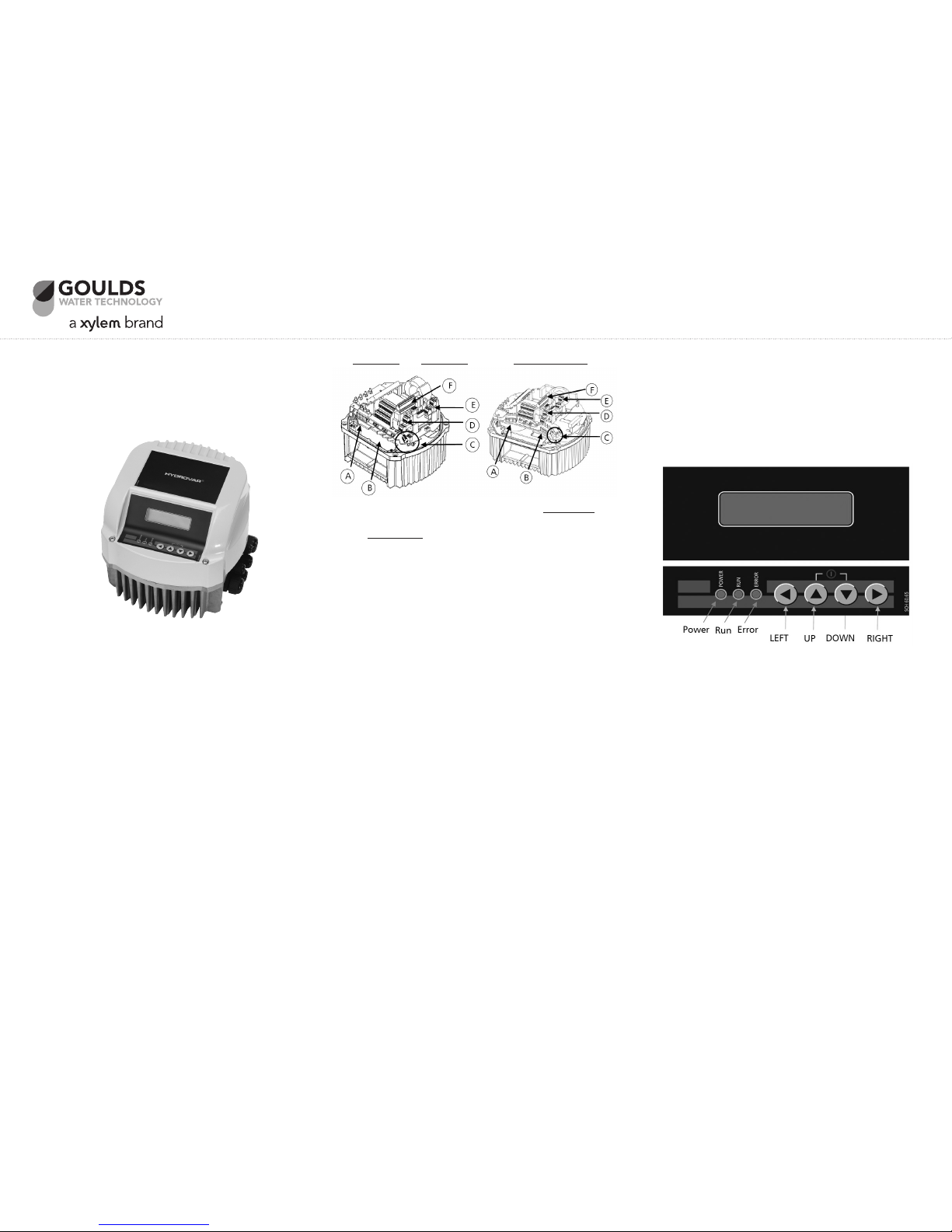
1 Ph 2, 3 HP 3 Ph 3, 5 HP 3 Ph 7.5, 10, 15 HP
(A) Power supply (B) Motor (C) Terminal block:
connections
- START/STOP
(D) RS-485 Interface (E) Status-Relays - SOLORUN
- User interface - RS-485 Interface
- Internal interface (F) Optional
Relay Card
4. Drive connection to motor: Route wires through
cable gland and other large conduit opening as
above. Connect wires to appropriate terminals. Use
crimp-on spades for sizes 2, 3, 5 HP. Terminate wires
at terminals U, V, W for sizes 7.5 HP and up.
*** Route the following low voltage wires
through small conduit glands and openings as
needed. ***
5. Attach transducer wires to terminals X3: 1-3; Shield,
White, Brown respectively.
6. Attach thermal overload switch to motor body at
conduit box screw, and terminate at the 2 terminals labeled X1 PTC. If not using Thermal overload
switch, place jumper between PTC terminals.
7. Provide Emergency stop switch, or jumper between
terminals X3: 7, 8.
8. Provide additional on/off switch or jumper between
terminals X3: 11, 12
9. If using multiple communicating drives, attach
RS485 wires to terminals X4: 4-6, (-, +, Shield respectively) on Master drives; X2: 1-3 on Basic drives.
Daisy chain communication wires starting at Master
drive to all additional drives.
10. Verify all connections are secure with no stray wires.
Attach ground wire from drive to cover and replace
cover. Note: Be sure cover sits securely on drive
without pinching any wires. Securely HAND TIGHTEN cover screws. Cover must be firmly attached for
buttons to function properly.
11. Connect power. The display should look as follows:
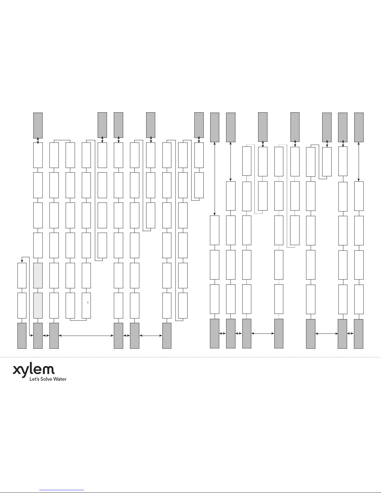
12. See attached flowchart for available programming
options to change.
13. Push Right arrow to next screen to change Setpoint.
Use Up/Down arrows to change setpoint, (Required
value).
14. Push left arrow once to get back to main screen.
Push left arrow again to get to Main menu. Use
Down arrow to scroll through menu options. To
change any parameter other than set point, you
must first enter a password. From main menu, scroll
down to Group 60, and push right arrow once to
parameter 61. Enter password using up arrow key,
(password = 66).
15. For multipump programming, change the highlighted parameters in the flowchart. Change: Parameter
105 to “Cascade Serial”; set the pump address to 1,
2, etc in parameter 106.
16. From main screen, press up arrow to start drive.
Check rotation on pump. Switch 2 of 3 line wires
from the drive at motor if reverse rotation.
XYLEM 0.0 Hz
STOP XXX.X PSI
QUICK START GUIDE
HYDROQSG
100 SUBMENU
BASIC SETTINGS
200 SUBMENU
CONF INVERTER
300 SUBMENU
REGULATION
400 SUBMENU
SENSOR
500 SUBMENU
SEQUENCE CNTR
100 SUBMENU
BASIC SETTINGS
60 SUBMENU
SETTINGS
200 SUBMENU
CONF INVERTER
300 SUBMENU
REGULATION
400 SUBMENU
SENSOR
500 SUBMENU
SEQUENCE CNTR
61 PASSWORD
0000
105 MODE
Controller
202 SOFTWARE
HV V01.3
205 MAX. UNITS
6
210 INVERTER
ALL
215 RAMP 1
4 sec
225 RAMP 3
70 sec
260 FMIN TIME
0 sec
265 BOOST
5 %
310 WINDOW
10 %
510 ACT.VAL.DEC
2 PSI
540 DROP FREQ
42.0 Hz
410 CONF SENSOR
Sensor 1
315 HYSTERESIS
80 %
515 ENABLE FREQ
48 Hz
545 OVERVALUE
disabled
415 SENSOR TYPE
analog I 4-20mA
320 REG. MODE
normal
520 ENABLE DLY
5 sec
550 OVERVAL DLY
0 sec
420 SENS. RANGE
300 PSI
325 FRQ. LIFT
30.0 Hz
525 SWITCH DLY
2 sec
555 SWITCH INTV
24 hours
425 SENS. CURVE
linear
330 LIFT AMOUNT
0.0 %
530 DISABLE FRQ
30.0 Hz
560 SYNCH.LIM.
0.0 Hz
565 SYNCH.WIN.
2 Hz
570 MSTPRIORITY
ON
430 SENS1 CAL 0
0 % = x,xx PSI
440 SENS2 CAL 0
0 % = x,xx PSI
435 SENS1 CAL X
0 % = xx,xx PSI
445 SENS2 CAL X
0 % = xx,xx PSI
285 SKIPFRQ CTR
0.0 Hz
270 KNEE FREQ.
60 Hz
286 SKIPFRQ RNG
60 Hz
275 POWER RED.
OFF
290 CURR. LIMIT
OFF
280 SEL.SW.FRQ.
Auto
291 CURR. LIMIT
100 %
230 RAMP 4
70 sec
235 RAMP FMIN A
2 sec
240 RAMP FMIN D
2 sec
245 MAX. FREQ
60 Hz
250 MIN. FREQ
20 Hz
220 RAMP 2
4 sec
203 SET VER INV
sel. 01 act. 01
106 PUMP ADDR
1
110 SET PASSW.
0066
115 LOCK FUNCT.
0066
120 DISP. CONTR.
75 %
125 DISP. BRIGHT
100 %
62 JOG Hz
50 PSI
305 JOG Hz
50 PSI
505 ACT.VAL.INC
5 PSI
535 DISABLE DLY
5 sec
405 DIMENS. UNIT
PSI
255 CONF. FMIN
F > 0
1000 SUBMENU
TESTRUN
800 SUBMENU
REQUIRED VALUES
700 SUBMENU
OUTPUTS
1000 SUBMENU
TESTRUN
1100 SUBMENU
SETUPS
1100 SUBMENU
SETUPS
605 MIN.THRESH.
disabled
705 ANALOG OUT1
Output frequency
1005 TESTRUN
100 hours
610 DELAY TIME
2 sec
1010 TESTRUN FREQ.
30 Hz
710 ANALOG OUT2
Actual value
810 C.REQ.VAL.2
OFF
1120 PASSWORD 2
0000
907 OFFS.INPUT
100
1210 BAUDRATE
9600
1215 FORMAT
RTU N81
830 ACTUAT.FRQ1
0.0 Hz
1220 PUMP ADDR
1
835 ACTUAT.FRQ2
0.0 Hz
805 C.REQ.VAL.1
digital
1110 FACTORY SET
USA
905 OFFS.INPUT
OFF
1205 ADDRESS
1
615 ERROR RESET
ON
1015 TESTR.BOOST
10 %
715 CONF REL 1
Running
815 SW REQ.VAL
Setpoint 1
1125 CLR ERRORS
ALL
910 LEVEL 1
0
915 LEVEL 2
100
1020 TESTR.TIME
5 sec
720 CONF REL 2
Errors
820 REQ.VAL.1
50 PSI
1130 CLR MOTORH.
ALL
912 OFFSET X1
0
917 OFFSET X2
100
1025 SEL.DEVICE
01
1030 TESTRUN MAN
Press > 3 sec
825 REQ.VAL.2
50 PSI
1135 CLR OPERAT.
Press > 3 sec
913 OFFSET Y1
0 PSI
918 OFFSET Y2
0 PSI
800 SUBMENU
REQUIRED VALUES
600 SUBMENU
ERRORS
600 SUBMENU
ERRORS
700 SUBMENU
OUTPUTS
1200 SUBMENU
RS485-INTERFACE
1200 SUBMENU
RS485-INTERFACE
900 SUBMENU
OFFSET
900 SUBMENU
OFFSET
Goulds is a registered trademark of Goulds Pumps, Inc. and is used under license.
© 2012 Xylem, Inc. HYDROQSG July 2009
Xylem, Inc.
2881 East Bayard Street Ext., Suite A, Seneca Falls, NY 13148
Phone: (800) 453-6777 • Fax: (888) 322-5877
www.xyleminc.com/brands/gouldswatertechnology
 Loading...