

Goulds Pumps HSC Installation, Operation And Maintenance Manual

INSTRUCTION MANUAL
IM008R04
Model HSC
INSTALLATION, OPERATION AND MAINTENANCE MANUAL

SUBJECT PAGE
Safety Instructions ........................................................................................................................................................ 3
Important ..................................................................................................................................................................... 3
Installation ................................................................................................................................................................... 3
Suction Piping .............................................................................................................................................................. 4
Discharge Piping........................................................................................................................................................... 4
Rotation ....................................................................................................................................................................... 4
Operation ..................................................................................................................................................................... 4
Maintenance................................................................................................................................................................. 4
Disassembly .................................................................................................................................................................. 4
Reassembly ................................................................................................................................................................... 5
Troubleshooting ........................................................................................................................................................... 5
Parts List ...................................................................................................................................................................... 6
Limited Warranty ......................................................................................................................................................... 7
Declaration of Conformity ......................................................................................................................................... 24
Pump Model Number:
Pump Serial Number:
Dealer:
Dealer Phone No.:
Date of Purchase:
Date of Installation:
Current Readings at Startup:
1 Ø 3 Ø L1-2 L2-3 L3-1
Amps: Amps:
Volts: Volts:
2
SAFETY INSTRUCTIONS
IMPMPMPMPMPMPMPMPMPMPMPORORTATATATATA
I
NSNSNSNS
NS
TATATATATATATA
NNNN
N
TO AVOID SERIOUS OR FATAL PERSONAL
INJURY OR MAJOR PROPERTY DAMAGE, READ
AND FOLLOW ALL SAFETY INSTRUCTIONS IN
MANUAL AND ON PUMP.
THIS MANUAL IS INTENDED TO ASSIST IN THE
INSTALLATION AND OPERATION OF THIS UNIT
AND MUST BE KEPT WITH THE PUMP.
This is a SAFETY ALERT SYMBOL.
When you see this symbol on the pump
or in the manual, look for one of the following signal words and be alert to the
potential for personal injury or property
damage.
DANGER
WARNING
CAUTION
NOTICE: INDICATES SPECIAL INSTRUCTIONS
THOROUGHLY REVIEW ALL INSTRUCTIONS
AND WARNINGS PRIOR TO PERFORMING ANY
WORK ON THIS PUMP.
MAINTAIN ALL SAFETY DECALS.
WARNING
Warns of hazards that WILL cause
serious personal injury, death or major
property damage.
Warns of hazards that CAN cause
serious personal injury, death or major
property damage.
Warns of hazards that CAN cause personal injury or property damage.
WHICH ARE VERY IMPORTANT AND
MUST BE FOLLOWED.
UNIT NOT DESIGNED FOR USE
WITH HAZARDOUS LIQUIDS OR
FLAMMABLE GASES. THESE
FLUIDS MAY BE PRESENT IN
CONTAINMENT AREAS.
1.3.
Motors must be wired for proper voltage. Motor
wiring diagram is on motor nameplate. Wire size
must limit maximum voltage drop to 10% of nameplate voltage at motor terminals, or motor life and
pump performance will be lowered.
1.4. Always use horsepower-rated switches, contactor and
starters.
1.5. Motor Protection
1.5.1. Single phase: Thermal protection for single
phase units is sometimes built in (check nameplate). If no built-in protection is provided, use
a contactor with a proper overload. Fusing is
permissible.
1.6 Maximum Operating Limits:
Liquid Temperature: 180$F (82$C)
Working Pressure: 125 PSI
Starts per Hour: 20, evenly distributed.
1.7 Regular inspection and maintenance will increase
service life. Base schedule on operating time.
2. INSTALLATION
2.1. Locate pump as near liquid source as possible (below
level of liquid for automatic operation).
2.2. Protect from freezing or flooding.
2.3. Allow adequate space for servicing and ventilation.
2.4. All piping must be supported independently of the
pump, and must “line-up” naturally.
CAUTION
DISCHARGE CONNECTIONS.
NEVER DRAW PIPING INTO PLACE BY
FORCING THE PUMP SUCTION AND
Hazardous fluids can
cause fire, burns
or death.
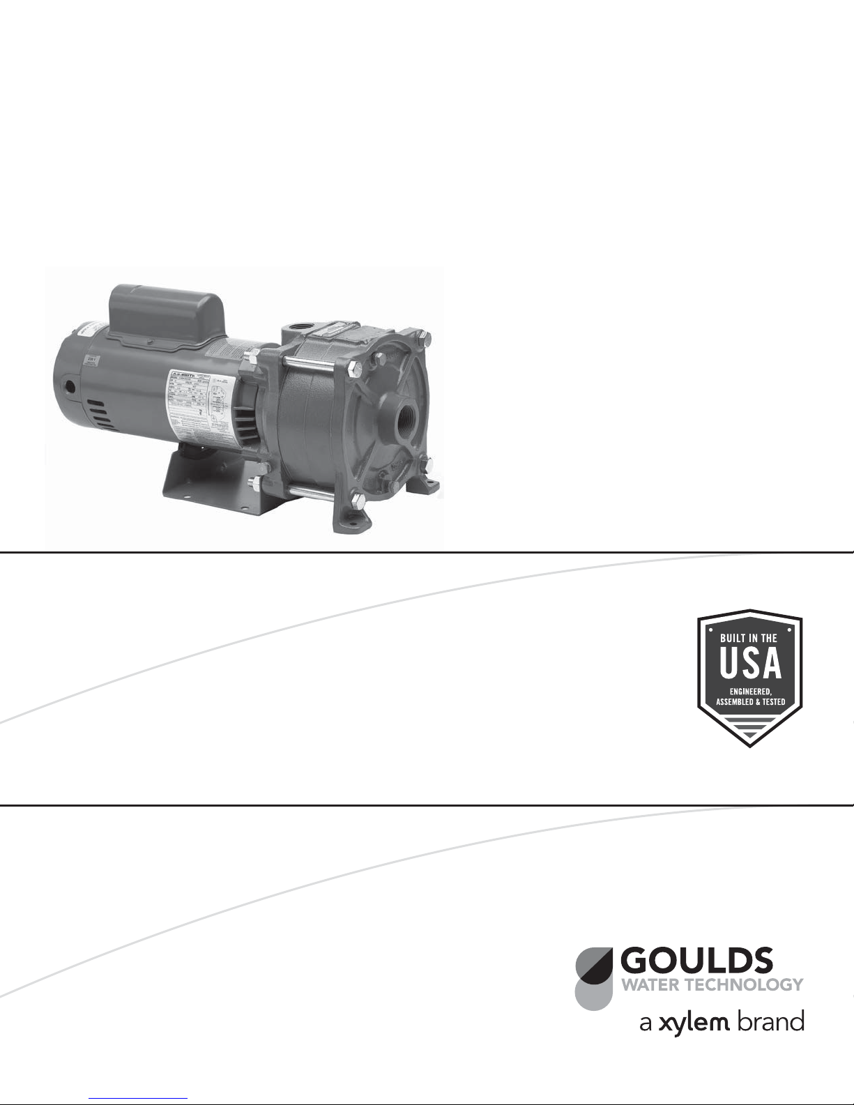
DESCRIPTION and SPECIFICATIONS:
The Model HSC is a multi-stage, end-suction, centrifugal
pump for general liquid transfer service, booster applications, etc. Liquid-end construction is cast iron, stainless
steel and engineered composites.
All units have NEMA 48 Frame single-phase, 115/230
V, 60 Hz motors with C-face mounting and NEMA 56J
threaded shaft extensions.
1. IMPORTANT
1.1. Inspect unit for damage. Report any damage to car-
rier/dealer immediately.
1.2. Electrical supply must be a separate branch circuit
with fuses or circuit breakers, wire sizes, etc., in
compliance with National and Local electrical codes.
Install an all-leg disconnect switch near pump.
CAUTION
CONTROLS.
ALWAYS DISCONNECT ELECTRICAL
POWER WHEN HANDLING PUMP OR
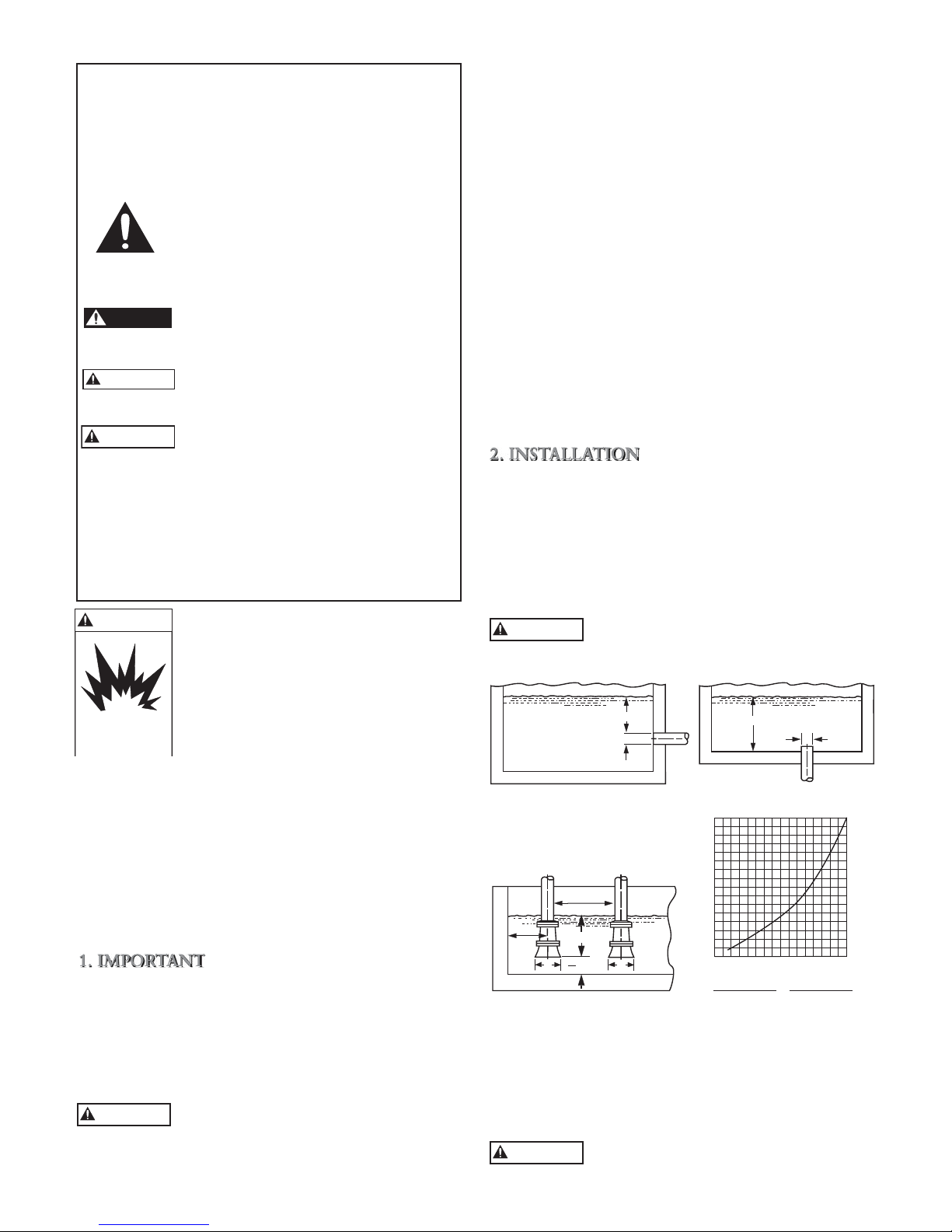
H min.
---------
D
---------
Figure 1
3.0D
min.
1.5D
min.
H min.
D
min.
D D
2
Figure 3 Figure 4
H min.
D
---------
---------
H
16
15
14
13
12
11
10
9
8
7
6
5
4
3
2
1
H = Min. Submergence in feet
1 2 3 4 5 6 7 8 9 10 11 12 13 14 15 16
V = Velocity in feet per second
=GPM x 0.321 GPM x 0.4085
Figure 2
Area D
2
2.5. Avoid unnecessary fittings. Select sizes to keep fric-
tion losses to a minimum.
2.6. Units may be installed horizontally, inclined or verti-
cally.
CAUTION
DO NOT INSTALL WITH MOTOR BELOW PUMP. ANY LEAKAGE OR CON-
DENSATION WILL AFFECT THE MOTOR.
V
3
2.7. Foundation must be flat and substantial to eliminate
UC
TITI
TI
ONONON
ON
IPIPIP
INGGG
ISISISISISISIS
ISISISARAR
GEGEGEGE
GE
GEGE
GEGEGEPIN
IN
INININ
INGGGG
OT
OT
AT
ATATATATAT
IOIOIOIOIONNN
N
O
PEPEPEPEPEPEPERARARARARARATITITTITITI
ONONON
ONON
ON
M
AI
AI
NTNTNTNTNTENENENENANAN
ANANANANANANAN
DASASASASASASAS
LY
strain when tightening bolts. Use rubber mounts to
minimize noise and vibration.
2.8. Tighten casing hold-down bolts before connecting
piping to pump.
2.9. No field alignment of pump to motor is necessary as
pumps are close-coupled.
3. SUCTION PIPING
3.1. Low static suction lift and short, direct suction piping
is desired. Consult pump performance curve for
Net Positive Suction Head Required (NPSHR), espe-
cially for lifts above 15'.
3.2. Suction pipe must be at least as large as the suction
connection of the pump. Smaller size will degrade
performance.
3.3. If larger pipe is required, an eccentric pipe reducer
(with straight side up) must be installed at the pump.
3.4. Installation with pump below source of supply:
3.4.1. Install full flow isolation valve in piping for
inspection and maintenance.
CAUTION
3.5. Installation with pump above source of supply:
3.5.1. Avoid air pockets. No part of piping should be
3.5.2. All joints must be airtight.
3.5.3. Foot valve to be used only if necessary for
3.5.4. Suction strainer open area must be at least
3.6. Size of inlet from liquid source, and minimum
submergence over inlet, must be sufficient to prevent
air entering pump through vortexing. See Figures 1
through 4.
3.7. Use 3 to 4 wraps of Teflon tape to seal threaded con-
nections.
DO NOT USE SUCTION ISOLATION
VALVE TO THROTTLE PUMP.
higher than pump suction connection. Slope
piping upward from liquid source.
priming, or to hold prime on intermittent
service.
triple the pipe area.
4. DISCHARGE PIPING
4.1. Arrangement must include a check valve located
between a gate valve and the pump. The gate valve
is for regulation of capacity, or for inspection of the
pump or check valve.
4.2. If an increaser is required, place between check valve
and pump.
4.3. Use 3 to 4 wraps of Teflon tape to seal threaded con-
nections.
5. ROTATION
5.1. Correct rotation is right-hand (clockwise when
viewed from the motor end). Switch power on and
off quickly. Observe shaft rotation.
4
5.1.1. Single-phase motor: Non-reversible
5.1.2. Three-phase motor: Not offered.
6. OPERATION
6.1. Before starting, pump must be primed (free of air
and suction pipe full of liquid) and discharge valve
partially open. Plugs are provided in the casing and
valve so pump/suction piping can be filled and/or
vented/drained in any pump orientation.
6.2. Make complete check after unit is run under operat-
ing conditions and temperature has stabilized. Check
for expansion of piping.
7. MAINTENANCE
7.1. Ball bearings are located in and are part of the mo-
tor. They are permanently lubricated. No greasing
required.
CAUTION
ING PARTS WILL SEIZE AND MECHANICAL SEAL
WILL BE DAMAGED. DO NOT OPERATE AT OR
NEAR ZERO FLOW. ENERGY IMPARTED TO THE
LIQUID IS CONVERTED INTO HEAT. LIQUID MAY
FLASH TO VAPOR. ROTATING PARTS REQUIRE
LIQUID TO PREVENT SCORING OR SEIZING.
PUMPED LIQUID PROVIDES LUBRICATION. IF PUMP IS RUN DRY, ROTAT-
8. DISASSEMBLY
Complete disassembly of the unit will be described. Proceed only as far as required to perform the maintenance
work required.
8.1. Turn off power.
8.2. Drain system and flush if necessary.
8.3. Disassembly of Liquid-End:
8.3.1. Remove casing bolts.
8.3.2. Remove motor and remaining Liquid-End as-
sembly from casing (still connected to piping)
and position vertically for easier disassembly.
8.3.3. Remove impeller bolt and washer.
CAUTION
PREVENT ROTATION OF CLOSE-COUPLED UNITS.
REMOVE CAP AT OPPOSITE END OF MOTOR. A
SCREWDRIVER SLOT OR A PAIR OF FLATS WILL BE
EXPOSED. USING THEM WILL PREVENT IMPELLER
DAMAGE.
8.3.4. Remove impeller by pulling axially.
8.3.5. Remove separator plate.
8.3.6. Remove shaft sleeve.
8.3.7. Remove intermediate stage.
8.3.8. Repeat steps 8.3.4 through 8.3.7 for three
8.3.9. Remove last impeller.
8.3.10. Remove last separator plate.
DO NOT INSERT SCREWDRIVER
BETWEEN IMPELLER VANES TO
stage pumps.

8.3.11. Remove seal retainer.
EAEAEAEABLBLBLBLBLBLY
Y
.TRBLBLBLBLBL
ESESESESESHOHOHOHOHOHOHOHOG G G
ARAR
ARAR
ARARARAR
ARARTTTTTTT
T
T
8.3.12. Remove shaft extension using a screwdriver in
the slot or flats in the back of the motor to prevent rotation and a wrench to turn extension.
8.3.13. Pry off the rotating element of the mechani-
cal seal from the motor shaft by using two (2)
regular screw drivers 180º apart and using the
motor adapter inner boss as a fulcrum point
and then prying seal up.
8.3.14. Remove the motor adapter bolts, washers and
o-rings.
8.3.15. Remove the motor adapter.
8.3.16. Remove the stationary element of the mechani-
cal seal by pushing it out from the motor side
with a blunt instrument.
9. REASSEMBLY
9.1. All parts should be cleaned before assembly.
9.2. Refer to parts list to identify required replacement
items. Specify pump index or catalog number when
ordering parts.
9.3. Reassembly is the reverse of disassembly.
9.4. Observe the following when reassembling the liquid-
end:
9.4.1. All mechanical seal components must be in
good condition or leakage may result. Replacement of complete seal assembly, whenever seal
has been removed, is good standard practice.
It is permissible to use a light lubricant, such as
glycerin, to facilitate assembly. Do not contaminate the mechanical seal faces with lubricant.
9.4.2. Inspect the o-rings and replace if damaged.
The o-rings may be lubricated with petroleum
jelly to ease assembly.
9.4.3. Inspect impellers for wear, degradation or
blockage. Clean or replace as necessary.
9.4.4. Inspect iron parts for excessive corrosion or
degradation. Replace as necessary.
9.4.5. Inspect stainless steel components for excessive
wear or degradation and replace as necessary.
9.4.6. Wear rings contained in the interstage(s) and
casing would need to be pressed or pried out
and pressed in should they need replacement.
9.5. Check reassembled unit for binding and correct as
necessary.
9.6. Be sure to tighten casing bolts in a criss-cross manner
to prevent o-ring binding and cracking of the casing
ears. Secure to 35 ft-lbs.
10. TROUBLESHOOTING CHART
MOTOR NOT RUNNING
(See causes 1 through 6)
LITTLE OR NO LIQUID DELIVERED
(See causes 7 through 16)
POWER CONSUMPTION TOO HIGH
(See causes 4, 16, 17, 18, 21)
EXCESSIVE NOISE AND VIBRATION
(See causes 4, 6, 9, 12, 14, 15, 17, 19, 20, 21)
PROBABLE CAUSE
1. Tripped thermal protector
2. Open circuit breaker
3. Blown fuse
4. Rotating parts binding
5. Motor wired improperly
6. Defective motor
7. Not primed
8. Discharge plugged or valve closed
9. Incorrect rotation
10. Foot valve too small, suction not submerged,
inlet screen plugged.
11. Low voltage
12. Air or gasses in liquid
13. System head too high
14. NPSHA too low: Suction lift too high or suction
losses excessive. Check with vacuum gauge.
15. Impeller worn or plugged
16. Incorrect impeller diameter
17. Head too low, causing excessive flow rate
18. Viscosity or specific gravity too high
19. Worn bearings
20. Pump or piping loose
21. Pump and motor misaligned
5
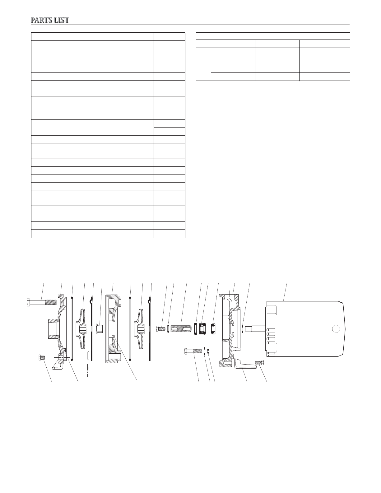
PARTS LIST
LI
Item Part Name Quantity
1 Pipe Plug ¼" NPT 3
2 Bolt – casing to adapter, 2 stage 4
2 Bolt – casing to adapter, 3 stage 4
3 Casing 1
4 O-Ring – casing and intermediate stage 1 per stage
5 Impeller – ¾, 1 and 1½ HP 2
Impeller – 2 HP 3
6 Coverplate (1 per impeller)
7 Sleeve
(2 – 3 stage)
8 Intermediate Stage
(2 – 3 stage)
9 Impeller Bolt 1
9, 10,
11, 12
10 Washer – impeller (1) and adapter (4) 5
12 Seal Retainer 1
13, 14 Shaft Seal Assembly 1
15 Motor Adapter 1
16 Bolt – adapter to motor 4
17 O-Ring – motor adapter bolts 4
18 Foot 1
19 Bolt – foot to adapter 1
21 Wear Ring 1 per impeller
22 (eŷector 1
(1 – 2 stage)
(1 – 2 stage)
Shaft Extension Assembly 1
Motor Codes
Item HP Model Order No.
¾ HSC07 J05853
1 HSC10 J06853
20
1½ HSC15 J07858
2 HSC20 J08854
2891011121314152220
34 567
1211610171819
21
456
6

COMMERCIAL WARRANTY
For goods sold to commercial buyers, Seller warrants the goods sold to Buyer hereunder (with the exception of membranes, seals, gaskets,
elastomer materials, coatings and other “wear parts” or consumables all of which are not warranted except as otherwise provided in the quotation or
sales form will be (i be built in accordance with the speciŶcations referred to in the quotation or sales form, if such speciŶcations are expressly made
a part of this Agreement, and (ii) free from defects in material and workmanship for a period of one (1) year from the date of installation or twelve
(12) months from the date of shipment (which date of shipment shall not be greater than eighteen (18) months after receipt of notice that the goods
are ready to ship), whichever shall occur Ŷrst, unless a longer period is speciŶed in the product documentation (the “;arranty”).
Except as otherwise required by law, Seller shall, at its option and at no cost to Buyer, either repair or replace any product which fails to conform
with the ;arranty provided Buyer gives written notice to Seller of any defects in material or workmanship within ten (10) days of the date when any
defects or nonconformance are Ŷrst manifest. 9nder either repair or replacement option, Seller shall not be obligated to remove or pay for the
removal of the defective product or install or pay for the installation of the replaced or repaired product and Buyer shall be responsible for all other
costs, including, but not limited to, service costs, shipping fees and expenses. Seller shall have sole discretion as to the method or means of repair
or replacement. BuyerŒs failure to comply with SellerŒs repair or replacement directions shall terminate SellerŒs obligations under this ;arranty and
render the ;arranty void. Any parts repaired or replaced under the ;arranty are warranted only for the balance of the warranty period on the parts
that were repaired or replaced. Seller shall have no warranty obligations to Buyer with respect to any product or parts of a product that have been:
(a) repaired by third parties other than Seller or without Seller’s written approval; (b) subject to misuse, misapplication, neglect, alteration, accident,
or physical damage; (c) used in a manner contrary to Seller’s instructions for installation, operation and maintenance; (d) damaged from ordinary
wear and tear, corrosion, or chemical attack; (e) damaged due to abnormal conditions, vibration, failure to properly prime, or operation without ŷow;
(f) damaged due to a defective power supply or improper electrical protection; or (g) damaged resulting from the use of accessory equipment not
sold or approved by Seller. In any case of products not manufactured by Seller, there is no warranty from Seller; however, Seller will extend to Buyer
any warranty received from Seller’s supplier of such products.
8,E FOREGOING ;ARRAN8Y IS EX'09SI:E AN( IN 0IE9 OF ANY AN( A00 O8,ER EXPRESS OR IMP0IE( ;ARRAN8IES, G9
'ON(I8IONS OR 8ERMS OF ;,A8E:ER NA89RE RE0A8ING 8O 8,E GOO(S PRO:I(E( ,ERE9N(ER, IN'09(ING ;I8,O98 0IMI8A8ION ANY
IMP0IE( ;ARRAN8IES OF MER',AN8ABI0I8Y AN( FI8NESS FOR A PAR8I'90AR P9RPOSE, ;,I', ARE ,EREBY EXPRESS0Y (IS'0AIME( AN(
EX'09(E
ANY OF 8,E FOREGOING ;ARRAN8IES ARE 0IMI8E( 8O REPAIRING OR REP0A'ING 8,E PRO(9'8 AN( S,A00 IN A00 'ASES BE 0IMI8E(
8O 8,E AMO9N8 PAI( BY 8,E B9YER FOR 8,E (EFE'8I:E PRO(9'8. IN NO E:EN8 S,A00 SE00ER BE 0IAB0E FOR ANY O8,ER FORM OF
(AMAGES, ;,E8,ER (IRE'8, IN(IRE'8, 0I59I(A8E(, IN'I(EN8A0, 'ONSE59EN8IA0, P9NI8I:E, EXEMP0ARY OR SPE'IA0 (AMAGES,
IN'09(ING B98 NO8 0IMI8E( 8O 0OSS OF PROFI8, 0OSS OF AN8I'IPA8E( SA:INGS OR RE:EN9E, 0OSS OF IN'OME, 0OSS OF B9SINESS, 0OSS
OF PRO(9'8ION, 0OSS OF OPPOR89NI8Y OR 0OSS OF REP98A8ION.
(. EX'EP8 AS O8,ER;ISE RE59IRE( BY 0A;, B9YER’S EX'09SI:E REME(Y AN( SE00ER’S AGGREGA8E 0IABI0I8Y FOR BREA', OF
ARAN8EES,
Xylem Inc.
2881 East Bayard Street Ext., Suite A
Seneca Falls, NY 13148
Phone: (800) 453-6777
Fax: (888) 322-5877
www.gouldswatertechnology.com
Goulds is a registered trademark of Goulds Pumps, Inc. and is used under license.
© 2015 Xylem Inc. IM008 Revision 4 October 2015
7
MANUAL DE INSTRUCCIÓN
IM008R04
Modelo HSC
INSTRUCCIONES DE INSTALACIÓN, FUNCIONAMIENTO Y MANTENIMIENTO
8
 Loading...