

Page 1

Installation, Operation and Maintenance Instructions
Page 2

TABLE OF CONTENTS
1.0 Introduction …………………………………………………………………… 2
2.0 Safety Considerations….…………………………………………………… 2
3.0 General Overview……………………………………………………………. 2
3.1 Warranty Statement……………….………………………………… 2
3.2 Application……………………….…………………………………… 2
3.3 Storage / Handling……………….………………………………….. 3
4.0 Installation…………………………………………………………………………………..… 4
4.1 General Description………………………………………………………………… 4
4.2 Motor Mounting System……………………………………………………………. 5
4.3 Foundation Mounted Baseplates …………………………………………..……. 5
4.4 Stilt Mounted Baseplates ………………………… ………………………………. 7
Appendix I. Corrosion Guide
Appendix II. Insert Installation Guide
Appendix III Recommended Fastener Torques
Appendix IV Alignment
Questions?
Please contact your local Goulds Pumps represent ati ve.
ChemBasePlus™ 02/15/02— 1/2002 Page 1 of 16
Page 3

SECTION 1. 0 INTRODUCTION
This Installation, Operation, and Maintenance
Instructions manual contains instructions and
guidelines for the installation of the Goulds
Pumps ChemBasePlus™ baseplate.
SECTION 2.0 – SAFETY CONSIDERATIONS
The Goulds ChemBasePlus™ baseplate has
been designed and packaged for safe handling
and installation. It is very important to review
the contents of this manual before removing
the baseplate from its shipping skid. Goulds
shall not be liable for physical injury, damage
caused by failure to observe the instructions
for installation and handling in this manual.
Please make special note of the following
general precautions as listed below:
1. Do not remove the ChemBasePlus™
from its shipping skid until you are
ready to lift it onto its foundation.
2. Do not subject the ChemBasePlus™
to rough handling or unnecessary
hammer shock.
3. Do not attempt to lift the
ChemBasePlus™ by any means other
than that which is described in this
manual.
It is extre me ly importa nt that th is entire
guideline be reviewed prior to installation
and handling of the baseplate. This is
important for both safety and reliability
purposes.
4. Do not hammer shock or use other
impact loading techniques to adjust
the positioning of the
ChemBasePlus™. Do not pry against
the motor mounting blocks when
moving the motor during shaft
alignment.
5. Do not tighten the anchor bolt nuts
until you have verified that the
ChemBasePlus™ is properly
supported.
6. Do not attempt to transport, handle or
install a ChemBasePlus™ when
ambient temperature is below -45° F.
7. Do not operate a pump installed on a
ChemBasePlus™ at process fluid
temperatures in excess of 290° F.
SECTION 3.0 - GENERAL OVERVIEW
3.1 WARRANTY STATEMENT
All due care is taken in producing the Goulds
line of baseplates and complimentary
accessory items. Goulds warrants to provide
equipment that meet Goulds’ standards and
specifications, but not to be suitable for any
particular application. No warranty is made in
regard to the use of the materials or finished
goods, in the Purchaser’s application. All
design co nsiderations and acce ptance of the
Goulds products for use in the Purchaser’s
applications are the Purchaser’s sole
responsibility. In no case will Goulds be
responsible for more than supplying
replacement products.
ChemBasePlus™ — 1/2002 Page 2 of 16
3.2 APPLICATION
The polymer composite material used in the
manufacture of the Goulds ChemBasePlus™
has been formulated for application in a broad
range of corrosive fluid handling services. This
material does not, however, offer universal
corrosion resistance. Goulds highly
recommends that the Corrosion Guide in
Appendix I be reviewed prior to specifying or
installing a ChemBasePlus™ baseplate.
The ChemBa sePlus™ is also suitable for
application in a wide range of fluid process
temperatures, specifically, -45° F to 290° F.
For temperature boundaries exceeding these
recommended limitations, please contact
Goulds for assistance in determining
acceptability of a specific application.
Page 4

3.3 STORAGE / HANDLING
Goulds’ normal packaging is designed to
protect the ChemBasePlus™ during shipment.
for safe, even lifting. Raise the
ChemBasePlus™ slightly off the pallet and
verify that it suspends reasonably level and
that the slings are not subject to slipping out of
! CAUTION !
position.
It is extremely important to observe proper
handling procedures during transport and
installation of the ChemBasePlus™. While the
polymer composite material is constructed of
inherently high strength materials, subjecting it
Be sure to keep hands and feet out from under
the baseplate during these steps to prevent
injury.
! WARNING !
to impact or bending loads through rough
handling or improper lifting or mounting may
result in irreparable damage to the baseplate
as well as potential damage to the mounted
equipment or put personnel at risk of injury
Leave the ChemBasePlus™ strapped to its
wooden shipping pallet until installation is
ready to occur. If the ChemBasePlus™ is
intended for indoor installation and comes with
carbon steel inserts, but is to be stored in an
outdoor location, cover the base completely
with some weather resistant material so as to
prevent rusting of the insert material.
! WARNING !
Do not stand the ChemBasePlus™ on end to
make more efficient use of storage space.
Severe personal injury or death as well as
possible permanent damage to the
ChemBasePlus™ may result should it tip over.
LIFTING
Lifting should be performed by trained
personnel only. Pumps and motors typically
have integral lifting eye bolts. These are
intended for use of the individual units only.
Do not use these features to lift a
ChemBasePlus™/ Pump and Motor Assembly.
ChemBasePLUS™ with no mounted equipment
Should the slinging appear unstable, set the
baseplate back down on the pallet and
reposition the slings for more stable condition.
After satisfactory slinging has been achieved,
the baseplate may be hoisted onto its
foundation. Slowly lower the baseplate over
the foundation using care to engage the
anchor bolts in the holes provided. Place
shims or wedges under the baseplate at a
minimum of four locations to allow for removal
of the slings
.
FIGURE 1
ChemBasePlus™
Baseplates With No Mounted Equipment
ChemBasePlus™
Baseplates With Installed Equipment:
! WARNING !
Do not install eye bolts in the
ChemBasePlus™ threaded inserts for the
purpose of lifting the baseplate. This practice
may induce excessive loading on the inserts,
which they were not designed to withstand.
Pump only installed:
Remove the straps that hold the
ChemBasePlus™ to the wooden pallet. Install
a sling around the pump suction nozzle using a
choker hitch pulled firmly tight. Install an
additional sling around the motor end of the
Remove th e s traps tha t s e c u r e th e
ChemBasePlus™ to the wooden pallet. Slip
ChemBasePlus™ using a basket hitch as
shown in Figure 2.
two slings underneath the baseplate between
the pallet cross members as shown in
Figure 1. Slings should be positioned to allow
ChemBasePlus™ — 1/2002 Page 3 of 16
Page 5
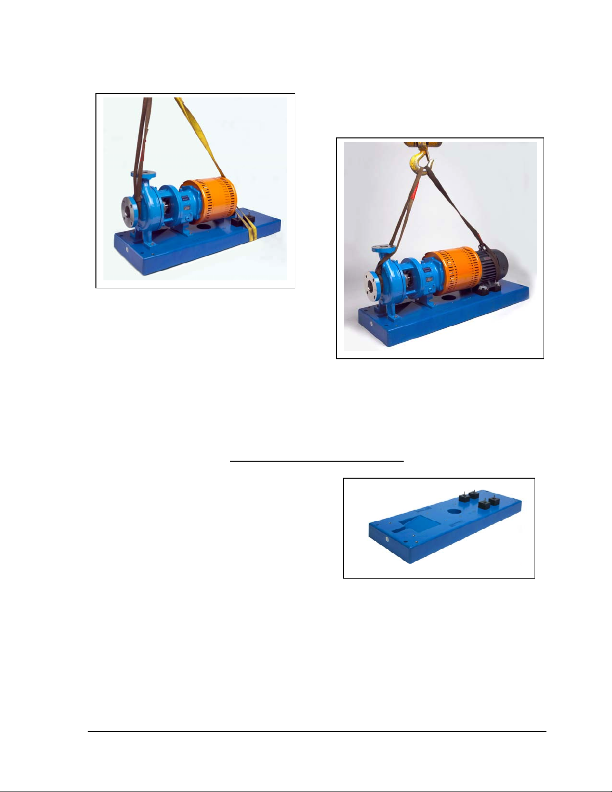
FIGURE 2 - Pump only Installed
Pump and mo tor installed:
Remove the straps that hold the
ChemBasePlus™ to the wooden pallet. Install
a sling around the pump suction nozzle and
around the outboard end of the motor frame
using choker hitches pulled firmly
tight as shown in Figure 3. The motor sling
should be positioned so the weight is not
carried through the motor fan housing.
FIGURE 3 - Pump and motor installed
SECTION 4.0 – INSTALLATION
4.1 GENERAL DESCRIPTION OF THE
ChemBasePlus™
The Goulds ChemBasePlus™ is a solid
polymer composite baseplate that is
manufactured to conform to ASME/ANSI
B73.1M-1991 and custom versions. The
Goulds ChemBasePlus™ has been designed
to provide a solid and rigid foundation under
the pump and its respective motor, whereby,
serving the purpose of maintaining sound
alignment between them.
The ChemBa sePlus™ has been made
available in two basic types:
• Foundation mounted (grouted in
design – Figure 4)
ChemBasePlus™ — 1/2002 Page 4 of 16
FIGURE 4 – Foundation Mounted
Page 6
• Stilt Mounted (free standing –
Figure 5)
FIGURE 5 – Stilt Mounted
The foundation -mounted style utilizes grout to
add rigidity to the structure. Because the
ChemBasePlus™ by nature offers excellent
rigidity, the Stilt-mounted style can be
employed without sacrificing on reliability
whatsoever. The Stilt-mounted base offers a
free-standing rigid foundation void of any
additional grouting needs.
Resin Aggregate Material utilized in
the construction of these baseplates.
3) To allow the end user to perform final
field alignment to their respective
tolerance standards.
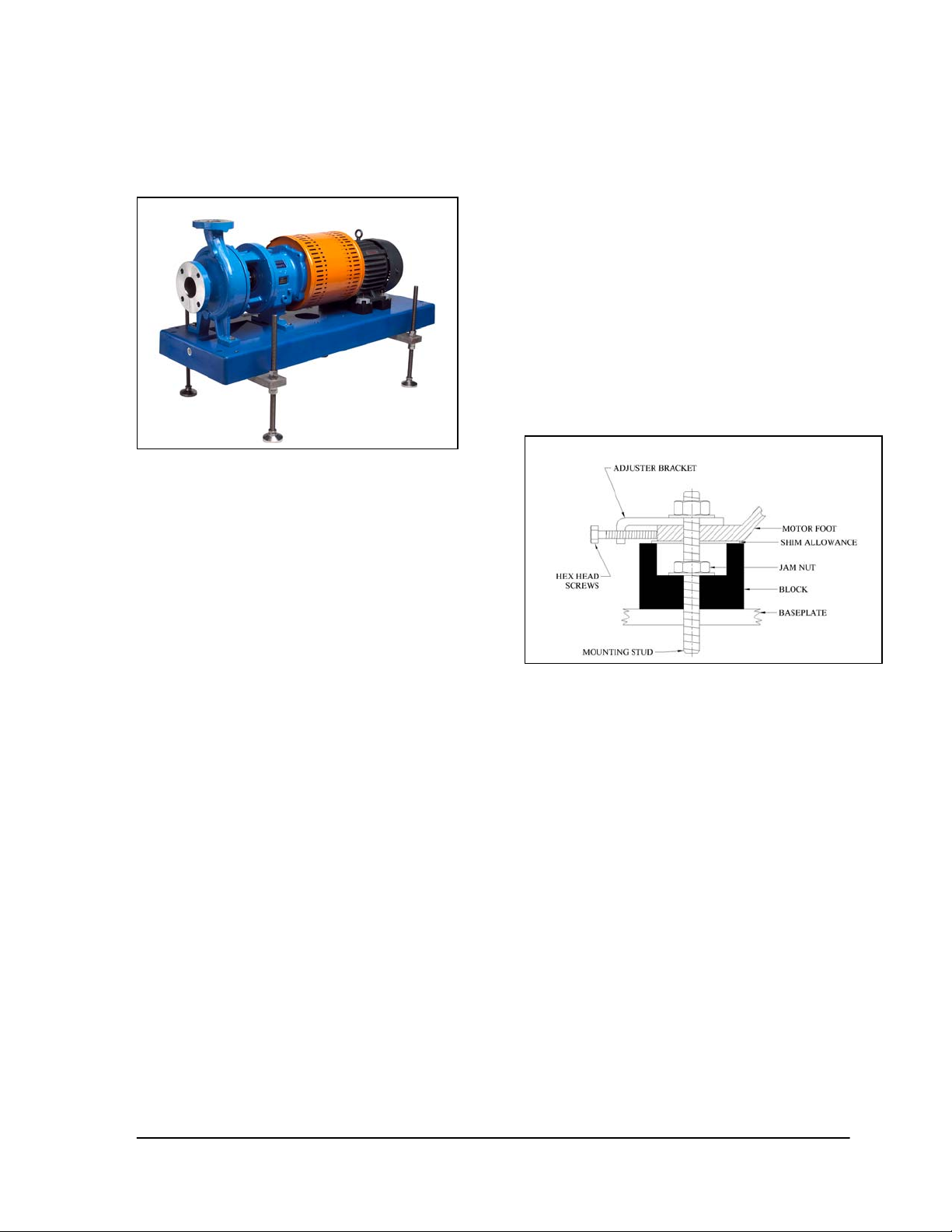
4.2 MOTOR MOUNTING SYSTEM
The Goulds ChemBasePlus™ utilizes as
standard the polymer block mounting system.
This system is comprised of corrosion resistant
polymer composite mounting blocks which
have surface flatness to .005”. Motor mounting
blocks incorporate a counterbore / jam nut
feature fo r s e c ure atta chment to th e
ChemBasePlus™
The ChemBa sePlus™ performs the proper
function of a reliable baseplate foundation for a
pump and motor. Those basic functions are as
follows:
1) To provide adequate rigidity to assure
the pump/motor assembly can be
shipped and installed without damage
and to withstand the operating loads of
the given assembly. The solid
structure of the ChemBasePlus™
offers superior dampening to vibration
associated with the rotating
pump/motor assembly.
2) To provide a flat mounting surface for
the pump and motor assembly. The
ChemBasePlus™ product is designed
to hold under a .005 inch flatness
specification (end-to-end). The
aforementioned flatness specifications
are measured across the diagonal
corners of the ba seplate to p surface.
These excellent flatness specifications
are achieved by the superior Epoxy
FIGURE 6
Optional Bi-Directional motor adjusters provide
both axial and transverse motor adjustment.
The top mounted adjusters assist with precise
shaft alignment when critical tolerances are
trying to be achieved as they do not disturb
indicator equipment.
4.3 FOUNDATON MOUNTED BASEPLATES
1) The baseplate should be positioned as
close to the liquid supply source as
possible. There should be an
adequate amount of space for
personnel to install, operate and
maintain the pump/motor assembly.
As mentioned above, the end result of
the grouted in baseplate should offer
excellent rigidity and dampen any
vibration associated with the operating
pump/motor assembly.
ChemBasePlus™ — 1/2002 Page 5 of 16
Page 7

2) Using the recommended slinging
procedures shown in Figures 2 and 3,
hoist the ChemBasePlus™ unit off its
shipping pallet.
6) Install the flat washers and nuts to the
anchor bolts and snug them down but
do not torque them at this point.
3) Lower the ChemBasePlus™ into
position over the foundation. Proceed
to engage the anchor bolts in the four
holes provided. As seen in Figure 7,
protective sleeves should be placed
over the anchor b olts to prevent grout
adhesion to the bolts.
FIGURE 7
4) The baseplate assembly should be
properly leveled. It is suggested to
utilize the pump suction and discharge
flanges as reference points for leveling
purposes. If the ChemBasePlus™ is
equipped with the recommended
optional leveling screw inserts, install
the leveling screws and thread them
far enough to provide the desired
grouting clearance underneath. Apply
wax to screws to allow for their
eventual removal.
5) If the ChemBasePlus™ is not
equipped with leveling screws, shim
under the baseplate to bring the
discharge flange into proper level.
Never stress the baseplate under any
condition to bring the assembly into
the desire d level. Hold off bo lting the
pump’s flanges until the baseplate is
completely installed. A proper
practice is to shim under all baseplate
anchor bolt locations. Apply wax to
shims to allow for their eventual
removal.
7) Alignment should now be done in
accordance with procedures identified
in Appendix IV.
8) The baseplate should now be properly
grouted. Grout the baseplate in
accordance with the grout
manufacturer’s recommended
procedures. Mask off areas not
intended to be grouted. Good
procedure is to utilize a non-shrinking
grout material. Pour or trowel the
grout into the desired area until the
proper level is reached. Immediately
wipe away any spills as this must be
done before the grout sets. Allow at
least two days for the grout to fully
cure.
9) Check for voids after the grout has
properly cured. Remove the forms
and withdraw the leveling screws or
shims used for leveling. Remove the
masking from all surfaces.
10) Fill the leveling screw holes (if
provided) with a flexible sealer.
11) Lubricate the anchor bolt threads and
tighten the nuts to the following torque
values: ½” bolt – 22 lb/ft or ¾” – 65
lb/ft.
12) Connect piping to the flanges of the
pump. Assure that no adv erse pipin g
loads are transmitted to the pump
flanges. Perform a final alignment
check for verification that there are no
significant piping loads.
13) Final alignment of the pump/motor
assembly should now be brought into
the tolerances as specified in
Appendix IV.
14) It is possible that a realignment may
be deemed necessary should the
temperature of the process conditions
cause suspect thermal expansion of
the piping.
ChemBasePlus™ — 1/2002 Page 6 of 16
Page 8

4.4 STILT MOUNTED BASEPLATES
As mentioned previously, the
ChemBasePlus™ is inherently rigid due to its
thickness of construction. The end result is a
baseplate that can be stilt mounted while not
sacrificing on reliability. The pump/motor
alignment techniques for Goulds’ Stilt Mounted
baseplates follow the same methodology of the
grouted in baseplates. The key difference
revolves around the way the baseplate is
leveled.
1) The stilt mounted baseplate is set on a
flat surface with no anchor bolts
needed.
2) The baseplate is leveled by using the
nut stilt adjuster kit. Refer to
Figures 8 and 9 for suggested
asse mbly instructions.
a) Elevate the baseplate assembly
above the floor to allow stilt
assembly.
b) Measure the approximate desired
height of the baseplate assembly
above the foundation.
c) Locate the bottom nuts above the
stilt threaded bolts to desired
height.
d) Insert the lock washer over the stilt
bolt.
e) Move the threaded stilt bolt up
through the holes in the bottom of
the baseplate and secure in place.
f) Attach the remaining lock washer
and nuts on to the threaded stilt
bolt. Fasten the nut on to the lock
washer.
g) Secure all four threaded stilts.
Now locate the baseplate
assembly over the flexible leveling
feet and tighten the feet to the
threaded stilts. Now lower the
entire assembly to the foundation.
h) Make final level and height
adjustments by simply loosening
the top nuts and turning the bottom
nuts to raise or lower the
baseplate assembly.
i) Finally, first tighten the top and
bottom nuts located on the
respective lock washers and then
tighten the other nuts to insure the
baseplate is properly locked in
place.
FIGURE 8
At this point, follow the steps as listed above
(Steps 12, 13, and 14) for grouted baseplates.
FIGURE 9
ChemBasePlus™ 02/15/02— 1/2002 Page 7 of 16
Page 9

APPENDIX I
Corrosion Guide
ChemBasePlus™ — 1/2002 Page 8 of 16
Page 10

Corrosion Guide, con’t.
ChemBasePlus™ — 1/2002 Page 9 of 16
Page 11

Corrosion Guide, con’t.
ChemBasePlus™ — 1/2002 Page 10 of 16
Page 12

APPENDIX II
Insert Guide
The following guide is to assist with the field
installation of inserts if there is a need to
replace a damaged thread or to install a new
insert into a custom location. In order to
achieve a successful installation the following
procedures are recommended:
! WARNING !
Field installation should only be performed by
qualified personnel using suitable drilling
equipment. Personnel should be sure to use a
face mask to prevent inhalation of silica dust
as the ChemBasePlus™ casting is penetrated
during drilling operations. If MSDS
specifications are required, contact your local
Goulds representative. Also, be sure to utilize
protective eyewear while performing any
drilling operation.
1. It is recommended to utilize a carbide tip
drill bit to perform drilling procedure.
Please refer to Table 1 for drill bit size
recommendation. We suggest providing
a hole diameter that will allow ample
space to install the insert yet still maintain
a snug fit as to not need too much filler
epoxy resin.
3. Drill the new hole (Figure 1) or drill ou t
the damaged insert taking care not to
enlarge or elongate the hole into which
the new insert will be installed. Remove
all dust and metal particles from the
drilled hole using compressed air.
FIGURE 1
Table 1
Hole Drill Size Recommendation
Insert Size Drill Size*
1 / 4 – 20 0.625 in.
5 / 16 – 18 0.625 in.
3 / 8 – 16 0.875 in.
1 / 2 – 13 1.000 in.
5 / 8 - 11 1.375 in.
*NOTE: Drill size list ed abov e is mi n imum —
increasing the hole diameter by an extra 0.125
inches may assist in allowing for any hole
location variances established by installer.
2. Drill approximately 1/8” (.125) lower then
the given length of the provided insert.
4. It is critical that perpendicularity in relation
to the surface of the ChemBas ePlus™ is
maintained. Goulds prescribes two basic
methods of insuring that the insert will
achieve proper perpendicularity and are as
follows:
a) Fabricate a template (i.e. constructed of
plywood or metal) based off the number
of inserts. The template should be
designed to locate the holes off a
reference point located on the respective
drawing of the given baseplate (please
contact your Goulds Pumps
representative if you are in need of a
particular drawing or consult factory).
Fasten the insert to a stud with a nut on
the top side of the template
ChemBasePlus™ — 1/2002 Page 11 of 16
Page 13

(Figure 2). Prior to placing the template /
insert assembly down on the baseplate as
seen in Figure 2, proceed to step 5 for
filling the hole with the proper amount of
epoxy resin.
FIGURE 2
b). With the pump assembly elevated above
the baseplate, fasten the insert to the
bottom of the motor hex bolt that is
intended to mount the pump/motor
assembly down to the baseplate. Do not
fully tighten the bolt at this time as some
slip is desired so as to insure that the
insert drops slightly below the surface of
the baseplate. Proceed to step 6.
FIGURE 3
6. Dispense the epoxy resin material into the
drilled hole as seen in Figure 3. Fill the
hole only a third of the way. Lower the
pump/motor assembly (if C-Flange motor
is being used) or motor down into the
epoxy filled holes (Figure 4). Check that
all inserts are centered accordingly and
allow the epoxy to harden. After the epoxy
resin has hardened, remove the motor
assembly and top off the holes accordingly
and wipe away any excess material so as
to keep the top surface clean.
5. Dispense epoxy resin material into the
drilled hole (Figure 3) following the
instructions provided – the two-part epoxy
can be mixed together to activate in the
hole. Make certain not to overfill the hole
as excess material may spill over on to the
top surface of the insert and down into the
threads. Goulds prescribes that you fill the
hole about half-way when utilizing a
template device. Now locate the template
arrangement down over the epoxy filled
holes and allow epoxy to harden. Top off
the hole accordingly after the template has
been removed and wipe away any excess
material so as to keep the top surface
clean.
The baseplate in now ready to be installed
FIGURE 4
or shipped, respectively. Do not exceed
the recommended fastener torques as
shown in Appendix III.
ChemBasePlus™ — 1/2002 Page 12 of 16
Page 14

APPENDIX III
Recommended Fastener Torques
FASTENER
FASTENER
STANDARD
S A E 3/8” 13
NOMINAL
SIZE
¼” 4
5/16” 8
½” 34
5/8” 66
¾” 118
RECOMMENDED
TORQUE
LB/FT
ChemBasePlus™ — 1/2002 Page 13 of 16
Page 15

APPENDIX IV
Alignment
SET UP
1. Mount two dial indicators on one of the
coupling halves (X) so they contact the
other coupling half (Y) (Fig. IV-1).
Vertical Correction (Top-to-Bottom)
1. Zero indicator A at top dead center (12
o’clock) of coupling half Y.
2. Check setting of indicators by rotating
coupling half X to ensure indicators stay in
contact with coupling half Y but do not
bottom out. Adjust indicators accordingly.
Fig. IV-1
MEASUREMENT
1. To ensure accuracy of indicator readings,
always rotate both coupling halves
together so indicators contact the same
point on coupling half Y. This will eliminate
any measurement problems due to runout
on coupling half Y.
2. Rotate indicators to bottom dead center (6
o’clock). Observe needle and record
reading.
3. Negative Reading - The coupling halves
are further apart at the bottom than at the
top. Correct by either raising the driver feet
at the shaft end (add shims) or lowering
the driver feet at the other end (remove
shims), (Fig. IV-2).
Positive Reading - The coupling halves
are closer at the bottom than at the top.
Correct by either lowering the driver feet at
the shaft end (remove shims) or raising the
driver feet at the other end (add shims).
Fig. IV-2
2. Take indicator measurements with driver
feet hold-down bolts tightened. Loosen
hold down bolts prior to making alignment
corrections.
3. Take care not to damage indicators when
moving driver during alignment corrections.
ANGU LAR AL IGNMENT
A unit is in angular alignment when indicator A
(Angular indicator) does not vary by more that
.002 in. (.05 mm) as measured at four points
90° apart.
4. Repeat steps 1-3 until indicator A reads
.002 in (.05 mm) or less.
Horizontal Correction (Side-to-Side)
1. Zero indicator A on left side of coupling
half Y, 90° from top dead center
(9 o’clock).
2. Rotate indicators through top dead center
to the right side, 180° from the start
(3 o’clock). Observe needle and record
reading.
ChemBasePlus™ — 1/2002 Page 14 of 16
Page 16

3) Negative Reading - The coupling halves
are further apart on the right side than the
left. Correct by either sliding the shaft end
of the driver to the left or the other end to
the right.
Positive Reading - The coupling halves
are closer together on the right side than
the left. Correct by either sliding the shaft
end of the driver to the right or the other
to the left (Fig. IV-3).
end
the indicator reading from each driver foot
(Fig. IV-4 ).
Fig. IV-4
NOTE: Equal amounts of shims must be
added to or removed from each driver foot.
Otherwise the vertical angular alignment will be
affected.
Fig. IV-3
4) Repeat steps 1 through 3 until indicator A
reads .002 in. (.05 mm) or less.
5) Re-check both horizontal and vertical
readings to ensure adjustment of one did
not disturb the other. Correct as
necessary.
PARALLEL ALIGNMENT
A unit is in parallel alignment when indicator P
(parallel indicator) does not vary by more than
.002 in. (.05 mm) as measured at four points
90° apart at operating temperature. Note the
preliminary vertical cold setting criteria, Table
1.
Vertical Correction (Top-to-Bottom)
1. Zero indicator P at top dead center of
coupling (12 o’clock) half Y (Fig. III-1).
2. Rotate indicator to bottom dead center (6
o’clock). Observe needle and record
reading.
3. Negative Reading - Coupling half X is
lower than coupling half Y. Correct by
removing shims of thickness equal to half
of the indicator reading under each driver
foot.
Positive Reading - Coupling half X is
higher than coupling half Y. Correct by
adding shims of thickness equal to half of
4. Repeat steps 1 through 3 until indicator P
reads within .002 in. (.05 mm) or less when
hot, or per Table 1 when cold.
Horizontal Correction (Side-to-Side)
1. Zero indicator P on the left side of coupling
half Y, 90° from top dead center
(9 o’clock).
2. Rotate indicators through top dead center
to the right side, 180° from the start
(3 o’clock). Observe needle and record
reading.
3. Negative Reading - Coupling half Y is to
the left of coupling half X. Correct by
sliding driver evenly in the appropriate
direction (Fig. IV-5).
Positive Reading - Coupling half Y is to
the right of coupling half X. Correct by
sliding driver evenly in the appropriate
direction.
NOTE: Failure to slide motor evenly will affect
horizontal angular correction.
4. Repeat steps 1 through 3 until indicator P
reads .002 in. (.05 mm) or less.
Fig. IV-5
5. Re-check both horizontal and vertical
readings to ensure adjustment of one did
not disturb the other. Correct as
necessary.
ChemBasePlus™ — 1/2002 Page 15 of 16
Page 17

COMPLETE ALIGNMENT
A unit is in complete alignment when both
indicators A (angular) and P (parallel) do not
vary by more than .002 in. (.05 mm) as
measured at four points 90° apart.
Vertical Correction (Top-to-Bottom)
1. Zero indicators A and P at top dead center
(12 o’clock) of coupling half Y.
2. Rotate indicator to bottom dead center
(6 o’clock). Observe the needles and
record the readings.
3. Make corrections as outlined previously.
Horizontal Correction (Side-to-Side)
1. Zero indicators A and P on the left side of
coupling half Y, 90° from top dead center
(9 o’clock).
2. Rotate indicators through top dead center
to the right side, 180° from the start
(3 o’clock). Observe the needle, measure
and record the reading.
3. Make corrections as outlined previously.
4. Recheck both vertical and horizontal
readings to ensure adjustment of one did
not disturb the other. Correct as
necessary.
NOTE: With experience, the installer will
understand the interaction between angular
and parallel and will make corrections
appropriately.
ChemBasePlus™ — 1/2002 Page 16 of 16
Page 18

Form No. I-Chembase — 1/20 02
ge 14 of 15
© copyright 2002 Goulds Pumps, Inc.
a subsidiary of IT Industries, Inc.
 Loading...