

Goulds Pumps BF03S Installation Manual
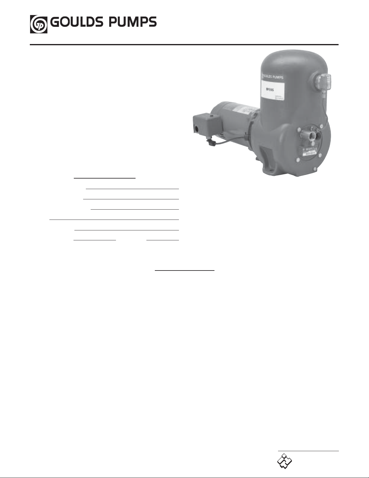
BF03S
BF03S
Installation and
Operation Manual
Owner’s Information
Owner’s Information
Pump Model Number:
Pump Serial Number:
Control Model Number:
Dealer:
Dealer Phone No.
Date of Purchase: Installation:
Table of Contents
Table of Contents
SUBJECT PAGE
Safety Instructions ........................................................... 2
Installation ..................................................................... 2
Suction Piping ................................................................. 2
Discharge Piping ............................................................. 2
Water Heaters ................................................................ 2
Wiring ........................................................................... 2
Installation With Positive Suction Head ............................. 3
Operation ...................................................................... 3
Priming Instructions ....................................................... 3
Maintenance .................................................................. 3
Mechancial Seal ............................................................. 3
Replacement of Mechanical Seal ...................................... 3
Locating Trouble ............................................................ 4
If Your Unit Fails To Function Properly ............................ 4
If Pump Runs But Does Not Deliver Water ....................... 4
Vacuum Gauge Method For Testing Suction..................... 5
SUBJECT PAGE
If Pump Delivers Water But Pressure Switch Does Not
Stop Pump When Water is Not Being Used ................... 5
If, After Pump Has Been In Service For Some Time,
It Pumps Water But Does Not Shut Off When Water
is Not Being Used ....................................................... 5
If Pump Starts and Stops Frequently When Water is
Not Being Used .......................................................... 5
Air Volume Control ........................................................ 6
Why It Is Necessary ....................................................... 6
How It Works ............................................................... 6
Water Logged (Air Cushioning Chamber) Casing .............. 6
If Water Leaks Around Air Volume Control ..................... 6
Seasonal Service .............................................................. 6
To Take Out of Service .................................................. 6
To Place Pump Back in Service ........................................ 6
Repair Parts .................................................................... 8
Limited Warranty ........................................................... 8
IM129R00
www.goulds.com
Goulds Pumps
ITT Industries
SAFETY INSTRUCTIONS
TO AVOID SERIOUS OR FATAL PERSONAL INJURY
OR MAJOR PROPERTY DAMAGE, READ AND
FOLLOW ALL SAFETY INSTRUCTIONS IN MANUAL
AND ON PUMP.
THIS MANUAL IS INTENDED TO ASSIST IN THE
INSTALLATION AND OPERATION OF THIS UNIT AND
MUST BE KEPT WITH THE PUMP.
This is a SAFETY ALERT SYMBOL.When
you see this symbol on the pump or in the
manual, look for one of the following signal
words and be alert to the potential for
personal injury or property damage.
DANGER
WARNING
CAUTION
NOTICE: INDICATES SPECIAL INSTRUCTIONS
THOROUGHLY REVIEW ALL INSTRUCTIONS AND
WARNINGS PRIOR TO PERFORMING ANY WORK
ON THIS PUMP.
MAINTAIN ALL SAFETY DECALS.
INSTALLATION
INSTALLATION
Unit should be mounted on a firm, level base and in a
convenient location, where it is protected from freezing.
Unit should not be completely enclosed as adequate clean
air for ventilation is necessary for proper operation of
motor and to prevent overheating.
If unit is installed in kitchen, sink cabinet, playroom or
other place where moisture might be objectionable it is
suggested that a pan be located under the entire unit to
catch the condensation drip that may collect on the unit
during humid weather.
Warns of hazards that WILL cause serious
personal injury, death or major property
damage.
Warns of hazards that CAN cause serious
personal injury, death or major property
damage.
Warns of hazards that CAN cause personal
injury or property damage.
WHICH AREVERY IMPORTANT AND
MUST BE FOLLOWED.
Air Volume Control
end to suction check valve on pump. Observe the following
instruction:
1. Use adequate pipe sizes, never smaller than
3
⁄4” except
under positive suction head (see page 3). Where total
pipe length between pump and source of supply is over
25 ft., use the following table to determine pipe size. An
increaser fitting will be required at pump.
TOTAL LENGTH OF
SUCTION PIPE BETWEEN
PUMP AND WELL
SIZE
SUCTION PIPE
UP TO 26’ TO 101’ TO
25’ 100’ 300’
3
⁄4”1”1
1
⁄4”
Note: The total suction lift, which includes the vertical
distance between the pumping level of the water and the
pump plus the friction loss in the pipe should not exceed
25 feet.
2. All piping or tubing should be inspected to make sure it
contains no scale, dirt or other foreign material that
might impair operation of pump.
3. All joints must be air tight. A good pipe compound
should be used.
4. A union should be installed in the suction line close to
the pump. Packed unions are preferable. If ground
unions are used they must be carefully aligned.
5. On suction lines 50 feet or more in length, a foot valve
can be used to lessen priming time. Install a tee in the
suction line for priming. When a foot valve is used,
prime pump through priming opening and suction line
through opening in tee.
6. Dug or drilled wells should be vented.
DISCHARGE PIPING
DISCHARGE PIPING
Connect house service pipe to 3⁄4” discharge opening. A gate
valve in the discharge line close to the pump will facilitate
working on pump without draining entire house system.
WATER HEATERS
WATER HEATERS
A check valve should be installed close to pump in the
discharge line between pump and water heater or other
heating appliance to prevent hot water from entering
pump. Be sure water heater or other heating device is
equipped with a temperature and pressure relief valve.
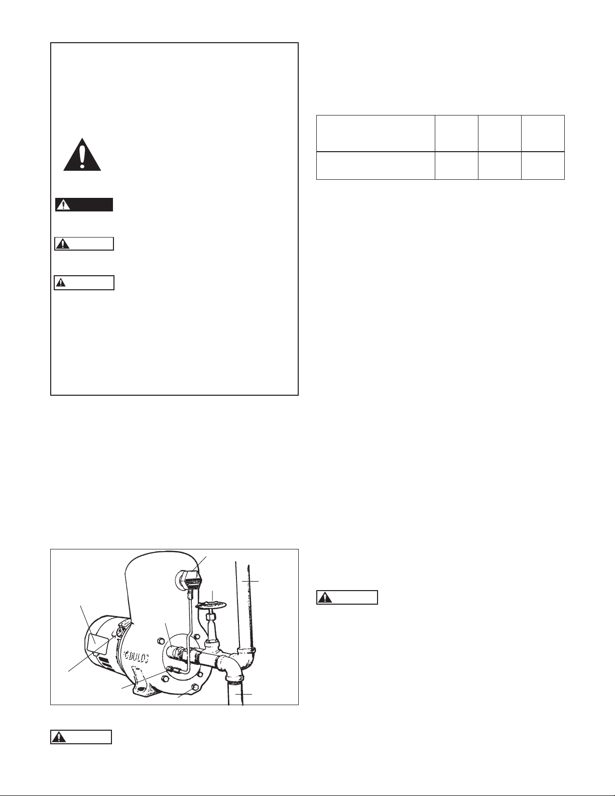
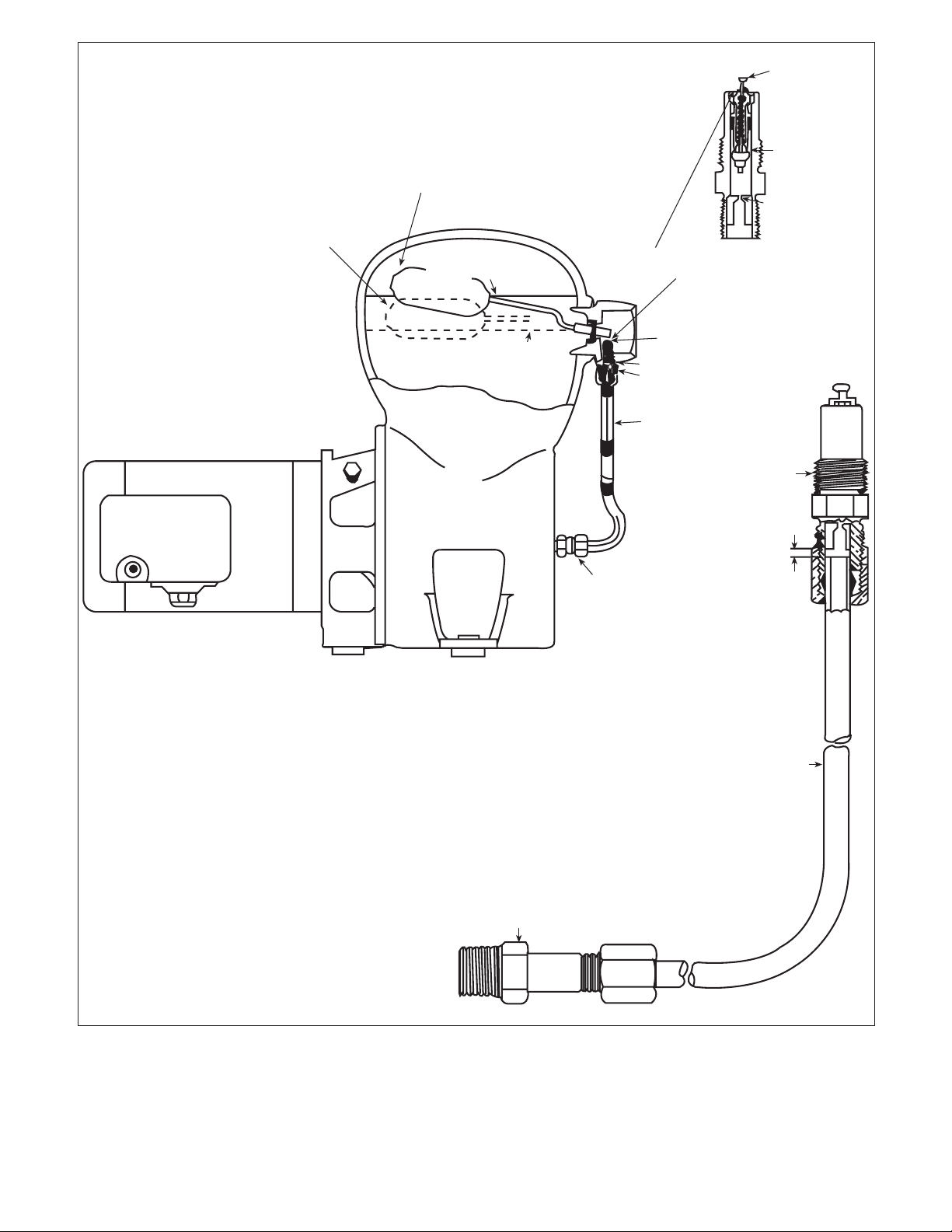
Pressure
Switch
Priming
Plug
SUCTION PIPING
SUCTION PIPING
WARNING
Air
Valve
Do not remove the suction check valve
even if a foot valve is used on other end of
Gate
Valve
Check
Valve
Drain Plug
Discharge
Suction
Figure 1
suction pipe. Run suction pipe to well, connecting pump
2
WIRING
WIRING
WARNING
Do not run pump until it has been filled to the
priming opening with clear water (see
PRIMING, page 3).
Standard motors furnished are 115/230V, single phase, 60
hz, A.C. motors.
Dual voltage motors will be wired for 115 volts. They can be
changed to 230 volts by following the instructions on the
motor or on the nameplate.
1. Use wire of sufficient size to maintain adequate voltage
at motor terminals while pump is running. Voltage
variations of plus or minus 10% from nameplate value
are allowable at motor terminals.
2. Motor circuits should be properly protected according
to NEC, CSA, state, provincial and local electric wiring
codes.
3. A manual disconnect switch should be located close to
the pump where required by code.
4. It is recommended this pump and motor be grounded in
accordance with prevailing electrical codes. Provisions
are provided for attaching ground wires to both motor
and pressure switch. Ground screws are located under
motor end cover and in the pressure switch.
IMPORTANT: After connecting wiring, DO NOT RUN
PUMP until it has been filled to priming opening with
clean water.
Connect power from a dedicated grounded circuit to the
Line terminals on the pressure switch. The connection
between the switch and the motor is made at the factory.
The circuit breaker should be OFF when the connections
are made by a qualified electrical technician.
INSTALLATION WITH POSITIVE
INSTALLATION WITH POSITIVE
SUCTION HEAD
SUCTION HEAD
On installations where the pump takes its water from a
source of supply that is at a higher elevation than the
pump, the pump operates under what is known as positive
suction head.
When the BF03S is used on this type of installation, install
a partially closed ball valve in the suction line to create
suction head at the pump.
To determine if a suction lift has been created, disconnect
tube from air volume control. With pump running, air
should be taken into tube. This can be determined by
placing finger over end of tube. When reconnecting tubing,
be careful not to cross the threads. Be sure the joint is air
tight.
OPERATION
OPERATION
WARNING
After making absolutely sure that the
power is OFF, remove the motor cover.
Check that the impeller turns freely. Turn the centrifugal
switch mechanism by hand or with a screwdriver. If the
shaft turns freely, reinstall the cover. On a new pump, if
the pump is bound the motor may have been damaged in
shipping. Return it to the place where purchased.
PRIMING INSTRUCTIONS
Prime the pump by removing the priming plug on the
motor adapter and filling the casing with water. It should
hold about 3 quarts. Replace the priming plug and open
the faucet closest to the pump. See Figure 1.
Pump is now ready to be started. Check all plumbing
connections and then turn power ON.
Pump should pick up prime within a few minutes. The
longer the suction pipe the longer it will take to prime. If
the pump does not prime, turn power OFF and check for
air leaks on suction piping and on the Air Volume
Control tubing and fittings. Repair all air leaks, refill
casing with water and start pump by turning power ON.
DANGER
The pressure switch adjustment must be
made with power ON and the pump motor
running. This adjustment should be made only by
qualified technicians familiar with working on “hot”
electrical devices. Remove the switch cover and locate
the tallest and largest spring/nut assembly. Turn the
hex nut counterclockwise to lower the cut-out pressure.
The safest tool to use is a
shaft, next best is a
3
⁄8” nut driver with a hollow
3
⁄8” box end wrench. One full turn
3
⁄8”
changes the setting 2 psi. After adjusting the OFF setting
it will be necessary to run through a cycle to insure that
the pump runs continuously when you use water. Do this
by opening 2 - 3 faucets for a few minutes and then close
them. Pump should go to approximately 40 psi and turn
OFF. Reinstall the switch cover and tighten the screw.
Note: extreme seasonal variations in the well water level
may require adjustments to the switch to prevent rapid
cycling or to allow the pump to shut off. The switch
adjustment instructions are on a label inside the switch
cover.
MAINTENANCE
MAINTENANCE
MECHANICAL SEAL
The mechanical shaft seal in this pump is not adjustable. If
a continuous and steady leak occurs around the shaft it is
an indication that the mechanical seal needs replacing. To
replace seal, observe the following instructions. See Repair
Parts page for part identification/nomenclature.
REPLACEMENT OF MECHANCIAL SEAL
To Dismantle:
Turn off power on pump motor branch circuit and
disconnect line wires to pressure switch. Close valve in
house piping. Drain pump. For procedure, see Seasonal
Service Instructions.
Remove 8 hex bolts holding motor adapter to pump casing
and lift off rotating element assembly including motor and
motor adapter.
Place motor and rotating element assembly on table, bench
or other convenient working space and remove guide vane
bolts and take off guide vane. See figure 4.
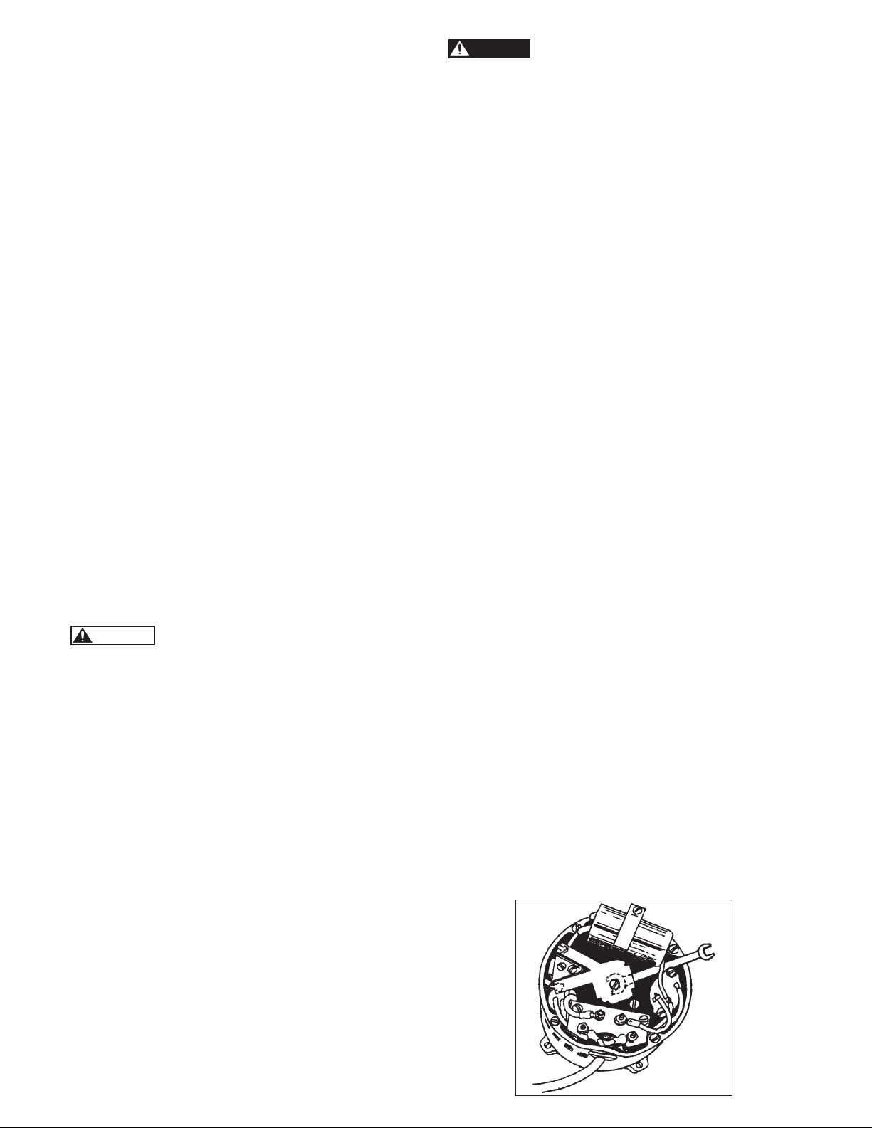
A.O. SMITH MOTORS - Remove motor end cover. Insert
7
⁄16” open end wrench, under switch mechanism onto flats
on motor shaft. While holding the shaft against rotating,
turn the impeller counterclockwise. The impeller should
turn completely off the shaft in this manner. See figure 2.
Using two screwdrivers, pry out rotary seal assembly. See
figure 3.
Using two small screwdrivers pry out the stationary seal
and Buna cup.
After the pump is fully primed, open a few more faucets.
When all air is expelled from the plumbing and the water
flows steadily close the faucets. Pressure should build up
to 40 psi and the switch should turn the pump OFF. The
pump is designed to run continuously whenever water is
being used and to turn OFF only when water usage
(flow) stops. If the switch does not go off it may require a
minor adjustment.
Figure 2
3
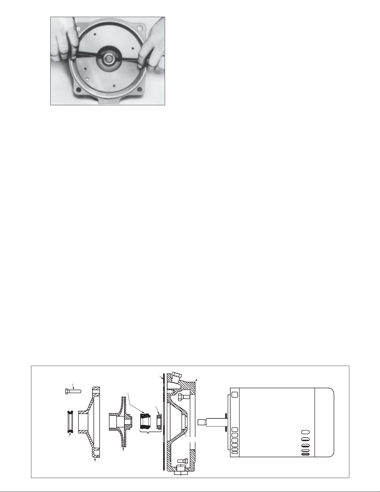
Figure 3
To Reassemble:
Be sure that recess for seal seat is free of all dirt and scale.
Apply a thin film of light oil to the recess of the motor
adapter and the neoprene bushing before installing the
new seal seat. This is a tight fit, but it must go in all the
way evenly or a leak will result. It can be pushed in with
the two thumbs. Do not mar lapped face of this seal. The
slightest scar or particle of dirt will cause a leak.
Assemble rotating member of seal on motor shaft.
Rotating seal face must fit snugly against lapped seal face
of stationary member in motor adapter. This is
accomplished by placing the rotating seal, sealing face
toward stationary seat, on the shaft. Use the impeller to
drive and seat the rotary seal.
Place gasket on motor adapter being careful the holes in
gasket line up with openings in the adapter. If gasket is
badly worn or has been damaged in any way, replace
with a new one.
While holding the shaft against rotating, as described in
A.O. Smith motors, page 3, screw impeller on shaft by
hand until tight against shoulder of motor shaft.
Replace guide vane, making sure that bore of guide vane
does not bind impeller hub, tightening screws alternately
and evenly. This can be checked by turning the motor
shaft. If binding occurs, loosen screws, re-adjust guide
vane until impeller hub turns freely, then tighten screws
as before.
Replace entire assembly in casing making sure gasket is
flat all the way around and has not been damaged. Also
check that the guide vane seal ring is in place on the
venturi.
Insert and tighten all casing bolts evenly.
Reconnect wires to pressure switch.
Close drain opening, using pipe joint compound on
threads of plug.
REFILL PUMP WITH WATER BEFORE STARTING.
See priming instructions.
LOCATING TROUBLE
LOCATING TROUBLE
IF YOUR UNIT FAILS TO FUNCTION PROPERLY
If your Goulds Pumps BF03S Water System fails to operate
properly after the foregoing instructions have been
followed, the trouble can usually be traced to certain
simple causes. Such as inadequate priming, air leaks in the
suction line, foreign matter in system, low voltage in power
line causing low motor speed, insufficient flow from well
or other source of supply, excessive suction lift, or a house
service line that is too small or too long causing excessive
friction loss. The following suggestions for locating
troubles should be followed in the order given, making sure
that each step does not remedy the trouble before trying
the next one.
IF PUMP RUNS BUT DOES NOT DELIVER WATER
NOTE: On long suction lines it may take considerable time
for the pump to exhaust all of the air in the
suction pipe and start to deliver water. When
starting the pump under these conditions, always
leave a faucet open for the air to escape. If there is
a foot valve on the end of the suction line, filling
the suction piping with water before starting will
shorten the time required for the pump to start
delivering water.
1. Examine pump by removing priming plug to see if if is
full of water. NOTE: Three quarts of water poured in
priming opening is sufficient to prime pump.
2. Check source of supply to see if there is an ample supply
of water available and that the end of suction pipe is
submerged in water but not buried in mud.
3. Check motor rotation. Make sure that motor runs in
direction indicated by arrow on pump casing cover.
Diagram Showing Dismantled Rotating Assembly
CASING
COVER
SEAL BORE
4
GUIDE VANE
BOLT
GUIDE VANE
SEAL RING
GUIDE
VANE
ROTATING
MEMBER
IMPELLER
GASKET
STATIONARY
MEMBER
MECHANICAL
SEAL
MOTOR
Figure 4

4. Disconnect the suction pipe at the check valve. Push the
valve stem with your finger to be sure it operates freely
and no foreign matter is present to prevent it seating.
5. Disconnect tube from air valve and place tire valve cap
on end of air valve. If pump primes OK it indicates that
the tube connections have been damaged and allow air
to leak into the suction of the pump. When reconnecting
copper tubing be sure threads are not crossed and the
connections are made air tight. See Procedure and
Diagram for making these connections.
VACUUM GAUGE METHOD FOR
TESTING SUCTION
Disconnect air volume control tube from air valve in pump
chamber. Remove air valve and insert vacuum gauge in 1⁄8”
pipe tapped opening in back plate. See figure 1. Run the
pump. If while pump is running, gauge does not register
vacuum it indicates:
A. Leak or leaks in the suction line.
B. End of suction pipe is not submerged.
If gauge registers a vacuum of 25” or more it indicates:
A. Plugged strainer on end of suction line or
strainer is buried in mud.
B. Suction check valve plugged or inoperative.
C. Too high a suction lift for satisfactory
operation.
If gauge registers a vacuum in feet that is less than the
vertical distance between the pump and the water in source
of supply, it indicates a leak which must be located and
eliminated. Most frequent causes of leaks in suction line are
ground unions, split pipes and fittings. Check these sources
for leaks first and repair them.
Remove vacuum gauge. Replace air valve. Reconnect
copper tube making sure all suction side connections are
tight, as they must be air tight.
If pump fails to function after vacuum gauge is removed
and air volume control is reconnected it indicates the tube
connections are not air tight.
IF PUMP DELIVERS WATER BUT PRESSURE
SWITCH DOES NOT STOP PUMP WHEN
WATER IS NOT BEING USED
To determine cause of the condition, proceed as follows:
1. Close valve in house piping system if one is installed. If
pump stops it indicates leaks in house piping. Examine
toilet flush valves, faucets, etc., for leaks.
2. Check motor rotation. Make sure that motor runs in
direction indicated by arrow on pump casing cover.
3. Check for excessive suction lift. To do this, see vacuum
gauge method under section “IF PUMP RUNS BUT
DOES NOT DELIVER WATER”, page 4. If suction lift is
beyond suction limits of pump, provision must be made
to reduce the suction lift by placing pump closer to
source of supply.
4. Pressure switch may need readjustment. See instructions
for setting pressure switch.
5. Check suction line for air leaks. See paragraph under
section “IF PUMP RUNS BUT DOES NOT DELIVER
WATER”, for method of doing this.
6. Air volume control tubing or fitting may be leaking air.
7. The nozzle might be plugged. In order to make a proper
examination of the nozzle and venturi, they must be
removed from the pump. To do this:
A. Disconnect power from pressure switch, close
gate valve in house piping and drain pump.
B. Remove 8 tap bolts holding case cover to case and
lift off rotating element assembly including motor
and case cover.
C. Disconnect the suction and discharge pipes and
copper tube from air valve.
D. Remove the 4 tap bolts holding the back plate
with nozzle and venturi to cushioning chamber
and remove this assembly from the chamber.
E. Venturi can be readily unscrewed and taken out
with a strap wrench or small pipe wrench.
F. To remove the nozzle use a 5⁄8” socket wrench.
G. Check number stamped on nozzle. This should be
015.
When replacing nozzle and venturi be sure they are
screwed in tightly as the shoulder of each must fit tight
against the machined surface of the back plate in order to
give the proper spacing of these parts, which is very
important for the satisfactory operation of the pump.
NOTE: It is recommended that thread on the plastic
venturi be lubricated with water. Be sure thread
starts properly and venturi is screwed in up to
shoulder.
CAUTION
placed and that the guide vane seal ring is in position on
the venturi.
IF, AFTER PUMP HAS BEEN IN SERVICE FOR SOME
TIME, IT PUMPS WATER BUT DOES NOT SHUT
OFF WHEN WATER IS NOT BEING USED
If pressure switch has been adjusted several times over a
long period of time and the condition is not corrected, it is
probable that the radial clearance between impeller hub
and guide vane is excessive. Remove rotating element and
check this clearance. If clearance is excessive (more than
.020”) or parts are deeply scored they should be replaced.
Install a new guide vane and impeller which will restore
pump to its original condition.
IF PUMP STARTS AND STOPS FREQUENTLY WHEN
WATER IS NOT BEING USED
1. Examine entire house piping system for leaks such as
dripping faucets and leaky flush tank valves and
eliminate any leaks.
2. Examine suction check valve. An obstruction on seat
would permit water to drain out of pump and cause
pump to start frequently. Make sure that suction check
valve stem moves freely in guide and that valve seats
tightly.
3. This condition of frequent starting and stopping when
water is not being drawn may be due to a lack of air in
the air cushioning chamber which may be caused by
improper operation of the Air Volume Control or Air
Valve.
When reassemblying the pump be sure the
gaskets are in good condition and properly
5

If a water-logged air cushioning chamber exists, when
water is not being used, which is indicated by a rapid
starting and stopping of the pump, recharge the air
cushioning chamber by disconnecting the copper tube from
the air valve, and let the pump run with a faucet open until
air comes out of the faucet. Then reconnect copper tube
with pump running. To prevent repetition of this condition
check air volume control and air valve.
AIR VOLUME CONTROL
AIR VOLUME CONTROL
This is not a standard Air Volume Control. Be sure to use
the special model supplied by Goulds Pumps for this unit as
it has a custom spring tension setting.
WHY IT IS NECESSARY
The turbulence of the water as it passes through the casing
causes it gradually to absorb air. Without air
replenishment, the water level would rise and soon there
would be no air in the cushioning chamber … a water
logged condition.
The Air Volume Control and Air Valve on Goulds Pumps
Balanced-Flow Water System are vitally important parts of
the unit. All connections to Air Volume Control and Air
Valve must be air tight. Without these parts operating
properly, satisfactory functioning of the entire unit cannot
be expected.
HOW IT WORKS
The Air Volume Control is installed in the tapped opening
in the air cushioning chamber. It must be connected to the
Air Valve in the body of the water pump with copper
tubing. See figure 5.
The float of the air volume control rises when the water
level rises. The extension of the float rod in the air volume
control (on the outside of the air cushioning chamber)
pushes the valve stem (1) in diagram down, opening valve.
This exposes the end of copper tubing to atmosphere
through hole in nameplate. Suction of the water pump
takes air in through this hole, down the tubing and into the
water pump through Air Valve (2). The air passes into the
air cushioning chamber with the water as it is discharged
from the water pump.
When there is sufficient air in the air cushioning chamber
the water level is at or below the level of the float valve,
valve (1) is closed and no air is drawn in until it is required.
WATER LOGGED (AIR CUSHIONING CHAMBER)
CASING
A pump casing is water logged when there is no air in it …
it is filled with water. It can be caused by:
1. Plugged orifice, damaged valve core or ruptured float on
air volume control. To check air volume control and air
valve, proceed as follows:
A. Disconnect copper tube from air volume
control. When pump is running, air should be
drawn into tube. If air is not drawn into tube, the
air valve may be plugged.
CAUTION
“INSTALLATION UNDER POSITIVE SUCTION
HEAD”, page 3.
Pump must have suction lift to draw
air through tube. See section
B. Remove air valve. Blow through it from tubing
connection side. If plugged, take it apart and
clean. Replace valve core if necessary.
C. Remove replacement valve assembly from the air
volume control and remove the valve core from
the valve body. Hold valve body to the light and if
you cannot see light through it, orifice is plugged.
Clean with a needle or very fine wire. If unable to
clean, replace with a new one.
If valve core is damaged, replace with a new one.
2. Air Volume Control may be inoperative due to
punctured float, broken float rod or ruptured diaphragm
around float rod. Replace with new one.
IF WATER LEAKS AROUND
AIR VOLUME CONTROL
1. Disconnect copper tubing at Air Volume Control. If leak
comes from tubing, Air Valve in water pump is leaking.
Replace valve core. See figure 5.
2. If water leaks from Air Volume Control when tubing is
disconnected, the control should be replaced.
SEASONAL SERVICE
SEASONAL SERVICE
TO TAKE OUT OF SERVICE
When pump is used during summer months and allowed to
stand idle during the winter, as in summer cottages, it is
necessary that the pump be thoroughly drained to prevent
damage from freezing. To drain unit proceed as follows:
1. Shut off power to pump motor branch circuit.
2. Drain house service lines.
3. Disconnect union in suction line and drain line. If there
is a foot valve on end of suction line it must be removed
and line drained.
4. Remove drain plug near bottom of air cushioning
chamber and allow all water to drain out. Removal of
priming plug will allow pump to vent while draining.
When removing drain plug make sure that tapped
opening from which plug is removed is not clogged with
scale or mud. If there is any question of foreign matter
in the opening, it should be cleaned out with a nail or
piece of stiff wire so that water will drain out freely.
5. After pump is completely drained, replace plugs.
TO PLACE PUMP BACK IN SERVICE
1. Make sure drain plug previously removed is tight. Use a
good joint compound on threads and screw in tightly.
2. If well pipes have been removed, reconnect them.
Examine faces of ground union. If scored, pitted or
imperfect, make packing of sheet rubber to insure tight
joint. If foot valve has been removed, reinstall.
3. Remove motor shaft end cap, insert screwdriver in
motor shaft slot and turn clockwise to make sure pump
is free.
4. Prime and start. See Priming and Starting and Setting
Switch Instructions.
6
NORMAL FLOAT POSITION
WITH CORRECT AIR CUSION
FLOAT CONTROL VALVE CLOSED.
FLOAT IN RAISED POSITION.
AIR SPACE
WATER LEVEL ABOVE
NORMAL CHAMBER NEEDS AIR.
NORMAL WATER LEVEL
WATER
SUCTION EFFECT OF WATER PUMP
WHEN RUNNING DRAWS AIR
THROUGH OPEN VALVE HERE.
VALVE STEM DEPRESSED BY
FLOAT ROD EXTENSION (1)
FLOAT CONTROLLED VALVE OPEN
CALIBRATED ORIFICE
AIR PASSES DOWN COPPER TUBE
INTO WATER PUMP THROUGH THE
AIR VALVE AND THEN INTO TANK
WITH THE WATER.
VALVE IS OPENED
BY DEPRESSING
THIS STEM.
VALVE SEAT
VALVE IS SHOWN IN
CLOSED POSITION.
CALIBRATED ORIFICE
VALVE ASSEMBLY
ON AIR VOLUME
CONTROL
AIR VALVE
IN PUMP CASING
1⁄16”
AIR VALVE (2)
3⁄16” O.D.
Copper Tubing
PROCEDURE FOR REPLACING AIR VOLUME
Slip compression nut and sleeve over end of tube and
insert end of tube all the way in counter bore of fitting.
Then pull tube back about 1⁄16” so there is a space
between end of tube and bottom of counter bore. With
tube in this position, tighten compression nut securely.
CONTROL TUBE IF DAMAGED
CAUTION: Be sure tube is in line with
counter bore and nut is not cross threaded.
Figure 5
7
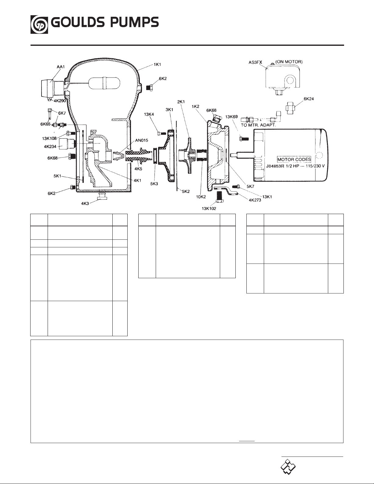
REPAIR PARTS
REPAIR PARTS
AA7 AND 4K4
Part No. Part Name
Pattern
No.
1K1 Casing with plug 52125
1K2 Motor adapter with plug and foot 52932
2K1 Impeller
3K1 Guidevane
4K1 Backplate 52126
4K3 Rubber grommet (optional)
4K4 Replacement valve core
(box of 12) for AA7
4K5 Venturi (diffuser)
4K273 Foot
4K234 Check valve
Part No. Part Name
6K2 Plug 1⁄4 NPT
6K7 Compression nut – A.V.C. tube
(use with 5K175)
6K24 Switch connector with nut
6K65 Tubing – A.V.C. (3⁄16" O.D.)
6K68 Plug 1⁄2 NPT
6K92 Switch tubing, polyproplene
6K94 Elbow tubing connector
6K100 Straight tubing connector
Pattern
No.
Part No. Part Name
10K2 Shaft seal assembly
13K1 Bolt – adapter to casing
13K4 Bolt – guidevane
13K69 Bolt – motor to adapter
13102 Bolt – foot to adapter
13K108 Bolt – backplate to casing
AA1 Air volume control
(includes 4K290)
AA7 Air valve (includes 4K4)
AN015 Nozzle
AS3FX Pressure switch
4K290 Replacement valve core for AA1
5K1 Gasket – backplate
5K2 Gasket – casing
5K3 Seal ring – guidevane
5K7 Deflector
5K175 O-ring connect A.V.C. tubing
to AA7
GOULDS PUMPS LIMITED WARRANTY
This warranty applies to all water systems pumps manufactured by Goulds Pumps.
Any part or parts found to be defective within the warranty period shall be replaced at no charge to the dealer during the warranty period. The warranty period shall exist for a
period of twelve (12) months from date of installation or eighteen (18) months from date of manufacture, whichever period is shorter.
A dealer who believes that a warranty claim exists must contact the authorized Goulds Pumps distributor from whom the pump was purchased and furnish complete details
regarding the claim. The distributor is authorized to adjust any warranty claims utilizing the Goulds Pumps Customer Service Department.
The warranty excludes:
(a) Labor, transportation and related costs incurred by the dealer;
(b) Reinstallation costs of repaired equipment;
(c) Reinstallation costs of replacement equipment;
(d) Consequential damages of any kind; and,
(e) Reimbursement for loss caused by interruption of service.
For purposes of this warranty, the following terms have these definitions:
(1) “Distributor” means any individual, partnership, corporation, association, or other legal relationship that stands between Goulds Pumps and the dealer in purchases,
consignments or contracts for sale of the subject pumps.
(2) “Dealer” means any individual, partnership, corporation, association, or other legal relationship which engages in the business of selling or leasing pumps to customers.
(3) “Customer” means any entity who buys or leases the subject pumps from a dealer. The “customer” may mean an individual, partnership, corporation, limited liability
company, association or other legal entity which may engage in any type of business.
THIS WARRANTY EXTENDS TO THE DEALER ONLY.
Goulds Pumps and the ITT Engineered Blocks Symbol are
registered trademarks and tradenames of ITT Industries.
©2002 Goulds Pumps
Printed in U.S.A.
Goulds Pumps
ITT Industries
8
Pattern
No.
 Loading...