

Page 1

IMPORTANT SAFETY NOTICE
To: Our Valued Customers
User safety is a major focus in the design of our products. Following the precautions outlined in this
manual will minimize your risk of injury.
ITT Goulds pumps will provide safe, trouble-free service when properly installed, maintained, and
operated.
Safe installation, operation, and maintenance of ITT Goulds Pumps equipment are an essential end user
responsibility. This Pump Safety Manual identifies specific safety risks that must be considered at all
times during product life. Understanding and adhering to these safety warnings is mandatory to ensure
personnel, property, and/or the environment will not be harmed. Adherence to these warnings alone,
however, is not sufficient — it is anticipated that the end user will also comply with industry and corporate
safety standards. Identifying and eliminating unsafe installation, operating and maintenance practices is
the responsibility of all individuals involved in the installation, operation, and maintenance of industrial
equipment.
Please take the time to review and understand the safe installation, operation, and maintenance guidelines
outlined in this Pump Safety Manual and the Instruction, Operation, and Maintenance (IOM) manual.
Current manuals are available at
your nearest Goulds Pumps sales representative.
www.gouldspumps.com/literature_ioms.html or by contacting
These manuals must be read and understood before installation and start-up.
For additional information, contact your nearest Goulds Pumps sales representative or visit our Web site at
www.gouldspumps.com.
S-1
Page 2

SAFETY WARNINGS
Specific to pumping equipment, significant risks bear reinforcement above and beyond normal safety precautions.
WARNING
A pump is a pressure vessel with rotating parts that can be hazardous. Any pressure vessel can explode,
rupture, or discharge its contents if sufficiently over pressurized causing death, personal injury, property
damage, and/or damage to the environment. All necessary measures must be taken to ensure over
pressurization does not occur.
WARNING
Operation of any pumping system with a blocked suction and discharge must be avoided in all cases.
Operation, even for a brief period under these conditions, can cause superheating of enclosed pumpage and
result in a violent explosion. All necessary measures must be taken by the end user to ensure this condition is
avoided.
WARNING
The pump may handle hazardous and/or toxic fluids. Care must be taken to identify the contents of the pump
and eliminate the possibility of exposure, particularly if hazardous and/or toxic. Potential hazards include, but
are not limited to, high temperature, flammable, acidic, caustic, explosive, and other risks.
WARNING
Pumping equipment Instruction, Operation, and Maintenance manuals clearly identify accepted methods for
disassembling pumping units. These methods must be adhered to. Specifically, applying heat to impellers
and/or impeller retaining devices to aid in their removal is strictly forbidden. Trapped liquid can rapidly
expand and result in a violent explosion and injury.
ITT Goulds Pumps will not accept responsibility for physical injury, damage, or delays caused by a failure to
observe the instructions for installation, operation, and maintenance contained in this Pump Safety Manual or the
current IOM available at www.gouldspumps.com/literature.
S-2
Page 3

SAFETY
DEFINITIONS
Throughout this manual the words WARNING, CAUTION, ELECTRICAL, and ATEX are used to indicate
where special operator attention is required.
Observe all Cautions and Warnings highlighted in this Pump Safety Manual and the IOM provided with
your equipment.
WARNING
Indicates a hazardous situation which, if not avoided, could result in death or serious injury.
Example: Pump shall never be operated without coupling guard installed correctly.
CAUTION
Indicates a hazardous situation which, if not avoided, could result in minor or moderate injury.
Example: Throttling flow from the suction side may cause cavitation and pump damage.
ELECTRICAL HAZARD
Indicates the possibility of electrical risks if directions are not followed.
Example: Lock out driver power to prevent electric shock, accidental start-up, and physical injury.
When installed in potentially explosive atmospheres, the instructions that follow the Ex symbol must be
followed. Personal injury and/or equipment damage may occur if these instructions are not followed. If there
is any question regarding these requirements or if the equipment is to be modified, please contact an ITT
Goulds Pumps representative before proceeding.
Example:
parts, resulting in a spark and heat generation.
Improper impeller adjustment could cause contact between the rotating and stationary
S-3
Page 4

GENERAL PRECAUTIONS
WARNING
A pump is a pressure vessel with rotating parts that can be hazardous. Hazardous fluids may be contained by the
pump including high temperature, flammable, acidic, caustic, explosive, and other risks. Operators and
maintenance personnel must realize this and follow safety measures. Personal injuries will result if procedures
outlined in this manual are not followed. ITT Goulds Pumps will not accept responsibility for physical injury,
damage or delays caused by a failure to observe the instructions in this manual and the IOM provided with your
equipment.
WARNING
WARNING
WARNING
WARNING
WARNING
WARNING
WARNING
WARNING
WARNING
WARNING
General Precautions
NEVER APPLY HEAT TO REMOVE IMPELLER. It may explode due to
trapped liquid.
NEVER use heat to disassemble pump due to risk of explosion from tapped liquid.
NEVER operate pump without coupling guard correctly installed.
NEVER operate pump without safety devices installed.
NEVER run pump below recommended minimum flow when dry, or without
prime.
ALWAYS lock out power to the driver before performing pump maintenance.
NEVER operate pump with discharge valve closed.
NEVER operate pump with suction valve closed.
DO NOT change service application without approval of an authorized ITT
Goulds Pumps representative.
Safety Apparel:
Insulated work gloves when handling hot bearings or using bearing heater
Heavy work gloves when handling parts with sharp edges, especially
impellers
Safety glasses (with side shields) for eye protection
Steel-toed shoes for foot protection when handling parts, heavy tools, etc.
Other personal protective equipment to protect against hazardous/toxic fluids
Receiving:
Assembled pumping units and their components are heavy. Failure to properly lift
and support equipment can result in serious physical injury and/or equipment
WARNING
WARNING
damage. Lift equipment only at specifically identified lifting points or as
instructed in the current IOM. Current manuals are available at
www.gouldspumps.com/literature_ioms.html or from your local ITT Goulds
Pumps sales representative. Note: Lifting devices (eyebolts, slings, spreaders, etc.)
must be rated, selected, and used for the entire load being lifted.
Alignment:
Shaft alignment procedures must be followed to prevent catastrophic failure of
drive components or unintended contact of rotating parts. Follow coupling
manufacturer’s coupling installation and operation procedures.
S-4
Page 5

WARNING
CAUTION
General Precautions
Before beginning any alignment procedure, make sure driver power is locked out.
Failure to lock out driver power will result in serious physical injury.
Piping:
Never draw piping into place by forcing at the flanged connections of the pump.
This may impose dangerous strains on the unit and cause misalignment between
pump and driver. Pipe strain will adversely effect the operation of the pump
resulting in physical injury and damage to the equipment.
WARNING
WARNING
WARNING
WARNING
WARNING
WARNING
WARNING
WARNING
WARNING
WARNING
WARNING
CAUTION
CAUTION
WARNING
Flanged Connections:
Use only fasteners of the proper size and material.
Replace all corroded fasteners.
Ensure all fasteners are properly tightened and there are no missing fasteners.
Startup and Operation:
When installing in a potentially explosive environment, please ensure that the
motor is properly certified.
Operating pump in reverse rotation may result in contact of metal parts, heat
generation, and breach of containment.
Lock out driver power to prevent accidental start-up and physical injury.
The impeller clearance setting procedure must be followed. Improperly setting
the clearance or not following any of the proper procedures can result in sparks,
unexpected heat generation and equipment damage.
If using a cartridge mechanical seal, the centering clips must be installed and set
screws loosened prior to setting impeller clearance. Failure to do so could result
in sparks, heat generation, and mechanical seal damage.
The coupling used in an ATEX classified environment must be properly certified
and must be constructed from a non-sparking material.
Never operate a pump without coupling guard properly installed. Personal injury
will occur if pump is run without coupling guard.
Make sure to properly lubricate the bearings. Failure to do so may result in excess
heat generation, sparks, and / or premature failure.
The mechanical seal used in an ATEX classified environment must be properly
certified. Prior to start up, ensure all points of potential leakage of process fluid to
the work environment are closed.
Never operate the pump without liquid supplied to mechanical seal. Running a
mechanical seal dry, even for a few seconds, can cause seal damage and must be
avoided. Physical injury can occur if mechanical seal fails.
Never attempt to replace packing until the driver is properly locked out and the
coupling spacer is removed.
WARNING
WARNING
Dynamic seals are not allowed in an ATEX classified environment.
DO NOT operate pump below minimum rated flows or with suction and/or
discharge valve closed. These conditions may create an explosive hazard due to
vaporization of pumpage and can quickly lead to pump failure and physical injury.
S-5
Page 6

WARNING
WARNING
WARNING
WARNING
WARNING
CAUTION
CAUTION
WARNING
CAUTION
CAUTION
General Precautions
Ensure pump is isolated from system and pressure is relieved before
disassembling pump, removing plugs, opening vent or drain valves, or
disconnecting piping.
Shutdown, Disassembly, and Reassembly:
Pump components can be heavy. Proper methods of lifting must be employed to
avoid physical injury and/or equipment damage. Steel toed shoes must be worn at
all times.
The pump may handle hazardous and/or toxic fluids. Observe proper
decontamination procedures. Proper personal protective equipment should be
worn. Precautions must be taken to prevent physical injury. Pumpage must be
handled and disposed of in conformance with applicable environmental
regulations.
Operator must be aware of pumpage and safety precautions to prevent physical
injury.
Lock out driver power to prevent accidental startup and physical injury.
Allow all system and pump components to cool before handling them to prevent
physical injury.
If pump is a Model NM3171, NM3196, 3198, 3298, V3298, SP3298, 4150, 4550,
or 3107, there may be a risk of static electric discharge from plastic parts that are
not properly grounded. If pumped fluid is non-conductive, pump should be
drained and flushed with a conductive fluid under conditions that will not allow
for a spark to be released to the atmosphere.
Never apply heat to remove an impeller. The use of heat may cause an explosion
due to trapped fluid, resulting in severe physical injury and property damage.
Wear heavy work gloves when handling impellers as sharp edges may cause
physical injury.
Wear insulated gloves when using a bearing heater. Bearings will get hot and can
cause physical injury.
S-6
Page 7

ATEX CONSIDERATIONS and INTENDED USE
Special care must be taken in potentially explosive environments to ensure that the equipment is properly
maintained. This includes but is not limited to:
1. Monitoring the pump frame and liquid end temperature.
2. Maintaining proper bearing lubrication.
3. Ensuring that the pump is operated in the intended hydraulic range.
The ATEX conformance is only applicable when the pump unit is operated within its intended use. Operating,
installing or maintaining the pump unit in any way that is not covered in the Instruction, Operation, and
Maintenance manual (IOM) can cause serious personal injury or damage to the equipment. This includes any
modification to the equipment or use of parts not provided by ITT Goulds Pumps. If there is any question
regarding the intended use of the equipment, please contact an ITT Goulds representative before proceeding.
Current IOMs are available at
Pumps Sales representative.
All pumping unit (pump, seal, coupling, motor and pump accessories) certified for use in an ATEX classified
environment, are identified by an ATEX tag secured to the pump or the baseplate on which it is mounted. A
typical tag would look like this:
www.gouldspumps.com/literature_ioms.html or from your local ITT Goulds
The CE and the Ex designate the ATEX compliance. The code directly below these symbols reads as follows:
II = Group 2
2 = Category 2
G/D = Gas and Dust present
T4 = Temperature class, can be T1 to T6 (see Table 1)
Table 1
Max permissible
surface temperature
Code
T1 842 (450) 700 (372)
T2 572 (300) 530 (277)
T3 392 (200) 350 (177)
T4 275 (135) 235 (113)
T5 212 (100) Option not available
T6 185 (85) Option not available
o
F (oC)
The code classification marked on the equipment must be in accordance with the specified area where the
equipment will be installed. If it is not, do not operate the equipment and contact your ITT Goulds Pumps sales
representative before proceeding.
Max permissible
liquid temperature
o
F (oC)
S-7
Page 8

PARTS
The use of genuine Goulds parts will provide the safest and
most reliable operation of your pump. ITT Goulds Pumps ISO
certification and quality control procedures ensure the parts are
manufactured to the highest quality and safety levels.
Please contact your local Goulds representative for details on
genuine Goulds parts.
S-8
Page 9

SPARE PARTS
RECOMMENDED SPARE PARTS . . . . . . . . . . . . . . . . . . . . 111
INTERCHANGEABILITY . . . . . . . . . . . . . . . . . . . . . . . . . 112
APPENDIX I Frame Lubrication Conversion . . . . . . . . . 119
APPENDIX II Installation Instructions for . . . . . . . . . . 123
ITT Goulds ANSI B15.1 Coupling Guards
APPENDIX III Alignment . . . . . . . . . . . . . . . . . . . . 127
APPENDIX IV Labyrinth Seal Installation Instructions . . . . 131
APPENDIX V C-Face Adapter Installation Instructions. . . . 133
APPENDIX VI 3198 Teflon® Sleeve Field Replacement . . . . 135
Procedure
APPENDIX VII-1 Double Row Angular Bearing . . . . . . . . . 137
Installation Instructions
APPENDIX VII-2 Duplex Angular Contact Bearing . . . . . . . . 139
Installation Instructions
APPENDIX VIII INPRO Labyrinth Oil Seal . . . . . . . . . . . . 141
Installation Instructions
When ordering spare parts, always state ITT Goulds Serial No. and indicate part name and
item number from relevant sectional drawing. It is imperative for service reliability to have a
sufficient stock of readily available spares.
RECOMMENDED SPARE PARTS
Impeller (101)
•
Shaft (122A)
•
Shaft Sleeve (126)
•
Outboard Bearing (112A)
•
Inboard Bearing (168A)
•
Casing Gasket (351)
•
Frame-to-Adapter Gasket (360D)
•
Bearing Housing Retaining Ring (361A)
•
Bearing Lockwasher (382)
•
Bearing Locknut (136)
•
Impeller O-Ring (412A)
•
Bearing Housing O-Ring (496)
•
Outboard Labyrinth Seal Rotary O-Ring (497F)
•
Outboard Labyrinth Seal Stationary O-Ring (497G)
•
Inboard Labyrinth Seal Rotary O-Ring (497H)
•
Inboard Labyrinth Seal Stationary O-Ring (497J)
•
Lantern Ring Half (105) (Packed Stuffing Box)
•
Stuffing Box Packing (106) (Packed Stuffing Box)
•
Packing Gland (107) (Packed Stuffing Box)
•
Impeller Gasket (428D) XLT-X & X17
•
7
ANSIFAM IOM - 5/08
111
Page 10
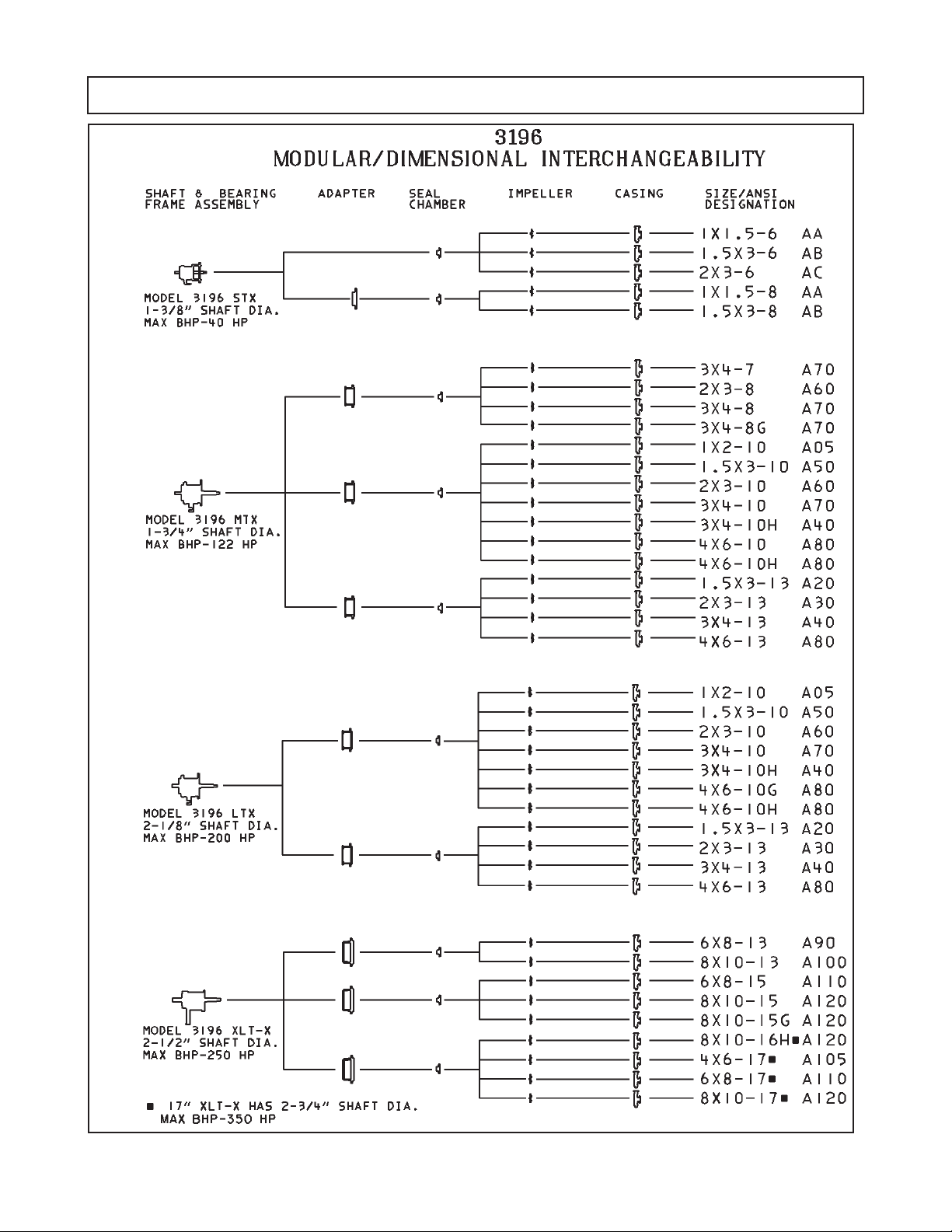
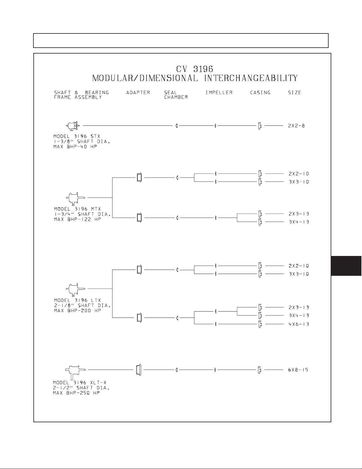
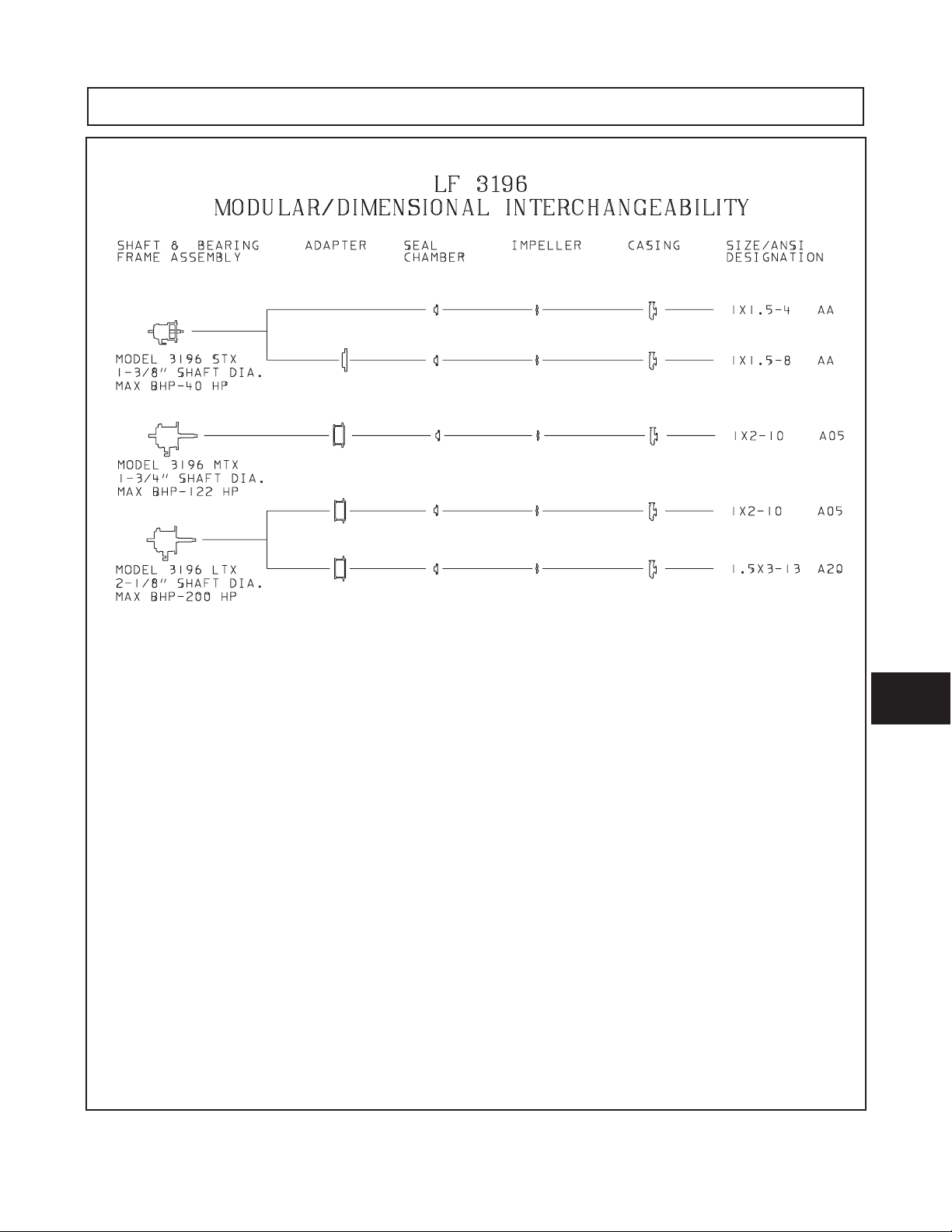
INTERCHANGEABILITY
112 ANSIFAM IOM - 5/08
Page 11
INTERCHANGEABILITY
7
ANSIFAM IOM - 5/08 113
Page 12

INTERCHANGEABILITY
114 ANSIFAM IOM - 5/08
Page 13
INTERCHANGEABILITY
7
ANSIFAM IOM - 5/08 115
Page 14

INTERCHANGEABILITY
116 ANSIFAM IOM - 5/08
Page 15

INTERCHANGEABILITY
7
ANSIFAM IOM - 5/08 117
Page 16

INTERCHANGEABILITY
118 ANSIFAM IOM - 5/08
Page 17

APPENDIX I
Frame Lubrication Conversion
Lubrication Conversion
Pumpage Temperature
below 350°F (177°C)
NLGI Consistency 2 3
Mobil Mobilux EP2 SCH32
Exxon Unirex N2 Unirex N3
Sunoco Multipurpose 2EP
SKF LGMT 2 LGMT 3
Pumpage Temperature
above 350°F (177°C)
Pumpage temperatures above 350°F (177°C) should
be lubricated by a high temperature grease. Mineral
oil greases should have oxidation stabilizers and a
consistency of NLGI 3.
NOTE: If it is necessary to change grease type
or consistency, the bearings must be removed
and the old grease removed.
!
l
Never mix greases of different consistency (NLGI
1 or 3 with NLGI 2) or different thickener soaps
(sodium or calcium with lithium). The consistency
usually becomes softer and will not provide
adequate lubrication to the bearings.
CAUTION
FRAME LUBRICATION CONVERSION
Conversion from Flood Oil to Pure Oil Mist
There are several ways to apply oil mist. ITT Goulds
has designed X-Series Power Ends to accept a
variety of oil mist configurations. The following
instructions are written for two popular systems in
use.
NOTE: Make sure that pipe threads are clean
and apply thread sealant to plugs & fittings.
NOTE: The LTX requires that the bearing
housing be changed when making the
conversion from flood oil to oil mist lubrication.
After the proper bearing housing has been
installed follow the instructions as they apply
to STX, MTX, XLT-X, X17.
A. Non-Vented Oil Mist System
1. Attach oil mist inlet to
outboard end of frame (plugged with 408H allen
head plug), and top, center of frame (plugged with
113A hex head plug).
2. Attach drain at bottom center of frame
hole (plugged with 408A magnetic drain plug).
1
" NPT connection at top,
4
3
" NPT
8
operation.
B. Vented Oil Mist System
1. Attach oil mist inlet connection to
connections at outboard and inboard ends of
frame.
2. Attach vent connection at
top center of frame.
3. Attach drain connection at
bottom center of frame (plugged with 408A
magnetic drain plug).
4. Follow oil mist generator manufacturer’s
instructions for oil mist volume adjustment and
operation.
l
!
Oil mist falls under Title III of the Clean Air Act
and must be controlled or the user will be
subject to penalty.
CAUTION
1
1
" NPT
4
" NPT hole located in
2
3
" NPT hole located at
8
8
3. Follow oil mist generator manufacturer’s
instructions for oil mist volume adjustment, and
ANSIFAM IOM - 5/08
119
Page 18

Conversion from Flood Oil to Regreaseable
NOTE: Make sure that pipe threads are clean
and apply thread sealant to plugs and fittings.
NOTE: LTX regreaseable power end requires a
changeout of the bearing housing and bearing
clamp ring. This housing provides a grease
path to the bearings.
1. Plug inboard oil return in bearing frame.
STX: Use epoxy, keep drilled hole clear.
MTX, LTX, XLT-X, X17: Use set screw, install
from adapter side, bottom in hole.
2. Plug outboard oil return slot in bearing housing,
keep through holes clear. (does not apply to LTX)
3. Replace both bearings with single shield type.
Refer to Assembly Section for installation
guidelines.(Ref. Bearing Chart Table 11)
4. Install grease fittings at top, inboard and top,
outboard
(plugged with 408H allen head plug).
5. Remove 2 (408H) Allen head plugs from bottom
side of frame prior to greasing bearings. Reinstall
hex head plugs (113) after bearings have been
greased.
1
" NPT connections in bearing frame
4
X-Series Conversion from Greased for Life
or Regreaseable to Oil Lubricated Bearings
NOTE: LTX bearing housing and clamp ring are
not interchangeable between oil and grease
lubrication.
1. Remove plug from oil return slot in the frame,
under the radial bearing.
STX: Remove epoxy from return slot.
MTX, LTX, XLT-X, X-17: Remove set screw
installed in the oil return hole.
2. Remove plug from oil return hole in the bearing
housing (134). For LTX only, housing (134) and
clamp ring (253B) require replacement. Contact
ITT Goulds for price and availability.
3. Replace both bearings with unshielded, oil lube
bearings. Refer to Assembly Section for
installation guidelines. (Ref. Bearing Chart,
Table 11).
4. Grease fittings should be removed to prevent
accidental greasing. Quantity of two (2) plugs
(408H) are required to replace the two (2) grease
fittings (193).
120 ANSIFAM IOM - 5/08
Page 19

Item No. Size Description Qty.
113 1/4"-18 NPT Ext. Hex/square Head Pipe Plug 2
113A 1/2"-14 NPT Ext. Hex/square Head Pipe Plug 1
193 1/4"-18 NPT Grease Fitting 2
228 ---- Bearing Frame 1
241 ---- Frame Foot 1
370F 1/2" Hex Cap Screw 2
408A 3/8"-18 NPT Ext. Square Head Pipe Plug (magnetic) 1
408J 1/4"-18 NPT Ext. Hex/square Head Pipe Plug 1
408L 1/2"-14 NPT Square Countersunk Headless Pipe Plug 1
408M 1" 11-1/2" NPT Square Countersunk Headless Pipe Plug 1
319 1" 11-1/2" NPT Sight Window 1
529 1/2" Light Helical Spring Lock Washer 2
MTX
Grease Lube
ANSIFAM IOM - 5/08 121
8
Page 20

122 ANSIFAM IOM - 5/08
Page 21

APPENDIX II
Installation Instructions for ITT Goulds
ANSI B15.1 Coupling Guards
The coupling guard used in an Atex
classified environment must be
constructed from a non-sparking material.
! WARNING
s
Before assembly or disassembly of the coupling
guard is performed the motor must be
de-energized, the motor controller/starter put in a
locked-out position and a caution tag placed at the
starter indicating the disconnect. Replace
coupling guard before resuming normal operation
of the pump. ITT Goulds Pumps assumes no
liability for avoiding this practice.
XLT-X Align the end plate (pump end) to the
pump bearing housing so that the large slots on
the end plate clear the bearing housing tap bolts
and the small slots are aligned to the impeller
adjusting bolts. Attach the end plate to the
bearing housing using the jam nuts on the
impeller adjusting bolts as shown in Fig. II-3.
After the end plate is attached to the bearing
housing, the impeller clearance must be checked
and reset as explained in Section V - Preventive
Maintenance.
NOTE: Coupling adjustments should be
completed before proceeding with coupling
guard assembly.
STX, MTX, LTX
Fig. II-1
Simplicity of design allows complete assembly of the
coupling guard, including the end plate (pump end), in
about fifteen minutes. If the end plate is already in place,
assembly can be accomplished in about five minutes.
Assembly:
NOTE: If end plate (pump end) is already
installed, make any necessary coupling
adjustments and then proceed to Step 2.
1. STX, MTX, LTX - Align end plate (pump end) to the
Bearing Frame. (No impeller adjustment required.)
ANSIFAM IOM - 5/08
XLT-X
Fig. II-2
Fig. II-3
123
8
Page 22

2. Spread bottom of coupling guard half (pump end)
slightly and place over pump end plate as shown
in Fig. II-4. The annular groove in the guard half
is located around the end plate (Fig. II-5).
501B
DRIVER
ANNULAR
GROOVE
234A
ANNULAR GROOVE
234A
501B
Fig. II-4
Fig. II-6
NUT
WASHER
4. Spread bottom of coupling guard half (driver end)
slightly and place over coupling guard half (pump
end) so that annular groove in coupling guard half
(driver end) faces the motor as shown in Fig. II-8.
BOLT
Fig. II-7
Fig. II-5
3. After the coupling guard half (pump end) is
located around the end plate, secure it with a bolt,
nut and two (2) washers through the round hole at
the front end of the guard half as shown in Fig.
II-6. Tighten securely (Fig. II-7).
ANNULAR
501B
GROOVE
DRIVER
Fig. II-8
124 ANSIFAM IOM - 5/08
Page 23

5. Place end plate (driver end) over motor shaft as
shown in Fig. II-9. Locate the end plate in the
annular groove at the rear of the coupling guard
half (driver end) and secure with a bolt, nut, and
two (2) washers through the round hole at the rear
of the guard half. Finger tighten only.
DRIVER
SLIDE TO FIT
DRIVER
6. Adjust length of coupling guard to completely
cover shafts and coupling as shown in Fig. II-10
by sliding coupling guard half (driver end) towards
motor. After adjusting guard length, secure with
bolt, nut and two (2) washers through the slotted
holes at the center of the guard and tighten.
Check all nuts on the guard assembly for
tightness.
! WARNING
s
Before assembly or disassembly of the
coupling guard is performed, the motor must
be de- energized, the motor controller/starter
put in a locked-out position and a caution tag
placed at the starter indicating the disconnect.
Replace coupling guard before resuming
normal operation if the pump. ITT Goulds
Pumps assumes no liability for avoiding this
practice.
234B
Fig. II-9
Fig. II-10
Disassembly
The coupling guard must be removed for certain
maintenance and adjustments to the pump, such as
adjustment of the coupling, impeller clearance
adjustment, etc. The coupling guard should be
replaced after maintenance is completed.
DO NOT resume normal pump operation with the
coupling guard removed.
NOTE: Refer to illustrations for assembly in
reverse order.
1. Remove nut, bolt, and washers from center
slotted hole in the coupling guard. Slide motor
end coupling guard half towards pump. Fig. II-10.
2. Remove nut, bolt, and washers from coupling
guard half (driver end), and remove end plate.
Fig. II-9.
3. Spread bottom of coupling guard half slightly and
lift off. Fig. II-8.
4. Remove remaining nut, bolt, and washers from
coupling guard half (pump end). Spread bottom
of coupling guard half slightly and lift off. Fig. II-4.
This completes disassembly of the coupling guard.
8
ANSIFAM IOM - 5/08
NOTE: It is not necessary to remove the end
plate (pump end) from the pump bearing
housing. The bearing housing tap bolts are
accessible without removing the end plate in
case maintenance of internal pump parts is
necessary. Before removing the pump bearing
housing, refer to Section 6 - Disassembly &
Reassembly.
125
Page 24

126 ANSIFAM IOM - 5/08
Page 25

APPENDIX III
Alignment
Alignment procedures must be followed to
prevent unintended contact of rotating
parts. Follow coupling manufacturer’s
coupling installation and operation
procedures.
SET UP
1. Mount two dial indicators on one of the coupling
halves (X) so they contact the other coupling half
(Y) (Fig. III-1).
2. Check setting of indicators by rotating coupling
half X to ensure indicators stay in contact with
coupling half Y but do not bottom out. Adjust
indicators accordingly.
ANGULAR ALIGNMENT
A unit is in angular alignment when indicator A
(Angular indicator) does not vary by more that .002 in.
(.05 mm) as measured at four points 90° apart.
Vertical Correction (Top-to-Bottom)
1. Zero indicator A at top dead center (12 o’clock) of
coupling half Y.
2. Rotate indicators to bottom dead center
(6 o’clock). Observe needle and record reading.
3. Negative Reading - The coupling halves are
further apart at the bottom than at the top. Correct
by either raising the driver feet at the shaft end
(add shims) or lowering the driver feet at the other
end (remove shims), (Fig. III-2).
Positive Reading - The coupling halves are
closer at the bottom than at the top. Correct by
either lowering the driver feet at the shaft end
(remove shims) or raising the driver feet at the
other end (add shims).
Fig. III-1
MEASUREMENT
1. To ensure accuracy of indicator readings, always
rotate both coupling halves together so indicators
contact the same point on coupling half Y. This
will eliminate any measurement problems due to
runout on coupling half Y.
2. Take indicator measurements with driver feet
hold-down bolts tightened. Loosen hold down
bolts prior to making alignment corrections.
3. Take care not to damage indicators when moving
driver during alignment corrections.
ANSIFAM IOM - 5/08
8
Fig. III-2
4. Repeat steps 1-3 until indicator A reads .002 in
(.05 mm) or less.
Horizontal Correction (Side-to-Side)
1. Zero indicator A on left side of coupling half Y, 90°
from top dead center (9 o’clock).
2. Rotate indicators through top dead center to the
right side, 180° from the start (3 o’clock). Observe
needle and record reading.
3. Negative Reading - The coupling halves are
further apart on the right side than the left. Correct
by either sliding the shaft end of the driver to the
left or the other end to the right.
127
Page 26

3. Positive Reading - The coupling halves are
closer together on the right side than the left.
Correct by either sliding the shaft end of the driver
to the right or the other end to the left (Fig. III-3).
Fig. III-3
4. Repeat steps 1 through 3 until indicator A reads
.002 in. (.05 mm) or less.
5. Re-check both horizontal and vertical readings to
ensure adjustment of one did not disturb the
other. Correct as necessary.
PARALLEL ALIGNMENT
A unit is in parallel alignment when indicator P
(parallel indicator) does not vary by more than .002 in.
(.05 mm) as measured at four points 90° apart at
operating temperature. Note the preliminary vertical
cold setting criteria, Table 1.
Vertical Correction (Top-to-Bottom)
1. Zero indicator P at top dead center of coupling
(12 o’clock) half Y (Fig. III-1).
2. Rotate indicator to bottom dead center (6 o’clock).
Observe needle and record reading.
Fig. III-4
NOTE: Equal amounts of shims must be added
to or removed from each driver foot. Otherwise
the vertical angular alignment will be affected.
4. Repeat steps 1 through 3 until indicator P reads
within .002 in. (.05 mm) or less when hot, or per
Table 1 when cold.
Horizontal Correction (Side-to-Side)
1. Zero indicator P on the left side of coupling half Y,
90° from top dead center (9 o’clock).
2. Rotate indicators through top dead center to the
right side, 180° from the start (3 o’clock). Observe
needle and record reading.
3. Negative Reading - Coupling half Y is to the left
of coupling half X. Correct by sliding driver evenly
in the appropriate direction (Fig. III-5).
Positive Reading - Coupling half Y is to the right
of coupling half X. Correct by sliding driver evenly
in the appropriate direction.
3. Negative Reading - Coupling half X is lower than
coupling half Y. Correct by removing shims of
thickness equal to half of the indicator reading
under each driver foot.
Positive Reading - Coupling half X is higher than
coupling half Y. Correct by adding shims of
thickness equal to half of the indicator reading
from each driver foot (Fig. III-4).
Fig. III-5
NOTE: Failure to slide motor evenly will affect
horizontal angular correction.
4. Repeat steps 1 through 3 until indicator P reads
.002 in. (.05 mm) or less.
5. Re-check both horizontal and vertical readings to
ensure adjustment of one did not disturb the
other. Correct as necessary.
128 ANSIFAM IOM - 5/08
Page 27

COMPLETE ALIGNMENT
A unit is in complete alignment when both indicators A
(angular) and P (parallel) do not vary by more than .002
in. (.05 mm) as measured at four points 90° apart.
Horizontal Correction (Side-to-Side)
1. Zero indicators A and P on the left side of
coupling half Y, 90° from top dead center (9
o’clock).
Vertical Correction (Top-to-Bottom)
1. Zero indicators A and P at top dead center
(12 o’clock) of coupling half Y.
2. Rotate indicator to bottom dead center (6 o’clock).
Observe the needles and record the readings.
3. Make corrections as outlined previously.
2. Rotate indicators through top dead center to the
right side, 180° from the start (3 o’clock). Observe
the needle, measure and record the reading.
3. Make corrections as outlined previously.
4. Recheck both vertical and horizontal readings to
ensure adjustment of one did not disturb the
other. Correct as necessary.
NOTE: With experience, the installer will understand the interaction between angular and
parallel and will make corrections appropriately.
ANSIFAM IOM - 5/08
8
129
Page 28

130 ANSIFAM IOM - 5/08
Page 29

APPENDIX IV
Old JM Clipper CFT Design Labyrinth Seal Installation Instructions
Description of Operation
The labyrinth oil seal serves two functions. The first
being to exclude environmental contamination from
the power-end. This is accomplished with a series of
tight clearance fits between the stationary and rotor.
Any water that manages to enter the seal is
eliminated from the seal through a drain slot located
at the six o’clock position when installed.
On the oil side, a series of oil grooves are present to direct
any oil between the shaft and stationary back into the oil
sump through a drain slot at the six o’clock position.
®
O-rings are supplied as standard due to their
Viton
chemical resistance. The stationary uses an O-ring to fit
the labyrinth seal to the housing. The stator uses an
O-ring to fit the labyrinth to the housing. The rotor uses an
O-ring to seal along the shaft and to serve as the drive.
Installation Procedures
l
!
The ITT Goulds labyrinth oil seal is a one piece
assembly. Do not attempt to separate the rotor
and stator. Damage to the seal may result.
1. Assemble the power end per the instructions in
Section 6 - Disassembly & Reassembly.
l
!
The edges of the keyway can be sharp. Failure
to cover the keyway may result in a cut O-ring
and a damaged seal.
2. Wrap tape around the coupling end of the shaft to
cover the keyway.
CAUTION
CAUTION
3. Press the seal over the shaft into the thrust
bearing housing or thrust bearing end cover by
hand until the shoulder of the seal is seated
against the housing/cover.
NOTE: An O-ring lubricant is not required, but
can be used if desired. If used, be sure the
lubricant is compatible with the O-ring material
and plant standards.
4. For STX units: Press the seal over the shaft into
the bearing frame by hand until the shoulder of
the seal is seated against the frame.
For all other units: Once the frame adapter is
installed on the bearing frame, press the seal over
the shaft into the frame adapter by hand until the
shoulder of the seal is seated against the adapter.
NOTE: An O-ring lubricant is not required, but
can be used if desired. If used, be sure the
lubricant is compatible with the O-ring material
and plant standards.
NOTE: During start-up when the parts of the
labyrinth oil seal establish a voluntary running
clearance, a small amount of wear is experienced
as the parts are in contact. This wear produces a
carbon filled Teflon
diameter of the seal and at the drain slot. This is
the result of the two surfaces being smoothed,
similar to burnishing. A lubricant should not be
applied between the faces at installation. Once the
running clearance has been established, no further
wear is experienced and no decrease in seal
performance occurs as a result of the carbon/
®
Teflon
residue.
®
residue, visible at the outside
8
NOTE: The smooth surface of electrical tape
provides an excellent surface to slide the rotor
O-ring over.
ANSIFAM IOM - 5/08
131
Page 30

Labyrinth Oil Seal Conversion (After Oct. '03)
As of October 2003 ITT Goulds has standardized on
INPRO VBXX-D Brass Labyrinth Oil Seals over the
old JM Clipper CFT design. As a result of this
change, new part numbers have been assigned to the
old JM Clipper CFT design as follows:
Table IV-1
Labyrinth Oil Seal Conversion
Part Numbers
Old Part # New Part #
STX Frame (Outboard) D08717A01 D08717A44
STX Frame (Inboard) D08717A02 D08717A45
MTX (Outboard) D08717A03 D08717A46
MTX (Itboard) D08717A04 D08717A47
LTX (Outboard) D08717A05 D08717A48
LTX (Inboard) D08717A06 D08717A49
XLTX (Outboard) D08717A07 D08717A50
XLTX (Inboard) D08717A08 D08717A51
* 3198 MTX (Inboard) D08717A31 D08717A52
132 ANSIFAM IOM - 5/08
Page 31

APPENDIX V
C-Face Adapter Installation Instructions
Disassembly
1. Remove the motor by loosening the motor
mounting bolts (371). Refer to Table V-1 for the
number of bolts.
Table V-1
Number of Motor Bolts
Pump Frame Motor frame No. of Bolts
STX All 4
MTX
143-286 4
324-365 8
Fig. V-1
!
l
The motor may be heavy and should be
properly supported with a clean, uncorroded
eye bolt or a strap under both end bells.
NOTE: Use of a C-Face adapter will result in
one of the following configurations — a foot
mounted adapter with an overhung motor or an
unsupported adapter and a foot mounted motor.
2. Remove the C-Face adapter (340) from the pump
bearing frame (228A) by loosening the four bolts
(371N) attached to the bearing frame flange.
NOTE: Both coupling hubs do not need to be
removed.
CAUTION
Inspections
1. Visually inspect the C-face adapter (340) for
cracks. Check surfaces for rust, scale, or debris.
Remove all loose or foreign material (Fig. V-1).
2. Check for corrosion or pitting.
Reassembly
1. Mount both the pump and motor coupling hubs if
not already mounted.
2. Slide the C-Face adapter (340) over the pump
shaft (122) and mount against the pump bearing
frame (228A) flange using four bolts (371N).
Torque bolts to the values shown in Table V-2.
3. Mount the motor to the C-Face adapter (340)
using the four or eight motor bolts (371). Torque
bolts to the values shown in Table V-2.
Table V-2
Bolt Torque
Location Frame
C-face
adapter-to-
frame
C-face
adapter-to-
motor
STX
MTX
LTX
143TC-145TC
182TC-286TC
324TC-365TC
Lubricated
Threads
20 ft-lbs (27 N-m) 30 ft-lbs (40 Nm)
20 ft-lbs (27 N-m) 30 ft-lbs (40 Nm)
20 ft-lbs (27 N-m) 30 ft-lbs (40 Nm)
8 ft-lbs (11 N-m) 12 ft-lbs (16 Nm)
20 ft-lbs (27 N-m) 30 ft-lbs (40 Nm)
39 ft-lbs (53 N-m) 59 ft-lbs (80 Nm)
Dry
Threads
8
8
ANSIFAM IOM - 5/08 133
Page 32

Alignment
A shaft alignment is not required when using the C-Face
adapter. The rabbetted fits of the motor to the adapter
and the adapter to the bearing frame automatically
aligns the shaft to within the specified limits below.
The C-face motor adapter is intended for end users
who need fast pump installation. A C-face adapter
can attain a nominal alignment of 0.007 inches TIR.
However, due to the stack up of machining tolerances
of the various parts, the alignment can be as high as
0.015 inches TIR. Using a flexible, elastomer
coupling like a Rexnord ES or Wood's Sureflex will
provide acceptable pump and motor life under these
alignment conditions.
To achieve the best Mean Time Between Pump
Maintenance (MTBPM) requires shaft alignments of
less than 0.002 inches (0.05mm). End users who
require high pump and motor reliability are better
served by using a foot mounted motor on a precision
machined baseplate and performing a conventional
alignment.
134 ANSIFAM IOM - 5/08
Page 33

APPENDIX VI
3198 Teflon®Sleeve Field Replacement Procedure
The Model 3198 Teflon®sleeve is field replaceable,
provided a controlled oven capable of heating the
sleeve to 550° F (228° C) and a method of machining
the sleeve after installation on the shaft are available.
!
l
Do not heat the sleeve with an open flame.
Irreparable damage will occur to the sleeve.
For those users who do not have the above facilities,
shaft/sleeve sub-assemblies are available from ITT
Goulds.
1. Remove the old or damaged sleeve (126) from
the shaft (122). The sleeve may be cut
lengthwise with a sharp knife.
2. Thoroughly clean the shaft. Pay particular
attention to the knurled area of the shaft under the
sleeve.
NOTE: The replacement sleeve will not have
the same dimensions as the sleeve which was
removed until it is mounted on the shaft and
machined.
3. Heat the replacement sleeve in a controlled oven
at 550° F (288° C) for 40 minutes.
l
!
Do not heat the sleeve with an open flame —
irreparable damage will occur to the sleeve.
! WARNING
s
The oven and sleeve are hot. Use insulated gloves
to prevent burn injuries.
4. Remove the sleeve from the oven.
5. Slide the sleeve onto the shaft immediately after
removing it from the oven. Push the sleeve onto
the shaft until the sleeve bottoms out on the
shoulder of the shaft (Fig. VI-1). The hook end of
the sleeve will extend beyond the knurled portion
of the shaft.
CAUTION
CAUTION
6. As the sleeve cools, it will shrink in length. Apply
light pressure to keep the sleeve against the shaft
shoulder. Maintain pressure until the hook
portion of the sleeve seats itself against the
shoulder under the hook (Fig. V-2).
Fig. VI-2
!
l
Care must be taken not to damage the end of
the sleeve.
7. Allow the shaft and sleeve to cool completely.
8. Machine the Teflon
and finish shown in Table VI-1.
CAUTION
®
sleeve to the dimensions
Fig. VI-3
Table VI-1
3198 Teflon
®
Sleeve Diameter and Finish
Frame Sleeve OD Surface Finish
STX 1.375 / 1.373
MTX 1.750 / 1.748
9. Face off the sleeve shoulder even with and
parallel to the shaft shoulder (Fig. VI-4).
16 μ in.
16 μ in.
8
ANSIFAM IOM - 5/08
Fig. VI-4
Fig. VI-1
135
Page 34

136 ANSIFAM IOM - 5/08
Page 35

APPENDIX VII-1
Double Row Angular Contact Bearing Installation Instructions
1. Inspect the shaft (122) to ensure that it is clean,
dimensionally correct, and is free of nicks, burrs,
etc.
2. Lightly coat the bearing seating with a thin film of
oil.
3. Remove the bearing (112) from its packaging.
4. Wipe the preservative from the bearing (112) bore
and outer diameter.
5. Use an induction heater with a demagnetizing
cycle to heat bearing (112) to an inner ring
temperature of 230 °F (110 °C).
! WARNING
s
Wear insulated gloves when using a bearing
heater. Bearings will get hot and can cause
physical injury.
6. Position the bearing (112) on the shaft (122)
against the shoulder and snug the locknut (136)
against the bearing until it is cool. The locknut
prevents the bearing from moving away from the
shaft shoulder as it cools.
NOTE: Regreasable bearing has a single shield.
The outboard bearing is installed with shield
toward impeller.
7. Remove bearing locknut (136) after bearing (112)
has cooled.
8. Place lockwasher (382) on shaft (122). Place
tang of lockwasher in keyway of shaft.
9. Thread locknut (136) onto shaft (122). Tighten
locknut one-eighth (1/8) to one-quarter (1/4) turn
beyond snug. Bend any tang of lockwasher (382)
into a slot of locknut.
NOTE: Tighten locknut if necessary to align the
closest tab of lockwasher with slot on locknut,
but do not overtighten. See Table VII-1 for
maximum locknut torque.
Table VII-1
Maximum Bearing Locknut Torque
Torque
Group Bearing Size Locknut Size
STX 5306 N-06 20 (27)
MTX 5309 N-09 50 (68)
XLT-X, X17 5313 N-13 140 (190)
Ft-Lb (Nm)
Table VII-2
Maximum Bearing Locknut Torque
Maximum Torque
Group Bearing Size Locknut Size
STX 7306 N-06 20 (27)
MTX 7309 N-09 50 (68)
LTX 7310 N-10 70 (95)
XLT-X, X17 7313 N-13 140 (190)
ANSIFAM IOM - 5/08 137
Ft-Lb (N!m)
8
Page 36

138 ANSIFAM IOM - 5/08
Page 37

APPENDIX VII-2
Duplex Angular Contact Bearing Installation Instructions
1. Inspect the shaft (122) to ensure that it is clean,
dimensionally correct, and is free of nicks, burrs,
etc. (Fig. VII-1).
Fig. VII-1
2. Lightly coat the bearing seating with a thin film of oil.
3. Remove the bearings (112) from their packaging.
4. Wipe the preservative from the bearing (112) bore
and outer diameter.
7. Position the bearings (112) on the shaft (122)
against the shoulder and snug the locknut (136)
against the bearings until they are cool. The
locknut prevents the bearings from moving away
from the shaft shoulder as they cool. It is best to
rotate the outer bearing rings relative to each
other as they are placed on the shaft to assure
good alignment.
8. Remove bearing locknut (136) after bearings
(112) have cooled.
9. Place lockwasher (382) on shaft (122). Place
tang of lockwasher in keyway of shaft. (Fig. VII-2).
5. Use an induction heater with a demagnetizing
cycle to heat both bearings (112) to an inner ring
temperature of 230 °F (110 °C).
6. Place both bearings (112) on the shaft (122) with
the large outer races together (back to back).
l
! CAUTION
Duplex bearings are mounted back to back.
Make sure orientation of bearings is correct.
! WARNING
s
Wear insulated gloves when using a bearing
heater. Bearings will get hot and can cause
physical injury.
Fig. VII-2
10. Thread locknut (136) onto shaft (122). Tighten
locknut one-eighth (1/8) to one-quarter (1/4) turn
beyond snug. Bend any tang of lockwasher (382)
into a slot of locknut.
NOTE: Tighten locknut if necessary to align the
closest tab of lockwasher with slot on locknut,
but do not overtighten. Refer to Table VII-2 for
maximum locknut torque.
8
ANSIFAM IOM - 5/08 139
Page 38

140 ANSIFAM IOM - 5/08
Page 39

APPENDIX VIII
INPRO Labyrinth Oil Seal Installation Instructions
Description of Operation
The INRP VBXX-D®Labyrinth Oil Seal is specially
designed to protect pump bearings from lubrication
starvation as well as environmental contamination.
The bearing is made up of three basic parts: the rotor
(1), stator (2), and VBX
over the shaft and is held in place by an elastomeric
drive ring (4). The drive ring causes the rotor to turn
with the shaft and provides a positive, static seal
against the shaft. There is no metal-to-metal contact,
therefore, no friction or wear concerns.
®
Ring (3). The rotor (1) fits
Intallation Procedures
! CAUTION
l
The INPRO VBX is a one piece design. Do not
attempt to separate the rotor (1) from the stator
(2) prior to or during installation.
1. Assemble the power end per the instructions in
Section 6 - Disassembly and Reassembly.
l
! CAUTION
The edges of the keyway can be sharp. Failure
to cover the keyway with tape may result in a
cut o-ring and a damaged seal.
2. Wrap some electrical tape around the coupling
end of the shaft to cover the keyway.
NOTE: The smooth surface of the electrical
tape provides an excellent surface to slide the
rotor O-ring over.
3. Lightly lube the shaft and rotor drive ring (4) with
supplied lubricant.
NOTE: Lubricant will aid in the installation
process. If used, be sure the lubricant is
compatible with the O-ring material and plant
standards.
4. Use an arbor press to install the outboard INPRO
VBXX-D
port (6) at the 6 o'clock position. Press it only as far
as the beginning of the stator location ramp (9) and
avoid angular misalignment. There is nominal 0.002"
interference fit. Discard any residual material from
the stator gasket (5).
For STX Units
5. Press the inboard seal over the shaft into the
bearing frame as described in Step 4 above.
For All Other Units
5. Once the frame adapter is installed on the
bearing frame, press the inboard seal over the shaft
and into the adapter as descbied in Step 4 above.
®
into the bearing cover with the expulsion
8
ANSIFAM IOM - 5/08
Fig. VIII-1
141
Page 40

NOTES
__________________________________________________________________________________________
__________________________________________________________________________________________
__________________________________________________________________________________________
__________________________________________________________________________________________
__________________________________________________________________________________________
__________________________________________________________________________________________
__________________________________________________________________________________________
__________________________________________________________________________________________
__________________________________________________________________________________________
__________________________________________________________________________________________
__________________________________________________________________________________________
__________________________________________________________________________________________
__________________________________________________________________________________________
__________________________________________________________________________________________
__________________________________________________________________________________________
__________________________________________________________________________________________
__________________________________________________________________________________________
__________________________________________________________________________________________
__________________________________________________________________________________________
__________________________________________________________________________________________
__________________________________________________________________________________________
__________________________________________________________________________________________
__________________________________________________________________________________________
__________________________________________________________________________________________
__________________________________________________________________________________________
__________________________________________________________________________________________
__________________________________________________________________________________________
__________________________________________________________________________________________
142 ANSIFAM IOM - 5/08
Page 41

NOTES
__________________________________________________________________________________________
__________________________________________________________________________________________
__________________________________________________________________________________________
__________________________________________________________________________________________
__________________________________________________________________________________________
__________________________________________________________________________________________
__________________________________________________________________________________________
__________________________________________________________________________________________
__________________________________________________________________________________________
__________________________________________________________________________________________
__________________________________________________________________________________________
__________________________________________________________________________________________
__________________________________________________________________________________________
__________________________________________________________________________________________
__________________________________________________________________________________________
__________________________________________________________________________________________
__________________________________________________________________________________________
__________________________________________________________________________________________
__________________________________________________________________________________________
__________________________________________________________________________________________
__________________________________________________________________________________________
__________________________________________________________________________________________
__________________________________________________________________________________________
__________________________________________________________________________________________
__________________________________________________________________________________________
__________________________________________________________________________________________
__________________________________________________________________________________________
__________________________________________________________________________________________
ANSIFAM IOM - 5/08 143
Page 42

HOW TO ORDER
When ordering parts call
1-800-446-8537
or your local ITT Goulds Representative
EMERGENCY SERVICE
Emergency parts service is available
24 hours/day, 365 days/year . . .
Call 1-800-446-8537
Form No. IFAMILY Rev. 5/08
© copyright 2008 Goulds Pumps, Incorporated
a subsidiary of ITT Corporation
 Loading...