

Page 1
Installation, Operation and Maintenance Instructions
Model AF (6”-36”) MXR Bearings
Page 2

FOREWORD
This manual provides instructions for the Installation, Operation, and Maintenance of the
Goulds Axial Flow (AF) pump model. This manual covers the standard product. For special
options, supplemental instructions are supplied. This manual must be read and understood
before installation and start-up.
The design, materials and workmanship incorporated in the construction of Goulds pumps
makes them capable of giving long, trouble-free service. The life and satisfactory service of any
mechanical unit, however, is enhanced and extended by correct application, proper installation,
periodic inspection, condition monitoring and careful maintenance. This instruction manual was
prepared to assist operators in understanding the construction and the correct methods of
installing, operating, and maintaining these pumps.
Goulds shall not be liable for physical injury, damage or delays caused by a failure to
observe the instructions for Installation, Operation, and Maintenance contained in this
manual.
Warranty is valid only when genuine Goulds parts are used.
Use of the equipment on a service other than stated in the order will nullify the warranty,
unless written approval is obtained in advance from Goulds Pumps, Inc.
Supervision by an authorized Goulds representative is recommended to assure proper
installation.
Additional manuals can be obtained by contacting your local Goulds representative or by
calling 1-800-446-8537.
THIS MANUAL EXPLAINS
Proper Installation
Start-up Procedures
Operation Procedures
Routine Maintenance
Pump Overhaul
Trouble shooting
Order Spare or Repair Parts
AF (6-36) IOM
3
Page 3

TABLE OF CONTENTS
Page
9
11
15
31
37
SAFETY
GENERAL INFORMATION
INSTALLATION
OPERATION
PREVENTATIVE MAINTENANCE
Section
1
2
3
4
5
45
67
69
AF (6-36) IOM
DISASSEMBLY & RE-ASSEMBLY
SPARE PARTS
APPENDIX 1
6
7
8
7
Page 4

THIS PAGE
INTENTIONALLY
LEFT BLANK
8
AF (6-36) IOM
Page 5

IMPORTANT SAFETY NOTICE
To: Our Valued Customers
User safety is a major focus in the design of our products. Following the precautions outlined in this
manual will minimize your risk of injury.
ITT Goulds pumps will provide safe, trouble-free service when properly installed, maintained, and
operated.
Safe installation, operation, and maintenance of ITT Goulds Pumps equipment are an essential end user
responsibility. This Pump Safety Manual identifies specific safety risks that must be considered at all
times during product life. Understanding and adhering to these safety warnings is mandatory to ensure
personnel, property, and/or the environment will not be harmed. Adherence to these warnings alone,
however, is not sufficient — it is anticipated that the end user will also comply with industry and corporate
safety standards. Identifying and eliminating unsafe installation, operating and maintenance practices is
the responsibility of all individuals involved in the installation, operation, and maintenance of industrial
equipment.
Please take the time to review and understand the safe installation, operation, and maintenance guidelines
outlined in this Pump Safety Manual and the Instruction, Operation, and Maintenance (IOM) manual.
Current manuals are available at
your nearest Goulds Pumps sales representative.
www.gouldspumps.com/literature_ioms.html or by contacting
These manuals must be read and understood before installation and start-up.
For additional information, contact your nearest Goulds Pumps sales representative or visit our Web site at
www.gouldspumps.com.
S-1
Page 6
SAFETY WARNINGS
Specific to pumping equipment, significant risks bear reinforcement above and beyond normal safety precautions.
WARNING
A pump is a pressure vessel with rotating parts that can be hazardous. Any pressure vessel can explode,
rupture, or discharge its contents if sufficiently over pressurized causing death, personal injury, property
damage, and/or damage to the environment. All necessary measures must be taken to ensure over
pressurization does not occur.
WARNING
Operation of any pumping system with a blocked suction and discharge must be avoided in all cases.
Operation, even for a brief period under these conditions, can cause superheating of enclosed pumpage and
result in a violent explosion. All necessary measures must be taken by the end user to ensure this condition is
avoided.
WARNING
The pump may handle hazardous and/or toxic fluids. Care must be taken to identify the contents of the pump
and eliminate the possibility of exposure, particularly if hazardous and/or toxic. Potential hazards include, but
are not limited to, high temperature, flammable, acidic, caustic, explosive, and other risks.
WARNING
Pumping equipment Instruction, Operation, and Maintenance manuals clearly identify accepted methods for
disassembling pumping units. These methods must be adhered to. Specifically, applying heat to impellers
and/or impeller retaining devices to aid in their removal is strictly forbidden. Trapped liquid can rapidly
expand and result in a violent explosion and injury.
ITT Goulds Pumps will not accept responsibility for physical injury, damage, or delays caused by a failure to
observe the instructions for installation, operation, and maintenance contained in this Pump Safety Manual or the
current IOM available at www.gouldspumps.com/literature.
S-2
Page 7
SAFETY
DEFINITIONS
Throughout this manual the words WARNING, CAUTION, ELECTRICAL, and ATEX are used to indicate
where special operator attention is required.
Observe all Cautions and Warnings highlighted in this Pump Safety Manual and the IOM provided with
your equipment.
WARNING
Indicates a hazardous situation which, if not avoided, could result in death or serious injury.
Example: Pump shall never be operated without coupling guard installed correctly.
CAUTION
Indicates a hazardous situation which, if not avoided, could result in minor or moderate injury.
Example: Throttling flow from the suction side may cause cavitation and pump damage.
ELECTRICAL HAZARD
Indicates the possibility of electrical risks if directions are not followed.
Example: Lock out driver power to prevent electric shock, accidental start-up, and physical injury.
When installed in potentially explosive atmospheres, the instructions that follow the Ex symbol must be
followed. Personal injury and/or equipment damage may occur if these instructions are not followed. If there
is any question regarding these requirements or if the equipment is to be modified, please contact an ITT
Goulds Pumps representative before proceeding.
Example:
parts, resulting in a spark and heat generation.
Improper impeller adjustment could cause contact between the rotating and stationary
S-3
Page 8

GENERAL PRECAUTIONS
WARNING
A pump is a pressure vessel with rotating parts that can be hazardous. Hazardous fluids may be contained by the
pump including high temperature, flammable, acidic, caustic, explosive, and other risks. Operators and
maintenance personnel must realize this and follow safety measures. Personal injuries will result if procedures
outlined in this manual are not followed. ITT Goulds Pumps will not accept responsibility for physical injury,
damage or delays caused by a failure to observe the instructions in this manual and the IOM provided with your
equipment.
General Precautions
WARNING
WARNING
NEVER use heat to disassemble pump due to risk of explosion from tapped liquid.
NEVER APPLY HEAT TO REMOVE IMPELLER. It may explode due to
trapped liquid.
WARNING
WARNING
WARNING
WARNING
WARNING
WARNING
WARNING
WARNING
WARNING
NEVER operate pump without coupling guard correctly installed.
NEVER operate pump without safety devices installed.
NEVER run pump below recommended minimum flow when dry, or without
prime.
ALWAYS lock out power to the driver before performing pump maintenance.
NEVER operate pump with discharge valve closed.
NEVER operate pump with suction valve closed.
DO NOT change service application without approval of an authorized ITT
Goulds Pumps representative.
Safety Apparel:
Insulated work gloves when handling hot bearings or using bearing heater
Heavy work gloves when handling parts with sharp edges, especially
impellers
Safety glasses (with side shields) for eye protection
Steel-toed shoes for foot protection when handling parts, heavy tools, etc.
Other personal protective equipment to protect against hazardous/toxic fluids
Receiving:
Assembled pumping units and their components are heavy. Failure to properly lift
and support equipment can result in serious physical injury and/or equipment
damage. Lift equipment only at specifically identified lifting points or as
instructed in the current IOM. Current manuals are available at
www.gouldspumps.com/literature_ioms.html or from your local ITT Goulds
Pumps sales representative. Note: Lifting devices (eyebolts, slings, spreaders, etc.)
must be rated, selected, and used for the entire load being lifted.
Alignment:
WARNING
Shaft alignment procedures must be followed to prevent catastrophic failure of
drive components or unintended contact of rotating parts. Follow coupling
manufacturer’s coupling installation and operation procedures.
S-4
Page 9

WARNING
CAUTION
General Precautions
Before beginning any alignment procedure, make sure driver power is locked out.
Failure to lock out driver power will result in serious physical injury.
Piping:
Never draw piping into place by forcing at the flanged connections of the pump.
This may impose dangerous strains on the unit and cause misalignment between
pump and driver. Pipe strain will adversely effect the operation of the pump
resulting in physical injury and damage to the equipment.
WARNING
WARNING
WARNING
WARNING
WARNING
WARNING
WARNING
WARNING
WARNING
WARNING
WARNING
CAUTION
CAUTION
WARNING
Flanged Connections:
Use only fasteners of the proper size and material.
Replace all corroded fasteners.
Ensure all fasteners are properly tightened and there are no missing fasteners.
Startup and Operation:
When installing in a potentially explosive environment, please ensure that the
motor is properly certified.
Operating pump in reverse rotation may result in contact of metal parts, heat
generation, and breach of containment.
Lock out driver power to prevent accidental start-up and physical injury.
The impeller clearance setting procedure must be followed. Improperly setting
the clearance or not following any of the proper procedures can result in sparks,
unexpected heat generation and equipment damage.
If using a cartridge mechanical seal, the centering clips must be installed and set
screws loosened prior to setting impeller clearance. Failure to do so could result
in sparks, heat generation, and mechanical seal damage.
The coupling used in an ATEX classified environment must be properly certified
and must be constructed from a non-sparking material.
Never operate a pump without coupling guard properly installed. Personal injury
will occur if pump is run without coupling guard.
Make sure to properly lubricate the bearings. Failure to do so may result in excess
heat generation, sparks, and / or premature failure.
The mechanical seal used in an ATEX classified environment must be properly
certified. Prior to start up, ensure all points of potential leakage of process fluid to
the work environment are closed.
Never operate the pump without liquid supplied to mechanical seal. Running a
mechanical seal dry, even for a few seconds, can cause seal damage and must be
avoided. Physical injury can occur if mechanical seal fails.
Never attempt to replace packing until the driver is properly locked out and the
coupling spacer is removed.
WARNING
WARNING
Dynamic seals are not allowed in an ATEX classified environment.
DO NOT operate pump below minimum rated flows or with suction and/or
discharge valve closed. These conditions may create an explosive hazard due to
vaporization of pumpage and can quickly lead to pump failure and physical injury.
S-5
Page 10

WARNING
WARNING
WARNING
WARNING
WARNING
CAUTION
CAUTION
WARNING
CAUTION
CAUTION
General Precautions
Ensure pump is isolated from system and pressure is relieved before
disassembling pump, removing plugs, opening vent or drain valves, or
disconnecting piping.
Shutdown, Disassembly, and Reassembly:
Pump components can be heavy. Proper methods of lifting must be employed to
avoid physical injury and/or equipment damage. Steel toed shoes must be worn at
all times.
The pump may handle hazardous and/or toxic fluids. Observe proper
decontamination procedures. Proper personal protective equipment should be
worn. Precautions must be taken to prevent physical injury. Pumpage must be
handled and disposed of in conformance with applicable environmental
regulations.
Operator must be aware of pumpage and safety precautions to prevent physical
injury.
Lock out driver power to prevent accidental startup and physical injury.
Allow all system and pump components to cool before handling them to prevent
physical injury.
If pump is a Model NM3171, NM3196, 3198, 3298, V3298, SP3298, 4150, 4550,
or 3107, there may be a risk of static electric discharge from plastic parts that are
not properly grounded. If pumped fluid is non-conductive, pump should be
drained and flushed with a conductive fluid under conditions that will not allow
for a spark to be released to the atmosphere.
Never apply heat to remove an impeller. The use of heat may cause an explosion
due to trapped fluid, resulting in severe physical injury and property damage.
Wear heavy work gloves when handling impellers as sharp edges may cause
physical injury.
Wear insulated gloves when using a bearing heater. Bearings will get hot and can
cause physical injury.
S-6
Page 11

ATEX CONSIDERATIONS and INTENDED USE
Special care must be taken in potentially explosive environments to ensure that the equipment is properly
maintained. This includes but is not limited to:
1. Monitoring the pump frame and liquid end temperature.
2. Maintaining proper bearing lubrication.
3. Ensuring that the pump is operated in the intended hydraulic range.
The ATEX conformance is only applicable when the pump unit is operated within its intended use. Operating,
installing or maintaining the pump unit in any way that is not covered in the Instruction, Operation, and
Maintenance manual (IOM) can cause serious personal injury or damage to the equipment. This includes any
modification to the equipment or use of parts not provided by ITT Goulds Pumps. If there is any question
regarding the intended use of the equipment, please contact an ITT Goulds representative before proceeding.
Current IOMs are available at
Pumps Sales representative.
All pumping unit (pump, seal, coupling, motor and pump accessories) certified for use in an ATEX classified
environment, are identified by an ATEX tag secured to the pump or the baseplate on which it is mounted. A
typical tag would look like this:
www.gouldspumps.com/literature_ioms.html or from your local ITT Goulds
The CE and the Ex designate the ATEX compliance. The code directly below these symbols reads as follows:
II = Group 2
2 = Category 2
G/D = Gas and Dust present
T4 = Temperature class, can be T1 to T6 (see Table 1)
Table 1
Max permissible
surface temperature
Code
T1 842 (450) 700 (372)
T2 572 (300) 530 (277)
T3 392 (200) 350 (177)
T4 275 (135) 235 (113)
T5 212 (100) Option not available
T6 185 (85) Option not available
o
F (oC)
The code classification marked on the equipment must be in accordance with the specified area where the
equipment will be installed. If it is not, do not operate the equipment and contact your ITT Goulds Pumps sales
representative before proceeding.
Max permissible
liquid temperature
o
F (oC)
S-7
Page 12
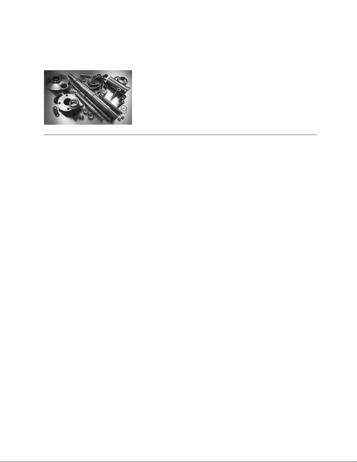
PARTS
The use of genuine Goulds parts will provide the safest and
most reliable operation of your pump. ITT Goulds Pumps ISO
certification and quality control procedures ensure the parts are
manufactured to the highest quality and safety levels.
Please contact your local Goulds representative for details on
genuine Goulds parts.
S-8
Page 13
GENERAL INFORMATION
PUMP DESCRIPTION ................................................................................... 11
NAME PLATE INFORMATION ..................................................................... 12
RECEIVING THE PUMP ................................................................................ 13
INSTALLATION AND OPERATION CHECKLIST ........................................ 14
PUMP DESCRIPTION
The AF pump generates flow by the thrust or lift action
of rotating axial vanes of the impeller. Axial flow
pumps generate high flow rates and low head which
are ideal for re-circulation, evaporator, and generator
cooling systems. The AF has an elbow that directs the
flow through the suction and out the discharge end of
the pump. It can be used in the top or end suction
configuration depending on the customer’s needs.
Refer to original factory documentation for the
arrangement of your pump. The model AF is based on
(6) power ends and (12) hydraulic pump sizes. The
first (3) power ends have ball bearings, the others
have taper and spherical roller bearings. Groupings
are as follows:
Power Inboard Outboard Pump
End
Bearing Bearing Size
1MXR Ball (2) Ang. Contact 6”, 8”, 10”
2MXR Ball (2) Ang. Contact 12”, 14”
3MXR Ball (2) Ang. Contact 16”, 18”
4MXR Sphrcl Roller Taper Roller 20”, 24”
5MXR Sphrcl Roller Taper Roller 700mm, 30”
6MXR Sphrcl Roller Taper Roller 36”
Elbow – The elbow is cast with 150# flat face suction
and discharge flanges, it comes with an opening in the
rear for a back-pullout. The back-pullout consists of
the bearing housing, shaft, and impeller. The elbow
has cast feet for mounting to a sub-base or it can be
mounted directly in the piping. It also comes with an
optional elbow liner.
Elbow or Casing Liner (Optional) – An optional liner
provides erosion and corrosion protection for longer
elbow or casing life. It may also come with a serrated
inside diameter for pumping stringy material.
Back-Pullout - The back-pullout is based on the (6)
power ends listed previously. It consists of a bearing
housing, bearings, stuffing box cover, locknuts,
lockwashers, labyrinth oil seals, shaft, shaft sleeve
(w/packing), oil slinger (20” ~36”), impeller, keys, shaft
washer, and a front and back foot.
Stuffing Box Cover – The cast stuffing box cover is
used to close the rear of the elbow and provide a
mounting surface for a mechanical seal or stuffing box
and gland. Inside it has a machined flat face with a (3)
or (4) bolt pattern to accept a stuffing box or standard
cartridge mechanical seal. When used with a
mechanical seal it has a cast in 5 deg. taper bore
opening to assist in ejecting particles from the seal
area. The cover comes with adjusting ears that allow
for centering on the shaft and also to center the
impeller in the elbow.
Mechanical Seal Adapter (Optional) – An optional
adapter is used when the mechanical seal requires a
restrictor bushing. The restrictor bushing is supplied
with the mechanical seal.
Optional
Packed Stuffing Box / Sleeve – The stuffing box is
cast and is separate from the elbow and stuffing box
cover. It comes with a replaceable wear sleeve that is
keyed to the shaft. Included are 5 rings of packing and
a lantern ring to seal the shaft area. Two flush ports
provide packing lubrication. A gland is used for
packing adjustment. The stuffing box can also be
modified to accept a mechanical seal if required.
Casing – A sacrificial wear casing is provided on the
700mm and 36” sizes. Adjusting lugs are used to
center the casing relative to the impeller. The casing
has 150# flanges for mounting to the elbow and comes
with an optional liner.
Impeller - The impeller is cast with (4) fixed vanes. It
is machined with internal steps for easy assembly onto
the shaft. It comes configured for 0 or +5 degree,
clockwise or counterclockwise rotation, and top or end
suction. The impeller is held in place with a shaft
washer and bolts. The 700mm and 36” impellers
come with cover plates and o-rings, to seal them from
the pumpage.
2
AF (6-36) IOM 11
Page 14
The seal prevents corrosion and allows for easy
impeller replacement. The impeller is dynamically
balanced (double plane) per ISO 1940 to a quality
grade G-16.
Shaft – The shaft is cantilevered into the pump elbow
to eliminate the need for internal bearings. It is
designed to have small deflections, high critical
speeds, and corrosion resistance. The shafts are
stepped for easy assembly with the impeller.
Bearings - The inboard radial bearing absorbs radial
loads and aligns the pump shaft. It is either a ball or
spherical roller bearing, depending on pump size. The
outboard thrust bearing absorbs thrust loads and
comes as either back-to-back angular contacts or a
single taper roller bearing, depending on pump size.
Lubrication is by flood oil or grease, depending on
customer requirements.
Oil Cooling (Optional) – An oil cooling option is
available on 12” and larger sizes. A coiled tube
mounted inside the bearing housing circulates water to
cool the oil bath. It is attached to the bottom of the
bearing housing by a removable bottom plate and
gasket. It is generally used when process
temperatures cause excessive heat build up in the
bearing housing and or bearings.
Configurations and Drives – Most AF pumps are Vbelt driven to allow for varying speeds. V-belts can be
configured for side by side, overhead, under-slung, or
vertical operation. The pumps can also be configured
with gear reducers and or jack shafts for direct connect
operation.
Maximum Sphere Size – The maximum solid size
that the AF can pass depends on the pump size. The
following are the maximum sphere sizes for each
pump:
Pump Sphere Pump Sphere
Size
Size Size Size
6” 1.5” 18” 4.5”
8” 2.0” 20” 5.0”
10” 2.5” 24” 6.0”
12” 3.0” 700mm 6.0”
14” 3.5” 30” 7.5”
16” 4.0” 36” 9.0”
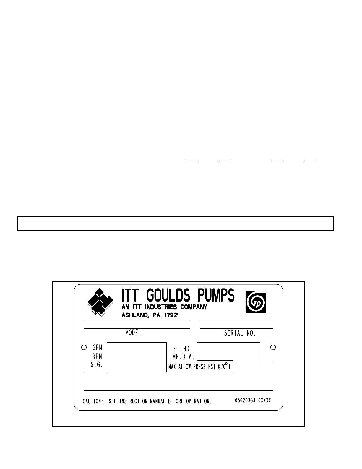
NAMEPLATE INFORMATION
Every Goulds pump has a nameplate that provides
information about the pump, including hydraulic
characteristics. The nameplate for the AF is located on
the bearing housing. Note the format of the pump
size: Discharge X Suction - Impeller Diameter in
inches (Example 20”X20”-20”, see Fig. 1). When
ordering spare parts you will need to identify pump
model, size, serial number, and the item number of
required parts. Information can be found in this
manual.
Fig. 1
12 AF (6-36) IOM
Page 15
RECEIVING THE PUMP
Inspect the pump as soon as it is received. Carefully
check that everything is in good order. Make notes of
damaged or missing items on the receipt and freight
bill. File any claims with the transportation company
as soon as possible.
STORAGE REQUIREMENTS
Short Term: (Less than 6 months) Goulds normal
packaging is via a skid. It is designed to protect the
pump during shipping only. Upon receipt, store in a
covered and dry location.
Long Term: (More than 6 months) Goulds long-term
packaging via crating. Preservative treatment of
bearings and machined surfaces is required. Rotate
the shaft several times every 3 months. Refer to driver
manufacturers instruction manual for their long-term
storage procedures. Store in a covered dry location.
Note: Long term storage treatment can be
purchased with initial pump order.
UNCRATING/DE-SKIDDING
Care should be taken when uncrating or de-skidding
pumps. If shipment is not delivered in good order, and
in accordance with the bill of lading, note the damage
or shortage on both the receipt and freight bill.
Make any claims to the transportation company
promptly. Instruction sheets as well as the instruction
book for the pump is included in the shipment - DO
NOT DISCARD.
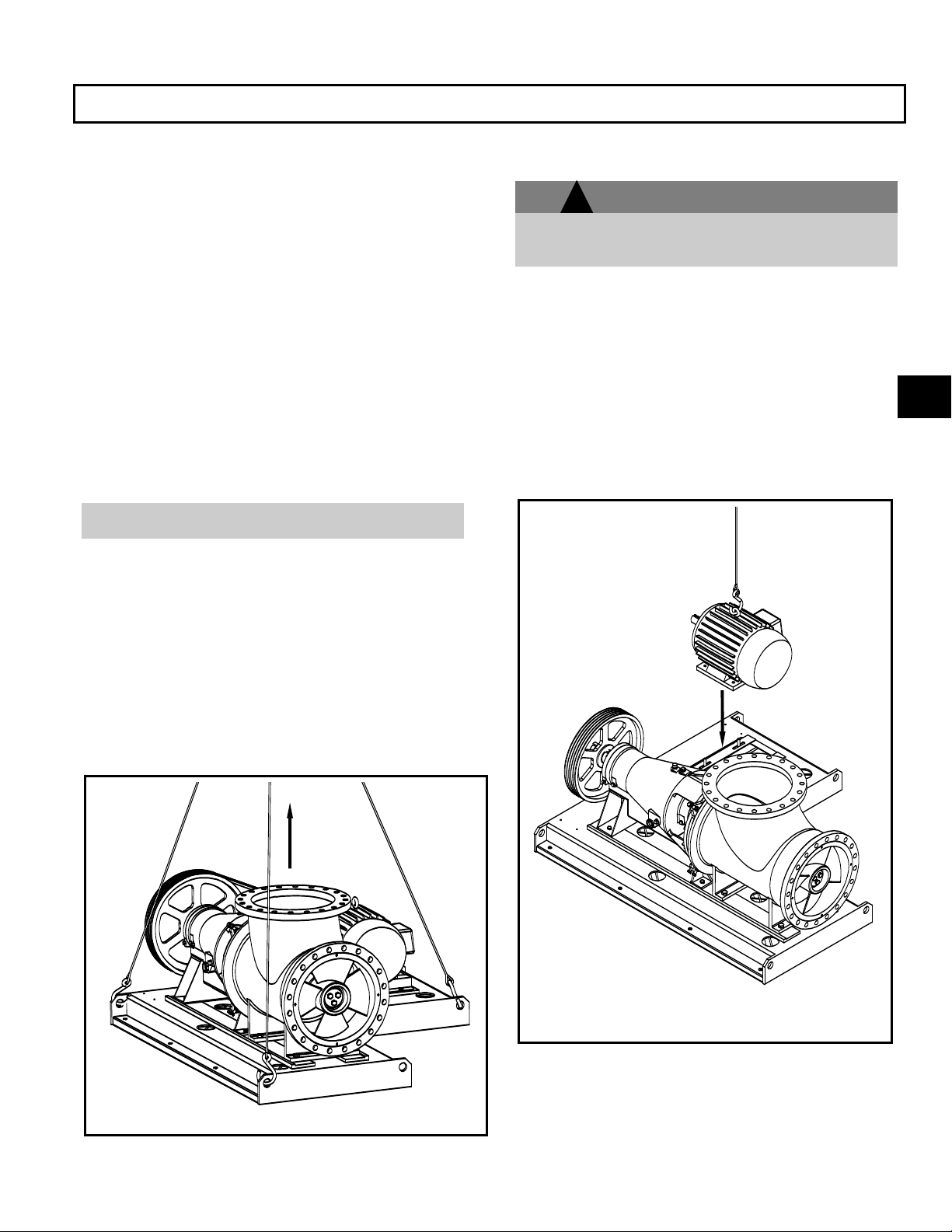
HANDLING
!
Pump and components are heavy. Failure to
properly lift and support equipment could result in
serious physical injury, or damage to pumps.
Use care when moving pumps. Lifting equipment
must be able to adequately support the entire
assembly. Lift assembled unit by the lifting holes
found in the sub-base. If the motor, sheaves, and
guard are in place be sure that the lifting cable or
chain does not come in contact with these
components. If necessary remove the guard or use a
spreader bar to prevent damage. In case the motor
ships separate use the eyebolts or lifting lugs found on
the motor to hoist it into place on the sub-base (Figs. 2
and 3 show examples of proper lifting techniques).
WARNING
2
FIG. 3
FIG. 2
AF (6-36) IOM 13
Page 16

g
INSTALLATION AND OPERATION CHECKLIST
Model AF
COMPLETE INITIAL DESCRIPTION PAGE NO.
Manual read and understood 1~69
Level foundation 15
Level subbase 15 ~ 19
Check motor rotation ---CW ---CCW 29
Component rough alignment complete 21 ~ 28
V-belt tension and alignment per drive mfgr. 21
Coupling alignment per cplg mfgr. 23
Piping installed and alignment rechecked 21,22,36
Mech. seal adjusted per mfgr. Mfgrs Mnl
Seal flush connected 33,34
Impeller alignment and clearance set Inch/Side 26 ~ 28
Pump shaft-free turnin
Bearing types and lubrication 12,32,39
V-belt or coupling guards installed 60,61
Motor electrical connections Mfgrs Mnl
32
14 AF (6-36) IOM
Page 17
INSTALLATION
PREPARATION FOR INSTALLATION ......................................................... 15
LOCATION/FOUNDATION ........................................................................... 15
SUB-BASE INSTALLATIONS ...................................................................... 16
PIPE HUNG INSTALLATIONS ..................................................................... 19
CONNECTION OF PIPING ............................................................................ 20
DRIVE ALIGNMENT PROCEDURES ........................................................... 21
IMPELLER ALIGNMENT .............................................................................. 28
ROTATION CHECK ...................................................................................... 29
PREPARATION FOR INSTALLATION
AF units are usually shipped completely assembled.
Check all bolts and nuts on the entire unit and make
sure they are securely tightened.
If necessary install and adjust drive components per
manufacturer’s recommendations
Equipment that will operate in a potentially
explosive environment must be installed in
accordance with the following instructions.
All equipment being installed must be
properly grounded to prevent unexpected
static electric discharge. If not, a static
electric discharge may occur when the pump
is drained and disassembled for
maintenance purposes.
3
LOCATION/FOUNDATION
AF pump shall be located in a clean, dry area free from
flooding. The area should provide adequate space for
operation, maintenance, inspection and repair,
considering complete disassembly and handling of
equipment. The pump should have a supply of clean
liquid for packing or mechanical seal lubrication. The
pump shall be positioned to provide the most efficient
pipeline system.
The AF pumps covered by these instructions may be
designed to hang in the piping system, furnished with
spring loaded sub-base bolts, or have a sub-base
designed to be anchor bolted and grouted to the
foundation.
The foundation must be substantial enough to absorb
any vibration and form a permanent, rigid support for the
pumping unit to the degree that there shall not be any
adverse movement or settling over a long period of time.
Foundations for anchor bolted and grouted sub-bases
are typically concrete with anchor bolts cast in to secure
the pump.
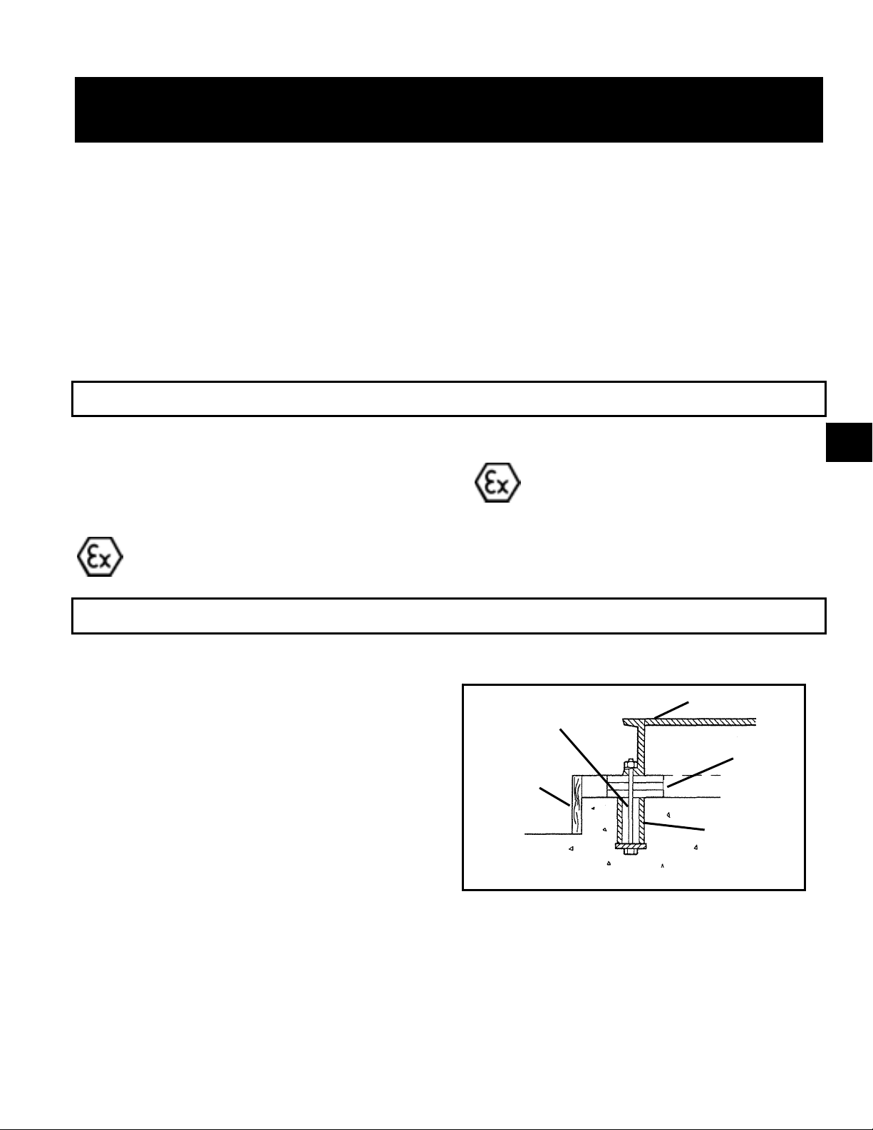
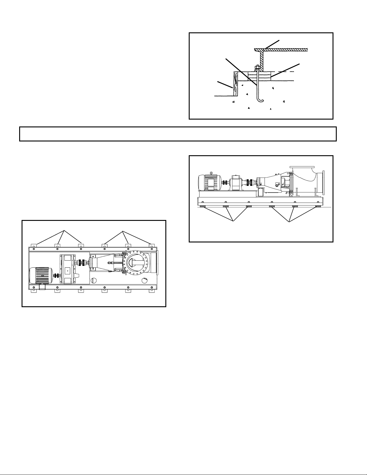
The most commonly used foundation bolts are the
sleeve-type (Fig 4) and J type (Fig. 5).
BASEPLATE
BOLT
SHIMS
DAM
SLEEVE
Fig. 4
Both designs permit movement for final bolt adjustment.
Anchor bolts should be located in the concrete by a
template dimensioned from the pump installation
drawing. The top of the sleeve-type bolt should be
temporarily sealed with waste material to prevent
concrete from entering during the concrete pouring
operation.
AF (6-36) IOM 15
Page 18
Foundation bolts are located according to the bolt hole
dimensions shown on the installation drawing. Bolt
size is based on hole size, they should be 1/8” to ¼”
under the sub-base hole size. For information on
spring mounted sub-bases, see the following section
under spring mounted bases.
SUB-BASE INSTALLATIONS
GROUTED BASE
When the unit is received with the pump and driver
mounted to the sub-base, it should be placed on the
foundation and the coupling halves or V-belts
disconnected (Fig. 6). The coupling should not be
reconnected until all realignment operations have been
completed. A recommended coupling alignment
procedure is included in the following sections.
SHIMS OR WEDGES
Fig. 6
1. The sub-base should be supported on rectangular
metal blocks or on metal wedges having a slight
taper. There should be support blocks or wedges
on both sides of each foundation bolt. A gap of
about 3/4" to 1-1/2' should be allowed between the
sub-base and the foundation for grouting (Fig. 7).
2. Adjust the metal supports or wedges until the
shafts of the pump and driver and sub-base are
level. Check the coupling faces, as well as the
suction and discharge flanges of the pump, for
horizontal and vertical position by means of a
level. Check also for any internal rubbing in the
pump. Correct, if necessary, by adjusting the
supports or wedges under the sub-base as
required. In most cases, factory alignment will be
regained by shimming under the sub-base alone.
BASEPLATE
J-BOLT
SHIMS
DAM
Fig. 5
SHIMS OR WEDGES
Fig. 7
Provisions must be made to support the discharge
piping independently from the pump to prevent
excessive loads and maintain pump-driver alignment.
3. The sub-base should be level to within .125 in. (3
mm) over the length of the base and .0875 in. (1.5
mm) over the width of the base. Bases anchored
with conventional foundation bolts use shims on
both sides of the anchor bolts to level the base.
The bolts which secure the pump sub-base to the
foundation should be 1/8” - ¼” less in diameter
than the holes in the sub-base (hole size is shown
on the certified installation drawing).
4. Clean outside areas of sub-base that will contact
grout. Do not use oil-based cleaners because
grout will not bond to it. Refer to grout
manufacturer's instructions.
5. Build a dam around foundation and thoroughly wet
the foundation (Fig. 8)
.
16 AF (6-36) IOM
Page 19
BASEPLATE
BOLT
GROUT
GROUT
DAM
FOUNDATION
Fig. 8
6. Pour grout through the grout holes in the sub-base,
up to level of dam. Remove air bubbles from grout
as it is poured by puddling, using a vibrator, or
pumping the grout into place. Non-shrink grout is
recommended.
7. Allow grout to set.
8. Fill remainder of sub-base with grout. Remove air
as before (Fig. 9)
BASEPLATE
BOLT
SPRING
POCKETS
is fastened to the sub-base. The stop nut is to limit the
vertical up motion of the sub-base in case part of the
load is removed from the pump unit when the system is
cold. The jam nut keeps the stop nut from turning during
normal operation when the sub-base has been pushed
down from the thermal expansion. The adjusting screw
holder is a bearing surface for the end of the adjusting
screw and serves to hold the end of the screw in a fixed
location.
Fig. 10
3
DAM
9. Allow grout to set at least 48 hours.
10. Tighten foundation bolts.
GROUT
FOUNDATION
Fig. 9
SPRING MOUNTED BASE
Fig. 10 shows a V-belt driven AF pump on a spring
mounted sub-base. Sub-bases supported by spring
pockets assure that the pump remains level, regardless
of vertical movement due to thermal pipe expansion
during operation.
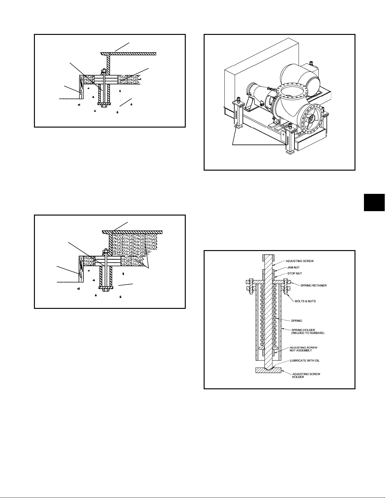
The following is a brief description of the spring pocket
components and their function (see Fig. 11). The
adjusting screw is used to compress or relax the spring.
Turning the screw causes the adjusting screw nut
assembly to move vertically and change the amount of
force the spring exerts against the spring retainer, which
Fig. 11
The adjusting screw was lubricated at the factory but
should be re-lubricated with heavy protective grease
during the pump installation. The springs and other
parts should be coated with an agent to protect the
surface from corrosion, and a heavy lubricant should be
applied to the adjusting screw holder pocket.
The following steps are used to set the springs and level
the sub-base:
AF (6-36) IOM 17
Page 20
1. Place blocks under the sub-base, near each spring
holder, and position the sub-base level on the
blocks. A small gap (approx. 1/16”) should exist
between the flange of the vertical pipe and the pump
elbow with the gasket in place (Fig. 12).
FLANGE
BOLTS
2. Install several flange bolts to help maintain
alignment of the flanges.
!
3. Position the adjusting screw holders, while the
adjusting screw end is seated in the hole, in the
direction of the horizontal thermal expansion. This
will allow the required horizontal motion without
having the adjusting screw nut assembly hit the
walls of the spring holder. Make sure there is
sufficient clearance between the adjusting screw
holder and the bottom of the sub-base for vertical
thermal expansion. This clearance is usually shown
on the pump installation drawing.
NOTE: Each spring carries a share of the unit load
but generally do not carry equal loads. Each holder
has a small "window” to check the spring coil
spacing, which is an indication of the relative load
on the spring. The installation drawing may indicate
the approximate number of turns required for each
WARNING
Do not tighten bolts.
1/16”
Fig. 12
spring location, especially if the unit uses more than
(4) springs. If necessary refer to table 1 for spring
rate information.
4. Turn the adjusting screws until the bottom of the
sub-base just clears each block. Next adjust each
screw evenly until the pump flange and gasket are
less than 1/32” away from the pipe flange. Careful
adjustment is necessary to keep the pump level and
obtain better weight distribution on the springs. After
the springs have been loaded and adjusted, the
base should be off the support blocks and level.
5. Check the alignment of the impeller and the pump
elbow. If necessary, correct the alignment by
adjusting the springs or by using shims.
NOTE: If the flange gap is over 1/32”, turn the
adjusting screws a uniform amount to close the gap.
For a gap of 1/32” or less, omit this step.
6. Tighten the vertical pipe flange bolts, recheck the
alignment and connect the horizontal pipe flange to
the elbow. The pump unit should be level and there
should not be any rubbing of the impeller in the
elbow when the shaft is turned by hand.
7. Run each stop nut down to make light contact with
the spring retainer. Lock in place by turning the jam
nut down tight against the stop nut.
8. Inspect each spring holder to check the gap
between the coils of the spring. There must be
enough total gap to accommodate the downward
thermal expansion of the system without having
them compressed solid.
NOTE: Pumps with oil lubrication should be checked
for being level while thermal expansion is taking
place. It may be necessary to add oil to the bearing
housing to provide the proper oil level to the higher
bearing. A line parallel with the sub-base deck
through the proper oil level line will show the correct
level at the highest end of the bearing housing. A
horizontal line back from that point will establish the
proper level mark on the sight gauge.
The system should be operated at normal temperature
before the adjusting screw holders are grouted in place.
Some customers operate their units with the adjusting
Spring Size Wire Size Spring Rate Adjusting Screw Size Load Change per Full Turn
1 .812” 1140 #/in. 1-1/2”-6 UNC 190 #
2 .750” 760 #/in. 1-1/2”-6 UNC 127 #
3 .532” 560 #/in. 1-1/2”-6 UNC 93 #
4 1.00” 1000 #/in. 2”-4-1/2 UNC 222 #
5 .375” 133 #/in. ¾”-10 UNC 13 #
Table 1
18 AF (6-36) IOM
Page 21
screw holders un-grouted.
If it becomes necessary to remove a spring assembly
from a spring pocket, for safety the following steps
should be strictly adhered to:
1. Make sure the spring is relaxed. If the spring cannot
be relaxed with the adjusting screw, the safest
method is to cut the coils using a torch.
2. Remove the bolts or cap screws, which fasten the
spring retainer to the holder and lift out the entire
assembly.
3. When the pump is connected to the system and a
spring is removed, there should be support under
the sub-base near the spring location until the spring
has been replaced and adjusted. Distortion of the
sub-base will affect the pump alignment,
4. and the weight of the components is more likely to
cause distortion when the pump is connected to the
rigid pipe system.
5. If a spring is replaced while the system is hot, the
stop nut should not be set until the system is cold.
6. The springs must be allowed to push the base back
to its cold position.
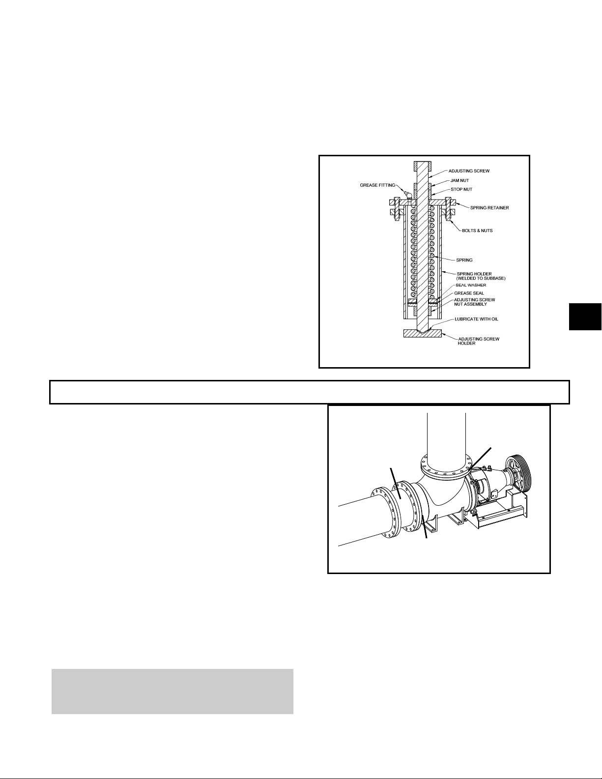
An optional grease filled spring pocket is shown in figure
13. The difference between the standard pocket and the
grease filled pocket is the addition of a grease fitting and
grease seal. Adjustment and setting of the grease filled
pocket are identical.
3
PIPE HUNG INSTALLATIONS
PIPE SUPPORT DESIGN REQUIREMENTS
1. Piping supports must meet Hydraulic Institute,
ASME/ANSI, DIN requirements, in conjunction
with standard construction practices.
2. Piping shall be stiff enough to prevent unwanted
pump vibrations.
3. Thermal expansion of the piping must be
accounted for by the piping/system designer.
4. Refer to the installation/dimensional drawing for
pump weights
5. Refer to pump flange load drawing for allowable
loads
6. Follow the power transmission manufacturer’s
recommendations for angular limits and thermal
movement of the pump relative to pump driver.
NOTE: Future access to the pump impeller and
shaft will require removal of a section of the
horizontal pipe. The piping shall have a spool
piece for this purpose (See Fig. 14).
Fig. 13
Upper
Spool
Piece
Lower
Flange
Flange
Fig. 14
INSTALLATION OF THE PUMP IN THE
PIPING
1. Connect the elbow upper flange to the vertical
pipe run and tighten the flange bolts.
2. Check the impeller clearance in the elbow/casing
to be sure it is well centered using the criteria that
the minimum gap at the vane O.D. is at least ½
the maximum gap. See the impeller check sheet
on pg. 28 of this IOM.
AF (6-36) IOM 19
Page 22
3. Connect the horizontal pipe or spool piece to the
elbow lower flange and tighten the flange bolts.
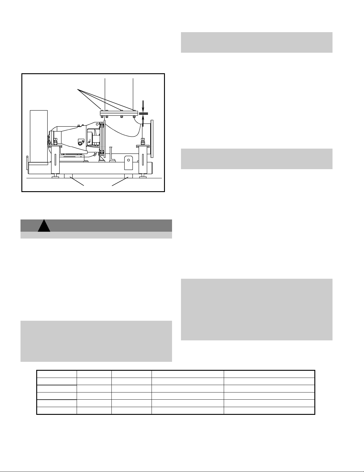
4. Check pump for level. Pump should be less than
1/2 degree (0.1”/ft) from horizontal so bearings are
not starved of oil (see Fig.15). Be sure thermal
expansion does not cause this angle to be
exceeded.
Must be less than
1/2 degree
Exaggerated
for effect
Fig. 15
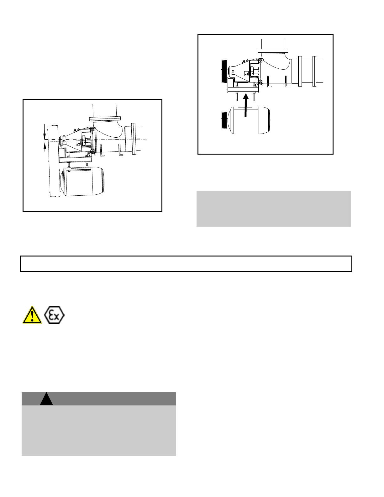
5. With the underslung arrangement install the motor
after the pump is connected to the piping. Be sure
motor shaft is parallel to the pump shaft in the
horizontal and vertical plane (see Fig.16).
Fig. 16
6. If pump unit is direct drive utilizing a drive shaft,
refer to the drive shaft manufacturer’s installation
manual for mounting instructions.
NOTE: PIPE FLANGES MUST BE PARALLEL WITH
THE PUMP FLANGE BEFORE THE BOLTS ARE
TIGHTENED. If the flanges are not parallel, forcing
them parallel by tightening the bolts will cause
excessive strain on the pump.
CONNECTION OF PIPING
GENERAL
Never draw piping into place by
forcing at the flanged connections of
the pump. This may impose
dangerous strains on the unit and
cause misalignment between pump
and driver. Pipe strain will adversely
effect the operation of the pump
resulting in physical injury and
damage to the equipment.
Guidelines for piping are given in the “Hydraulic
Institutes Standards” available from: Hydraulic
Institute, 30200 Detroit Road, Cleveland OH 441451967 and must be reviewed prior to pump installation.
!
Never draw piping into place by forcing at the
flanged connections of the pump. This may
impose dangerous strains on the unit and cause
misalignment between the pump and driver. Pipe
strain will adversely affect the operation of the
pump resulting in physical injury and damage to
the equipment.
WARNING
1. All piping must be supported independently of, and
line up with the pump flanges.
2. Piping runs should be as short as possible to
minimize friction losses.
3. DO NOT connect piping to the pump until the
pump and driver hold-down bolts have been
tightened.
4. It is suggested that expansion loops or joints be
properly installed in suction and /or discharge lines
when handling liquids at elevated temperatures,
so linear expansion of piping will not draw pump
out of alignment.
5. The piping should be arranged to allow pump
flushing prior to removal of the unit on services
handling corrosive liquids.
6. Carefully clean all pipe parts, valves and fittings,
and pump branches prior to assembly.
20 AF (6-36) IOM
Page 23

SUCTION AND DISCHARGE PIPING
!
NPSHA must always exceed NPSHR as shown on
Goulds performance curves received with order.
(Reference Hydraulic Institute for NPSH and pipe
friction values needed to evaluate suction piping
Properly installed suction piping is a necessity for
trouble-free pump operation. Suction piping should be
flushed BEFORE connection to the pump.
1. Use of elbows close to the pump suction flange
should be avoided. There should be a minimum of
2 pipe diameters of straight pipe between the
elbow and suction inlet. Where used, elbows
should be long radius.
2. Use suction pipe one or two sizes larger than the
pump suction, with a reducer at the suction flange.
Suction piping should never be of smaller diameter
than the pump suction.
3. To prevent suction cavitation, horizontal reducers
should be eccentric with the sloping side down
and concentric for vertical applications.
4. Pump must never be throttled on suction side.
5. Separate suction lines are recommended when
more than one pump is operating from the same
source of supply.
Suction lift conditions
1. Suction pipe must be free from air pockets.
2. Suction piping must slope upwards to pump.
3. All joints must be airtight.
Suction head/Flooded suction conditions
1. An isolation valve should be installed in the
suction line at least two pipe diameters from the
WARNING
suction to permit closing of the line for pump
inspection and maintenance.
2. Keep suction pipe free from air pockets.
3. Piping should be level or slope gradually
downward from the source of supply.
4. No portion of the piping should extend below
pump suction flange.
5. The size of entrance from supply should be one or
two sizes larger than the suction pipe.
6. The suction pipe must be adequately submerged
below the liquid surface to prevent vortices and air
entrainment at the supply.
Discharge piping
1. Isolation and check valves should be installed in
discharge line. Locate the check valve between
isolation valve and pump, this will permit
inspection of the check valve. The isolation valve
is required for priming, regulation of flow, and for
inspection and maintenance of pump. The check
valve prevents pump or seal damage due to
reverse flow through the pump when the driver is
turned off.
2. Increasers, if used, should be placed between
pump and check valves.
3. Cushioning devices should be used to protect the
pump from surges and water hammer if quickclosing valves are installed in system.
Final Piping Check
1. Rotate shaft several times by hand to be sure that
there is no binding and all parts are free.
2. Check alignment, per the impeller alignment
procedure outlined on pg. 26 to determine
absence of pipe strain. If pipe strain exists,
correct piping.
3
DRIVE ALIGNMENT PROCEDURES
Alignment procedures must be followed to
prevent unintended contact of rotating parts.
Follow coupling manufacturer’s installation
and operation procedures.
AF (6-36) IOM 21
!
Before beginning any alignment procedure, make
sure driver power is locked out. Failure to lock out
driver power will result in serious physical injury.
Lock out driver power to prevent electric
shock, accidental start-up and physical
injury.
WARNING
Page 24

The AF pump comes with two drive variations, V-belt
and gear driven. Accurate alignment of both systems
is essential to long pump life and reduced pump
problems.
The points at which alignment are checked and
adjusted are:
Initial Alignment is done prior to operation
when the pump and the driver are at ambient
temperature.
Final Alignment is done after operation when
the pump and driver are at operating temperature.
Alignment is achieved by adding or removing shims
from under the feet of the driver and gearbox and
shifting equipment horizontally by adjusting bolts as
needed.
NOTE: Proper alignment is the responsibility of
the installer and user of the unit.
Trouble free operation can be accomplished by
following these procedures.
Initial Alignment (Cold Alignment)
Before Grouting Sub-base - To ensure alignment
can be attained. After Grouting Sub-base - To
ensure no changes have occurred during the mounting
process.
After Spring Setting – To ensure no changes
have occurred during the leveling process.
After Connecting Piping - To ensure pipe strains
have not altered alignment. If changes have occurred,
alter piping to remove pipe strains on pump flanges.
Final Alignment (Hot Alignment)
After First Run - To obtain correct alignment
when both pump and driver are at operating
temperature. Thereafter, alignment should be
checked periodically in accordance with plant
operating procedures.
NOTE: Alignment check must be made if process
temperature changes, piping changes, and or
pump service is performed.
V-BELT DRIVE (SHEAVES)
Well designed and properly installed V-belt drives are
capable of running for years. AF pumps come in
several different belt drive configurations i.e. side by
side, overhead, underslung or “Z” mount. Installation
and alignment procedures are similar for all
configurations. Remove the guard or guards by
referring to the assembly/disassembly instructions.
There are a few items that should be checked during
installation and alignment.
Sheave Alignment - Alignment must be maintained
for full power transmission, minimum vibration, and
long drive life. A dial indicator can be used to check
runout on the periphery and face of each sheave. A
straight edge can be used to check parallel and
angular alignment of the pump and drive sheaves, see
Fig. 17.
1. Belt Installation - When installing new belts,
shorten center distance between sheaves so that
belts can be placed on the sheave without the use
of force. Never 'roll' or "Pry" the belts into place,
as this could damage the belt cords.
2. Check Belt Fit - Regardless of the belt section
used, the belt should never be allowed to bottom
in the groove. This will cause the belts to lose
their wedging action and slippage can occur.
Sheaves or belts that permit such a condition to
occur should be changed.
3. Maintain Proper Belt Tension - Proper tension is
essential for long belt life. Improper tension could
cause belt fatigue and/or hot bearings.
4. Impeller Alignment after Belt Tensioning – If
the impeller was aligned prior to belt tensioning a
check should be made to determine that it is still
centered. An off center impeller may rub and
cause unnecessary pump damage. Belt Tension
will usually cause impeller misalignment opposite
the motor. Be sure to align or re-align in
accordance with the Impeller Alignment section
page 26.
Fig. 17
22 AF (6-36) IOM
Page 25

The general method of tensioning belts is given
below, and should satisfy most drive requirements.
General Method:
STEP 1. Reduce the center distance so that the belts
may be placed over the sheaves and in the grooves
without forcing them over the sides of the grooves.
Arrange the belts so that both belt spans have a
proximately the same sag between the sheaves.
Apply tension to the belts by increasing the center
distance until the belts are snug, see Fig. 18.
Fig. 18
!
Do not operate the pump without the proper drive
guard in place. Failure to observe this warning
could result in personal injury to operating
personnel
STEP 2. Operate the drive a few minutes to seat the
belts in the sheave grooves. Observe the operation
of the drive under its highest load condition (usually
starting). A Slight bowing of the slack side of the
drive indicates proper tension. If the slack side
remains taut during the peak load, the drive is too
tight. Excessive bowing or slippage indicates
insufficient tension. If the belts squeal as the motor
begins operation or at some subsequent peak load,
they are not tight enough to deliver the torque
demanded by the drive machine. The drive should be
stopped and the belts tightened.
STEP 3. Check the tension on a new drive frequently
during the first day by observing the slack side span.
After a few days of operation the belts will seat
themselves in the sheave grooves and it may become
necessary to readjust so that the drive again shows a
slight bow in the slack side.
Other methods of determining proper belt tension can
be obtained from the drive manufacturer.
WARNING
5. Use Belt Guards - Belt guards protect personnel
from danger and the drive from contamination.
Inspect periodically to assure that belts do not rub
against guard.
6. Keep Belts Clean - Dirt and grease reduce belt
life. An occasional wiping with a dry cloth to
remove any build-up of a foreign material can
extend the life of the belt. Should oil or grease
splatter onto the belts, clean with soap and water.
Belt dressing affects performance only temporarily and
is never recommended. Maintaining a clean drive is a
better practice.
If any questions arise pertaining to the drive limitations,
consult the manufacturer.
GEAR DRIVE (COUPLINGS)
The coupling used in an ATEX classified
environment must be properly certified.
3
Remove the guard or guards by referring to the
assembly/disassembly instructions. Disconnect
motor/gearbox and the pump/gearbox coupling halves
before proceeding with the alignment. First, align the
pump/gearbox coupling then the motor/gearbox
coupling. Check both coupling connections for parallel
and angular alignment by either the Dial Indicator or
Straight-Edge Method outlined below.
Fig. 19
AF (6-36) IOM 23
Page 26

Good alignment is achieved when the dial indicator
readings, for both parallel and angular misalignment,
are .003" (.076mm) Total Indicated Reading (T.I.R.)
or less when the pump and driver are at operating
temperature (Final Alignment). Fig. 19 describes
what to look for.
Fig. 20
1. Mount two dial indicators off one half of the
coupling (X) so they contact the other coupling
half (Y) (Fig. 20).
2. Check setting of indicators by rotating coupling
half (X) to ensure indicators stay in contact with
coupling half (Y) but do not bottom out. Adjust
indicators accordingly.
MEASUREMENT
1. To ensure accuracy of indicator readings, always
rotate both coupling halves together so indicators
contact the same point on coupling half (Y). This
will eliminate any measurement problems due to
runout on coupling half (Y).
2. Take indicator measurements with hold-down
bolts tightened. Loosen hold down bolts prior to
making alignment corrections.
3. Take care not to damage indicators when moving
driver during alignment corrections.
Keep this instruction manual handy for reference.
Further information can be obtained by contacting the
Goulds Pumps, Ashland Operations, 500 E. Centre
St. Ashland, Pa 17921 or your local representative.
ALIGNMENT PROCEDURE
On gear driven AF pumps angular and parallel
misalignment are corrected in the vertical direction by
means of shims under the motor or gearbox mounting
feet, and in the horizontal direction by adjusting bolts
that slide the motor or gearbox in the proper direction.
After each adjustment, it is necessary to recheck the
alignment of the coupling halves. Adjustment in one
direction may disturb adjustments already made in
another direction. It should not be necessary to adjust
the pump in any way.
ANGULAR ALIGNMENT
Couplings are in angular alignment when indicator “A“
(Angular Indicator), Fig 20, does not vary by more than
.003” (.076mm) as measured at four points on the
coupling periphery 90 apart at operating temperature.
Outlined below are two acceptable methods to achieve
the desired alignment.
METHOD 1 - Dial Indicator Method
For steps 1 through 5 refer to Fig. 21.
1. Zero indicator “A” at position 1 of coupling half (Y).
Mark this position on both flanges.
2. Rotate both flanges 180 to position 3. Observe
needle and record reading.
3. Negative Reading - The coupling halves are
further apart at position 3 than position 1.
Positive Reading - The coupling halves are closer
at position 3 than position 1.
4. Correct any misalignment by shimming the under
the motor or gearbox feet to attain the proper
alignment.
Directions for viewing coupling
View from front end of pump
Fig. 21
24 AF (6-36) IOM
Page 27

When using positions 2 and 4 in steps 1-3, correct
any misalignment by sliding the motor back and forth
to attain the proper alignment.
5. Repeat steps 1-4 substituting position 2 for
position 1 and position 4 for position 3. Use the
same marks made on the coupling from position 1
and be sure to turn the coupling halves together.
METHOD 2 - Feeler Gauge Method
For the following steps refer to Fig. 21.
1. Insert a feeler gauge at position 1 at the periphery
of the couplings. Mark this position on both
flanges.
2. Record the largest gauge size that fits snugly
between the two flanges.
3. Rotate both flanges to position 3 - 180.
4. Insert a feeler gauge at the periphery of the
couplings at position 3
5. Record the largest gauge size that fits snugly
between the two flanges.
6. Calculate the difference between the readings at
positions 1 and 3. The difference should not be
greater than .003" (.076mm).
7. Correct any misalignment by shimming under the
motor or gearbox feet to attain the proper
alignment.
When using positions 2 and 4 in steps 1 - 6, correct
any misalignment by sliding the motor or gearbox
back and forth to attain the proper alignment.
8. Repeat steps 1-6 substituting positions 2 and 4
for position 1 and 3 respectively. Use the same
marks made on the coupling from position 1 and
be sure to turn the coupling halves together.
PARALLEL ALIGNMENT
The unit is in parallel alignment when indicator “P”
(Parallel Indicator) does not vary by more than .003”
(.076mm) as measured at four points on the coupling
periphery 90' apart at operating temperature. There
are two methods outlined below that are acceptable
to achieve the desired alignment.
NOTE: Equal amounts of shims must be added to
or removed from each driver foot. Otherwise the
vertical angular alignment will be affected.
METHOD I - Dial Indicator Method
For the following steps, refer to Fig. 21.
1. Zero the indicator “P” at position 1 of coupling half
(Y). Mark this position on both flanges.
2. Rotate both flanges 180 to position 3. Observe
needle and record reading.
3. Negative Reading - Coupling half (Y) is shifted
toward position 1.
If the value is greater than .003” (.076mm), correct the
misalignment by evenly (at equal amounts on both
sides) shimming the motor higher.
When using positions 2 and 4 in steps 1 - 2, correct any
misalignment by sliding the motor evenly toward
position 2.
Positive Reading - Coupling half (Y) is shifted
toward position 3.
If the value is greater than .003" (.076mm), correct the
misalignment by evenly (at equal amounts on both
sides) shimming the motor or gearbox lower.
When using positions 2 and 4 in steps 1 - 2, correct any
misalignment by sliding the motor or gearbox evenly
toward position 4.
4. Repeat steps 1-3 until indicator “P” reads .003"
(.076mm) or less.
5. Once the ideal alignment is reached, repeat steps
1-4 substituting position 2 for position 1 and
position 4 for position 3.
METHOD 2 - Straight-Edge Method
For the following steps refer to Fig. 21.
1. Place a straight edge across the two coupling
flanges at position 1 and mark the spot on both
flanges.
2. Adjust the motor or gearbox so that the straightedge rests evenly on both flanges (within .003"
.076mm).
3. Rotate both flanges 90 to positions 2 and repeat
steps one and two.
4. The unit will be in parallel alignment when the
straight edge rests evenly (within .003” .076mm) on
the coupling periphery at both positions along the
periphery.
3
AF (6-36) IOM 25
Page 28

NOTE: Care must be taken to have the straight
edge parallel to the axis of the shafts
COMPLETE ALIGNMENT
A unit is in complete alignment when both indicators
“A” (angular) and “P” (parallel) do not vary by more
than .003” (.076 mm) as measured at four points 90
apart.
Vertical Correction (Top-to-Bottom)
1. Zero indicators “A” and “P” at top dead center (12
o'clock) of coupling half (Y).
2. Rotate indicator to bottom dead center (6 o'clock).
Observe the needles and record the readings.
3. Make corrections as outlined previously.
Horizontal Correction (Side-to-Side)
1. Zero indicators “A” and “P” on the left side of
coupling half (Y), 90 from top dead center (9
o'clock).
2. Rotate indicators through, top dead center to the
right side, 180 from the start (3 o'clock), Observe
the needle, measure and record the reading.
3. Make corrections as outlined previously.
4. Recheck both vertical and horizontal readings to
ensure adjustment of one did not disturb the other.
Correct as necessary.
FACTORS THAT MAY DISTURB
ALIGNMENT
The unit should be checked periodically for alignment.
If the unit does not stay in line after being properly
installed, the following are possible causes:
1. Settling or spring of the foundation.
2. Wear of bearings.
3. Pipe strains distorting or shifting the machine.
4. Shifting of the sub-base due to heat created from
an adjacent heat source.
5. Shifting of the building structure due to variable
loading or other causes.
6. Loose nuts or bolts on the pump or driver
assembly.
NOTE: With experience, the installer will
understand the interaction between angular and
parallel and will make corrections appropriately.
IMPELLER ALIGNMENT
GENERAL
Improper impeller adjustment could cause
contact between the rotating and stationary
parts, resulting in a spark and heat
generation.
The impeller clearance setting procedure
must be followed. Improperly setting the
clearance or not following any of the proper
procedures can result in sparks, unexpected
heat generation and equipment damage.
The AF impeller has been aligned at the factory but
should be checked prior to pump operation. The
impeller requires several thousandths of and inch of
clearance to prevent rubbing due to the action of
hydraulic forces when the pump is operating. Many
corrosion-resistant alloys will gall and build up if
rubbing occurs, therefore, pumps using these alloys
need to be free from any rubbing.
Turn the shaft by hand, if the impeller rubs the inside
of the elbow or casing it must be realigned. The
following steps are used to align the impeller.
There are (2) types of impeller adjustment for the AF
pump. Type 1 has adjusting lugs on the stuffing box
cover, Type 2 has adjusting lugs on the elbow. Type 1
moves the back-pullout relative to the elbow. Type 2
moves the casing relative to the impeller to set the
clearance (see Figs. 22 and 23).
Note: Impeller rubbing is often caused by pipe
strain or belt tension. Pipe strain must be
eliminated prior to impeller alignment. The
impeller should aligned after proper belt
tensioning.
Clearance measurement - The alignment worksheet
on page 28 is used to align the impeller of the AF
pump. The measurement procedure is as follows:
26 AF (6-36) IOM
Page 29

Adj
Alig
t
Adj
Alig
t
Make sure the cap screws fastening the bearing
housing to the elbow, Type 1, or the casing to the
elbow, Type 2, are tight, so an accurate measuremen t
of the impeller clearances can be made prior to
adjustment.
Mark each blade 1, 2, 3 and 4 and then align the
impeller blades with the adjusting lugs on the stuffing
box cover (approx. 2, 4, 8, and 10 o’clock) Type 1, or
elbow (approx. 4, 8 o’clock) Type 2
Rotate the shaft and measure the gap between each
blade and the casing at all four clock positions
indicated on the worksheet. The value of interest is
the largest value of feeler gage thickness that will slide
easily the whole length of the vane tip.
Add the measurements for all positions together and
divide by the number of measurements. This will give
the average measurement.
Divide the average measurement by 2. This will give
the minimum clearance.
If any blade has a clearance in any position smaller
than the calculated minimum clearance the prop is not
sufficiently centered and should be adjusted.
Impeller Alignment – (Type 1)
1. Loosen the bolts that attach the bearing housing to
the elbow.
2. Use the adjusting bolts closest to the elbow to
adjust the impeller clearance, see Fig. 22. The (2)
upper adjusting bolts are used to raise and lower
the impeller. The upper and lower adjusting bolts
on either side are used to center the impeller left
to right in the elbow.
Box
Alignment
Impeller
Type 1
ustment
nmen
Fig. 22
3. Move the back pullout relative to the elbow until
the impeller is centered. At this point it is
recommended that the Impeller Alignment
Worksheet (on the following page) be filled out
and filed with the pump maintenance records for
future reference.
4. Tighten the bolts between the bearing housing and
elbow and re-check the clearance to be sure the
adjustments have centered the impeller. If the
impeller is centered the bearing housing may be
taper pinned to the elbow to maintain alignment.
Impeller Alignment – (Type 2)
1. Loosen the bolts that attach the casing to the
elbow.
2. Use the adjusting bolts attached to the elbow to
Not Used
Box
Alignment
Impeller
Type 2
ustment
adjust the impeller clearance, see Fig. 23. The (2)
adjusting bolts are used to raise and lower the
casing and shift the casing left to right relative to
the impeller.
3. Move the casing relative to the impeller until the
impeller is centered. At this point it is
recommended that the Impeller Alignment
Worksheet (on the following page) be filled out
and filed with the pump maintenance records for
future reference.
4. Tighten the bolts between the casing and the
elbow and re-check the clearance to be sure the
adjustments have centered the impeller. If the
impeller is centered the casing may be taper
pinned to the elbow to maintain alignment.
nmen
Fig. 23
3
AF (6-36) IOM 27
Page 30

28 AF (6-36) IOM
Page 31

ROTATION CHECK
Before the V-belts or couplings are installed, the motor
should be wired and the direction of rotation checked.
A rotation arrow is located on the bearing housing
(134C).
Serious damage could occur if the pump is run the
wrong direction.
When installing in a potentially explosive
environment, ensure that the motor is
properly certified.
3
AF (6-36) IOM 29
Page 32

THIS PAGE
INTENTIONALLY
LEFT BLANK
30 AF (6-36) IOM
Page 33

OPERATION
PREPARATION FOR OPERATION .............................................................. 31
STARTING THE PUMP ................................................................................. 33
OPERATION ................................................................................................. 34
SHUTDOWN .................................................................................................. 36
FINAL ALIGNMENT ...................................................................................... 36
PREPARATION FOR OPERATION
CHECKING ROTATION
When installing in a potentially explosive
environment, ensure that the motor is
properly certified.
Damage occurs from:
1. Increased vibration levels-affects bearings,
2. Increased radial loads Stresses on shaft and
3. Heat build up-Vaporization causing rotating
4. Cavitation-damage to internal surfaces of
Serious damage may result if pump is run in the
wrong direction.
Lock out power to prevent accidental start-up and
physical injury.
A check must be made to be sure motor rotation
coincides with the pump rotation direction. Depending
on your pump arrangement (V-belt or gear-drive) use
one of the following methods to check motor rotation.
Direct Connect
1. Lock out power to the driver.
stuffing box or seal chamber and mechanical
seal
bearings
parts to score or seize
pump
!
!
Serious damage may result if the pump is
run in the wrong direction.
CAUTION
WARNING
2. Remove the pump coupling guard.
3. Make sure the coupling halves are securely
fastened to shafts.
4. Unlock driver power.
5. Make sure everyone is clear. Jog the driver just
long enough to determine direction of rotation of
the output shaft of the gearbox. Rotation must
correspond to an arrow on bearing housing.
6. Lock out power to driver.
7. Replace the pump coupling guard.
The coupling guard used in an ATEX
classified environment must be constructed
from a non-sparking material.
V-BELT
1. Lock out power to the driver.
2. Remove the V-belt guard.
3. Make sure the sheaves are securely fastened to
shafts.
4. Unlock driver power.
5. Make sure everyone is clear. Jog the driver just
long enough to determine direction of rotation.
Rotation must correspond to an arrow on bearing
housing.
6. Lock out power to driver.
7. Replace the V-belt guard.
CHECK IMPELLER CLEARANCE
Check impeller clearance before installing the pump.
The impeller must not rub when the shaft is turned by
hand, therefore it is recommended that the Impeller
Alignment Worksheet (shown on pg. 28) is filled out
4
AF (6-36) IOM 31
Page 34

and filed with the pump maintenance records for future
reference.
CHECK FOR FREE TURNING
Before pump is started, rotate the pump by hand to be
sure it turns freely, and does not rub or bind
BEARING LUBRICATION
Before start up, the pump should be checked for proper
lubrication. AF pumps are flood-oil or grease
lubricated. Lubrication method is usually dependent on
the pump operating conditions. The following
paragraphs describe both methods of lubrication.
FLOOD OIL
Bearings must be lubricated properly in
order to prevent excess heat generation,
sparks and premature failure.
Oil lubricated bearings use an oil bath for lubrication.
Oil lubricated bearing assemblies are shipped without
oil. ADD OIL TO THE HOUSING UNTIL IT IS AT THE
CENTERLINE OF THE SIGHT GLASS. Oil must be
added to the bearing housing before starting. If the unit
has an external oil lube system, fill the bearing housing
and the reservoir to satisfy the system requirements.
Run the pump for 1 minute to fill the oil galleys and in
and around each bearing. Check the oil level indicator
and add oil accordingly. Monitor the oil level indicator
for the first 24 hours of operation and maintain fill level.
Change the oil after the first 200 hours of operation.
For normal operating conditions, change the oil at least
four (4) times a year. If the bearing assembly is
exposed to dirty or moist conditions, the oil should be
changed more often.
If the level of oil in the bearing housing (134C) is too
high, excessive heat may be generated due to
churning. If the level is too low, excessive heat may be
generated due to inadequate lubrication. A liquid level
switch connected to the oil sump can be used to warn
of a dangerous oil level condition.
Observe the oil level requirements shown on the
assembly drawing furnished with the pump. If
excessive heat is experienced within these levels,
consult the factory. Be sure that the shaft centerline is
horizontal through the bearing housing.
GREASE
Bearings are hand-packed at the factory and have
sufficient grease for at least 24 hours of operation after
startup. The bearings will run hotter than normal for
the first few hours until the grease is worked out of the
ball path and the bearings have “run- in”. Adding
more grease during this period may increase the
bearing temperature. After the first re-greasing, a
small amount of grease should be added at each
fitting every 500 hours of operation or 3 weeks of
continuous operation.
NORMAL BEARING TEMPERATURE
The running temperature for a bearing assembly
depends on many factors such as speed, bearing
loads, lubrication, ambient air temperatures, and
condition of bearings. Temperatures higher than the
human hand can tolerate are very satisfactory for
good bearing operation and should not cause any
alarm.
For a given speed and loading, the bearing housing
temperature will stabilize at some temperature,
usually below 200F., which will be the normal
temperature for the installation. Higher temperatures
than this normal temperature, without any change in
speed or loading can mean a lubrication difficulty or
the approach of bearing failure.
SHAFT SEALING
A packed stuffing box or mechanical seal is used to
seal the AF pump shaft. Both methods are described
below.
PACKED STUFFING BOX
Packed stuffing boxes are not allowed in an
ATEX classified environment.
The original equipment packing is a suitable grade for
the service intended. To pack the stuffing box use the
following procedure: (refer to Fig. 26, page 40)
1. Stuffing box and shaft sleeve must be clean and
free of grit.
2. Form packing over shaft or mandrel of same
diameter. Carefully cut to packing length.
Discard rings cut too short.
3. Pre-form each ring by coiling 1 -1 /2 turns.
4. To install packing rings, do not pull straight.
Expand the coil as a coil spring, see Fig 26 and
42 for the correct and incorrect method of
installing packing.
5. Expand the first coil as shown and insert into
stuffing box. Tamp packing to stuffing box
shoulder firmly with the gland. Note, where the
cut is positioned.
32 AF (6-36) IOM
Page 35

6. Install the second and third coil as required by
assembly drawing, staggering the cut 90 to 120.
7. Insert lantern ring into stuffing box, carefully noting
its proper position on the assembly drawing.
Failure to property locate the lantern ring will result
in insufficient packing lubrication. Packing and
shaft sleeve damage may result.
8. After packing and lantern ring are properly
installed, insert gland into stuffing box. Tighten
gland nuts finger tight only. The shaft should turn
freely.
9. Turn lubricant supply on, start pump, and adjust
the gland as described in Section III-E Stuffing Box
Adjustment.
10. Periodic maintenance is absolutely required for all
packed pumps. Normal shaft run-out should be
under .005” to avoid pounding of stuffing box
packing. With excessive shaft run-out, shaft
straightening or replacement is necessary.
MECHANICAL SEAL
The mechanical seal used in an ATEX
classified environment must be properly
certified.
The mechanical seal must always be
properly flushed. Failure to do so will result
in excess heat generation and seal failure.
Most mechanical seals are installed and adjusted at
the factory. A common seal type used on the AF
pump is the cartridge type. Cartridge seals are preset
at the seal manufacturer’s facility and require no field
settings. Due to size and design, some installed
mechanical seals are supplied with holding clips.
These clips keep the sealing faces apart to avoid
damage during transport. The clips must be removed
before the shaft is to be rotated. Pumps with retained
seal faces will be specifically marked and instructions
from the seal manufacturer for clip removal will be
provided. If the seal has been installed in the pump at
the Goulds factory, these clips have already been
removed. For other types of mechanical seals, refer
to the seal manufacturer’s instructions for installation
and setting.
Mechanical seals have a stationary and a rotating
sealing face. Commonly, these sealing rings are of
carbon and ceramic material, brittle in nature, and
easily damaged. As the sealing rings seat with the
operation of the pump, a compatible wear pattern
develops between the mating surfaces.
To disassemble the mechanical seal after the wear
pattern is established would necessitate the
replacement of the rotating element and stationary
sealing elements. Do not replace only one
component.
To insure the life and sealing characteristics of the
mechanical seal, lubricating liquid must be circulated
through the seal gland. Clear, grit-free liquid is
necessary. Goulds Pumps strongly recommends the
stocking of replacement sealing elements.
4
!
Do not make shaft adjustments on mechanical
seal installations without consulting seal
instructions and the pump assembly drawing.
Damage to the mechanical seal may result.
Dynamic seals are not allowed in an ATEX
classified environment.
WARNING
STARTING PUMP
PRIMING PUMP
Pumps that are not self-priming must be
fully primed at all times during operation.
1 All equipment and personal safety related devices
Start up Precautions
and controls must be installed and operating
properly.
AF (6-36) IOM 33
2 To prevent premature pump failure at initial start
up due to dirt or debris in the pipe system, ensure
the system has been adequately cleaned and
flushed.
3 Variable speed drivers should be brought to rated
speed as quickly as possible.
4 Variable speed drivers should not be adjusted or
checked for speed governor or overspeed trip
settings while coupled to the pump at initial start
up If settings have not been verified, uncouple the
Page 36

unit and refer to driver manufacturers instructions
for assistance.
5 Pumpage temperatures in excess of 200°F will
require warmup of pump prior to operation.
Circulate a small amount of pumpage throught the
pump until the casing temperature is within 100°F
of the pumpage temperature and evenly heated.
When starting pump, immediately observe
pressure gauges. If discharge pressure is
not quickly attained, stop driver, reprime and
attempt to restart
Never start the pump until it has been properly primed.
Check the pump impeller for submergence. The pump
must be full of liquid with specified submergence head
above the impeller. Do not run the pump dry, as this
might damage pump and seal components.
.
FLUSH FLOWS
Packing or mechanical seals are used to seal the
rotating shaft. Generally, a clear liquid such as water is
used to lubricate and cool the sealing elements. The
lubricating liquid pressure must be 10 -15 psi higher
than the pressure inside the elbow to prevent
pumpage from entering the sealing elements. The
lubricating liquid must be clean and free of grit. Shaft
scoring, packing destruction, and mechanical seal face
damage will result from contaminated lubricant.
The stuffing box may be on the suction or the
discharge side of the impeller, depending on the
direction of flow through the elbow ordered by the
customer. If the pressure inside the elbow is not
known, it should be measured with a pressure gauge
when the pump is operating.
The stuffing box is furnished with (2) N.P.T. holes for
piping the lubricating liquid. The lubricating liquid is
piped into one of them. Some users simply plug the
other hole. For additional cooling of the sealing
elements, an outlet pipe with a valve can be installed
to allow more liquid to flow through the stuffing box.
(Double mechanical seals have no leakage and
usually require a lubricant flow through the stuffing
box for cooling). The lubricating flow should be
regulated by the valve in the outlet pipe rather than by
throttling the flow in the supply pipe.
DRIVER
Start driver.
!
Immediately observe pressure gauges. If
discharge pressure is not quickly attained-stop
driver, check submergence level and attempt to
restart
CAUTION
SET DESIRED FLOW
If your system is equipped with a variable frequency
drive (VFD) or a variable speed V-belt drive, you may
this point want to set your speed for the desired flow.
!
Observe pump for vibration levels, bearing
temperature and excessive noise. If normal levels
are exceeded shut down and resolve.
CAUTION
OPERATION
GENERAL CONSIDERATIONS
Service temperature in an ATEX classified
environment is limited by the table in the
ATEX identification section.
Do not operate pump below
minimum rated flows or with suction
and/or discharge valve closed.
These conditions may create an explosive hazard due
to vaporization of pumpage and can quickly lead to
pump failure and physical injury.
Observe pump for vibration levels,
bearing temperature and excessive
noise. If normal levels are exceeded,
shut down and resolve.
recirculation.
Reference Hydraulic Institute for NPSH and pipe
frictionvalues needed to evaluate suction piping.
34 AF (6-36) IOM
Always operate the pump at or near
the rated conditions to prevent
damage resulting form cavitation or
Always vary capacity with regulating
valve in the discharge line. NEVER
throttle flow from the suction side.
Pump must never be throttled on
suction side.
NPSHa must always exceed NPSHr
as shown on Goulds performane
curves received with order.
Page 37

Most axial flow pumps are in evaporator circulation
service and since the evaporator performance and the
amount of product depends on the rate of liquid
circulation, care should be taken to maintain these
pumps in good operating condition.
When production drops off, it is usually due to lower
circulation rate. An approximation of this rate can be
made by several methods:
Temperature drop across the heat exchanger.
Visual inspection of flow in evaporator body.
Testing the circulating pump.
Items (1) and (2) above are covered by the evaporator
manufacturer.
While field conditions preclude absolute accuracy, a
check of pump performance will give reasonably close
results. This can be done by installing a mercury
manometer at pipe taps located at least-one pipe
diameter away from the suction and discharge flanges
of the pump. If-gauges are used, the pressure
differential times 2.31 divided by the specific gravity of
the slurry indicates the TDH against which the pump is
actually operating. If a manometer is used, then
inches of mercury times 1.0455 divided by specific
gravity equals TDH, providing water is in both legs of
the manometer and connecting lines.
Check the pump speed and determine flow rate (gpm)
from the pump curve. This curve will also give
efficiency from which the hp requirement can be
determined. A double check is to take motor ammeter
readings, convert to hp, figure 90% drive efficiency,
and use it against the pump curve to get GPM. This is
only an approximate check, as the hp curve on some
applications is rather flat, but is probably within 71/2%. It is important to take and record these readings
when the equipment is new, so that later readings can
be judged on a relative basis.
OPERATING AT REDUCED CAPACITY
!
DO NOT operate pump below minimum rated flows
or with a discharge valve closed. This condition
may create an explosive hazard due to
vaporization of pumpage and can quickly lead to
pump failure and physical injury.
WARNING
Driver may overload if the pumpage
specific gravity (density) is greater
than originally assumed, or the rated
flow rate is exceeded.
Listed below are some causes for circulation loss.
Keep in mind that operation at reduced capacities can
cause damage to the pump.
1. Increase in TDH against which pump operates
could be caused by:
a) Heat exchanger tubes partially plugged.
b) Too many heat exchanger tubes blanked off.
c) Improperly sized or partially plugged strainer.
2. Viscosity of slurry higher than it should be.
3. Pump speed low. V-belt drive may be slipping and
operating pump below design speed.
4. Pump throttled on suction side. Could be caused
by rubber lining pulling away from the suction pipe
and partially collapsing, by large solids dropping
into suction, or by improperly sized or-plugged
strainer in the suction pipe.
5. Pump partially plugged by large solid jammed
between two impeller blades. This will also cause
rough operation with excessive vibration.
6. Incorrect pump rotation. When changing motors
for any reason or after any electrical system
changes or modifications, always check motors for
correct direction of rotation.
7. Worn pump impeller and/or casing. On a new
pump, clearance between tip of impeller blade and
casing is carefully determined. As this clearance
increases, pump performance decrea ses.
It is not practical to predict performance at any given
clearance without running a test at this clearance. On
small pumps, this effect is magnified as the
percentage of impeller blade area lost from wear and
corrosion is higher.
Other pump conditions and possible causes are:
High Hp Demand
1. Increased head or viscosity
2. Pump speed too high
3. Specific-gravity of slurry higher-than normal
4. Packing gland pulled up too tight
5. Impeller rubbing in casing
4
AF (6-36) IOM 35
Page 38

NOISY OR ROUGH OPERATION
1. Throttled suction or plugging
2. Impeller rubbing in casing
Damage
Damage occurs from:
1. Increased vibration levels - Affects bearings,
stuffing box seal chamber, and mechanical seals.
2. Heat build up - Vaporization causing rotating parts
to score or seize.
3. Cavitation - Damage to internal surfaces of pump.
SHUTDOWN
1. Turn off power to pump motor.
2. In case of necessary maintenance or pump
inspection, lock driver to prevent accidental
rotation.
4. Loose impeller
5. Broken impeller blade
6. Bearings not properly lubricated
7. Bent shaft
8. Impeller out of balance.
Operating Under Freezing Conditions
Exposure to freezing conditions, while pump is idle,
could cause liquid to freeze and damage the pump.
Liquid inside pump should be drained.
!
When handling hazardous and/or toxic fluids, skin
and eye protection are required. If pump is being
drained, precautions must be taken to prevent
physical injury. Pumpage must be handled and
disposed of in conformance with applicable
environmental regulation.
WARNING
FINAL ALIGNMENT
1. Run the pump under actual conditions for a
sufficient length of time to bring the pump and
driver up to operating temperature.
2. Check alignment per alignment procedure outlined
earlier.
36 AF (6-36) IOM
Page 39

PREVENTATIVE MAINTENANCE
GENERAL COMMENTS ............................................................................... 37
MAINTENANCE SCHEDULE ........................................................................ 37
MAINTENANCE OF BEARINGS .................................................................. 38
MAINTENANCE OF SHAFT SEALS ............................................................ 40
PUMP TROUBLE SHOOTING ................................................................. 42,43
GENERAL COMMENTS
A routine maintenance program can extend the life of your pump. Well maintained
equipment will last longer and require fewer repairs. You should keep maintenance
records, this will help pinpoint causes of problems.
Condition Monitoring
For additional safety precautions, and where noted in this manual, condition monitoring devices should be
used.
This includes, but is not limited to:
For assistance in selecting the proper instrumentation and its use, please contact your ITT/Goulds representative.
Pressure gauges
Flow meters
Level indicators
Motor load readings
Temperature detectors
Bearing monitors
Leak detectors
PumpSmart control system
5
MAINTENANCE SCHEDULE
The preventive maintenance section must be
adhered to in order to keep the applicable
ATEX classification of the equipment.
Failure to follow these procedures will void the ATEX
classification for the equipment.
Routine Maintenance
Bearing lubrication
Seal monitoring
Vibration analysis
Discharge pressure
Temperature monitoring
AF (6-36) IOM 37
ROUTINE INSPECTIONS
Inspection intervals should be shortened
appropriately if the pumpage is abrasive
and/or corrosive, or if the environment is
classified as potentially explosive.
When handling hazardous and / or
toxic fluids, proper personal
protective equipment should be
worn. If pump is being drained,
precautions must be taken to prevent
physical injury. Pumpage must be
handled and disposed of in
conformance with applicable
environment regulations.
Page 40

Check for unusual noise, vibration and b earing
temperatures.
Inspect pump and piping for leaks
Check seal chamber/stuffing box leakage
Packing: Excessive leakage requires adjustment
or possible packing replacement. Refer to page
35 for packing gland adjustment.
Mechanical Seal: Should be no leakage.
3 MONTH INSPECTIONS
Check foundation and hold down bolts for
tightness.
MAINTENANCE OF BEARINGS
Operation of the unit without proper
lubrication will cause bearing failure,
and pump seizure.
Throughout this section on bearing
lubrication, different pumpage
temperatures are listed. If the
equipment is ATEX certified and the
listed temperature exceeds the
applicable value shown in Table 1
under ATEX identification, then that
temperature is not valid. Should this
situation occur, please consult with
your ITT/Goulds representative.
408D
319
Fig 24
If pump has been idle, check packing. Replace if
necessary.
If any rubbing noise has been noticed, re-align the
impeller.
Oil should be changed at least every 3 months
(2000 hrs) or more often if there are any adverse
atmospheric conditions that might contaminate or
break down the oil, or if it is cloudy or
contaminated as seen through the sight glass.
ANNUAL INSPECTIONS
Check pump capacity, pressure and power. If
pump performance does not satisfy your process
requirements, and process requirements have not
changed, pump should be disassembled,
inspected, and worn parts should be replaced,
otherwise, a system inspection should be done.
OIL LUBRICATED BEARINGS
Remove the fill plug (408D) and add oil until oil level is
at the center of the sight glass (319). Replace the fill
plug, see Fig. 24 and Table 2.
AXIAL FLOW PUMP
OIL VOLUME
Pump Size Quarts Litres
6” 1 .95
8” 1 .95
10” 1 .95
12” 4 3.80
14” 4 3.80
16” 8 7.60
18” 8 7.60
20” 19 18.10
24” 19 18.10
700mm 19 18.10
30” 19 18.10
36” 29 27.55
Table 2
Change the oil after 200 hours of new bearings,
thereafter every 2000 operating hours or 3 months
(whichever comes first).
Goulds recommends commercial oil such as
Mobil D.T.E.
Exxon Teresstic
38 AF (6-36) IOM
Page 41

or an equal quality grade oil. However, a good grade
of non-detergent oil of SAE#30 or #40 is usually
satisfactory. Consult a reputable supplier for
acceptable substitutes for the oils mentioned.
The viscosity of the oil should be 150 SSU at the
operating temperature to prevent accelerated bearing
wear. 150 F is the maximum temperature at which a
typical 30 wt. oil will supply the required viscosity.
For the best results, the minimum oil viscosity should
be maintained as follows:
Operating temp. below 150 F - SAE 30
Operating temp. below 160 F - SAE 40
Operating temp. below 180 F - SAE 50
An oil with a higher viscosity than required will increase
the bearing operating temperature because of the extra
viscous drag, but never to the point where the viscosity
becomes lower than required from the increased heat
generation. It is therefore better on bearings to use oil
that is too heavy rather than too light.
Change the oil after the first 200 hours of operation.
For normal operating conditions, change the oil at least
four (4) times a year. If the bearing assembly is
exposed to dirty or moist conditions, the oil should be
changed more often.
GREASE LUBRICATED BEARINGS
(6-18 inch sizes only)
The bearings are pre-lubricated at the factory. Re-
grease bearings every 500 operating hours or after
every 3 weeks of continuous operation.
Re-grease Procedure:
NOTE: When re-greasing there is danger of
impurities entering the bearing housing. The
grease container, the grease device, and fittings,
must be clean.
1. Wipe dirt from the grease fittings.
2. Fill both grease cavities through the grease fittings
(193A and 193B) found on the bearing housing
(134C). Use recommended grease and fill until
slight resistance is felt in the grease gun, see Fig.
25.
3. Wipe excess grease from fittings.
4. Ensure the bearing housing labyrinth seals are still
seated in place and have not been pushed from
their seats by grease pressure.
193A
193B
Fig. 25
NOTE: The bearing temperature usually rises after
re-greasing due to an excess supply of grease.
Temperature will return to normal after pump has
run and purged excess from the bearings, usually
two to four hours.
For most operating conditions a lithium complex soap
based grease of NLGI consistency No. 2 is
recommended. This grease is acceptable for bearing
temperatures of -15F to 350F (-26C to 177C). If
another brand is desired, it should be checked with
the supplier for being equivalent to the above.
LUBRICATING GREASE
REQUIREMENTS
Lubricant
Brand
NLGl Grade 2 3
Mobil Mobilux #2 ----Mobil Mobilith AW2 Mobilith AW3
Humble Lidok #2 -----
Exxon Unirex N2 Unirex N3
Shell Alvania #2 -----
Sunoco Multipurpose EP -----
SKF LGMT 2 LGMT 3
Texaco Regal Starfak #2 -----
Pumpage temp.
below 350F
(177C)
Table 3
Bearing temperatures are generally about 20F (18C)
higher than bearing housing outer surface
temperature.
Pumpage temp.
above 350F
(177C)
5
AF (6-36) IOM 39
Page 42

!
Never mix greases of different consistency (NLG 1
or 3 with NLG 2) or different thickener. For
example never mix a lithium base grease with
polyurea base grease.
CAUTION
MAINTENANCE OF SHAFT SEALS
MECHANICAL SEAL
When mechanical seals are furnished, a
manufacturer’s reference drawing is supplied with the
data package. This drawing should be kept for future
use when performing maintenance and adjusting the
seal. The seal drawing will also specify required flush
piping attachment points. The seal and all flush piping
must be checked and installed as needed prior to
starting the pump.
The life of a mechanical seal depends on various
factors such as cleanliness of the liquid handled and its
lubricating properties. Due to the diversity of operating
conditions it is, however, not possible to give definite
indications as to its life.
Pumpage temperatures above 350F (177C) should
be lubricated by a high temperature. Mineral oil
grease. Mineral oil greases should have oxidation
stabilizers and a consistency of NLGI 3.
6. Clean the stuffing box of any grit or build-up.
Clean the shaft sleeve prior to replacing the
packing. If the sleeve is damaged, now is the
time to replace it.
7. Install the packing and lantern ring in the reverse
order of removal, 2 rings of packing, lantern ring,
3 rings of packing, and the gland. Firmly seat
each ring. Stagger joints in each ring 90. Make
sure center of lantern ring lines up with flush tap
in the stuffing box.
8. Die formed packing rings are used when repacking a box. Care must be used during their
installation. To install packing, twist the ring
sideways just enough to get it around the shaft.
Do not attempt to pull rings straight out, see Fig.
26.
!
Never operate the pump without liquid supplied to
the mechanical seal. Running a mechanical seal
dry, even for a few seconds, can cause seal
damage and must be avoided. Physical injury can
occur if the mechanical seal fails.
WARNING
PACKED STUFFING BOX
If the axial flow pump has a stuffing box that seals the
rotating shaft the packing rings were installed at the
factory, but at some point during the life of the pump
they must be replaced. The following steps are used to
replace the packing:
1. Drain the system or isolate the pumpage from the
pump before replacing the packing.
2. Remove the nuts from the gland studs that hold the
gland in place.
3. Use a packing puller remove the first (3) rows of
packing from the box.
4. Use threaded rods or a packing puller to remove
the lantern ring from the box.
5. Use a packing puller remove the final (2) rings of
packing from the box.
PACKING RINGS
CORRECT
9. Insert the lantern ring with tapped extractor holes
facing outward from the box, be sure it is aligned
with the flush ports in the stuffing box, see Fig. 27.
10. Install the gland nuts finger tight. Then with the
lubricating supply on and the pump running,
gradually tighten the gland nuts one flat at a time,
while observing the leakage and stuffing box
temperature. Packing requires time to run-in.
11. Allow a minimum of ½ hour between adjustments.
If the leakage is reduced quickly, the packing will
overheat and may be destroyed. The shaft sleeve
may also become damaged. The normal leakage
INCORRECT
Fig. 26
40 AF (6-36) IOM
Page 43

for a properly adjusted stuffing box, depending on
the shaft size and speed, varies from a few drops
per second to a small trickle out of the gland.
pressure. The piping should be connected to the
stuffing box flush port inlet.
3. Under extreme temperature and pressure a pipe
should also be connected to the flush port outlet.
NOTE: Most packing requires lubrication. Failure
to lubricate packing may shorten the life of the
packing and pump.
4. An external drip pan (799G) drain is provided to
carry away normal gland leakage, see Fig. 28.
DRIP PAN
Fig. 27
LABYRINTH SEALS
Labyrinth seals have been provided to extend the life of
the bearings and prevent premature bearing housing
rebuild. They should occasionally be cleaned
externally and checked for wear, see Fig. 28.
CONNECTION OF SEALING LIQUID
If stuffing box pressure is above atmospheric pressure
and the pumpage is clean, normal gland leakage of 4060 drops per minute is usually sufficient to lubricate
and cool packing and sealing liquid is not required.
NOTE: Otherwise an external flush should be used
to lubricate and cool packing.
An external sealing liquid is required when:
1. Abrasive particles in the pumpage could score the
shaft sleeve.
2. Stuffing box pressure is below atmospheric
pressure due to pump running when suction
source is under vacuum. Under these conditions,
packing will not be cooled and lubricated and air
will be drawn into the pump. If an outside source
of clean compatible liquid is required, the pressure
should be 15-20 psi (1.1-1.4 kg/cm
2
) above suction
332, 333
799G
5
Fig. 28
AF (6-36) IOM 41
Page 44

A
A
A
Pump Troubleshooting
PROBLEM PROBABLE CAUSE REMEDY
No liquid delivered or
intermittent flow
Pump not producing rated flow
or head
Wear of internal wetted parts
is accelerated
Excessive leakage Stuffing box improperly packed Check packing and re-pack box
from stuffing box Worn mechanic al seal par ts Replace worn parts
Packing has short life Shaft/shaft sleeve worn Replace shaft or shaft sleeve if necessary
Pump not primed or prime lost, liquid level does not completely fill elbow Fill system piping completely so the impeller is submerged
Suction inlet clogged Remove obstructions from pump inlet
Impeller clogged with foreign material Back flush pump or manually clean impeller
Suction and /or discharge valve closed or clogged Open valves to remove shut-off condition
Wrong direction of rotation
Suction piping incorrect Replace or modify suction piping
Insufficient NPSH available Increase liquid level or lower pump
ir leak in suction line Test suction piping for leaks
Speed (rpm) too low New drive or gear box to obtain higher pump speed
Excess air entrapped in liquid Install vent in piping or eliminate air source
Impeller partly clogged Back flush pump or manually clean impeller
Insufficient suction head Fill system piping so the liquid level is above the pump impeller centerline
Pump not primed or prime lost, pump does not completely fill elbow Fill system piping completely so the impeller is submerged
Suction and/or discharge valve closed or clogged Open valves to remove partially blocked condition
Suction piping incorrect Replace or modify suction piping
Excessive air entrapped in liquid Install vent in piping or eliminate air source
Speed (rpm) too low New drive or gear box to obtain higher pump speed
Incorrect rotation Check motor wiring
Incorrect impeller or impeller diameter Check vane angles and/ or impeller clearances
System head too high Check system curve calculations, reduce system resistance
Instruments give erroneous readings Check and calibrate instruments, replace if necessary
Worn or broken impeller, bent vanes Inspect and replace if necessary
Pump assembled incorrectly Compare pump assembly to instruction manual
Insufficient NPSH available Increase liquid level or lower pump
Chemicals in liquid other than specified
Pump assembled incorrectly Compare pump assembly to instruction manual
Higher solids concentration than specified
Packing gland improperly adjusted Tighten gland nuts
Overheating mechanical seal Check lubrication and cooling lines
Shaft sleeve scored Re-machine or replace as required
Pump run off design point Check head and flow, AF’s should be run at <75% BEP > 115%
Packing gland not properly adjusted Replace packing and readjust gland as specified in the operating manual
Packing not properly installed Check head and flow, AF’s should be run at <75% BEP > 115%
Pump not assembled correctly Compare pump assembly to instruction manual
Change rotation to concur with direction indicated by the arrow on the
bearing housing
nalyze pumpage and correct or change pump wet end materials to suit
pumpage composition
nalyze pumpage and correct or change pump wet end materials to
harder composition
Table 4
42 AF (6-36) IOM
Page 45

A
A
A
A
A
A
PROBLEM PROBABLE CAUSE REMEDY
Bearings run hot and or fail on
a regular basis
Pump is noisy or vibrates at
higher than normal levels
High rate of mechanical seal
failure
Liquid heavier than expected Check specific gravity and viscosity
Motor requires excessive
power
Lubricant level Be sure the oil level is at center line of sight glass
Improper lubricant Check lubricant for suitability
Not lubricated enough Increase frequency of grease lubrication
Broken or bent impeller vanes Check impeller dimensions and vane layout
Excessive shaft misalignment Check shaft run-out and consult factory
Inadequate lubricant cooling Check pumpage temperature and add oil cooling system if necessary
xial thrust or radial load higher than bearing rating Calculate be ari ng life for make and model bearing
Improper coupling lubrication
Coupling out of balance
Suction pressure too high Check liquid levels and static suction pressure
Bearing incorrectly installed Check bearing orientation to sectional drawing
Impeller out of balance Check pump vibrations, if necessary rebalance impeller
Excessive shaft deflection Check shaft diameter, sag and deflection, consult factory
Pump run off design point Fill system piping completely so the impeller is submerged
Lubricant contamination Inspect oil or grease for contaminants
Piping not properly anchored Check to see if excessive pipe strain is being transferred to pump flanges
Pump and/or driver not secured to sub-base Check fasteners, if loose check alignment and re-tighten
Specific gravity higher than specified
Viscosity higher than specified
Pump assembled incorrectly Compare pump assembly to instruction manual
Partly clogged impeller causing
Imbalance
Broken or bent impeller or shaft Replace as required
Pump foundation not rigid or sub-base not completely secured Tighten hold down bolts on sub-base Check foundation rigidity
Impeller out of balance Check impeller balance
Motor not secure Check motor fasteners
Improper coupling lubrication
Bearing incorrectly installed Check bearing orientation to sectional drawing
Coupling out of balance
Pump operating speed too close to system’s natural frequency Change speed to be +/- 20% of the pumps natural frequency
Impeller partly clogged Back flush pump or manually clean impeller
Impeller clearances too tight Check impeller clearances adjust if necessary
Pump assembled incorrectly Compare pump assembly to instruction manual
Pump run off design point Check head and flow, AF’s should be run at <75% BEP > 115%
Excessive shaft deflection Check shaft diameter, sag and deflection, consult factory
Worn bearings Replace
Suction or discharge piping not anchored or properly supported
Suction and/or discharge valve closed or clogged Open valves to remove partially blocked condition
Excessive shaft misalignment Check shaft run-out and consult factory
Pump assembled incorrectly Compare pump assembly to instruction manual
Pump is cavitating, insufficient NPSH available System problem, increase liquid level or lower pump
Insufficient NPSH available Increase liquid level or lower pump
Excessive shaft misalignment Check shaft run-out and consult factory
Suction pressure too high Check liquid levels and static suction pressure
Bearing installed incorrectly Check bearing orientation to sectional drawing
Impeller out of balance Check pump vibrations, if necessary rebalance impeller
Overheating of seal faces Check flush flow with mfgr’s recommendation, increase if necessary
Excessive shaft deflection Check shaft diameter, sag and deflection, consult factory
Lack of seal flush to seal faces Check shaft diameter, sag and deflection, consult factory
Incorrect seal installation Check seal materials vs. pumpage to determine compatibility
Pump is run dry Fill system piping completely so the impeller is submerged
Pump run off design point Fill system piping completely so the impeller is submerged
Shaft/shaft sleeve worn Replace shaft or shaft sleeve if necessary
Coupling out of balance
Sub-base not installed correctly Compare pump sub-base installation to instruction manual
Bearing failing Replace if necessary
Piping not properly anchored Check to see if excessive pipe strain is being transferred to pump flanges
Pump and/or driver not secured to sub-base Check fasteners, if loose check alignment and re-tighten
Specific gravity higher than specified
Viscosity higher than specified
Pump assembled incorrectly Compare pump assembly to instruction manual
Head higher than rating. Reduced flow Check for fouling in the piping or obstruction in discharge
Incorrect rotation Jog motor and check rotation
Pump run off design point Check measured head and flow to specified head and flow
Stuffing box packing too tight Readjust packing. Replace if worn
Rotating parts binding, internal clearances too tight Check internal wearing parts for proper clearances
Pump Troubleshooting (Cont’d)
Check coupling lubrication schedule in manufacturers installation,
operation, maintenance manual
Check pump and drive component vibration levels, rebalance coupling if
necessary
nalyze pumpage and compare to specified gravity
nalyze pumpage and compare to specified viscosity
Back flush pump or manually clean impeller
Check coupling lubrication schedule in manufacturers installation,
operation, maintenance manual
Check pump and drive component vibration levels, rebalance coupling if
necessary
nchor per Hydraulic Institute Standards manual recommendation
Check pump and drive component vibration levels, rebalance coupling if
necessary
nalyze pumpage and compare to specified gravity
nalyze pumpage and compare to specified viscosity
Table 4 (Cont’d)
5
AF (6-36) IOM 43
Page 46

THIS PAGE
INTENTIONALLY
LEFT BLANK
44 AF (6-36) IOM
Page 47

!
DISASSEMBLY & RE-ASSEMBLY
REQUIRED TOOLS ....................................................................................... 45
DISASSEMBLY ............................................................................................. 45
INSPECTIONS .............................................................................................. 52
RE-ASSEMBLY ............................................................................................. 55
PARTS LIST & SECTIONAL DRAWINGS ............................................... 62-66
REQUIRED TOOLS
Safety glasses, leather gloves
11/16”, 7/8”, 1-1/16”, 1-1/4”, 1-5/8” wrenches or
sockets
Lifting slings or chains
Induction bearing heater
Brass drift punch
Spanner wrench
Allen wrenches
DISASSEMBLY
Disassembly procedures were written assuming the
entire pump and sub-base have been removed from the
piping. In most cases only the back pullout will need to
be removed for maintenance, the elbow can remain in
the piping.
!
Pump components can be heavy. Proper methods
of lifting must be employed to avoid physical injury
and or equipment damage.
!
The AF may handle hazardous and/or toxic fluids.
Skin and eye protection is required. Precautions
must be taken to prevent physical injury. Pumpage
must be handled and disposed of in conformance
with applicable Environmental Regulations.
WARNING
WARNING
Torque wrench with sockets
Micrometer
Cleaning Agents
Feeler gauges
Bearing puller
Crane or hoist
Lifting eyebolt (dependent on pump size)
NOTE: Before disassembling the pump for overhaul,
ensure all replacement parts are available.
!
Lock out driver power to prevent accidental start-up
and physical injury.
1. Shut all valves controlling flow “to and from” the
pump.
WARNING
WARNING
Operator must be aware of pumpage and safety
precautions to prevent physical injury.
2. Drain liquid from piping, flush the pump if necessary.
3. Disconnect all auxiliary piping and tubing.
6
AF (6-36) IOM 45
Page 48

4. If the pump is oil lubricated drain all oil from the
bearing housing before attempting to move the
pump.
5. Depending on the drive arrangement, either direct
connect or V-belt, use steps 6, 7 and 8, or 9, 10 and
11 respectively.
GUARD / DRIVE
Direct Connect Configuration
6. Remove the pump coupling guard screws and
guard (501), see Fig. 29.
COUPLING
COVERS
501
501
Fig. 29
7. Remove the fasteners that hold the coupling cover
halves together, remove each half and set it aside
for re-assembly. Do not remove the hubs from the
gear drive and pump shafts, see Fig. 30.
8. Remove the pump to sub-base bolts (372V) and
wrap lifting straps or chains around the bearing
housing (134C) and elbow (315A), see Fig. 31. Use
care when lifting the pump from the subbase. Be
sure all lifting devices are rated for the pump weight.
If any shims are found under the bearing housing
feet match mark and retain them for re-assembly.
Fig. 30
V-Belt Configuration
9. Remove the V-belt guard screws and the guard
cover (500) from guard base, see Fig. 32.
10. Relieve the belt tension by adjusting the slide base
toward the pump then remove the belts, see Fig. 33.
372V
372V
134C
315A
Fig. 31
46 AF (6-36) IOM
Page 49

500
500
500
Fig. 32
11. Remove the pump to sub-base bolts (372V) and
wrap lifting straps or chains around the bearing
housing (134C) and elbow (315A), see Fig. 34.
Using a crane, lift the pump vertically from the subbase. Be careful not to damage the pump by
striking any beams or walls that may be near the
pump. If any shims are found under the bearing
housing feet retain them for re-assembly later.
SHIFT
SLIDE
BASE
327V
134C
327V
Fig. 34
12. Depending on the drive type, remove the hub
fasteners that hold the coupling or pump sheave to
the shaft (122). Remove either a coupling half or
pump sheave and key (400). If the coupling half is
interference fit, heat may be necessary to remove it
from the shaft. Drive instructions are included with
the data package. Follow the manufacturer’s
instructions for coupling or sheave removal.
315A
6
REMOVE
BELTS
400
122
Fig. 33
Fig. 35
AF (6-36) IOM 47
Page 50

99O
BACK-PULLOUT / ELBOW OR ELBOW WITH
CASING / LINER (OPTION)
Elbow
13. Set the pump down on a smooth flat surface to
stabilize it for disassembly. Loosen the impeller
adjusting bolts (356A) so that they are clear of the
rear elbow flange. Remove the bolts (789L, 799O)
that attach the back-pullout (903A) to the elbow
(315A). With the elbow held in place, slide the backpullout from the elbow. Remove the face o-ring
(351) between the elbow and the back-pullout,
discard and order a replacement. Be sure to order
the correct o-ring material, see Fig. 36.
356A
351
315A
789L
799O
BACK-PULLOUT 903A
REAR
ELBOW
FLANGE
Elbow with Casing
14. The 700mm & 36” sizes come with a separate
casing. Remove the bolts (799C) and nuts (799D)
that secure the casing (100) to the elbow (315A).
Remove the casing and discard the mating o-ring or
gasket (351A). Loosen the four screws (356A).
Remove the bolts (789l & 799O) that secure the
back-pullout (903A) to the elbow and discard the oring (351), see Fig. 37.
356A
351
315A
Fig. 36
351A
100
Liner (option)
15. If the elbow (315A) or casing (100) has an optional
liner (103A) now is the time to remove it. Four
tapped holes in the liner flange are used with screws
to jack the liner from its seat. If the liner has been in
service this may require considerable effort due to
corrosion. If the liner is worn or deeply eroded,
order a replacement for re-assembly, see Fig. 38.
103A
315A
JACKING
SCREWS
Fig. 38
IMPELLER
Standard Impeller
16. Remove the bolts (198) that hold the shaft washer
(199) in place. Remove the shaft washer. To
remove the impeller (101), use a wooden mallet and
gently tap it to break it loose from the shaft (122).
Pull the impeller from the shaft, retain the shaft key
(178), see Fig. 39.
178
101
199
789L
7
BACK-PULLOUT 903A
799D
799C
Fig. 37
122
198
Fig.39
48 AF (6-36) IOM
Page 51

A
A
A
Sealed Impeller
17. 700mm and 36” sizes use an impeller cover (998E)
and O-rings to keep pumpage out of the impeller
cavity. The impeller cover must be removed first to
get to the shaft washer (199). Remove the bolts
(799B) and cover (998E) from the impeller (101).
Remove the cover o-ring (412T). Remove the bolts
(198) and shaft washer (199). To remove the
impeller (101), use a wooden mallet and gently tap it
to break it loose from the shaft (122). Pull the
impeller off the shaft, retain the shaft key (178), and
discard the impeller o-ring (412A). A pipe plug
(358I) located in the center of the cover is used to
test the impeller seal after re-assembly, do not
remove this plug, see Fig. 40.
178
199
412T
998E
122
412
101
198
358I
799B
Fig. 40
SEAL / STUFFING BOX COVER
Mechanical Seal w/ Optional Adapter
18. Be sure all gland flush tubing is disconnected. The
mechanical seal (383) is removed from the stuffing
cover (184) by removing the seal nuts (353) and
pulling the seal away from the stuffing box cover
(184). It is unnecessary to remove the gland studs
(355) unless they are damaged. If the seal includes
a restrictor bushing (496B) and optional adapter
(108B) remove these now. Remove and discard the
adapter gasket (211). Next remove the stuffing box
cover (184) by removing (2) screws (370C) that
secure the stuffing box cover (184) to the bearing
housing (134C). Remove the stuffing box cover
from the bearing housing. On larger pumps use a
sling or hook and chain to securely support the
weight of the stuffing box cover during removal.
Remove the adjusting bolts (356A) and all four
adjusting lugs (415). Be careful not to scuff or scar
the pump shaft (122) during removal, see. Fig. 41.
415
108B
383
122
370C
184
211
496B
353
134C
356
Fig. 41
Packed Box
19. With a packed box, the gland nuts (353), gland
(107), packing (106) and lantern ring (105) must be
removed before the stuffing box cover (184).
Remove all flush tubing. Remove the impeller
adjusting bolts (365A) and all (4) adjusting lugs
(415). Remove the two bolts (370C) that secure the
stuffing box cover (184) to the bearing housing
(134C) then remove the stuffing box cover. On
larger pumps use a sling or hook and chain to
support the weight of the stuffing box cover during
removal. Be careful not to scuff or scar the pump
shaft (122) or sleeve (126) during removal. Next
remove the stuffing box (220), bolts (799E) and
gasket (351W). Finally remove the set screw (469D)
and key (178D) that secure the shaft sleeve (126) to
the shaft (122). If the sleeve is immovable use a
brass drift to knock it from its seat. Be careful not to
mar or scratch the shaft during the process.
Remove and discard the o-rings (412D), see Fig. 42.
220
412D
351
799E
134C
356
370C
415
122
184
353
107
Fig. 42
178D
469D
126
355
6
105
106
AF (6-36) IOM 49
Page 52

A
DRIP PAN
20. Remove the street elbow (799G) from the drip pan
nipple, then the screws (799H) and washers (799I)
that secure the drip pan (179) to the bearing housing
(134C). Pull the drip pan from the bearing housing,
see Fig. 43.
799H
799I
799H
134C
Fig 43
BEARING HOUSING
21. Before removing the bearings carefully remove the
labyrinth seals from the outboard and inboard
positions (332, 333). Use a sharp edged tool or
screwdriver to remove them from the bearing
housing. Be careful not to damage the shaft (122)
or seat, see Fig. 44.
23. Using the eye bolt already threaded into the shaft,
pull the rotating assembly from the bearing housing,
see Fig . 46. Once the rotating assembly has been
removed place it on a set of wooden V-blocks for
bearing removal, see Fig.’s 47 and 48.
239
239B
788Z
370Y
799F
119C
331 or
412Y
134C
332
Fig. 45
ROTATING ELEMENT
333
134C
22. Lift the bearing housing up vertically by the drive end
using an eyebolt and chain. Be careful not to
damage the impeller end of the shaft. Place the
bearing housing on a bench or stand so that the
shaft protrudes down through it. At this time,
remove the screws (799F & 370Y) that secure the
front (239B) and rear feet (239A). Remove the
screws (788Z) that secure the thrust bearing retainer
(119C) to the bearing housing. Remove the retainer
and discard the gasket/shims (331) or o-ring (412Y),
see Fig. 45.
Fig. 44
1MXR-3MXR Configurations:
24. In order to remove the bearings first pry the tangs of
the lock-washer (382) from the lock-nut (136). Then,
using a spanner wrench remove the lock-nut (136)
and lockwasher (382). This thrust bearing
configuration consists of two back to back angular
contact bearings. Use a bearing puller to remove
both thrust bearings (112C). Finally, use a puller to
remove the inboard radial bearing (168C) from the
opposite end of the shaft. Be careful not to damage
the shaft, see Fig. 47.
50 AF (6-36) IOM
Page 53

X
168C
122
112C
Rotating
Element
382
Fig. 46
4MXR-6MXR Configurations:
25. In order to remove the bearings first pry the tangs of
the lock-washer (382) from the lock-nut (136). Use a
spanner wrench to remove the lock-nut (136) and
lockwasher (382). Slide off the keyed washer
(142B). This thrust bearing configuration is an
indirectly mounted taper roller bearing. Use a
bearing puller to remove the thrust bearing (112C).
Next, remove the thrust bearing collar (443X) and oil
wheel (248). The oil wheel has one to three set
screws (222N) that hold it to the shaft (122). The
collar and oil wheel must be removed prior to
removing the inboard bearing. Finally, use a puller
to remove the inboard radial bearing (168C) from the
drive end of the shaft. Be careful not to damage the
shaft, see Fig. 48.
136
Fig. 47
222N
112C
122
6
382
168C
248
443
136
142B
Fig. 48
AF (6-36) IOM 51
Page 54

A
A
COOLING COIL (OPTIONAL) / SIGHT GLASS
/ BREATHER AND PLUGS
Loosen and remove the screws (370F) that secure the
cover plate (113B) to the bearing housing (134C) and
discard the gasket. (360E). Remove the cover plate and
coil. Disconnect the connectors (972G and 972H) from
the cover plate and remove the cooling coil (984A). see
Fig. 49.
Finally, if necessary remove the breather (113A), pipe
plugs (408D, 408, 408A, 251C) and the sight glass
(319).
INSPECTIONS
Before re-assembly all AF wear parts should be
inspected using the following methods to insure the
pump will perform properly. Any part not meeting the
required criteria should be replaced.
NOTE: Clean parts in solvent to remove oil, or grease
or dirt. Protect machined surfaces against damage
during cleaning.
ELBOW / CASING / LINER (OPTIONAL)
The elbow and or casing (315A or 100) and liner
(103A) should be inspected for excessive wear or
pitting in the impeller and gasket areas. They should
be repaired or replaced if wear or corrosion exceeds
the following criteria, see Fig. 50.
1. Localized wear or grooving greater than 1/8 in.
(3.2mm) deep.
2. Pitting greater than 1/8 in. (3.2mm) deep.
361
972H
972G
360E
370F
984
408
408A
134C
251C
319
Fig. 49
3. Inspect case gasket seat surface for irregularities.
IMPELLER
1. Inspect impeller vanes for damage (101), Fig. 51.
Check the vane O.D. for erosion. Check the vane
surfaces, replace if grooved, worn or eroded
deeper than 3/16 in. (5.0 mm.) Excessive
impeller wear may cause a reduction in
performance.
2. Inspect the leading and trailing edges of the
vanes for pitting, erosion or corrosion damage
replace if grooved or worn deeper than 3/16 in.
(5.0 mm.)
3. Inspect the root (vane attach point at hub) of each
vane for cracks. Impeller vane failure can cause
unbalance in the rotating assembly that will lead
to catastrophic failure of the pump.
113
408D
3
1
2
1
3
2
2
1
3
Fig. 50
52 AF (6-36) IOM
Page 55

4. Inspect the keyway and stepped bores for signs of
pitting, wear or corrosion damage.
5. Check the O-ring groove and bolt holes for signs of
pitting or corrosion.
101
Fig. 51
SHAFT
1. Check the shaft (122) for straightness, wear,
corrosion, and radial run-out. Maximum run-out for
non-contact portions of the shaft is .003 in. max.,
see Fig. 52.
2. For all contacting surfaces such as bearing seats,
sleeve seats, and impeller mounting surfaces see
Table 5 on the following page.
1
2
2
SHAFT SLEEVE
1. The shaft sleeve (126) should be replaced if badly
grooved or worn. Localized wear or grooving
greater than 3/32 in. (2.4 mm) deep is cause for
replacement, see Fig. 53.
1
126
Fig. 53
MECHANICAL SEAL / RESTRICTOR
BUSHING
1. Refer to the mechanical seal (383) vendor’s
manual for inspection instructions.
2. The restrictor bushing, (496B) if necessary should
be replaced during re-assembly.
STUFFING BOX
1. Check the stuffing box (220) for localized wear or
grooving greater than 1/16 in. (1.6 mm) deep.
2. Pitting greater than 1/16 in. (3.2mm) deep.
3. Inspect stuffing box gasket seat surface for any
irregularities.
6
2
2
122
1
220
2
3
Fig. 52
1
2
Fig. 54
AF (6-36) IOM 53
Page 56

d
BEARING HOUSING
Inspect the bearing housing (134C) bores for signs of
scarring or galling from the outer race. Table 6 gives
the critical bore dimensions for the housings. The
bores should not be eggy and should be concentric,
see Fig. 55.
Outboard
Housing
Bore
134C
Inboard
Housing
Bore
Fig. 55
BEARINGS
The bearings (112C and 168C) should be inspecte d
for contamination and damage. The condition of the
bearing will provide useful information on operating
conditions in the bearing housing. Lubrication
condition and residue should be noted. Bearing
damage should be investigated to determine the
cause. If cause is not normal wear, it should be
corrected before the pump is returned to service.
DO NOT RE-USE BEARINGS
.
Labyrinth Seals and O-rings
Although the labyrinth seals (332, 333), O-rings (351,
351A, 351W, 412A, 412D, 412T, 412Y, 496D) and
gaskets (331, 351A, 351W, 211) may seem OK during
inspection and examination, DO NOT RE-USE
SEALS when rebuilding the pump. Replace them
while pump is disassembled.
Pump
Size
6
8
10
12
14
16
18
20
24
700mm
30
36
Inboard
Housing
Bore
3.5442
3.5433
4.7253
4.7244
5.9076
5.9055
7.8758
7.8740
9.8449
9.8431
11.0262
11.0244
Dimensions and Tolerances
Outboard
Housing
Bore
3.9379
3.9370
5.5128
5.5118
6.6950
6.6929
8.3780
8.3770
10.7530
10.7520
12.0030
12.0020
Critical Axial Flow
Inboard
Bearing
Seat
1.9690
1.9686
2.5597
2.5592
3.3472
3.3466
4.7263
4.7254
5.9071
5.9061
6.6945
6.6935
Outboard
Bearing
Seat
1.7722
1.7718
2.5597
2.5592
3.1502
3.1497
4.2531
4.2521
4.7534
4.7524
5.7525
5.7515
Table 5.
Mech.
Seal
Seat
1.750
1.748
2.500
2.498
3.250
3.248
5.250
5.248
6.250
6.248
7.000
6.998
Sleeve
Seat
1.687
1.685
2.437
2.435
3.248
3.247
5.188
5.186
6.187
6.186
6.9360
6.9335
Impeller End
st
1
Step 2
1.9995
1.9985
1.9895
1.9885
2.5935
2.5925
2.6245
2.6235
3.6240
3.6230
4.0000
3.9985
4.7180
4.7165
1.2495
1.2485
1.3745
1.3735
3.999
3.998
4.7490
4.7475
n
Step
2.0307
2.0297
1.9995
1.9985
2.6245
2.6235
2.6555
2.6545
3.6552
3.6542
4.0300
4.0290
54 AF (6-36) IOM
Page 57

A
RE-ASSEMBLY
Re-assembly of the AF is done opposite the order of
disassembly with a few exceptions. Be sure the parts
are clean and free of burrs and scratches. Every
assembly step should be double-checked to ensure
proper order and technique to prevent having to
partially disassemble the step you just finished.
COOLING COIL (OPTIONAL) / SIGHT
GLASS / BREATHER AND PLUGS
The optional cooling coil is installed by first fastening
two modified male connectors (972G) to the cooling
coil cover (113B). Insert the ends of the cooling coil
(984A) through the male connectors (972G) and screw
the female connector (972H) to the male compressing
the tubing in-between. Attach the cover plate (113B)
to the bearing housing (134C) using a new gasket
(360E) and the six screws (370F) w/ O-rings (370F)
see Fig. 56.
Install the breather (113A), pipe plugs (408, 408A,
408D, 251C) and sight glass (319) in the locations
shown in Fig. 56.
OUTER
THRUST
BEARING
112C
122
136
168C
382
INNER
THRUST
BEARING
Fig. 57
113B
972H
972G
360E
370F
496D
984A
408
408A
134C
113
408D
251C
319
Fig. 56
ROTATING ELEMENT
1MXR-3MXR Configurations:
1. Heat the inboard radial bearing (168C) to 225F
using an induction heater. Slide the bearing onto
the impeller end of the shaft (122), push it on until
it rests flush and square against the shaft
shoulder, see Fig. 57 and the sectional drawing at
the end of this section.
!
Use insulated gloves when using a bearing heater.
Bearings get hot and can cause physical injury.
2. Heat the inner thrust bearing (112C) to 225F. The
thrust bearings are mounted back-to-back, so
before placing the bearing on the shaft (122) be
sure that the large diameter face of the inner race
is facing the shaft shoulder.
3. Heat the outer thrust bearing (112C) to 225F.
Slide the bearing onto the shaft with the small
diameter of the inner race facing the inner thrust
bearing. Be sure it rests flush and square against
the inner thrust bearing.
4. Before the bearings cool install the bearing lockwasher (382) and lock nut (136). Tighten until
snug. Re-tighten the lock nut (136) several times
before the bearing cools completely. The tapered
end of the locknut (136) should face toward the
lock washer (382). Be sure that no clearance
exists between the outer and inner thrust bearing
(112C). With the nut secure align the slots with
the lock-washer tangs and bend the lock washer
tangs into the nut slots.
5. If the pump is grease lubricated pack the inboard
(168C) and outboard bearings (112C) with suitable
grease. Make sure the races are fully packed.
WARNING
6
AF (6-36) IOM 55
Page 58

X
4MXR-6MXR Configurations:
6. Heat the inboard radial bearing (168C) to 225F
using an induction heater. Slide the bearing onto
the drive end of the shaft (122) push it on until it
rests flush and square against the inboard
shoulder, see Fig. 58.
222N
112C
382
142B
136
122
443
168C
248
Fig. 58
(382). Tighten the whole unit until snug. Retighten the lock nut (136) several times before the
bearing cools completely. Be sure no clearance
exists between the inner race, collar (443X) and
shaft shoulder (122). With the locknut secure
align the slots with the tangs of the lock-washer
and bend the lock washer tangs into the nut slots.
11. If the pump is grease lubricated pack the inboard
(168C) and outboard bearings (112C) with suitable
grease. Make sure the races are fully packed.
BEARING HOUSING
12. Thread an eyebolt into the end of the shaft (122),
lift and lower the rotating element into the bearing
housing (134C), see Fig. 59. A collar similar to
that shown on pg. 69 should be used to prevent
misalignment of the inboard radial bearing.
122
Rotating
Element
!
Use insulated gloves when using a bearing heater.
Bearing will get hot and can cause physical injury.
7. Install the oil wheel (248) by sliding it onto the
shaft with the open end facing the inboard bearing
(168C). With the oil wheel up against its shoulder
install the set screws (222N) that hold it to the
shaft (122).
8. Heat may be applied to the thrust bearing collar
(443X) if necessary to install on the shaft. Install it
with the tapered end facing the oil wheel (248).
9. Heat the thrust bearing (112C) to 225F. Install
one row of roller bearings and the inner race on
the shaft (122). Be sure to slide the bearing on
the shaft until it is flush and square up against the
thrust bearing collar (443X).
10. While the thrust bearing is still hot install the outer
row of rollers and the outer race. Install the keyed
washer (142B), lock-washer (382) with its tang in
the groove on the shaft (122) and the lock nut
(136) with tapered end toward the lock washer
WARNING
134C
Fig. 59
26. Using screws (799F & 370Y), install the front
(239B) and rear feet (239A). Install the thrust
bearing retainer (119C), O-ring (412Y) (4MXR ~
6MXR) or gaskets (331) (1MXR~ 3MXR). See the
assembly drawing for proper shimming of
gasketed pumps. Install the screws (788Z) that
secure the thrust bearing retainer (119C) to the
bearing housing (134C), see Fig. 60.
56 AF (6-36) IOM
Page 59

A
DRIP PAN
14. Tilt the drip pan (179) so the attachment ears clear
the bearing housing (134C) flange and the nipple
protrudes through the cast hole in the bottom of
the bearing housing. Secure the drip pan to the
bearing housing ribs using the two screws (799H)
and washers (799I). Thread the street elbow
(799G) into nipple on the bottom of the drip pan,
see Fig. 62.
239
788Z
370Y
119C
331 or
412Y
134C
239B
799F
Fig. 60
13. Install the outboard and inboard labyrinth seals
(132) and (133). The drains should be located at
the bottom and face inward when mounted, see
Fig. 61.
132
133
134C
Fig. 61
799H
799I
179
799G
134C
Fig 62
SEAL / STUFFING BOX COVER
Packed Box
15. Place the sleeve key (178D) into the shaft (122)
key seat. Slip the O-ring (412D) into the shaft
sleeve (126) then slide the sleeve onto the shaft
until the keyways are lined up. Install the set
screw (469D) and tighten it to lock the sleeve in
place. Be careful not to mar or scratch the sleeve
or shaft during the process. Attach the stuffing
box (220) and gasket (351W) to the stuffing box
cover (184) using screws (799E). If removed reinstall the four studs (355). On larger pumps use
a sling or hook and chain to support the weight of
the stuffing box cover during installation. Mount
the stuffing box cover (184) to the register of the
bearing housing (134C). Be careful not to scuff or
scar the pump shaft (122) or sleeve (126) during
installation. Secure the stuffing box cover (184) to
the bearing housing (134C) using bolts (370C).
Pack the stuffing box initially with two rings of
packing (106) staggering the joints for each row.
Insert the lantern ring (105) being sure that the
lantern ring lines up with the flush ports. If the
lantern ring has taps for removal make sure they
face out of the box. Insert three more rings of
packing (106), gland (107), and gland nuts (353),
tighten the nuts only hand tight. Install all flush
tubing that may have been removed during
disassembly, see Fig. 63.
6
AF (6-36) IOM 57
Page 60

A
A
A
220
412D
351W
799E
134C
356
370C
415
122
184
353
105
106
107
Fig. 63
178D
469D
126
Mechanical Seal w/ Optional Adapter
16. The loose mechanical seal (383, 108) components
and gaskets (211) are slid onto the shaft (122) first
before the stuffing box cover (184) can be
installed. If the seal includes a restrictor bushing
(496B) an optional adapter (108B) will be included
with the pump. On large pumps use a sling or
hook and chain to securely support the weight of
the stuffing box cover during installation. Mount
the stuffing box cover on the bearing housing
(134C) register. Secure the stuffing box cover
(184) to the bearing housing (134C) using two
bolts (370C). Be careful not to scuff or mar the
pump shaft (122) during installation. Install the
four adjusting lugs (415) and impeller adjusting
bolts (356A). Use the upper adjusting screws
(356A) closest to the bearing housing to center the
stuffing box cover on the shaft. The seal
manufacturers instructions should be followed to
correctly install and align the mechanical seal.
Lastly, install the seal gland nuts (353) and secure
the seal to the stuffing box cover (184). Be sure
all gland quench or flush tubing is connected. see.
Fig. 64.
IMPELLER
Standard Impeller
17. Install the shaft key (178). Slide the impeller (101)
onto the shaft (122) and if necessary use a
wooden mallet to set it in place against the shaft
shoulder. Install the shaft washer (199) and
fasteners (198), tighten to lock the impeller (101)
in place, see Fig. 65.
178
122
Sealed Impeller
18. 700mm and 36” sizes use an impeller cover and
O-rings to keep pumpage out of the impeller
cavity. First, install the shaft key (178) on the
shaft. Using some silicone stick the impeller O-ring
(412A) to the back side of the impeller (101).
Slide the impeller (101) onto the shaft (122). If
necessary use a wooden mallet to set it in place
against the shaft shoulder. Install the shaft
washer (199) and bolts (198). Place the O-ring
(412T) on the cover and fasten the cover (998E) to
the impeller (101) using bolts (370M). Some
impeller covers have a pipe test plug (408H)
located on the face of the cover to test the cavity
seal after re-assembly, Re-install this plug (358I),
see Fig. 66.
198
101
199
Fig. 65
355
184
356
Fig. 64
178
199
412T
122
412
101
198
358I
370M
370C
415
108B
383
122
211
496B
353
134C
58 AF (6-36) IOM
998E
Fig. 66
Page 61

Back-Pullout / Elbow or Elbow with Casing /
Liner (option)
Elbow
13. Set the pump down on a smooth flat surface to
stabilize it for assembly. Loosen the impeller adjusting
bolts (356A) so that they are clear of the rear elbow
flange. Insert the O-ring (351) into the elbow groove
and hold in place with a small amount of grease. With
the elbow held in place, slide the back-pullout into the
elbow (315A). Install the bolts (789L and 799O) that
secure the back-pullout to the elbow (315A). Be sure
to use the correct O-ring material for the pumpage,
see Fig. 67.
356A
351
315A
789L
799O
O-ring or gasket (351A) between the casing (100) and
elbow (315A). Attach the casing (100) to the elbow
(315A) using the bolts (799C) and nuts (799D). With
casing (100) slightly loose adjust casing to center the
impeller., see Fig. 68.
Liner (option)
15. If the elbow (100) or casing (100) has an optional
liner (103A) now is the time to install it. The liner may
require some effort to install try using a wooden mallet
if resistance is noticed. The liner is sealed when it is
compressed against the pipe flange and requires no
gasket. If a replacement is necessary be sure to order
the correct material for the pumpage, see Fig. 69.
103A
BACK-PULLOUT
REAR
ELBOW
FLANGE
Elbow with Casing
14. The 700mm & 36” size pumps come with a
separate casing (100). Loosen the adjusting screws
(356A) so that they are clear of the elbow flange.
Insert O-ring (351) into the elbow groove and hold in
place with a small amount of grease. Be sure to use
the correct O-ring material for the pumpage. With the
elbow fixed, slide the back-pullout into the elbow
(315A) and install bolts (789L and 799O). Insert the
356A
351
315A
789L
799O
Back-pullout
799D
799C
Fig. 67
351A
100
Fig. 68
100
Fig. 69
DRIVE / GUARD
19. Insert the drive key (400) into the shaft (122)
keyseat. Depending on the drive type, install the
hub fasteners for a coupling or sheave to the shaft
(122). If you have a coupling halve that is
interference fit, you may need to heat it before
installing on the shaft (122). Drive instructions are
included with the data package. Follow the
manufacturer’s instructions for coupling or sheave
installation, see Fig. 70 on the following page.
20. Depending on the drive arrangement, either V-belt
or Direct Connect, use steps 21, 22 and 23, or 24,
25 and 26 respectively.
V-Belt Configuration
21. Using a crane, lift the pump into place on the sub-
base. Be careful not to damage the pump by
striking any beams or walls that may be near the
pump. If any shims were found under the bearing
housing feet during disassembly replace them at
this time. Install the pump to sub-base bolts
(500A) and remove the lifting straps or chains from
6
AF (6-36) IOM 59
Page 62

around the bearing housing (134) and elbow
(100), see Fig. 71.
400
122
Fig. 70
500A
500A
screws (502). Install the guard cover (500) using
screws (502), see Fig. 73.
24. Check impeller alignment and re-align if necessary
SHIFT
SLIDE
BASE
INSTALL
BELTS
Fig. 72
according to instructions on pg. 28 of section 3.
134
100
Fig. 71
22. Install V-belts and re-apply tension by adjusting
the slide base away from the pump. Adjust and
check the tension per the drive manufacturers
instructions, see Fig. 72.
23. Fasten the guard base (501) to the sub-base using
500
502
501
Fig. 73
Direct Connect Configuration
25. Using a crane, lift the pump into place on the subbase. Be careful not to damage the pump by
striking any beams or walls that may be near the
pump. If any shims were found under the bearing
housing feet during disassembly replace them at
60 AF (6-36) IOM
Page 63

!
this time. Install the pump to sub-base bolts
(500A) and remove the lifting straps or chains from
around the bearing housing (134) and elbow
(100), see Fig. 74.
500A
500A
134
100
Fig. 74
26. Align the gear box and pump coupling halves as
described on pg.’s 20 ~ 23 of section 3. If the
motor and gear box were moved during
disassembly re-align they must be re-aligned also.
27. Wrap the coupling cover around the coupling
halves and install the fasteners that hold the
coupling cover together, see Fig. 75.
COUPLING
COVER
28. Bolt the two halves of the coupling guard (500)
together and install over the coupling. Fasten the
guard to the sub-base using screws (502), see
Fig. 76.
29. Check impeller alignment and re-align if necessary
502
500
Fig. 76
according to instructions on pg. 28 of section 3.
30. Fill pump with proper lubricant. Refer to
preventative maintenance for requirements.
31. Connect all auxiliary piping and tubing.
32. Fill system piping so pump impeller is submerged,
flush the pump if necessary.
33. Open all valves controlling flow “to and from” the
pump.
34. Un-lock driver power and jog the pump motor to
be sure the pump rotates with no binding or rubs.
If all is proper, continue with pump start-up.
6
!
With power unlocked be careful so as to prevent
accidental start-up and physical injury.
WARNING
WARNING
Operator should be aware of pumpage and safety
precautions to prevent physical injury.
Fig. 75
AF (6-36) IOM 61
Page 64

AF SECTIONAL
(shown with optional restrictor bushing adapter)
Fig. 77
62 AF (6-36) IOM
Page 65

r
r
A
Parts List and Materials of
Item
Part Name
Construction
Standard Materials of
Construction
Cast Iron
304
316
Duplex SS
Alloy 20
Inconel
Monel
904L
Titanium
Nickel
100 Elbow 1002 1284 1245 1283 1247 1233 1119 1273 1601 1220
101 Impeller 1002 1284 1245 1283 1247 1233 1119 1273 1601 1220
105 Lantern ring Teflon
106 Packing Dependent on Pumpage
107 Gland 1002 1284 1245 1283 1247 1233 1119 1273 1601 1220
112C Outboard bearing Steel
113A Oil breather Steel
Thrust bearing
109
retainer
122 Shaft 2206 2228 2229 2230 3279 2369 2150 2266 2155 2156
126 Shaft Sleeve 1002 1284 1245 1283 1247 1233 1119 1273 1601 1220
134 Bearing housing 1000
136 Bearing locknut Steel
142B Keyed washer Steel
168C Inboard bearing Steel
178 Impeller key 2213 2228 2229 2230 2248 2369 2150 2266 2155 2156
178D Sleeve key 2213 2228 2229 2230 2248 2369 2150 2266 2155 2156
179 Drip pan 316 standard. Other options available.
184 Stuffing box cover 1002 1284 1245 1283 1247 1233 1119 1273 1601 1220
198 Impeller screw 2210 2228 2229 2230 2248 2369 2150 2266 2155 2156
199 Impeller lockplate 3201 2228 3211 2230 3270 2369 2150 2266 2155 2156
220 Stuffing Box 1002 1284 1245 1283 1247 1233 1119 1273 1601 1220
222A Set screw, Sleeve 2213 2228 2229 2230 2248 2369 2150 2266 2155 2156
Set screw, Oil
222B
wheel
239B Frame foot, inboard Steel
Frame foot,
239A
outboard
248 Oil wheel Iron
251C Plug, Oiler Steel
315A Elbow w/ Casing 1002 1284 1245 1283 1247 1233 1119 1273 1601 1220
315B Liner, Elbow 1002 1284 1245 1283 1247 1233 1119 1273 1601 1220
Laby seal,
332A
outboard
332B Laby seal, inboard Carbon Filled Teflon
351 Gasket, Stuff. Box 5302 5303 5309
Gasket,
351A
Elbow/Casing
353 Gland stud
355 Gland nuts
357G Nuts, Casing 2210 2228 2229 2230 2248 2369 2150 2266 2155 2156
356AAdjusting bolts Steel
358U Oil fill plug Steel
360WCover, Oil Cooling Steel
361 Gasket, Oil Cooling 5302
370F HHCS, Oil Cooling Steel
370G HHCS Casing 2210 2228 2229 2230 2248 2369 2150 2266 2155 2156
HHCS Bearing
370J
Housing / Elbow
370K HHCS Foot, Front Steel
HHCS SB Cover-
370H
Frame
HHCS SB Cover-
370L
Bearing Housing
5302 5303 5309
2210 2228 2229 2230 2248 2369 2150 2266 2155 2156
1000
Steel
Steel
Carbon Filled Teflon
2229
Steel
Steel
Parts List and Materials of
Construction
Part Name
Item
HHCS Impeller
370M
Cover
370Q Frame Foot, Rear Steel
370S End Cover Screws Steel
370U HHCS Adj. lug 2210 2228 2229 2230 2248 2369 2150 2266 2155 2156
370V HHCS Adj screw 2210 2228 2229 2230 2248 2369 2150 2266 2155 2156
370Y Frame foot screws Steel
Lock
382
washe
383 Mechanical Seal As specified
388Z Drip Pan Screws Stainless
400 Coupling Key Steel
408 Plug, Drain Steel
408A Sensor plugs Steel
408H Plug, Impeller 2210 2228 2229 2230 2248 2369 2150 2266 2155 2156
412F O-ring, Sleeve 5302 5303 5309
443X Spacer Steel
O-ring, Stuffing Box
496
Cover
496A O-ring End Cover BUNA-N
O-ring, Impeller
496B
Cap
O-ring, Impeller
496C
Nose
Gasket, Bearing
540C
Housing
555D Drip Pan Elbow Stainless Steel Standard. Other options available.
HHCS,
600Z
SBX/SBXCVR
787HAdjusting Ba
9727 Male Connector Steel
9728 Female Connector Steel
9841 Cooling Coil 2229
djusting Lug,
9879
Casing
9985 Impeller Cover 2210 2228 2229 2230 2248 2369 2150 2266 2155 2156
Cast Iron
2210 2228 2229 2230 2248 2369 2150 2266 2155 2156
5302 5303 5309
5302 5303 5309
5302 5303 5309
2210 2228 2229 2230 2248 2369 2150 2266 2155 2156
2210 2228 2229 2230 2248 2369 2150 2266 2155 2156
Standard Materials of
Construction
Duplex SS
304
Alloy 20
316
904L
Steel
5302
Steel
Inconel
Monel
Titanium
Nickel
6
AF (6-36) IOM 63
Page 66

126
351
AF OPTIONS
370F
Fig. 78
64 AF (6-36) IOM
Page 67

MXR BEARING
CONFIGURATIONS
1MXR – 3MXR 4MXR – 6MXR
540C
Fig. 79
AF (6-36) IOM 65
6
Page 68

IMPELLER
ALIGNMENT
BOX ALIGNMENT
(sizes 700mm and 36” only)
351A
251C
AF WITH SEPARATE CASING
Fig. 80
66 AF (6-36) IOM
Page 69

SPARE PARTS
When ordering spare parts, always state Goulds Serial No., and indicate part name and item
number from relevant sectional drawing. It is imperative for service reliability to have a sufficient
stock of readily available spares.
RECOMMENDED SPARE PARTS
Suggested Spare Parts
Elbow and or Casing (100, 315A)
Impeller (101)
Gaskets (211, 331, 351, 351A, 540C)
O-Rings (496, 496B, 496C)
Shaft (122)
Inboard Radial Bearing (168C)
Outboard Thrust Bearing or Bearings (112C)
Bearing Lockwasher (382)
Bearing Locknut (136)
Outboard Labyrinth Seal (332A)
Inboard Labyrinth Seal (332B)
Shaft Sleeve (126) (Optional)
Sleeve O-rings (412F) (Optional)
Stuffing Box Bushing (125Z) (Optional)
Lantern Ring (105) (Optional)
Stuffing Box Packing (106) (Optional)
Packing Gland (107) (Optional)
HOW TO ORDER PARTS
When ordering parts call
1-800-446-8537
or your local Goulds Representative
7
EMERGENCY SERVICE
Emergency parts service is available
24 hours a day, 365 days/year
Call 1-800-446-8537
AF (6-36) IOM 67
Page 70

THIS PAGE
INTENTIONALLY
LEFT BLANK
68 AF (6-36) IOM
Page 71

APPENDIX 1
BEARING ALIGNMENT COLLAR DETAIL
The bearing alignment collar is used to install the radial bearing on the 4MXR, 5MXR, and 6M XR bearing
configurations. It is recommended that you use this tool so as not to damage the radial bearing and or bearing
housing during rotating assembly installation.
BEARING ALIGNMENT COLLAR
Fig. 81
AF (6-36) IOM 69
8
Page 72

HOW TO ORDER
When ordering parts call
1-800-446-8537
or your local Goulds Representative
EMERGENCY SERVICE
Emergency parts service is available
24 hours/day, 365 days/year . . .
Call 1-800-446-8537
Visit our website at www.gouldspumps.com
Form No. IAF (6-36) 07/12
2012 Goulds Pumps, Incorporated
a subsidiary of ITT Corporation
 Loading...