

Page 1
Installation, Operation and Maintenance Instructions
Model 3996
Page 2

FOREWORD
This manual provides instructions for the Installation, Operation, and Maintenance of the Goulds Model 3996 pump. This manual covers
the standard product plus common options that are available. For special options, supplemental instructions are supplied. This manual
must be read and understood before installation and start-up.
The design, materials, and workmanship incorporated in the construction of Goulds pumps makes them capable of giving trouble-free
service. The life and satisfactory service of any mechanical unit, however, is enhanced and extended by correct application, proper
installation, periodic inspection, condition monitoring and careful maintenance. This instruction manual was prepared to assist operators in
understanding the construction and the correct methods of installing, operating, and maintaining these pumps.
Goulds shall not be liable for physical injury, damage or delays caused by a failure to observe the instructions for Installation,
Operation, and Maintenance contained in this manual.
Warranty is valid only when genuine Goulds parts are used.
Use of the equipment on a service other than stated in the order will nullify the warranty, unless written approval is obtained in advance
from Goulds Pumps.
Supervision by an authorized Goulds representative is recommended to assure proper installation.
Additional manuals can be obtained by contacting your local Goulds representative or by calling 1-800-446-8537.
THIS MANUAL EXPLAINS
Proper Installation
n
Start-up Procedures
n
Operation Procedures
n
Routine Maintenance
n
Pump Overhaul
n
Trouble Shooting
n
Ordering Spare or Repair Parts
n
3996 IOM 9/2010 5
Page 3

TABLE OF CONTENTS
9 SAFETY
13 GENERAL INFORMATION
17 INSTALLATION
21 OPERATION
27 PREVENTATIVE MAINTENANCE
33 DISASSEMBLY/REASSEMBLY
1
2
3
4
5
6
45 TROUBLESHOOTING
7
3996 IOM 9/2010 7
Page 4

IMPORTANT SAFETY NOTICE
To: Our Valued Customers
User safety is a major focus in the design of our products. Following the precautions outlined in this
manual will minimize your risk of injury.
ITT Goulds pumps will provide safe, trouble-free service when properly installed, maintained, and
operated.
Safe installation, operation, and maintenance of ITT Goulds Pumps equipment are an essential end user
responsibility. This Pump Safety Manual identifies specific safety risks that must be considered at all
times during product life. Understanding and adhering to these safety warnings is mandatory to ensure
personnel, property, and/or the environment will not be harmed. Adherence to these warnings alone,
however, is not sufficient — it is anticipated that the end user will also comply with industry and corporate
safety standards. Identifying and eliminating unsafe installation, operating and maintenance practices is
the responsibility of all individuals involved in the installation, operation, and maintenance of industrial
equipment.
Please take the time to review and understand the safe installation, operation, and maintenance guidelines
outlined in this Pump Safety Manual and the Instruction, Operation, and Maintenance (IOM) manual.
Current manuals are available at
your nearest Goulds Pumps sales representative.
www.gouldspumps.com/literature_ioms.html or by contacting
These manuals must be read and understood before installation and star t-up.
For additional information, contact your nearest Goulds Pumps sales representative or visit our Web site at
www.gouldspumps.com.
S-1
Page 5
SAFETY WARNINGS
Specific to pumping equipment, significant risks bear reinforcement above and beyond normal safety precautions.
WARNING
A pump is a pressure vessel with rotating parts that can be hazard o us. An y press ure vessel can explode,
rupture, or discharge its contents if sufficiently ove r press u r i zed causi n g deat h, personal injury, property
damage, and/or damage to the environment. All necessary measures must be taken to ensure over
pressurization does not occur.
WARNING
Operation of any pumping system with a blocked suction and discharge must be avoided in all cases.
Operation, even for a brief period under these conditions, can cause superheating of enclosed pumpage and
result in a violent explosion. All necessary measures must be taken by the end user to ensure this condition is
avoided.
WARNING
The pump may handle hazardous and/or toxic fluids. Care must be taken to identify the contents of the pump
and eliminate the possibility of exposure, particularly if hazardous and/or toxic. Potential hazards include, but
are not limited to, high temperature, flammable, acidic, caustic, explosive, and other risks.
WARNING
Pumping equipment Instruction, Operation, and Maintenance manuals clearly identify accepted methods for
disassembling pumping units. These methods must be adhered to. Specifically, applying heat to impellers
and/or impeller retaining devices to aid in their removal is strictly forbidden. Trapped liquid can rapidly
expand and result in a violent explosion and injury.
ITT Goulds Pumps will not accept responsibility for physical injury, damage, or delays caused by a failure to
observe the instructions for installation, operation, and maintenance contained in this Pump Safety Manual or the
current IOM available at www.gouldspumps.com/literature.
S-2
Page 6
SAFETY
DEFINITIONS
Throughout this manual the words WARNING, CAUTION, ELECTRICAL, and ATEX are used to indicate
where special operator attention is required.
Observe all Cautions and Warnings highlighted in this Pump Safety Manual and the IOM provided with
your equipment.
WARNING
Indicates a hazardous situation which, if not avoided, could result in death or serious injury.
Example:
Pump shall never be operated without coupling guard installed correctly.
CAUTION
Indicates a hazardous situation which, if not avoi ded, could result in minor or moderate injury.
Example: Throttling flow from the suction side may cause cavitation and pump damage.
ELECTRICAL HAZARD
Indicates the possibility of electrical risks if directions are not followed.
Example: Lock out driver power to prevent electric shock, accidental start-up, and physical injury.
When installed in potentially explosive atmospheres, the instructions that follow the Ex symbol must be
followed. Personal injury and/or equipment damage may occur if these instructions are not followed. If there
is any question regarding these requirements or if the equipment is to be modified, please contact an ITT
Goulds Pumps representative before proceeding.
Example:
parts, resulting in a spark and heat generation.
Improper impeller adjustment could cause contact between the rotating and stationary
S-3
Page 7
GENERAL PRECAUTIONS
WARNING
A pump is a pressure vessel with rotating parts that can be hazardous. Hazardous fluids may be contained by the
pump including high temperature, flammable, acidic, caustic, explosive, and other risks. Operators and
maintenance personnel must realize this and follow safety measures. Personal injuries will result if procedures
outlined in this manual are not followed. ITT Goulds Pumps will not accept responsibility for physical injury,
damage or delays caused by a failure to observe the instructions in this manual and the IOM provided with your
equipment.
WARNING
WARNING
WARNING
WARNING
WARNING
WARNING
General Precautions
NEVER APPLY HEAT TO REMOVE IMPELLER. The use of heat may cause an
explosion due to trapped fluid, resulting in severe physical injury and property damage.
NEVER use heat to disassemble pump due to risk of explosion from trapped liquid.
NEVER operate pump without coupling guard correctly installed.
NEVER run pump below recommended minimum flow when dry, or without prime.
ALWAYS lock out power to the driver befo re per fo rming pump maintenance.
NEVER operate pump without safety devices installed.
WARNING
WARNING
WARNING
WARNING
WARNING
NEVER operate pump with discharge valve closed.
NEVER operate pump with suction valve closed.
DO NOT change service application without approval of an authorized ITT Goulds
Pumps representative.
Safety Apparel:
Insulated work gloves when handling hot bearings or using bearing heater
Heavy work gloves when handling parts wit h shar p ed ges, especi al l y im pel l ers
Safety glasses (with side shields) for eye protection
Steel-toed shoes for foot protection when handling parts, heavy tools, etc.
Other personal protective equipment to protect against hazardous/toxic fluids
Receiving:
Assembled pumping units and their components are heavy. Failure to properly lift and
support equipment can result in serious physical injury and/or equipment d amage. Lif t
equipment only at specifically identified lifting points or as instructed in the current IOM.
Current manuals are available at
from your local ITT Goulds Pumps sales representative. Note: Lifting devices (eyebolts,
slings, spreaders, etc.) must be rated, selected, and used for the entire load being lifted.
www.gouldspumps.com/literature_ioms.html or
S-4
Page 8
WARNING
WARNING
CAUTION
General Precautions
Alignment:
Shaft alignment procedures must be followed to prevent catastrophic failure of drive
components or unintended contact of rotating parts. Follow coupling manufacturer’s
coupling installation and operation procedures.
Before beginning any alignment procedure, make sure driver power is locked out. Failure
to lock out driver power will result in serious physical injury.
Piping:
Never draw piping into place by forcing at the flanged connections of the pump. This may
impose dangerous strains on the unit and cause misalignment between pump and driver.
Pipe strain will adversely effect the operation of the pump resulting in physical injury and
damage to the equipment.
WARNING
WARNING
WARNING
WARNING
WARNING
WARNING
WARNING
WARNING
WARNING
Flanged Connections:
Use only fasteners of the proper size and material.
Replace all corroded fasteners.
Ensure all fasteners are properly tightened and there are no missing fasteners.
Startup and Operation:
When installing in a potentially explosive environment, please ensure that the motor is
properly certified.
Operating pump in reverse rotation may result in contact of metal parts, heat generation,
and breach of containment.
Lock out driver power to prevent accidental start-up and physical injury.
The impeller clearance setting procedure must be followed. Improperly setting the
clearance or not following any of the proper procedures can result in sparks, unexpected
heat generation and equipment damage.
If using a cartridge mechanical seal, the centering clips must be installed and set screws
loosened prior to setting impeller clearance. Failure to do so could result in sparks, heat
generation, and mechanical seal damage.
The coupling used in an ATEX classified environment must be properly certified and
must be constructed from a non-sparking material.
WARNING
WARNING
CAUTION
S-5
Never operate a pump without coupling guard properly installed. Personal injury will
occur if pump is run without coupling guard.
Make sure to properly lubricate the bearings. Failure to do so may result in excess heat
generation, sparks, and / or premature failure.
The mechanical seal used in an ATEX classified environment must be properly certified.
Prior to start up, ensure all points of potential leakage of process fluid to the work
environment are closed.
Page 9
CAUTION
WARNING
WARNING
WARNING
WARNING
WARNING
WARNING
WARNING
General Precautions
Never operate the pump without liquid supplied to mechanical seal. Running a mechanical
seal dry, even for a few seconds, can cause seal damage and must be avoided. Physical
injury can occur if mechanical seal fails.
Never attempt to replace packing until the driver is properly locked out and the coupling
spacer is removed.
Dynamic seals are not allowed in an ATEX classified environment.
DO NOT operate pump below minimum rated flows or with suction and/or discharge
valve closed. These conditions may create an explosive hazard due to vaporization of
pumpage and can quickly lead to pump failure and physical injury.
Ensure pump is isolated from system and pressure is relieved before disassembling pump,
removing plugs, opening vent or drain valves, or disconnecting piping.
Shutdown, Disassembly, and Reassembly:
Pump components can be heavy. Proper methods of lifting must be employed to avoid
physical injury and/or equipment damage. Steel toed shoes must be worn at all times.
The pump may handle hazardous and/or toxic fluids. Observe proper decontamination
procedures. Proper personal protective equipment should be worn. Precautions must be
taken to prevent physical injury. Pumpage must be handled and disposed of in
conformance with applicable environmental regulations.
Operator must be aware of pumpage and safety precautions to prevent physical injury.
WARNING
CAUTION
CAUTION
CAUTION
CAUTION
Lock out driver power to prevent accidental startup and physical injury.
Allow all system and pump components to cool before handling them to prevent physical
injury.
If pump is a Model NM3171, NM3196, 3198, 3298, V3298, SP3298, 4150, 4550, or
3107, there may be a risk of static electric discharge from plastic parts that are not
properly grounded. If pumped fluid is non-conductive, pump should be drained and
flushed with a conductive fluid under conditions that will not allow for a spark to be
released to the atmosphere.
Wear heavy work gloves when handling impellers as sharp edges may cause physical
injury.
Wear insulated gloves when using a bearing heater. Bearings will get hot and can cause
physical injury.
S-6
Page 10
ATEX CONSIDERATIONS and INTENDED USE
Special care must be taken in potentially explosive environments to ensure that the equipment is properly
maintained. This includes but is not limited to:
1. Monitoring the pump frame and liquid end temperature.
2. Maintaining proper bearing lubrication.
3. Ensuring that the pump is operated in the intended hydraulic range.
The ATEX conformance is only applicable when the pump unit is operated within its intended use. Operating,
installing or maintaining the pump unit in any way that is not covered in the Instruction, Operation, and
Maintenance manual (IOM) can cause serious personal injury or damage to the equipment. This includes any
modification to the equipment or use of parts not provided by ITT Goulds Pumps. If there is any question
regarding the intended use of the equipment, please contact an ITT Goulds represe ntative before proceeding.
Current IOMs are available at
Pumps Sales representative.
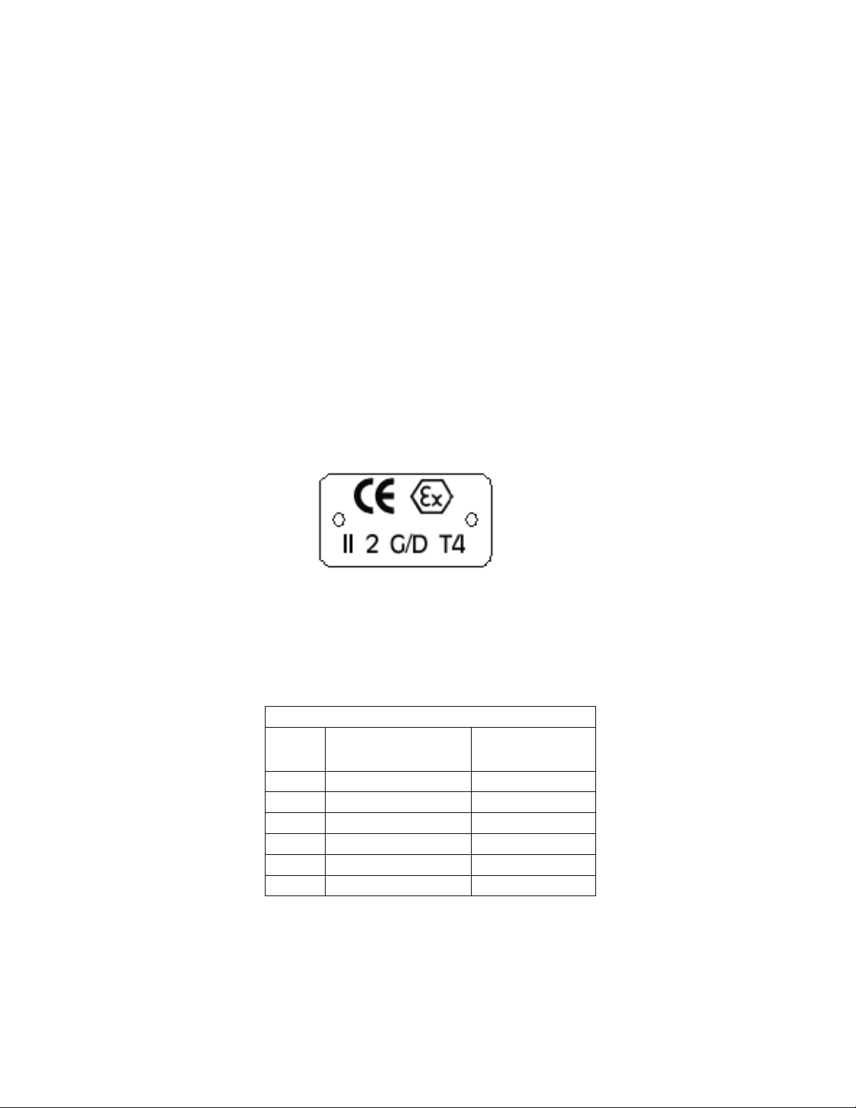
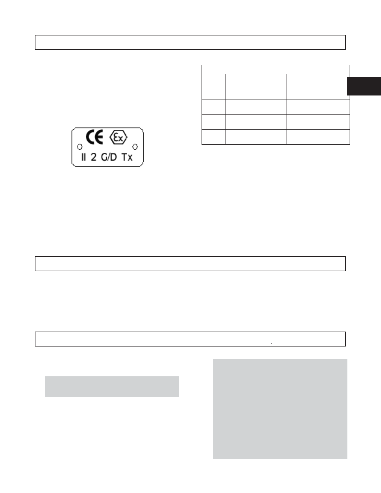
All pumping unit (pump, seal, coupling, motor and pump accessories) certified for use in an ATEX classified
environment, are identified by an ATEX tag secured to the pump or the baseplate on which it is mounted. A
typical tag would look like this:
www.gouldspumps.com/literature_ioms.html or from your local ITT Goulds
The CE and the Ex designate the ATEX compliance. The code directly below these symbols reads as follows:
II = Group 2
2 = Category 2
G/D = Gas and Dust present
T4 = Temperature class, can be T1 to T6 (see Table 1)
Table 1
Max permissible
surface temperature
Code
T1 842 (450) 700 (372)
T2 572 (300) 530 (277)
T3 392 (200) 350 (177)
T4 275 (135) 235 (113)
T5 212 (100) Option not available
T6 185 (85) Option not available
o
F (oC)
The code classification marked on the equipment must be in accordance with the specified area where the
equipment will be installed. If it is not, do not operate the equipment and contact your ITT Goulds Pumps sales
representative before proceeding.
Max permissible
liquid temperature
o
F (oC)
S-7
Page 11
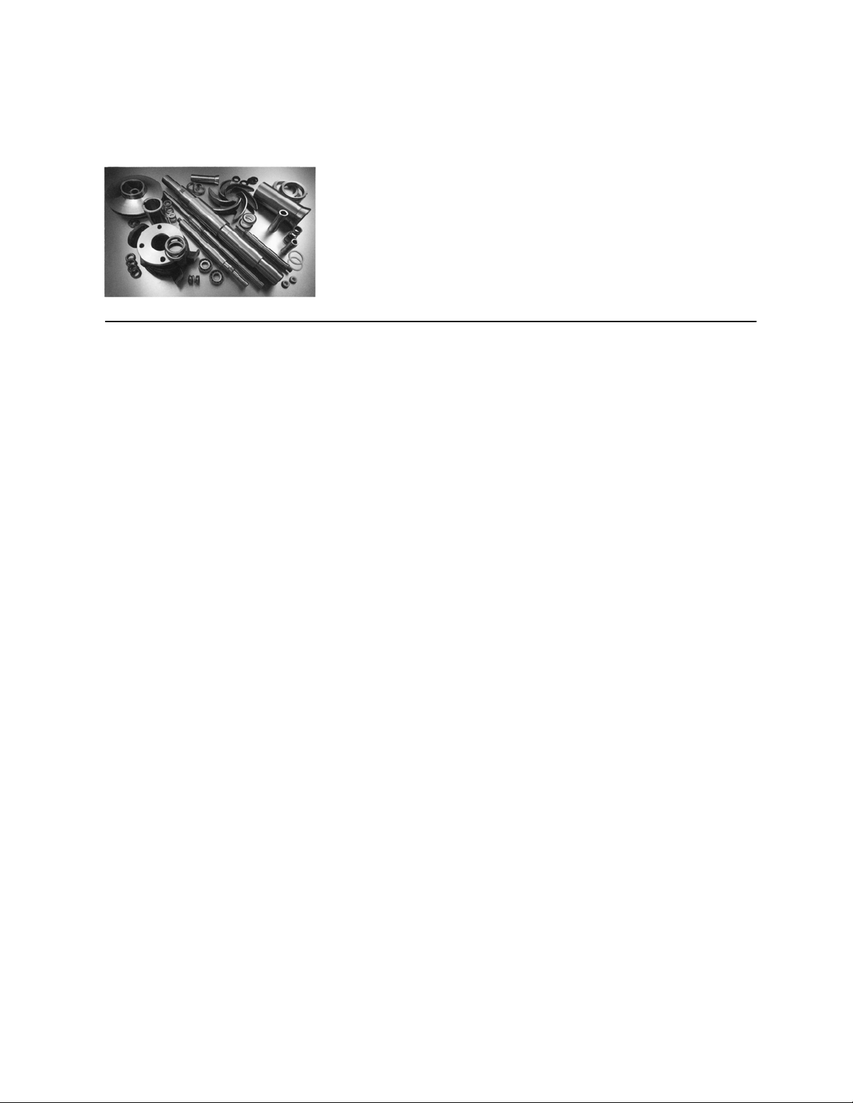
PARTS
The use of genuine Goulds parts will provide the safest and
most reliable operation of your pump. ITT Goulds Pumps ISO
certification and quality control procedures ensure the parts are
manufactured to the highest quality and safety levels.
Please contact your local Goulds representative for details on
genuine Goulds parts.
S-8
Page 12

8 3996 IOM 9/2010
Page 13

SAFETY
DEFINITIONS......................................9
GENERAL PRECAUTIONS .............................10
EXPLOSION PREVENTION .............................10
SPECIAL ATEX CONSIDERATIONS........................10
ATEX IDENTIFICATION ..............................11
INTENDED USE ....................................11
CONDITION MONITORING ............................11
DEFINITIONS
1
These pumps have been designed for safe and reliable
operation when properly used and maintained in
accordance with instructions contained in this manual. A
pump is a pressure containing device with rotating parts
that can be hazardous. Operators and maintenance
personnel must realize this and follow safety measures.
ITT Industries Goulds Pumps shall not be liable for
physical injury, damage or delays caused by a failure to
observe the instructions in this manual.
Throughout this manual the words WARNING,
CAUTION, ELECTRICAL, ATEX, and NOTE are
used to indicate procedures or situations which require
special operator attention:
! WARNING
s
Operating procedure, practice, etc. which, if not
correctly followed, could result in personal injury or
loss of life.
$
Operating procedure, practice, etc. which, if not
followed, could result in damage or destruction of
equipment.
CAUTION
EXAMPLES
! WARNING
s
Pump shall never be operated without coupling guard
installed correctly.
! CAUTION
$
Throttling flow from the suction side may cause
cavitation and pump damage.
Improper impeller adjustment could cause contact
!
between the rotating and stationary parts, resulting
in a spark and heat generation.
! WARNING
s
Lock out driver power to prevent electric shock,
accidental start-up and physical injury.
NOTE: Proper alignment is essential for long pump
life.
If equipment is to be installed in a potentially
!
explosive atmosphere and these procedures are not
followed, personal injury or equipment damage
from an explosion may result.
Particular care must be taken when the electrical
"
power source to the equipment is energized.
NOTE: Operating procedure, condition, etc. which is
essential to observe.
! WARNING
s
Particular care must be taken when the electrical
power source to the equipment is energized.
3996 IOM 9/2010 9
Page 14
GENERAL PRECAUTIONS
! WARNING
s
Personal injuries will result if procedures outlined in
this manual are not followed.
NEVER apply heat to remove impeller, It
may explode to due trapped liquid.
C
NEVER use heat to disassemble pump due to
risk of explosion from trapped liquid.
C
NEVER operate pump without coupling
AC
AD
guard correctly installed.
NEVER operate pump beyond the rated
conditions to which the pump was sold.
NEVER start pump without proper prime.
AD
EXPLOSION PREVENTION
AC
B
C
C
AC
AD
AC
NEVER run pump below recommended
minimum flow or when dry.
ALWAYS lock out power to the driver before
performing pump maintenance.
NEVER operate pump without safety devices
installed.
NEVER operate pump with discharge valve
closed.
NEVER operate pump with suction valve
closed.
DO NOT change conditions of service
without approval of an authorized Goulds
representative.
In order to reduce the possibility of accidental explosions in atmospheres containing explosive gasses and/or dust,
!
the instructions under the ATEX symbol must be closely followed. ATEX certification is a directive enforced in
Europe for non-electrical and electrical equipment installed in Europe. ATEX requirements are not restricted to
Europe. They are useful guidelines for equipment installed in any potentially explosive environment.
When pumping unit is installed in a potentially explosive atmosphere, the instructions after the Ex symbol must be
!
followed. Personal injury and/or equipment damage may occur if these instructions are not followed. If there is any
question regarding these requirements or if the equipment is to be modified, please contact a Goulds representative
before proceeding.
SPECIAL ATEX CONSIDERATIONS
All installation and operation instructions in this manual
must be strictly adhered to. In addition, care must be
taken to ensure that the equipment is properly maintained.
This includes but is not limited to:
1. Monitoring the pump frame and liquid end
temperature.
2. Maintaining proper bearing lubrication.
3. Ensuring that the pump is operated in the intended
hydraulic range.
10 3996 IOM 9/2010
Page 15
ATEX IDENTIFICATION
For a pumping unit (pump, seal, coupling, motor and
pump accessories) to be certified for use in an ATEX
classified environment, the proper ATEX identification
must be present.
The ATEX tag will be secured to the pump or the
baseplate on which it is mounted. A typical tag will look
like this:
The CE and the EX designate the ATEX compliance.
The code directly below these symbols reads as follows:
II = Group 2
2 = Category 2
G/D = Gas and Dust present
T"x" =
Temperature class, can be T1 to T6
(see Table 1)
Table 1
Code Max permissible
surface temperature
o
F(oC)
T1 842 (450) 700 (372)
T2 572 (300) 530 (277)
T3 392 (200) 350 (177)
T4 275 (135) 235 (113)
T5 212 (100) Option not available
T6 185 (85) Option not available
The code classification marked on the equipment should
be in accordance with the specified area where the
equipment will be installed. If it is not, please contact
your ITT/Goulds representative before proceeding.
Max permissible
liquid temperature
oF(o
C)
1
INTENDED USEE
The ATEX conformance is only applicable when the
pump unit is operated within its intended use. All
instructions within this manual must be followed at all
times. Operating, installing or maintaining the pump unit
in any way that is not covered in this manual can cause
serious personal injury or damage to the equipment.
CONDITION MONITORINGG
For assistance in selecting the proper instrumentation and
its use, please contact your ITT/Goulds representative.
When installing in a potentially explosive
!
environment, ensure that the motor is properly
certified.
This includes any modification to the equipment or use of
parts not provided by ITT/Goulds. If there is any
question regarding the intended use of the equipment
please contact an ITT/Goulds representative before
proceeding.
For additional safety precautions, and where noted
!
in this manual, condition monitoring devices
should be used. This includes, but is not limited
to:
·
Pressure gauges
·
Flow meters
·
Level indicators
·
Motor load readings
·
Temperature detectors
·
Bearing monitors
·
Leak detectors
·
PumpSmart control system
3996 IOM 9/2010 11
Page 16

12 3996 IOM 9/2010
Page 17

GENERAL INFORMATION
INTRODUCTION ...................................13
Importance of Instructions ..............................13
Receiving Inspection.................................13
Preservation and Storage ..............................13
Handling Techniques ................................13
RECEIVING THE PUMP ...............................14
NAMEPLATE INFORMATION ...........................15
INTRODUCTION
2
This instruction manual is intended to assist those
involved with the installation, operation, and maintenance
of Goulds Model 3996 pumps. It is recommended that
this manual be thoroughly reviewed prior to installing or
performing any work on the pump or motor.
IMPORTANCE OF INSTRUCTIONS
The design, material and workmanship incorporated in
the construction of Goulds pumps makes them capable of
giving long, trouble-free service. The life and satisfactory
service of any mechanical unit, however, is enhanced and
extended by correct application, proper installation,
periodic inspection and careful maintenance. This
instruction manual was prepared to assist operators in
understanding the construction and correct methods of
installing, operating and maintaining these pumps.
Study thoroughly the following sections and carefully
follow the instructions for installation and operation.
Keep this instruction manual handy for reference. Further
information can be obtained by contacting the
Engineering Application Division, Goulds Pumps, Inc.,
Seneca Falls, New York 13148, or your local branch
office.
! WARNING
s
Goulds Pumps will not be liable for any damages or
delay caused by failure to comply with the provisions
of this instruction manual. This pump is not to be
operated at speeds, working pressures, discharge
pressures or temperatures higher than, nor used with
liquids other than stated in the original order
acknowledgement without written permission of
Goulds Pumps.
RECEIVING INSPECTION
Care should be taken when unloading pumps. If shipment
is not delivered in good order and in accordance with the
Bill-of-Lading, note the damage or shortage on both
receipt and freight bill. MAKE ANY CLAIMS TO THE
TRANSPORTATION COMPANY PROMPTLY.
Instruction sheets on various components as well as the
Installation, Operation and Maintenance (IOM) Manual
for the pump are included in the shipment. DO NOT
DISCARD!
PRESERVATION AND STORAGE
Goulds' normal domestic storage preparation is suitable
for protecting the pump during shipment in covered
trucks. It also provides protection during covered storage
at the jobsite, and for a short period between installation
and start-up.
If the pump is to be idle and exposed to the elements for
an extended period, either before or after installation,
special precautions are required. One approach is to
provide special preservatives and wrapping before
shipment. However, after installation, the protective
wrappings will have been removed. Therefore,
application of preservatives after installation is considered
a good practice. Information about various long-term
preservation and storage options available can be obtained
from your local Goulds representative.
The driver, coupling, and mechanical seal manufacturers
should be contacted for their recommendations on
preservations and protection procedures.
HANDLING TECHNIQUES
Care should be used in moving pumps. Where required
by size of units, slings should be put under both pump and
motor, as shown in Figures 1, 2, and 3 on the next page.
3996 IOM 9/2010 13
Page 18

RECEIVING THE PUMP
Inspect the pump as soon as it is received. Carefully
check that everything is in good order. Make notes of
damaged or missing items on the receipt and freight bill.
File any claims with the transportation company as soon
as possible.
STORAGE REQUIREMENTS
Short Term (Less than 6 months)
Goulds normal packaging procedure is designed to
protect pump during shipping. Upon receipt, store in a
covered and dry location.
Long Term (More than 6 months)
Preservative treatment of bearings and machined surfaces
will be required. Rotate shaft several times every 3
months. Refer to driver and coupling manufacturers for
their long term storage procedures. Store in a covered
and dry location.
NOTE: Long term storage treatment may be
purchased with initial pump order.
HANDLING
! WARNING
s
Pump and components are heavy. Failure to properly
lift and support equipment could result in serious
physical injury, or damage to pumps.
Units with drivers mounted are moved with slings under
the pump casing and driver (Figs. 2 and 3).
Fig. 2
Or with hooks through the holes in the frame mounted
support or with slings through the large openings in the
casing mounted support.
Use care when moving pumps. Lifting equipment must be
able to adequately support the entire assembly. Hoist bare
pump using suitable hooks through the holes in the frame
mounted support or suitable slings through the large
openings in the casing mounted support (Fig. 1).
Fig. 1
Fig. 3
! WARNING
s
Units with drivers mounted can be top heavy. Driver
weight could cause the assembled unit to overturn
and could result in serious physical injury, or damage
to pumps.
14 3996 IOM 9/2010
Page 19

NAMEPLATE INFORMATION
Every pump has two Goulds nameplates that provide
information about the pump. The tags are located on the
casing and bearing frame.
Description Fig. No. Example
Pump Casing Tag - provides information
about the pump’s hydraulic
characteristics. Note the format of the
pump size: Discharge x Suction - Nominal
maximum Impeller Diameter in inches.
(Example: 2x3-8)
(Figs.4&5).
Fig. 4
English
Fig. 5
Metric
When ordering spare parts, you will need to identify
pump model, size, serial number, and the item number of
required parts. Information can be taken from the pump
casing tag. Item numbers can be found in this manual.
2
Bearing Frame Tag - provides
information on the lubrication system used
(Fig. 6).
ATEX Tag - If applicable, your pump
unit may have the following ATEX tag
affixed to the pump and/or baseplate. See
the Safety section for a description of the
symbols and codes
(Fig. 7).
3996 IOM 9/2010 15
Fig. 6
Fig. 7
Page 20

16 3996 IOM 9/2010
Page 21

INSTALLATION
SITE/FOUNDATION .................................17
Location .......................................17
Foundation and Baseplate ..............................17
PIPING .........................................17
ALIGNMENT .....................................19
When pumping unit is installed in a potentially explosive atmosphere, the instructions after the Ex symbol must be
!
followed. Personal injury and/or equipment damage may occur if these instructions are not followed. If there is any
question regarding these requirements or if the equipment is to be modified, please contact a Goulds representative
before proceeding.
SITE/FOUNDATION
LOCATION
Pumping unit should be placed as close as practical to the
source of supply. Floor space and head room allotted to
the unit must be sufficient for inspection and
maintenance. Be sure to allow for crane or hoist service.
All equipment being installed must be properly
!
grounded to prevent unexpected static electric
discharge.
PIPING
Guidelines for piping are given in the “Hydraulic Institute
Standards,” available from:
Hydraulic Institute
30200 Detroit Road
Cleveland, OH 44145-1967
and must be reviewed prior to pump installation.
! WARNING
A
s
Never draw piping into place by forcing at the
flanged connections of the pump. This may impose
dangerous strains on the unit and cause misalignment between pump and driver. Pipe strain will
adversely affect the operation of the pump resulting
in physical injury and damage to the equipment.
1. Piping runs should be as short as possible to
minimize friction losses.
2. It is suggested that expansion loops be properly
designed and installed in suction and/or discharge
lines when handling liquids at elevated temperatures,
so thermal expansion of piping will not draw pump
out of alignment.
FOUNDATION AND BASEPLATE
Model 3996 In-Line pumps are designed to be mounted
directly in, and supported by the piping. No supports
under the pump are required. Pipe supports should be
located close to the pump and be designed to support the
weight of the complete unit (pump and motor).
3. The piping should be arranged to allow pump
flushing prior to removal of the unit on services
handling hazardous liquids.
4. Carefully clean all pipe parts, valves and fittings, and
pump branches prior to assembly.
5. All piping must be supported independently of, and
line up naturally with, the pump flanges. Table 2
shows piping flange alignment criteria.
Table 2
Piping Flange Alignment
Type Criteria
Axial
Parallel
Concentric
6. Bottom of casing should be supported by a solid
foundation or casing feet should be used.
Flange gasket thickness ± 0.8 mm (.03 in.).
0.001 mm/mm (.001 in./in.) of flange
diameter to a maximum of 0.8 mm (.03 in.).
Flange bolts should easily install by hand.
3
3996 IOM 9/2010 17
Page 22

SUCTION PIPING
!
s
A
NPSHAmust always exceed NPSHRas shown on
Goulds performance curves received with order.
(Reference Hydraulic Institute for NPSH and pipe
friction values needed to evaluate suction piping).
CAUTION
Suction Head/Flooded Suction Conditions
1. An isolation valve should be installed in the suction
line at least two (2) pipe diameters from the pump
suction to permit closing of the line for pump
inspection and maintenance.
2. Keep suction pipe free from air pockets.
$
A
Pump must never be throttled from suction side.
Properly designed and installed suction piping is a
necessity for trouble-free pump operation. Suction piping
should be flushed BEFORE connection to the pump.
1. Use of elbows close to the pump suction flange
should be avoided. There should be a minimum of
two (2) pipe diameters of straight pipe [five (5) pipe
diameters is preferred] between the elbow and
suction inlet. Where used, elbows should be long
radius.
2. Use suction pipe one (1) or two (2) sizes larger than
the pump suction, with a reducer at the suction
flange. Suction piping should never be of smaller
diameter than the pump suction.
3. Reducers, if used, should be eccentric and located at
the pump suction flange with sloping side down.
4. A suction screen should be installed prior to initial
start-up and when suction system has been opened
for work. The screen should be of the cone type with
a net area equal to at least three (3) times the cross
sectional area of the suction pipe. The mesh of the
screen should be sized to prevent particles larger than
1.6 mm (1/16 in.) from entering the pump and should
be installed in a spool piece to allow removal for
cleaning. The screen should remain in the system
until periodic inspection shows system is clean.
5. Separate suction lines are recommended when more
than one pump is operating from the same source of
supply.
Suction Lift Conditions
1. Suction pipe must be free from air pockets.
2. Suction piping must slope upwards to pump.
CAUTION
3. Piping should be level or slope gradually downward
from the source of supply.
4. No portion of the piping should extend below pump
suction flange.
5. The size of entrance from supply should be one (1) or
two (2) sizes larger than the suction pipe.
6. The suction pipe must be adequately submerged
below the liquid surface to prevent vortices and air
entrainment at the supply.
DISCHARGE PIPING
Properly designed and installed discharge piping is a
necessity for trouble-free pump operation. Discharge
piping should be flushed BEFORE connection to
the pump.
1. Isolation and check valves should be installed in
discharge line. Locate the check valve between
isolation valve and pump; this will permit inspection
of the check valve. The isolation valve is required
for priming, regulation of flow, and for inspection
and maintenance of pump. The check valve prevents
pump or seal damage due to reverse flow through the
pump when the driver is turned off.
2. Increasers, if used, should be placed between pump
and check valves.
3. Cushioning devices should be used to protect the
pump from surges and water hammer if quick-closing
valves are installed in system.
BYPASS PIPING
Systems that require operation at reduced flows for
prolonged periods should be provided with a bypass line
connected from the discharge side (before any valves) to
the source of suction.
3. All joints must be air tight.
4. A means of priming the pump must be provided.
A minimum flow orifice can be sized and installed in
bypass line to preclude bypassing excessive flows.
Consult nearest sales office or factory for assistance in
sizing orifice.
An automatic recirculation control valve and/or solenoid
operated valve should be considered if a constant bypass
(i.e. orifice) is not possible.
18 3996 IOM 9/2010
Page 23

AUXILIARY PIPING
Auxiliary piping may be required for seal chamber cover
cooling, mechanical seal flush or other special features
supplied with the pump. Consult pump data sheet for
specific auxiliary piping recommendations.
If seal chamber cover cooling is required, follow guidelines
listed below.
1. Flows of 4 l/min. (1 GPM) will generally satisfy
cooling requirements.
2. Cooling water pressure should not exceed
2
7.0 kg/cm
(100 psig).
ALIGNMENT
FINAL PIPING CHECK
After connecting the piping to pump:
1. Rotate shaft several times by hand to be sure that
there is no binding and all parts are free.
2. Check alignment, per alignment criteria outlined
previously, to determine if pipe strain has affected
alignment. If pipe strain exists, correct piping.
Alignment between pump and motor is built in by use of
machined lock fit between the C-face motor and motor
support. No further alignment is normally required.
There is one exception to this. The Model 3196
horizontal ANSI pump bearing frame can be used in the
Model 3996. This frame may be used in emergencies or
when it is desired to minimize inventory. The Model
3196 frame will not give built-in alignment, and normal
alignment procedures must be performed. The Model
3196 frame can be identified by the foot and cooling
jacket on the side.
SHAFT ALIGNMENT
Many users now require a 0.002" T.I.R. alignment to gain
a greater mean time between failure (MTBF). All 3996’s
that have been shipped after 1/9/90 have been aligned at
the factory to .002" T.I.R.
Assembly procedures have been developed to align the
pump shaft and the driver shaft to .002" T.I.R. Each
pump is assembled using a torque range of +
recommended torque value of the bolts. If .002" T.I.R.
alignment is required by the customer, a final alignment
must be done in the field.
10% of the
3. Move shaft assembly (shaft, housing, and impeller)
away from casing angle face, by adjusting the
bearing housing. A 1/4 turn of bearing housing jack
bolts is sufficient to ensure the impeller does not ride
on the casing angle face. Proper indication cannot be
done with the impeller touching the angle face.
4. Tighten motor hold down bolts in a criss cross
pattern to the recommended torque.
(Refer to the torque values listed in Table 3.)
5. Tighten the motor support bolts in a criss cross
pattern to 90% of the recommended torque value of
the bolts. For example, if the recommended torque
value for the bolts is 60 ft.-lbs., tighten bolts to 54
ft.-lbs.
6. Tighten casing bolts in a criss cross pattern to 90% of
the recommended torque value.
7. Attach a dial indicator to the driver shaft and mark
the pump shaft so the indicator always contacts the
same location on the pump shaft.
8. Rotate both shafts in the same direction and record
the indicator readings every 90° degrees (4 places).
3
The following is the procedure that has been developed
for the use in the field and on our assembly floor to obtain
0.002" shaft to shaft alignment.
3996 Shaft Alignment Procedure
1. Inspect all machined fits for signs of contamination
or damage. All fits must be clean. If the pump is
new this step is not necessary.
2. Loosen all motor, motorsupport, and casing bolts, but
do not remove.
NOTE: Make sure jack bolts on the casing are
backed off.
3996 IOM 9/2010 19
9. Incrementally increase the torque value and begin to
tighten the necessary bolts to bring the shafts into
alignment. Do no exceed 110% of the recommended
torque values. After each series of tightening, repeat
Step #5 until the desired alignment is achieved.
NOTE: Indicate off the hub to the motor lock I.D., in
the motor support, when supplying the pump less
motor.
10. Reset the clearance between the impeller and casing
angle face to .008 (.015 if using the high temperature
option). Ensure the bearing housing jack bolts are
secured.
Page 24

NOTE: Tighten coupling bolts and hub set screw
onto shaft. Torquing of these components is not done
at the factory, yet is required at the site. Please
reference the coupling manufacturers instructions for
correct torque levels.
Table 3
Fastener Size and Recommended
Torque Values
Fastener
Standard
SAE
1
Torque values shown for SAE fasteners are based on
dry threads at 75% of proof load for ASTM307
Grades A and B (SAE Grade 1) fasteners.
For lubricated, plated, or PFTE-coated threads, use
75% of torque values shown.
Fastner
Nominal Size
5
16
3
8
7
16
1
2
5
8
3
4
7
8
1 228
Recommended
Torque
6
10
18
27
53
94
152
1
lb.-ft.
20 3996 IOM 9/2010
Page 25

OPERATION
PREPERATION FOR STARTUP ..........................21
Checklist .......................................21
STARTING PUMP...................................25
OPERATION ......................................25
SHUTDOWN ......................................26
FINAL ALIGNMENT .................................26
PREPARATION FOR STARTUP
CHECKLIST
When installing in a potentially explosive
!
environment, ensure that the motor is properly
certified.
1. Checking Rotation
$
Serious damage may result if pump is run in the
wrong rotation.
a. Lock out power to driver.
! WARNING
s
Lock out driver power to prevent accidental start-up
and physical injury.
b. Make sure coupling hubs are securely fastened to
the shafts and the coupling spacer has been
removed.
NOTE: Pump is shipped with coupling spacer
removed.
c. Unlock driver power.
d. Make sure everyone is clear. Jog driver just long
enough to determine the direction of rotation.
Rotation must correspond to arrow on bearing
housing.
CAUTION
See Preventive Maintenance section for lubrication
recommendations.
Pure Oil Mist Lubrication
Pure oil mist is an optional feature for the Model 3996.
Follow oil mist generator manufacturer’s instructions.
The inlet and outlet connections are located on the side of
the bearing frame.
See Preventive Maintenance section for lubrication
recommendations and connection locations.
! WARNING
s
Operation of the unit without proper lubrication will
cause bearing failure and pump seizure.
3. Alignment - As described in the Alignment section,
alignment is normally built-in and need not be
rechecked.
4. Stuffing Box - Pumps are shipped without packing,
lantern ring or split gland installed. These are
included with the box of fittings shipped with the
pump and must be installed before start-up.
Packed stuffing boxes are not allowed in an ATEX
!
classified environment.
4
e. Lock out power to driver.
2. Lubrication
Bearings must be lubricated properly in order to
!
prevent excess heat generation, sparks and
premature failure.
Grease Lubrication
Greased lubricated ball bearings are standard on the
Model 3996 units.
The bearings are greased at the factory.
3996 IOM 9/2010 21
The mechanical seal used in an ATEX classified
!
environment must be properly certified.
a. Packing - Stuffing box packing, lantern ring and
gland are in the box of fittings supplied with the
pump. Install 3 rings of packing, the two piece
lantern ring (notched sides facing), 2 more rings
of packing and the gland. Twist rings sideways
instead of straight out when putting them on the
shaft to avoid damaging them. Seat each ring
firmly as it is installed, and stagger the joints
90°. Gland should be drawn up only finger tight.
Page 26

Packing must not run dry. If the pumped liquid
is clean, gland leakage of 40-60 drops per minute
is satisfactory. If the liquid is dirty, connect a
clean liquid flush to the lantern ring connection
to keep solids out of the packing.
Occasionally, the stuffing box is below
atmospheric pressure (suction under vacuum,
etc.). Under these conditions, supply sealing
liquid through a line from the discharge of the
pump to the lantern ring connection. Leakage
from the box can be piped away through the ½
inch drain connection in the casing.
b. Mechanical Seals - When mechanical seals are
supplied, they are installed in the pump.
Mechanical seals must not run dry, or in
abrasives. Connect recirculation, flush and/or
cooling flows as required, following instructions
on the seal print supplied for the order.
5. Stuffing Box Lubrication/Cooling - Check to be
sure that any required auxiliary piping is installed and
functioning. If cooling and/or flushing from an
outside source is being used, establish these flows.
6. Check Impeller Clearance -
Table 4
Impeller Clearances
Cold Temperature Clearances for Various
Service Temperatures
3996
Service
Temperature
From -20 to
150°F (-29 to
66°C)
Up to 175°F
(79°C)
Up to 200°F
(93°C)
Up to 250°F
(121°C)
Up to 300°F
(149°C)
Up to 350°F
(177°C)
ST MT
inches mm inches mm
0.005 0.13 0.008 0.20
0.005 0.13 0.008 0.20
0.005 0.13 0.008 0.20
0.006 0.16 0.009 0.23
0.007 0.19 0.010 0.26
0.009 0.22 0.012 0.29
The impeller clearance setting procedure must be
!
followed. Improperly setting the clearance or not
following any of the proper procedures can result
in sparks, unexpected heat generation and
equipment damage.
Prior to starting the pump, the impeller clearance
must be checked. The pump efficiency is maintained
when the proper impeller clearance is set. The
optimum hydraulic performance is attained by setting
the impeller front clearance at the factory to
predetermined limits which are consistent with
service conditions.
The maximum impeller setting should not be set
more than .005 inch (0.13) above values in Table 4 or
significant performance degredation will result.
Service temperature in an ATEX classified
!
environment is limited to the area classification
specified on the ATEX tag affixed to the pump
(reference Table 1 in the Safety section for ATEX
classifications).
Also, for pumpage temperatures above 200° F (93°
C) the cold (ambient) setting must be increased per
Table 4. This is necessary to prevent the impeller
from contacting the casing due to differential
expansion from the higher operating temperatures.
Up to 400°F
(204°C)
Up to 450°F
(232°C)
Up to 500°F
(260°C)
7. Couple Pump and Driver
! WARNING
s
Lock out driver power to prevent accidental rotation
and physical injury.
0.01 0.25 0.013 0.32
0.011 0.28 0.014 0.35
0.012 0.30 0.015 0.38
Fig. 8
22 3996 IOM 9/2010
Page 27

The coupling used in an ATEX classified
!
environment must be properly certified.
a. Install and lubricate coupling per manufacturer’s
instructions.
Fig. 9
! WARNING
s
Never operate a pump without coupling guard
properly installed. Refer to Appendix II for coupling
guard installation instructions. Personal injury will
occur if pump is run without coupling guard.
8. Priming - Never start the pump until it has been
properly primed. Several different methods of priming
can be used, depending upon type of installation and
service involved.
Pumps must be fully primed at all times during
!
operation.
Suction Supply Above Pump
1. Slowly open the suction valve (Fig. 8).
2. Open air vents on the suction and discharge piping,
casing, seal chamber, and seal piping, if provided, until all
air is vented and only liquid flows out.
3. Close the vents.
Suction Supply Below Pump
A foot valve and outside source of liquid may be used to
prime the pump. Outside source of liquid can come from
a priming pump, pressurized discharge line, or other
supply (Fig. 9 and 10).
Fig. 10
b. Install coupling guard. Refer to Coupling Guard
Installation and Disassembly Section Appendix
II.
1. Close discharge valve and open air vents in suction
and discharge piping, casing, seal chamber and seal
piping, if provided.
2. Open valve in outside supply line until all air is
vented and only liquid flows out.
! WARNING
s
When handling hazardous and/or toxic fluids, proper
personal protective equipment is required. If pump is
being drained, precautions must be taken to prevent
physical injury. Pumpage must be handled and
disposed of in conformance with applicable
regulations.
3. Close the vents and then the outside supply line.
Other Methods of Priming Pump
Priming by ejector.
·
Priming by automatic priming pump.
·
4
The coupling guard used in an ATEX classified
!
environment must be constructed from a
non-sparking material.
3996 IOM 9/2010 23
Page 28

START-UP PRECAUTIONS
1. All equipment and personal safety related devices and
controls must be installed and operating properly.
2. To prevent premature pump failure at initial start-up
due to dirt or debris in the pipe system, ensure the
pump can be run continuously at full speed and flow
for 2 to 3 hours.
3. Variable speed drivers should be brought to rated
speed as quickly as possible.
4. Variable speed drivers should not be adjusted or
checked for speed governor or overspeed trip settings
while coupled to the pump at initial start-up. If
settings have not been verified, uncouple the unit and
refer to driver manufacturer’s instructions for
assistance.
5. Pumpage temperatures in excess of 93° C (200° F) will
require warm-up of pump prior to operation. Circulate a
small amount of pumpage through the pump until the
casing temperature is within 38° C (100° F) of the
pumpage temperature and evenly heated.
NOTE: Warm-up rate should not exceed 1.4° C
(2.5° F) per minute.
24 3996 IOM 9/2010
Page 29

STARTING PUMP
1. Make sure suction valve and any recirculation or
cooling lines are open.
2. Fully close or partially open discharge valve as
dictated by system conditions.
3. Start Driver.
!
$
A
Immediately observe pressure gauges. If discharge
pressure is not quickly attained - stop driver, reprime
and attempt to restart.
CAUTION
OPERATION
GENERAL CONSIDERATIONS
! CAUTION
$
A
Always vary capacity with regulating valve in the
discharge line. NEVER throttle flow from the suction
side.
! CAUTION
$
A
Driver may overload if the pumpage specific gravity
(density) is greater than originally assumed, or the
rated flow rate is exceeded.
4. Slowly open discharge valve until the desired flow
is obtained.
!
$
A
Observe pump for vibration levels, bearing
temperature and excessive noise. If normal levels are
exceeded, shut down and resolve.
CAUTION
OPERATING AT REDUCED
CAPACITY
! WARNING
s
DO NOT operate pump below minimum rated flows
or with suction and/or discharge valve closed. These
conditions may create an explosive hazard due to
vaporization of pumpage and can quickly lead to
pump failure and physical injury.
! CAUTION
$
A
Damage occurs from:
4
! CAUTION
$
A
Always operate the pump at or near the rated
conditions to prevent damage resulting from
cavitation or recirculation.
1. Increased vibration levels - Affects bearings,
stuffing box or seal chamber, and mechanical seal.
2. Increased radial loads - Stresses on shaft and
bearings.
3. Heat build up - Vaporization causing rotating parts to
score or seize.
4. Cavitation - Damage to internal surfaces of pump.
OPERATING UNDER FREEZING
CONDITIONS
Exposure to freezing conditions, while pump is idle,
could cause liquid to freeze and damage the pump.
Liquid inside pump should be drained. Liquid inside
cooling coils, if supplied, should also be drained.
3996 IOM 9/2010 25
Page 30

SHUTDOWN
1. Slowly close discharge valve.
2. Shut down and lock driver to prevent accidental
rotation.
FINAL ALIGNMENT
Alignment procedures must be followed to prevent
!
unintended contact of rotating parts. Follow
coupling manufacturer's coupling installation and
operation procedures.
1. Run the unit under actual operating conditions for a
sufficient length of time to bring the pump and driver
and associated system up to operating temperature.
! WARNING
s
When handling hazardous and/or toxic fluids, proper
personal protective equipment should be worn. If
pump is being drained, precautions must be taken to
prevent physical injury. Pumpage must be handled
and disposed of in conformance with applicable
environmental regulations.
2. Remove coupling guard. Refer to coupling guard
installation and disassembly instructions in Appendix
II.
3. Check alignment while unit is still hot per alignment
procedure in the Installation Section.
4. Reinstall coupling guard.
26 3996 IOM 9/2010
Page 31

PREVENTIVE MAINTENANCE
GENERAL COMMENTS ...............................27
MAINTENANCE SCHEDULE ............................27
LUBRICATION ....................................28
MAINTENANCE OF BEARINGS ..........................28
IMPELLER CLEARANCE SETTING........................31
VIBRATION ......................................32
GENERAL COMMENTS
A routine maintenance program can extend the life of your pump. Well maintained equipment
will last longer and require fewer repairs. You should keep maintenance records, this will help
pinpoint potential causes of problems.
The preventive maintenance section must be adhered to in order to keep the applicable ATEX classification of the
!
equipment. Failure to follow these procedures will void the ATEX classification for the equipment.
MAINTENANCE SCHEDULE
ROUTINE MAINTENANCE
Bearing lubrication
·
Seal monitoring
·
Vibration analysis
·
Discharge pressure
·
Temperature monitoring
·
ROUTINE INSPECTIONS
Check level and condition of oil through sight glass
·
on bearing frame.
Check for unusual noise, vibration and bearing
·
temperatures.
Inspect pump and piping for leaks.
·
Check seal chamber/stuffing box leakage.
·
Mechanical Seal: Should be no leakage.
Packing: Excessive leakage requires adjust
ment or possible packing replacement. Re
fer to Section 4 - Operation for packing
gland adjustment.
3 MONTH INSPECTIONS
Check the foundation and the hold-down bolts for
·
tightness.
5
If the pump has been left idle, check the packing.
·
Replace if required.
Oil should be changed at least every 3 months (2000
·
hours) or more often if there are any adverse
atmospheric conditions or other conditions which
might contaminate or break down the oil. If it is
cloudy or contaminated as seen by inspection
through the sight glass, it should be changed
immediately.
Check the shaft alignment. Realign if required.
·
ANNUAL INSPECTIONS
Check the pump capacity, pressure and power. If
·
pump performance does not satisfy your process
requirements, and the process requirements have not
changed, the pump should be disassembled,
-
-
inspected, and worn parts should be replaced.
Otherwise, a system inspection should be done.
INSPECTION INTERVALS
Inspection intervals should be shortened appropriately if
the pumpage is abrasive and/or corrosive,
or if the environment is classified as potentially
!
explosive.
3996 IOM 9/2010 27
Page 32

LUBRICATION
Pump bearings are normally grease lubricated and are
lubricated at the factory. Regrease at approximately 3-6
month intervals, until grease comes out the oil caps which
MAINTENANCE OF BEARINGS
Do not insulate bearing housings as this can result
!
in excess heat generation, sparks, and premature
failure.
Service temperature in an ATEX classified environ-
!
ment is limited to the area classification specified on
the ATEX tag affixed to the pump (reference Table 1
in the Safety section for ATEX classifications).
GREASE LUBRICATED BEARINGS
Grease lubricated bearings are pre-lubricated at the
factory. Regrease bearings every 2000 operating hours
or 3 months, whichever occurs first.
Regrease Procedure
NOTE: When regreasing there is danger of
impurities entering the bearing housing. The grease
container, the greasing device, and fittings must be
clean.
1. Wipe dirt from both grease fittings (Fig. 11).
2. Remove two grease relief plugs from side of frame
opposite grease fittings.
3. Fill both grease cavities through grease fittings with
recommended grease until fresh grease comes out of
the relief holes. Reinstall grease relief plugs until
immediately prior to starting pump.
serve as grease relief fittings. Use a sodium or lithium
base grease, NLGI #2 consistency. Follow motor and
coupling manufacturer's lubrication instructions.
NOTE: The bearing temperature usually rises after
regreasing due to an excess supply of grease. Temperatures will return to normal after pump has run and
purged the excess from the bearings, usually two to
four hours. Grease relief plugs should be removed
during this period, and replaced when temperature
has stabilized.
For most operating conditions a lithium based mineral oil
grease of NLGI consistency number 2 is recommended.
This grease is acceptable for bearing temperatures of
-15°C to 110°C (5°F ro 230°F).
Bearing temperatures are generally about 20°F (18°C)
higher than bearing housing outer surface temperature.
Some acceptable greases are:
NLGI Consistency 2
Exxon Unirex N2
Mobil Mobilux EP2
Sunoco Multipurpose EP
SKF LGMT 2
! CAUTION
$
Never mix greases of different consistency (NLGI 1
or 3 with NLGI 2) or different thickener. For
example, never mix a lithium base grease with a
polyurea base grease.
NOTE: If it is necessary to change grease type or
consistency, the pump must be disassembled and the
old grease removed from the bearings.
Fig. 11
28 3996 IOM 9/2010
Page 33

PURE OIL MIST LUBRICATED
BEARINGS (OPTIONAL)
! WARNING
s
Pumps are shipped without oil. Oil mist lubricated
bearings must be lubricated at the job site.
Some acceptable oils are:
Exxon Teresstic EP68
Mobil
Mobil DTE 26 300 SSU
@ 40°C (100°F)
1. Follow oil mist system supplier’s instructions.
2. Connect oil mist supply lines to upper and center
tapped connection.
3. Connect drain line to bottom tapped connection
(Fig. 12).
Oil mist lubrication is required above pumpage
temperature of 232°C (450° F), but may be used at lower
temperatures.
A high quality turbine oil with rust and oxidation
inhibitors should be used. For the majority of operational
conditions, bearing temperatures will run between 50°C
(120°F) and 82°C (180°F). In this range, an oil of ISO
viscosity grade 68 at 40°C (100°F) is recommended. If
bearing temperatures exceed 82°C (180°F), use ISO
viscosity grade 100.
Sunoco Sunvis 968
Royal Purpal
SYNFILM ISO VG 68
Synthetic Lube
Fig. 12
5
STUFFING BOX
PACKED STUFFING BOX
Periodically inspect stuffing box to see that there is
sufficient leakage to lubricate the packing and maintain a
cool box. Never draw up packing so that the stuffing box
heats, as this will cause damage to both packing and
sleeve. Draw up gland nuts slowly and evenly and only
when pump is running.
MAINTENANCE OF SHAFT SEALS
The mechanical seal used in an ATEX classified
!
environment must be properly certified.
The mechanical seal must be properly flushed.
!
Failure to do so will result in excess heat
generation and seal failure.
MECHANICAL SEALS
When mechanical seals are furnished, a manufacturer’s
reference drawing is supplied with the data package. This
After pump has been in operation for some time and the
packing has been completely “run-in”, at least 40 to 60
drops per minute of the liquid should be allowed to trickle
from the stuffing box at all times for cooling and
lubricating the packing and shaft sleeve.
drawing should be kept for future use when performing
maintenance and adjusting the seal. The seal drawing will
also specify required flush liquid and attachment points.
The seal and all flush piping must be checked and
installed as needed prior to starting the pump.
The life of a mechanical seal depends on various factors
such as cleanliness of the liquid handled and its
lubricating properties. Due to the diversity of operating
conditions it is, however, not possible to give definite
indications as to its life.
3996 IOM 9/2010 29
Page 34

! WARNING
s
Never operate the pump without liquid supplied to
mechanical seal. Running a mechanical seal dry,
even for a few seconds, can cause seal damage and
must be avoided. Physical injury can occur if
mechanical seal fails.
PACKED STUFFING BOX
Packed stuffing boxes are not allowed in an ATEX
!
classified environment.
Packing operation can be inspected without shutting
down or disassembling the pump. During normal
operation the packing should leak approximately one drop
per minute. If the drip rate is higher or lower than one
drop per minute then an adjustment of the gland may be
required. To slow down the leakage rate, the two gland
bolts should be tightened evenly one-quarter (¼) turn
each until the desired leakage rate is obtained. NEVER
over-tighten packing to the point where less than one drop
per minute is observed. Overtightening can cause
excessive wear and power consumption during operation.
If the packing cannot be tightened to obtain less than two
drops per minute, then the packing may need to be
replaced and the packing installation procedures under
Operation should be followed.
Dynamic Seal with Packing
Fig. 13
Static Seal - A static seal is used to prevent leakage when
the pump is shut down. This is either a lip seal,
elastomeric face seal, or graphite packing. The lip and
elastomeric face seal require no maintenance other than
replacement when leakage becomes excessive. The
packing should be installed as stuffing box packing. It is a
special type designed to run dry, so it does not require an
external flush.
! CAUTION
$
Never attempt to replace packing until the driver is
properly locked out and the coupling spacer is
removed.
DYNAMIC SEAL
Dynamic seals are not allowed in an ATEX
!
classified environment.
Dynamic Seal Components
Repeller - The dynamic repeller effectively prevents
leakage of pumpage through the stuffing box when the
pump is operating under published acceptable conditions.
Dynamic seal parts do not wear substantially to affect
operation unless the service is particularly abrasive or
corrosive. Refer to Disassembly and Reassembly Section
for maintenance, disassembly, and repair.
Dynamic Seal with Chekseal™
Fig. 14
30 3996 IOM 9/2010
Page 35

IMPELLER CLEARANCE SETTING
The impeller clearance setting procedure must be
!
followed. Improperly setting the clearance or not
following any of the proper procedures can result
in sparks, unexpected heat generation and
equipment damage.
! WARNING
s
Lock out driver power to prevent accidental startup
and physical injury.
(about one flat at a time) backing the bearing housing
(134A) away from the bearing frame until the
indicator shows the proper clearance per Table 3.
8. Evenly tighten locking bolts (370C), then jack bolts
(370D) keeping indicator reading at proper setting.
9. Check shaft for free turning.
10. Replace coupling guard.
A change in pump performance may be noted over time
by a drop in head or flow or an increase in power
required. Performance can usually be renewed by
adjusting the impeller clearance. Two techniques are
given to set the impeller clearance, the dial indicator
method and the feeler gauge method.
DIAL INDICATOR METHOD
1. Remove coupling guard.
2. Remove coupling.
3. Set indicator so that button contacts either the shaft
end or against face of coupling (Fig. 38).
4. Loosen jam nuts (423) on jack bolts (370D) and back
bolts out about two turns.
5. Tighten each locking bolt (370C) evenly, drawing the
bearing housing (134A) towards the bearing frame
(228) until impeller contacts the casing. Turn the
shaft to ensure contact is made.
FEELER GAUGE METHOD
1. Remove coupling guard.
2. Loosen jam nuts (423) on jack bolts (370D) and back
bolts out about two turns (Fig. 16).
3. Tighten locking bolts (370C) evenly, drawing
bearing housing (134A) towards frame (228) until
impeller contacts the casing. Turn shaft to ensure
contact is made.
4. Using a feeler gauge, set the gap between the
three locking bolts (370C) and bearing housing
(134A) per impeller clearances in Table 1.
5. Evenly back out bearing housing (134A) using the
three jack bolts (370D) until it contacts the locking
bolts (370C). Evenly tighten jam nuts (423B).
6. Check shaft for free turning.
7. Replace coupling guard.
5
Dial Indicator Method
6. Set indicator to zero and back locking bolt (370C)
out about one turn.
7. Thread jack bolts (370D) in until they evenly contact
the bearing frame. Tighten the jack bolts evenly
3996 IOM 9/2010 31
Fig. 15
Fig. 16
Page 36

VIBRATION
It is good practice to periodically monitor vibration of the
pump. Normally, vibration level will be well below
accepted standards. Of equal
importance is that the vibration level not increase. If a
problem with vibration is encountered, refer to Trouble
Shooting.
32 3996 IOM 9/2010
Page 37

DISASSEMBLY AND REASSEMBLY
REQUIRED TOOLS ..................................33
DISASSEMBLY ....................................33
INSPECTION AND REPLACEMENT........................35
REASSEMBLY.....................................36
ADDITIONAL DETAILS ...............................37
Engineering Data Construction Details .......................38
SECTIONAL VIEWS .................................40
HIGH PRESSURE CAPABILITY ..........................43
REQUIRED TOOLS
·
Wrenches
·
Screwdriver
·
Lifting Sling
·
Rubber Mallet
·
Induction Bearing Heater
·
Bearing Puller
·
Brass Drift Punch
·
Snap-Ring Pliers
·
Torque Wrench with Sockets
·
Allen Wrenches
·
Dial Indicator
·
Micrometer
DISASSEMBLY
The Model 3996 is designed to permit the complete
pullout assembly to be removed without disturbing the
casing or motor. The sectional drawing, parts list and
construction details should be used in conjunction with
the disassembly instructions.
! WARNING
s
Pump components can be heavy. Proper methods of
lifting must be employed to avoid physical injury
and/or equipment damage. Steel toed shoes must be
worn at all times.
·
Cleaning Agents
·
Feeler Gauges
·
Hydraulic Press
·
Leveling Blocks
! WARNING
s
Lock out power supply to driver motor to prevent
accidental startup and physical injury.
2. Shut off all valves controlling flow to and from
pump.
! WARNING
s
Operator must be aware of pumpage and safety
precautions to prevent physical injury.
6
! WARNING
s
The pump may handle hazardous and/or toxic fluids.
Proper personal protective equipment should be
worn. Precautions must be taken to prevent physical
injury. Pumpage must be handled and disposed of in
conformance with applicable environmental
regulations.
NOTE: Before disassembling the pump for overhaul,
ensure all replacement parts are available.
1. Lock out motor
3996 IOM 9/2010 33
3. Drain liquid from piping, flush pump if necessary.
4. Remove auxiliary piping.
5. Unbolt and remove spacer member of coupling.
6. Remove the bolts (370) that hold the frame (228) to
the casing. Jacking bolts (418) are provided to assist
disassembly. Tighten the bolts evenly, a flat at a
time, to jack assembly from casing.
7. Remove casing gasket (351).
Page 38

8. Unscrew impeller (101) from shaft (122). The
threads are right-hand. Prevent the shaft turning by
using a wrench on coupling “flats”. Do not lose or
damage the O-ring (412A) which seals between the
impeller (101) and shaft (122) or shaft sleeve (126).
9. On units with mechanical seal (383).
a. Inside single or double seal – remove gland
stud nuts (355) and carefully slide gland (250)
off studs. Do not damage seal faces.
b. Outside seal – loosen set screws which position
rotary portion of seal and slide seal toward
bearing frame (228). Remove gland stud nuts
(355) and carefully slide gland (250) off studs.
Do not damage seal faces.
10. Remove stud nuts (370H) which hold stuffing box
cover (184) from frame. Do not allow stuffing box to
contact shaft (122), sleeve (126), shaft threads or any
mechanical seal parts. Slide sleeve (126), if any, off
shaft (122).
11. On units with mechanical seal, loosen set screws
which position rotary portion of seal to shaft (122)
and carefully slide seal and gland (250) assembly off
shaft. On units which have a shaft sleeve, (126), it is
not necessary to remove rotary portion of seal from
the sleeve unless replacement of seal is required.
12. Slide deflector (123) off shaft (122).
13. Scribe shaft (122) at coupling hub for proper
positioning of hub during reassembly and remove
hub.
14. Remove bearing housing bolts (370C). Impeller
adjustment bolts (370D) with jam nuts can be used to
assist in the removal of the shaft (122) and bearing
assembly from the bearing frame (228).
15. Slide complete shaft assembly from bearing frame.
This will include the shaft (122), both bearings (112
and 168), and bearing housing (134). Do not lose or
damage O-ring (496). Do not damage inboard grease
seal (333).
16. Pull inboard bearing (168).
17. Remove bearing retaining ring (361A) and slide
bearing housing off ball bearing. Do not damage
bearing housing grease seal (332).
18. Straighten “tang” in lockwasher (382) and remove
bearing locknut (136) and lockwasher. Pull ball
bearing (112).
19. On units with stuffing box packing, remove packing
(106) and lantern ring (105) from stuffing box cover
(184).
34 3996 IOM 9/2010
Page 39

INSPECTION AND REPLACEMENT
1. Impeller (101) – Replace if impeller shows excessive
erosion (especially on ejector vanes on back side of
impeller), corrosion, extreme wear or vane breakage.
O-ring groove and impeller hub must be in good
condition. Check impeller balance.
2. Shaft (122) – Check for runout to see that shaft has
not been bent. On pumps without shaft sleeves, shaft
surface in stuffing box area must be smooth and free
of grooves. Bearing seats and oil seal areas must be
smooth and free of scratches or grooves. Shaft
threads must be in good condition. Replace shaft if
necessary.
3. Shaft Sleeve (126) – Surface in stuffing box must be
smooth and free of grooves. If grooved, replace.
4. Mechanical Seal (383) – Seal faces, gaskets, and
shaft sealing members must be in perfect condition or
excessive leakage may result. Replace worn or
damaged parts.
VENDOR IDENTIFICATION NUMBER
ST
Seal Chicago
Rawhide
Inboard 13541 9080LPD 330663 6444BK3
Crane Garlock Johns-
5. Ball bearings (112 and 168) – Replace if worn,
loose or rough and noisy when rotated. New
bearings should not be unwrapped until ready for use.
Replacement bearings must be of the proper size and
type as specified in the Construction Details (Section
VI). Where possible, avoid reusing bearings that
have been pulled.
6. Grease Seals (332 and 333) – Replace if torn or
otherwise damaged. For seal sizes, see Vendor
Identification Number table below.
Seals are held by press fit. Lips on seals should face
outward (away from bearings).
7. General – All parts should be clean before assembly.
This is especially important at retaining ring and
O-ring grooves, threads, lock fits, gasket surfaces and
breaing and bearing lubricated areas. Any burrs
should be removed with crocus cloth.
Nat'l Victor
Mansville
6
MT
Outboard 8626 137-187-8 76x6133 63647K5
STD 92x6133
Inboard - 175-287-12 63X922 - - 63333
STD 65X922
Outboard - 112-200-8 - 64324K3
STD - -
3996 IOM 9/2010 35
Page 40

REASSEMBLY
This procedure covers reassembly of pump after complete
disassembly. Make sure all directions in Inspection and
Replacement section have been followed. Refer to Figure
17 for applicable item number.
1. Oil bearing seat on coupling end of shaft (122). Slide
coupling end bearing (112) (double row) on shaft as
far as possibly by hand. Place pipe or driving sleeve
over shaft, making sure it rests against inner race
only. Make sure bearing is “square” on shaft,
especially where it contacts the grease seal.
2. Place lockwasher (382) and bearing locknut (136) on
shaft and tighten firmly. Bend “tang” of lockwasher
into slot in locknut.
3. Slide bearing housing (134) with O-ring (496) in
place, on shaft and over bearing as far as possible.
Do not damage grease seal (332).
4. Insert retaining ring (361) into groove in bearing
housing (134). Flat side of retaining ring must be
against bearing.
5. Oil inboard bearing seat on shaft (122). Slide
inboard ball bearing (168) on shaft as far as possible
by hand. Place pipe or driving sleeve over shaft,
making sure it rests against inner race only. Make
sure bearing is “square” on shaft. Tap or press
evenly until bearing is seated firmly against the shaft
shoulder. Do not mar the shaft, especially where it
contacts the grease seal.
6. Place a small amount of O-ring lubricant on inside of
bearing frame (228) at bearing housing (134) and
inboard bearing seats, on O-ring, and on inboard
grease seal (333). Carefully slide shaft assembly into
the bearing frame as far as possible. Do not damage
inboard grease seal. Be sure O-ring (496) is in place
in groove on housing. Screw bearing housing bolts
(370C) about ½” (12 mm) into bearing frame.
7. Slide deflector (123) on shaft (122).
8. If unit has stuffing box packing:
Place stuffing box cover (184) against frame making
sure that the studs (370H) align with proper holes in
frame. Replace nuts and firmly tighten. Slide sleeve
(126) if any, on shaft (122). Make sure groove in end
of sleeve engages drive pin (496D) on shaft.
Before mounting any seals, wipe the seal faces
carefully with a clean soft cloth and lubricate with
clean oil.
A preliminary impeller adjustment must be
performed to assure proper positioning of the
mechanical seal.
a. Position sleeve (126) if any, on shaft (122) and
engage groove in sleeve with drive pin (469) on
shaft. Place stuffing box cover (184) against
frame (228). Make sure studs (370H) align with
proper holes in frame. Firmly tighten nuts or
bolts.
b. Screw impeller (101) with O-ring (412A) in
place on shaft. Make sure that shaft assembly
extends through stuffing box cover (184) so that
the impeller will NOT contact face of stuffing
box cover.
c. Using impeller adjusting bolts (370C & 370D),
adjust the impeller clearance until a .020” (0.51
mm) feeler gauge can be inserted between the
back of the impeller and the face of the stuffing
box cover.
d. Remove impeller (101) and stuffing box cover
(184).
The following instructions are for three basic seal
types: Inside, Outside, and Double Seals. Refer to
seal manufacturer’s drawing to determine seal type
and positioning dimension. Follow the pertinent
procedures.
Single Inside Seal
1. Assemble the gland (250), gaskets and stationary
seat. If unit has sleeve (126), position sleeve on
shaft (122). Slide gland assembly on shaft or
sleeve.
2. Refer to Section V-D for instructions on proper
positioning of mechanical seals.
3. Place stuffing box cover (184) against frame
(228) making sure that studs (370H) align with
proper holes in frame. Replace nuts and firmly
tighten. Do not allow stuffing box cover to
contact shaft, sleeves, if any, or mechanical seal.
9. If unit has mechanical seal (383):
The following instructions refer to pumps equipped
with mechanical seals, either with or without sleeves.
On units with sleeves, the rotary portion of the seal
may be mounted on the sleeve, and the seal-sleeve
assembly mounted on the shaft as a unit.
4. Refer to Step 10 for further instructions.
Outside Seal
1. If unit has shaft sleeve (126), slide on
shaft (122).
2. Lubricate rotary portion of seal and slide on
36 3996 IOM 9/2010
Page 41

shaft or sleeve. Do not tighten set screws.
3. Assemble gland (250), gaskets, and stationary
seat and slide assembly on shaft or sleeve.
4. Place stuffing box cover (184) against frame
making sure that the studs (370H) align with the
proper holes in frame. Firmly tighten nuts.
5. Place gland assembly against face of stuffing
box and firmly tighten stud nuts.
6. Slide rotary portion toward gland until it contacts
stationary seat. Compress the rotary. Tighten
screws.
Double Seal
1. Assemble the gland (250), gaskets and stationary
seat. If unit has shaft sleeve (126), position
sleeve on shaft (122) and engage groove in
sleeve with drive pin (469) on shaft. Slide gland
assembly on shaft or sleeve.
2. Refer to the Additional Details section for
instructions on proper positioning of mechanical
seals.
3. Place inboard stationary seat and gaskets into
bottom of stuffing box.
4. Place stuffing box cover (184) against frame
making sure that studs (370H), align with proper
holes in frame. Firmly tighten nuts.
5. Refer to Step 10 for further instructions.
10. Screw impeller (101) with O-ring (412A) in place, on
the shaft (122).
11. On units with stuffing box packing (106), repack
stuffing box as outlined in the Foundation and Baseplate Section. Assemble gland stud nuts finger tight.
12. Install and position coupling hub at scribe mark on
shaft.
13. Place casing gasket (351) against shoulder in casing.
14. Slide the pullout assembly into the casing (100).
Drain slot in stuffing box cover (184) should line up
with drain connection in casing. Install and tighten
the frame-to-casing. Install and tighten the
frame-to-casing. Install and tighten the
frame-to-casing. Make sure pump turns FREELY. If
not, adjust the impeller adjusting bolts (370C &
370D). Install and tighten the frame to casing bolts
(370) evenly while turning the pump by hand. Do
not jam the impeller into the casing.
15. Reset impeller clearances.
a. Loosen bolts (370–C&D)
b. Tighten bolts (370C) while turning shaft until
impeller starts to rub against casing.
c. Loosen bolts (370C) until a 0.015 inch (0.375
mm) feeler guage can be placed between the bolt
head and the bearing housing.
d. Tighten bolts (370D) evenly. Bearing housing,
shaft and impeller will be jacked to proper
clearance from casing. Tighten bolts (370D) and
jam nuts on bolts (370D).
e. If desired, a dial indicator can be used instead of
a feeler gauge to check that the bearing housing
has been moved the correct 0.015 inch (0.375
mm) distance.
6
ADDITIONAL DETAILS
POSITIONING OF MECHANICAL SEALS
1. Place stuffing box cover (184) against frame (228),
making sure that the studs (370H) align with the
proper holes in frame. Firmly tighten nuts.
2. Correct location of the rotary portion of a mechanical
seal can be determined by two methods.
Scribe Method
a. Scribe the shaft (122) or sleeve (126) lightly at
the face of the stuffing box.
b. Remove the nuts or bolts and slide stuffing box
cover (184) away from the frame.
c. Lubricate rotary portion of seal and slide on
shaft or sleeve.
3996 IOM 9/2010 37
d. Compress rotary portion of seal to correct
dimension as shown on seal manufacturer’s
drawing and tighten set screws.
Modified Visegrip Method
a. Slide the gland assembly (250) against the
stuffing box. Do not damage seal face. Do not
bolt gland to stuffing box.
b. Clamp modified visegrip on the shaft (122) or
sleeve (126) directly against the gland.
c. Leaving visegrip in position, remove nuts or
bolts and slide stuffing box cover away from
frame adapter.
d. Lubricate rotary portion of seal and slide on
shaft (122) or sleeve (126).
Page 42

e. Compress rotary portion of seal to correct
dimension as shown on seal manufacturer’s
drawing and tighten set screws.
f. Remove visegrip and refer to Step 9 for further
instructions.
ENGINEERING DATA CONSTRUCTION DETAILS
Power End
POWER END MODEL 3996 ST MODEL 3996 MT
At Impeller 3/4" (19) 1" (25)
In Stuffing Box (Less Sleeve) 1 3/8" (35) 1 3/4" (44)
Shaft
Diameters
In Stuffing Box (With Sleeve) 1 1/8" (29) 1 1/1" (38)
Sleeve Outside Diameter 1 3/8" (35) 1 3/4" (44)
Between Bearings 1 1/2" (38) 2 1/8" (54)
At Coupling 7/8" (22) 1 1/8" (29)
Radial 207-SF 309-SF
Bearings
Stuffing
Box
Coupling End (Double Row) 5306-KF 5309F
Bearing Span 4 1/8" (105) 6 3/4" (171)
Shaft Overhang 6 1/8" (156) 8 3/8" (213)
Bore 2" (51) 2 1/2" (64)
Depth 2 1/8" (54) 2 5/8" (67)
Packing Size 5/16" x 5/16" (8 x 8) 3/8" x 3/8" (10 x 10)
No. of Rings 5 5
Width of Lantern Ring 7/16" (11) 5/8" (16)
Distance - End of Box to
Nearest Obstruction
2 3/16" (55) 3" (76)
38 3996 IOM 9/2010
Page 43

Pump End
11/2x2-6
Pump End
3996ST 3996MT
11/2x3-6
2x3-6
11/2x2-8
11/2x3-8
11/2x2-10
11/2x3-10
2x3-10
3x4-10
11/2x3-13
2x3-13
3x4-13
4x6-13
Maximum Diameter
Solids
Shaft
Deflection
Load Factor
(M)
Minimum Casing
Thickness
Casing Corrosion
Allowance
Working Pressure See PT Charts in Figs. 17 and 18 on Pg. 43
Test Pressure 150% of Working Pressure at 100°F (38°C)
Maximum Liquid
Temp. (without
Cooling)
Max Liquid Temp.
(with Cooling and
Grease Lube)
Max. Liquid Temp.
(with Cooling and
Oil Mist)
3500 RPM 3 6.2 7 6 7.8 7.2 8.6 9.8 15 10 15.7 35.5 -
1750 RPM 0.8 1.6 1.8 1.5 2.0 1.9 2.2 2.5 4.1 2.6 4.6 11.5 16.5
1150 RPM 0.3 0.7 0.8 0.7 0.9 0.8 1 1.1 1.7 1.2 1.9 5 6.8
11/32" 7/13" 3/8" 11/32" 7/16" 7/16" 7/32" 3/8" 5/8" 7/32" 3/8" 5/8" 1"
8.7 11.1 9.5 8.7 11.1 11.1 5.6 9.5 15.9 5.6 9.5 15.9 25
3/8" (9.5) 1/2" (12.7) 9/16" (14.3) 5/8" (15.9)
1/8" (3) 1/8" (3)
250°F (120°C)
350°F (175°C)
500°F (260°C)
6
Unit Weight SEE DIMENSIONS
3996 IOM 9/2010 39
Page 44

SECTIONAL VIEWS
SPARE AND REPAIR PARTS
ITEM
360Q 1 GASKET - MS
361A 1 RTNG RING
370C 3 H CAP SCREW
370D 3 H TAP BOLT
370H 2 STUD
412A 1 O-RING IMPLR
469D 1 ROLL PIN
QTY./
PUMP
NO.
100 1 CASING
101 1 IMPLR W/O-RG
112 1* BALL BRG OB
113 2 GRS RLF FTG
119 1 BRG END COV
122 1* SHAFT ASSY
123 1 DEFLECTOR
126 1* SHAFT SLEEVE
134 1 BRG HOUSING
136 1* BRG LOCKNUT
168 1* BALL BRG 1B
184 1 SB COVER SA
193 2 GREASE FTG
228 1 FRAME
240 1 MOTOR SUPPORT
250 1* GLD MECH SEAL
332 1 OIL SEAL
333 1 OIL SEAL
351 1 GASKET CASE
353 4 GLAND STUD
355 4 HEX NUT
370 4-24 H CAP SCREW
372J 4 H CAP SCREW
382 1* BRG LK WSHR
383 1* MECH SEAL
415 3 HEX NUT (370D)
418 2 JACKING BOLT
496 1 O-RING
PART NAME
Fig. 17
* RECOMMENDED SPARES
40 3996 IOM 9/2010
Page 45

DYNAMIC SEAL / SELF DRAINING COVERS OPTIONS
SECTIONAL VIEWS
* RECOMMENDED SPARE PARTS
6
3996 IOM 9/2010 41
Page 46

BEARING OPTIONS - SECTIONAL VIEW
* RECOMMENDED SPARE PARTS
42 3996 IOM 9/2010
Page 47

HIGH PRESSURE CAPABILITY
Fig, 17
Code For Pressure - Temperature Chart
ABCDE I
316SS,
Hast. B.C.
Monel Nickel Titanium Ductile Iron GA-20
6
Fig, 18
NOTE: Ratings of 150 lb. flanges in Material Code A are per ANSI B 16.5 - 1973.
For equipment designed to ANSI B 16.5 - 1968, higher ratings may apply.
3996 IOM 9/2010 43
Page 48

44 3996 IOM 9/2010
Page 49

TROUBLESHOOTING
TROUBLESHOOTING ................................45
Causes and Corrective Measures ..........................45
TROUBLESHOOTING
Problem Possible Causes and Corrections
A. No liquid delivered, not enough liquid delivered, or not
enough pressure.
B. Pump works a while and then quits. 4, 5, 7, 8, 9, 11, 12, 20.
C. Pump takes too much power. 6, 13, 14, 15, 16, 21, 22, 23, 24, 31.
D. Pump is noisy or vibrates. 15, 16, 17, 28, 31.
E. Pump leaks excessively at stuffing box 8, 24, 25, 26, 27.
F. High bearing temperature 15, 16, 17, 29, 30, 31.
G. Stuffing box overheating 8, 24, 25, 26, 27.
1, 2, 3, 4, 5, 6, 7, 8, 9, 10, 11, 12, 13, 14, 18, 19, 20.
CAUSES AND CORRECTIVE MEASURES
Cause Remedy
1 Pump not primed or properly vented.
2 Speed too low.
3 System discharge head too high. Check system head (particularly friction losses).
4 Suction lift too high.
Check that casing and suction pipe are completely filled
with liquid.
Check whether motor wiring is correct and receives full
voltage or turbine receives full steam pressure.
Check NPSH available (suction piping too narrow or long
may cause excessive friction losses). Check with vacuum
or compound gauge.
7
5 Impeller or piping obstructed. Check for obstructions.
6 Wrong direction of rotation. Check rotation.
7 Air pocket or leak in suction line. Check suction piping for air pockets and/or air leaks.
Stuffing box packing or seal worn allowing leakage of air
8
into pump casing.
9 Not enough suction head for hot or volatile liquids. Increase suction head, consult factory.
10 Foot valve too small. Install correct size foot valve.
11 Foot valve or suction pipe not immersed deep enough.
12 Entrained air or gases in liquid. Consult factory.
3996 IOM 9/2010 45
Check packing or seal and replace as required. Check for
proper lubrication.
Consult factory for proper depth. Use baffle to eliminate
vortices.
Page 50

13 Impeller clearance too great. Check for proper clearance.
14 Impeller damaged. Inspect and replace as required.
15 Rotating parts bind. Check internal wearing parts for proper clearance.
16 Shaft bent. Straighten or replace as required.
17 Coupling or pump and driver misaligned Check alignment and realign if required.
18 Impeller diameter too small Consult factory for proper impeller diameter.
19 Improper pressure gauge location Check correct position and discharge nozzle or pipe.
20 Casing gasket damaged Check gaskets and replace as required.
21 Speed too high
22 Head lower than rating; pumps too much liquid Consult factory. Install throttle valve, cut impeller.
23 Liquid heavier than anticipated Check specific gravity and viscosity.
Stuffing box not properly packed (insufficient packing,
24
not properly inserted or run in, packing too tight)
25 Incorrect packing or mechanical seal Consult factory.
26 Damaged mechanical seal Inspect and replace as required. Consult factory.
27 Shaft sleeve scored Remachine or replace as required.
28 Cavitation Increase NPSH available. Consult factory.
29 Pump capacity too low Consult factory for minimum continuous flow.
30 Excessive vibration See Preventive Maintenance / Vibration.
31 Improper bearing lubrication or bearings worn out Inspect and replace as required.
Check motor winding voltage or steam pressure received
by turbine.
Check packing and repack stuffing box.
46 3996 IOM 9/2010
Page 51

3996 IOM 9/2010 47
Page 52

HOW TO ORDER PARTS
When ordering parts, call
1-800-446-8537
or your local ITT Industries - Goulds Representative
EMERGENCY SERVICE
Emergency parts service is available
24 hours / day 365 days / year...
Call 1-800-446-8537
Visit our Website at www.gouldspumps.com
Form I3996 9/10
© 2008 Goulds Pumps, Incorporated
a subsidiary of ITT Corporation
 Loading...