

Page 1
Installation, Operation and Maintenance
Model 3910 11th Edition (ISO 13709)
Page 2

FOREWORD
This manual provides instructions for the Installation, Operation, and Maintenance of the Goulds
Model 3910 Vertical Bearing Frame In-line Process Pump designed to meet the requirements of
the 11th Edition (ISO 13709) of API* Standard 610. This manual covers the standard product
plus common options
supplied. This manual must be read and understood before installation and maintenance.
The design, materials, and workmanship incorporated in the construction of Goulds pumps make them
capable of giving long, trouble-free service. The life and satisfactory service of any mechanical unit,
however, are enhanced and extended by correct application, proper installation, periodic inspection,
condition monitoring, and careful maintenance. This instruction manual was prepared to assist operators
in understanding the construction and the correct methods of installing, operating, and maintaining these
pumps.
ITT - Goulds Pumps shall not be liable for physical injury, damage or delays caused by a failure
to observe the instructions for installation, operation, and maintenance contained in this manual.
When pumping unit is installed in a potentially explosive atmosphere, the instructions after the Ex symbol must be
!
followed. Personal injury and/or equipment damage may occur if these instructions are not followed. If there is any
question regarding these requirements or if the equipment is to be modified, please contact a Goulds representative
before proceeding.
that are available. For special options, supplemental instructions are
Warranty is valid only when genuine ITT - Goulds Pumps parts are used.
Use of the equipment on a service other than stated in the order will nullify the warranty, unless written
approval is obtained in advance from ITT - Goulds Pumps.
Supervision by an authorized ITT - Goulds representative is recommended to assure proper installation.
Additional manuals can be obtained by contacting your local ITT - Goulds representative or by calling
1-(800)-446-8537.
THIS MANUAL EXPLAINS
Proper Installation
n
Start-up Procedures
n
Operation Procedures
n
Routine Maintenance
n
Pump Overhaul
n
Troubleshooting
n
Ordering Spare or Repair Parts
n
* American Petroleum Institute
1220 L Street, Northwest
Washington, D.C. 20005
3910-11th IOM 5/08 5
Page 3

TABLE OF CONTENTS
PAGE
9 SAFETY
13 GENERAL INFORMATION
17 INSTALLATION
21 OPERATION
27 PREVENTIVE MAINTENANCE
31 DISASSEMBLY & REASSEMBLY
SECTION
1
2
3
4
5
6
61 SPARE PARTS
63 APPENDICES
I - 63 Installation & Disassembly Instructions for Goulds ANSI B15.1 Coupling Guards
A - 63 (Casing Mount Motor Support Only) - All Power Ends Except those with
Optional Air Cooling Package
B - 67 (Casing Mount Motor Support Only) - Power Ends with Optional Air Cooling
Package
II - 71 Dial Indicator (Rim-and-Face) Alignment Procedure
III -75 Removal and Installation of Back Pull-Out Assembly Using Goulds Back Pull-Out
Removal Device
7
8
3910-11th IOM 5/08 7
Page 4

8 3910-11th IOM 5/08
Page 5

IMPORTANT SAFETY NOTICE
To: Our Valued Customers
User safety is a major focus in the design of our products. Following the precautions outlined in this
manual will minimize your risk of injury.
ITT Goulds pumps will provide safe, trouble-free service when properly installed, maintained, and
operated.
Safe installation, operation, and maintenance of ITT Goulds Pumps equipment are an essential end user
responsibility. This Pump Safety Manual identifies specific safety risks that must be considered at all
times during product life. Understanding and adhering to these safety warnings is mandatory to ensure
personnel, property, and/or the environment will not be harmed. Adherence to these warnings alone,
however, is not sufficient — it is anticipated that the end user will also comply with industry and corporate
safety standards. Identifying and eliminating unsafe installation, operating and maintenance practices is
the responsibility of all individuals involved in the installation, operation, and maintenance of industrial
equipment.
Please take the time to review and understand the safe installation, operation, and maintenance guidelines
outlined in this Pump Safety Manual and the Instruction, Operation, and Maintenance (IOM) manual.
Current manuals are available at
your nearest Goulds Pumps sales representative.
www.gouldspumps.com/literature_ioms.html or by contacting
These manuals must be read and understood before installation and start-up.
For additional information, contact your nearest Goulds Pumps sales representative or visit our Web site at
www.gouldspumps.com.
S-1
Page 6
SAFETY WARNINGS
Specific to pumping equipment, significant risks bear reinforcement above and beyond normal safety precautions.
WARNING
A pump is a pressure vessel with rotating parts that can be hazardous. Any pressure vessel can explode,
rupture, or discharge its contents if sufficiently over pressurized causing death, personal injury, property
damage, and/or damage to the environment. All necessary measures must be taken to ensure over
pressurization does not occur.
WARNING
Operation of any pumping system with a blocked suction and discharge must be avoided in all cases.
Operation, even for a brief period under these conditions, can cause superheating of enclosed pumpage and
result in a violent explosion. All necessary measures must be taken by the end user to ensure this condition is
avoided.
WARNING
The pump may handle hazardous and/or toxic fluids. Care must be taken to identify the contents of the pump
and eliminate the possibility of exposure, particularly if hazardous and/or toxic. Potential hazards include, but
are not limited to, high temperature, flammable, acidic, caustic, explosive, and other risks.
WARNING
Pumping equipment Instruction, Operation, and Maintenance manuals clearly identify accepted methods for
disassembling pumping units. These methods must be adhered to. Specifically, applying heat to impellers
and/or impeller retaining devices to aid in their removal is strictly forbidden. Trapped liquid can rapidly
expand and result in a violent explosion and injury.
ITT Goulds Pumps will not accept responsibility for physical injury, damage, or delays caused by a failure to
observe the instructions for installation, operation, and maintenance contained in this Pump Safety Manual or the
current IOM available at www.gouldspumps.com/literature.
S-2
Page 7
SAFETY
DEFINITIONS
Throughout this manual the words WARNING, CAUTION, ELECTRICAL, and ATEX are used to indicate
where special operator attention is required.
Observe all Cautions and Warnings highlighted in this Pump Safety Manual and the IOM provided with
your equipment.
WARNING
Indicates a hazardous situation which, if not avoided, could result in death or serious injury.
Example:
Pump shall never be operated without coupling guard installed correctly.
CAUTION
Indicates a hazardous situation which, if not avoided, could result in minor or moderate injury.
Example: Throttling flow from the suction side may cause cavitation and pump damage.
ELECTRICAL HAZARD
Indicates the possibility of electrical risks if directions are not followed.
Example: Lock out driver power to prevent electric shock, accidental start-up, and physical injury.
When installed in potentially explosive atmospheres, the instructions that follow the Ex symbol must be
followed. Personal injury and/or equipment damage may occur if these instructions are not followed. If there
is any question regarding these requirements or if the equipment is to be modified, please contact an ITT
Goulds Pumps representative before proceeding.
Example:
parts, resulting in a spark and heat generation.
Improper impeller adjustment could cause contact between the rotating and stationary
S-3
Page 8

GENERAL PRECAUTIONS
WARNING
A pump is a pressure vessel with rotating parts that can be hazardous. Hazardous fluids may be contained by the
pump including high temperature, flammable, acidic, caustic, explosive, and other risks. Operators and
maintenance personnel must realize this and follow safety measures. Personal injuries will result if procedures
outlined in this manual are not followed. ITT Goulds Pumps will not accept responsibility for physical injury,
damage or delays caused by a failure to observe the instructions in this manual and the IOM provided with your
equipment.
WARNING
WARNING
General Precautions
NEVER use heat to disassemble pump due to risk of explosion from tapped liquid.
NEVER APPLY HEAT TO REMOVE IMPELLER. It may explode due to
trapped liquid.
WARNING
WARNING
WARNING
WARNING
WARNING
WARNING
WARNING
WARNING
WARNING
NEVER operate pump without safety devices installed.
NEVER operate pump without coupling guard correctly installed.
NEVER run pump below recommended minimum flow when dry, or without
prime.
ALWAYS lock out power to the driver before performing pump maintenance.
NEVER operate pump with discharge valve closed.
NEVER operate pump with suction valve closed.
DO NOT change service application without approval of an authorized ITT
Goulds Pumps representative.
Safety Apparel:
Insulated work gloves when handling hot bearings or using bearing heater
Heavy work gloves when handling parts with sharp edges, especially
impellers
Safety glasses (with side shields) for eye protection
Steel-toed shoes for foot protection when handling parts, heavy tools, etc.
Other personal protective equipment to protect against hazardous/toxic fluids
Receiving:
Assembled pumping units and their components are heavy. Failure to properly lift
and support equipment can result in serious physical injury and/or equipment
damage. Lift equipment only at specifically identified lifting points or as
instructed in the current IOM. Current manuals are available at
www.gouldspumps.com/literature_ioms.html or from your local ITT Goulds
Pumps sales representative. Note: Lifting devices (eyebolts, slings, spreaders, etc.)
must be rated, selected, and used for the entire load being lifted.
Alignment:
WARNING
Shaft alignment procedures must be followed to prevent catastrophic failure of
drive components or unintended contact of rotating parts. Follow coupling
manufacturer’s coupling installation and operation procedures.
S-4
Page 9

WARNING
CAUTION
General Precautions
Before beginning any alignment procedure, make sure driver power is locked out.
Failure to lock out driver power will result in serious physical injury.
Piping:
Never draw piping into place by forcing at the flanged connections of the pump.
This may impose dangerous strains on the unit and cause misalignment between
pump and driver. Pipe strain will adversely effect the operation of the pump
resulting in physical injury and damage to the equipment.
WARNING
WARNING
WARNING
WARNING
WARNING
WARNING
WARNING
WARNING
WARNING
WARNING
WARNING
CAUTION
CAUTION
WARNING
Flanged Connections:
Use only fasteners of the proper size and material.
Replace all corroded fasteners.
Ensure all fasteners are properly tightened and there are no missing fasteners.
Startup and Operation:
When installing in a potentially explosive environment, please ensure that the
motor is properly certified.
Operating pump in reverse rotation may result in contact of metal parts, heat
generation, and breach of containment.
Lock out driver power to prevent accidental start-up and physical injury.
The impeller clearance setting procedure must be followed. Improperly setting
the clearance or not following any of the proper procedures can result in sparks,
unexpected heat generation and equipment damage.
If using a cartridge mechanical seal, the centering clips must be installed and set
screws loosened prior to setting impeller clearance. Failure to do so could result
in sparks, heat generation, and mechanical seal damage.
The coupling used in an ATEX classified environment must be properly certified
and must be constructed from a non-sparking material.
Never operate a pump without coupling guard properly installed. Personal injury
will occur if pump is run without coupling guard.
Make sure to properly lubricate the bearings. Failure to do so may result in excess
heat generation, sparks, and / or premature failure.
The mechanical seal used in an ATEX classified environment must be properly
certified. Prior to start up, ensure all points of potential leakage of process fluid to
the work environment are closed.
Never operate the pump without liquid supplied to mechanical seal. Running a
mechanical seal dry, even for a few seconds, can cause seal damage and must be
avoided. Physical injury can occur if mechanical seal fails.
Never attempt to replace packing until the driver is properly locked out and the
coupling spacer is removed.
WARNING
WARNING
S-5
Dynamic seals are not allowed in an ATEX classified environment.
DO NOT operate pump below minimum rated flows or with suction and/or
discharge valve closed. These conditions may create an explosive hazard due to
vaporization of pumpage and can quickly lead to pump failure and physical injury.
Page 10
WARNING
WARNING
WARNING
WARNING
WARNING
CAUTION
CAUTION
WARNING
CAUTION
CAUTION
General Precautions
Ensure pump is isolated from system and pressure is relieved before
disassembling pump, removing plugs, opening vent or drain valves, or
disconnecting piping.
Shutdown, Disassembly, and Reassembly:
Pump components can be heavy. Proper methods of lifting must be employed to
avoid physical injury and/or equipment damage. Steel toed shoes must be worn at
all times.
The pump may handle hazardous and/or toxic fluids. Observe proper
decontamination procedures. Proper personal protective equipment should be
worn. Precautions must be taken to prevent physical injury. Pumpage must be
handled and disposed of in conformance with applicable environmental
regulations.
Operator must be aware of pumpage and safety precautions to prevent physical
injury.
Lock out driver power to prevent accidental startup and physical injury.
Allow all system and pump components to cool before handling them to prevent
physical injury.
If pump is a Model NM3171, NM3196, 3198, 3298, V3298, SP3298, 4150, 4550,
or 3107, there may be a risk of static electric discharge from plastic parts that are
not properly grounded. If pumped fluid is non-conductive, pump should be
drained and flushed with a conductive fluid under conditions that will not allow
for a spark to be released to the atmosphere.
Never apply heat to remove an impeller. The use of heat may cause an explosion
due to trapped fluid, resulting in severe physical injury and property damage.
Wear heavy work gloves when handling impellers as sharp edges may cause
physical injury.
Wear insulated gloves when using a bearing heater. Bearings will get hot and can
cause physical injury.
S-6
Page 11

ATEX CONSIDERATIONS and INTENDED USE
Special care must be taken in potentially explosive environments to ensure that the equipment is properly
maintained. This includes but is not limited to:
1. Monitoring the pump frame and liquid end temperature.
2. Maintaining proper bearing lubrication.
3. Ensuring that the pump is operated in the intended hydraulic range.
The ATEX conformance is only applicable when the pump unit is operated within its intended use. Operating,
installing or maintaining the pump unit in any way that is not covered in the Instruction, Operation, and
Maintenance manual (IOM) can cause serious personal injury or damage to the equipment. This includes any
modification to the equipment or use of parts not provided by ITT Goulds Pumps. If there is any question
regarding the intended use of the equipment, please contact an ITT Goulds representative before proceeding.
Current IOMs are available at
Pumps Sales representative.
All pumping unit (pump, seal, coupling, motor and pump accessories) certified for use in an ATEX classified
environment, are identified by an ATEX tag secured to the pump or the baseplate on which it is mounted. A
typical tag would look like this:
www.gouldspumps.com/literature_ioms.html or from your local ITT Goulds
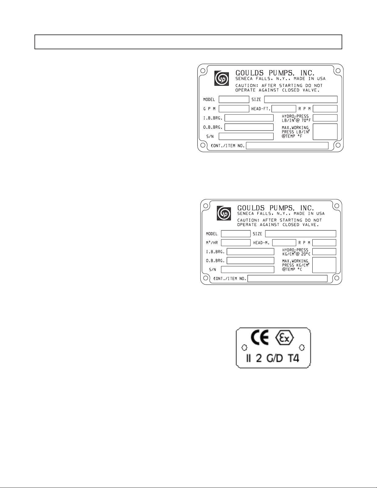
The CE and the Ex designate the ATEX compliance. The code directly below these symbols reads as follows:
II = Group 2
2 = Category 2
G/D = Gas and Dust present
T4 = Temperature class, can be T1 to T6 (see Table 1)
Table 1
Max permissible
surface temperature
Code
T1 842 (450) 700 (372)
T2 572 (300) 530 (277)
T3 392 (200) 350 (177)
T4 275 (135) 235 (113)
T5 212 (100) Option not available
T6 185 (85) Option not available
o
F (oC)
The code classification marked on the equipment must be in accordance with the specified area where the
equipment will be installed. If it is not, do not operate the equipment and contact your ITT Goulds Pumps sales
representative before proceeding.
Max permissible
liquid temperature
o
F (oC)
S-7
Page 12
PARTS
The use of genuine Goulds parts will provide the safest and
most reliable operation of your pump. ITT Goulds Pumps ISO
certification and quality control procedures ensure the parts are
manufactured to the highest quality and safety levels.
Please contact your local Goulds representative for details on
genuine Goulds parts.
S-8
Page 13

GENERAL INFORMATION
PUMP DESCRIPTION ...........................13
NAMEPLATE INFORMATION .....................14
RECEIVING THE PUMP .........................15
Storage Requirements ..........................15
Handling .................................15
PUMP DESCRIPTION
2
The Model 3910 is a vertical bearing frame in-line
centrifugal pump that meets the requirements of API
Standard 610 11th Edition (ISO 13709).
The model is based
pump sizes.
Casing - The casing is a vertical in-line mounted design.
The gasket is fully confined. ANSI Class 300 raised face
serrated flanges are standard; ANSI Class 300 flat face
serrated and ring joint flanges are available.
Impeller - The impeller is fully enclosed and key driven by
the shaft. An impeller nut with locking set screw prevents
axial movement.
Seal Chamber Cover - The Model 3910 seal chamber
cover meets API 682 2nd Edition dimensions for improved
performance of mechanical seals.
on 5 power ends and 27 hydraulic
Power End - Regreasable bearings are standard. The
power end is sealed with labyrinth seals. Pure oil mist
lubrication is optional. Some modifications are required to
convert from grease to oil mist.
Shaft - The standard shaft is machined and ground to
comply with API 610 11th Edition (ISO 13709) criteria.
Bearings - The inboard (radial) bearing carries only radial
load; it is free to float axially in the frame. The outboard
(thrust) bearing is shouldered and locked to the shaft and
retained in the bearing frame to enable it to carry radial and
thrust loads. All fits are precision machined to industry
standards. The inboard bearing is a single row deep groove
ball bearing. The outboard bearing is a duplex angular
contact bearing, which uses a pair of single row angular
contact ball bearings mounted back-to-back.
Motor Support - The fabricated steel motor support is
designed to support the driver and to provide ample access
to both the seal piping and the coupling.
Direction of Rotation - Counterclockwise (left hand) as
viewed from the driver, looking at the pump shaft.
3910-11th IOM 5/08 13
Page 14
NAMEPLATE INFORMATION
Every pump has a Goulds nameplate that provides
information about the pump. The nameplate is located on
the pump casing.
Special tags which provide additional information
(mechanical seal data, etc.) and special tagging required by
customers are located on the pump casing or on the bearing
frame.
The standard nameplate provides information about the
pump’s size, rating, bearings, serial number, hydrostatic
test pressure of pressure containment parts, maximum
allowable working pressure at designated temperature and
construction / customer’s item number. Rating and
hydrostatic test pressure are expressed in English units.
Note the format of pump size: Discharge x Suction Nominal Impeller Diameter in inches, for example, 2x3-13
(Fig. 1A).
The standard nameplate is also available in a version which
expresses the rating and hydrostatic test pressure in metric
units (Fig. 1B).
When ordering spare parts you will need to identify pump
model, size, serial number, and the item number of required
parts. Pump information can be taken from the Goulds
nameplate. Item numbers can be found in this manual.
Fig. 1A
If applicable, your pump unit may have the ATEX tag
affixed to the pump and/or baseplate (Fig. 2). See the
Safety section for a description of the symbols and codes.
Fig. 1B
Fig. 2
14 3910-11th IOM 5/08
Page 15
RECEIVING THE PUMP
Inspect the pump as soon as it is received. Carefully check
that everything is in good order. Make notes of damaged or
missing items on the receipt and freight bill. File any claims
with the transportation company as soon as possible.
STORAGE REQUIREMENTS
Short Term (Less than 6 months) Goulds normalpackaging
procedure is designed to protect the pump during shipping. Upon
receipt, store in a covered and dry location.
Long Term (More than 6 months) Preservative treatment
of bearings and machined surfaces will be required. Rotate
shaft several times every 3 months. Refer to driver and
coupling manufacturers for their long term storage
procedures. Store in a covered and dry location.
NOTE: Long term storage treatment may be
purchased with initial pump order.
HANDLING
! WARNING
s
Pump and components are heavy. Failure to properly
lift and support equipment could result in serious
physical injury, or damage to pumps.
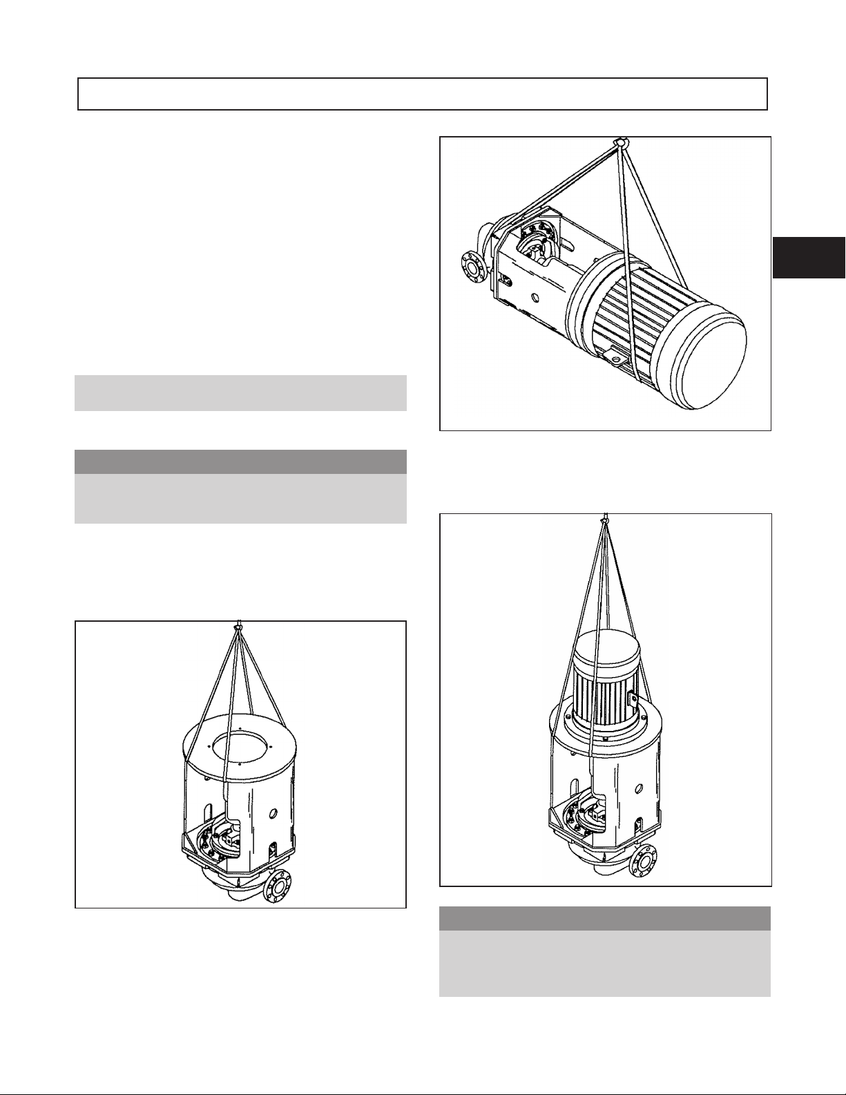
Use care when moving pumps. Lifting equipment must be
able to adequately support the entire assembly. Hoist bare
pump using suitable hooks through the holes in the frame
mounted support or suitable slings through the large
openings in the casing mounted support (Fig. 3).
2
Fig. 4
Or with hooks through the holes in the frame mounted
support or with slings through the large openings in the
casing mounted support.
Fig. 3
! WARNING
Units with drivers mounted are moved with slings under
the pump casing and driver (Figs. 4 and 5).
3910-11th IOM 5/08 15
s
Units with drivers mounted can be top heavy. Driver
weight could cause the assembled unit to overturn and
could result in serious physical injury, or damage to
pumps.
Fig. 5
Page 16

16 3910-11th IOM 5/08
Page 17
INSTALLATION
GENERAL..................................17
SITE/FOUNDATION............................17
ALIGNMENT AND ALIGNMENT CRITERIA .............18
General Considerations..........................18
Alignment Criteria ............................18
ALIGNMENT TROUBLESHOOTING ..................18
PIPING....................................19
Suction Piping ..............................19
Discharge Piping .............................20
Bypass Piping ..............................20
Auxiliary Piping .............................20
Final Piping Check ............................20
Equipment that will operate in a potentially explosive environment must be installed in accordance with the
!
following instructions.
GENERAL
3
Procedures for installation described within this section are
general in nature. It is assumed that the installer has a basic
knowledge of acceptable methods. More detailed
procedures are described in various publications,
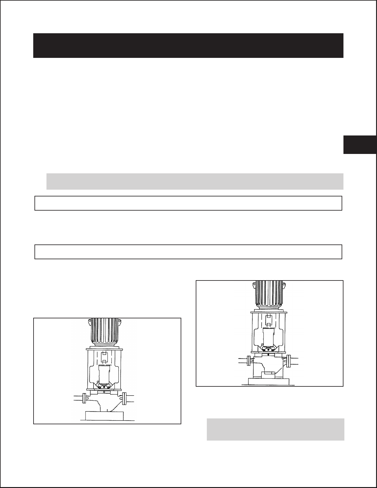
SITE/FOUNDATION
A pump should be located near the supply of liquid and
have adequate space for operation, maintenance, and
inspection. Be sure to allow for crane or hoist service.
Model 3910 in-line pumps are designed to be mounted
directly in the piping. The pump casing has a flat base
which may be mounted on a concrete foundation which has
been poured on a solid footing.
including API Recommended Practice 686/ PIP (Process
Industry Practices) REIE 686, “Recommended Practices
for Machinery Installation and Installation Design.”
Optional casing supports, which provide additional
stability, are also available (Fig. 7).
Fig. 7
If it is intended that the piping support the pumping unit,
piping supports should be properly designed to
accommodate the weight of the pumping unit.
Fig. 6
The foundation must be able to absorb any vibration and to
form a permanent, rigid support for the pumping unit
(Fig. 6). Goulds recommends this mounting method.
3910-11th IOM 5/08 17
All equipment being installed must be properly
!
grounded to prevent unexpected static electric
discharge.
Page 18
ALIGNMENT AND ALIGNMENT CRITERIA
Alignment procedures must be followed to prevent
!
unintended contact of rotating parts. Follow
coupling manufacturer's installation and operation
procedures.
GENERAL CONSIDERATIONS
! WARNING
s
Before beginning any alignment procedure, make sure
driver power is locked out. Failure to lock out driver
power will result in serious physical injury.
To remove coupling guard, refer to coupling guard
installation and disassembly instructions in Appendix I.
The times at which alignment is checked and adjusted are:
Initial Alignment (Cold Alignment) is done prior to
operation when the pump and the driver are at ambient
temperatures.
Final Alignment (Hot Alignment) is done after operation
when the pump and driver are at operating temperatures.
After First Run - To obtain correct alignment when
•
both pump and driver are at operating temperature.
Thereafter, alignment should be checked periodically
in accordance with plant operating procedures.
NOTE: Alignment check must be made if process
temperature changes, piping changes and/or pump
service is performed.
Alignment is achieved by adding or removing shims from
under the flange of the driver and/or shifting driver
horizontally as needed.
NOTE: Proper alignment is the responsibility of the
installer and user of the unit.
Accurate alignment of the equipment must be attained.
Trouble-free operation can be accomplished by achieving
alignment within the levels specified in the following
section.
Three common alignment methods are utilized:
Reverse Dial Indicator method is most common.
•
Laser method is similar to reverse dial indicator
•
method, but uses a laser to obtain the necessary measurements.
Dial Indicator (rim-and-face) method.
•
Follow alignment equipment manufacturer's procedures
when utilizing reverse dial indicator or laser methods. A
detailed procedure for alignment using the dial indicator
(rim-and-face) method is included as Appendix II.
ALIGNMENT CRITERIA
Good alignment is attained when readings as specified in this
section have been achieved with pump and driver at operating
temperatures (final alignment).
Table 2 shows maximum allowable Total Indicator Reading
(T.I.R.) for parallel and angular misalignment.
Table 2
Maximum Allowable
Parallel and Angular Misalignment
Maximum Allowable Misalignment
Group
All
Parallel Angular
0.05 mm
(.002 in.)
[0.125 mm/cm (.0005 in. /in.)
0.03 degrees
of coupling face diameter]
ALIGNMENT TROUBLESHOOTING
Problem Probable Cause Remedy
Cannot obtain horizontal (Side-to-Side)
alignment, angular or parallel
Driver flange bolt bound
18 3910-11th IOM 5/08
Loosen motor support hold down bolts and
slide motor support and driver until horizontal alignment is achieved.
Page 19
PIPING
Guidelines for piping are given in the “Hydraulic Institute
Standards,” available from:
Hydraulic Institute
9 Sylvan Way
Parsippany, NJ 07054
and in API RP 686, and must be reviewed prior to pump
installation.
! WARNING
s
Never draw piping into place by forcing at the flanged
connections of the pump. This may impose dangerous
strains on the unit and cause misalignment between
pump and driver. Pipe strain will adversely affect the
operation of the pump resulting in physical injury and
damage to the equipment.
Flange loads from the piping system, including
!
those from thermal expansion of the piping, must
not exceed the limits of the pump. Casing deformation can result in contact with rotating parts which
can result in excess heat generation, sparks and
premature failure.
1. Piping runs should be as short as possible to minimize
friction losses.
2. It is suggested that expansion loops be properly
designed and installed in suction and/or discharge lines
when handling liquids at elevated tempera- tures, so
thermal expansion of piping will not draw pump out of
alignment.
3. The piping should be arranged to allow pump flushing
prior to removal of the unit on services handling
hazardous liquids.
4. Carefully clean all pipe parts, valves and fittings, and
pump branches prior to assembly.
5. All piping must be supported independently of, and
line up naturally with, the pump flanges. Table 2
shows piping flange alignment criteria.
Bottom of casing should be supported by a solid
6.
foundation or casing feet should be used.
SUCTION PIPING
$
NPSHAmust always exceed NPSHRas shown on
Goulds performance curves received with order.
(Reference Hydraulic Institute for NPSH and pipe
friction values needed to evaluate suction piping).
Properly designed and installed suction piping is a necessity for
trouble-free pump operation. Suction piping should be flushed
BEFORE connection to the pump.
1. Use of elbows close to the pump suction flange should
be avoided. There should be a minimum of two (2)
pipe diameters of straight pipe [five (5) pipe diameters
is preferred] between the elbow and suction inlet.
Where used, elbows should be long radius.
2. Use suction pipe one (1) or two (2) sizes larger than
the pump suction, with a reducer at the suction flange.
Suction piping should never be of smaller diameter
than the pump suction.
3. Reducers, if used, should be eccentric and located at
the pump suction flange with sloping side down.
$
Pump must never be throttled on suction side.
4. A suction screen should be installed prior to initial
start-up and when suction system has been opened for
work. The screen should be of the cone type with a
net area equal to at least three (3) times the cross
sectional area of the suction pipe. The mesh of the
screen should be sized to prevent particles larger than
1.6 mm (1/16 in.) from entering the pump and should
be installed in a spool piece to allow removal for
cleaning. The screen should remain in the system until
periodic inspection shows system is clean.
CAUTION
CAUTION
3
Table 4
Piping Flange Alignment
5. Separate suction lines are recommended when more
than one pump is operating from the same source of
supply.
Type Criteria
Axial
Parallel
Concentric Flange bolts should easily install by hand.
In no case should loads on the pump flanges exceed the
limits stated in API Standard 610, 11th Edition (ISO
13709).
3910-11th IOM 5/08 19
Flange gasket thickness ± 0.8 mm (.03 in.).
0.001 mm/mm (.001 in./in.) of flange diameter
to a maximum of 0.8 mm (.03 in.).
Suction Lift Conditions
1. Suction pipe must be free from air pockets.
2. Suction piping must slope upwards to pump.
3. All joints must be air tight.
4. A means of priming the pump must be provided.
Page 20

Suction Head/Flooded Suction Conditions
1. An isolation valve should be installed in the suction
line at least two (2) pipe diameters from the pump
suction to permit closing of the line for pump
inspection and maintenance.
2. Keep suction pipe free from air pockets.
3. Piping should be level or slope gradually downward
from the source of supply.
4. No portion of the piping should extend below pump
suction flange.
5. The size of entrance from supply should be one (1) or
two (2) sizes larger than the suction pipe.
6. The suction pipe must be adequately submerged below
the liquid surface to prevent vortices and air
entrainment at the supply.
DISCHARGE PIPING
Properly designed and installed discharge piping is a
necessity for trouble-free pump operation. Discharge
piping should be flushed BEFORE connection to the pump.
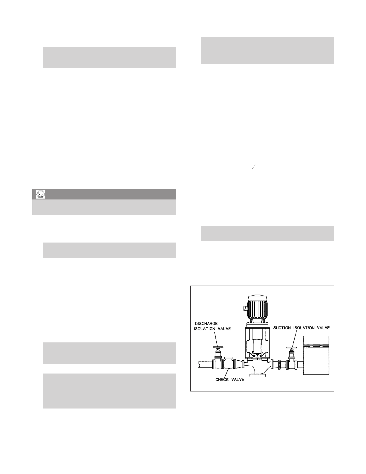
1. Isolation and check valves should be installed in
discharge line. Locate the check valve between
isolation valve and pump; this will permit inspection of
the check valve. The isolation valve is required for
priming, regulation of flow, and for inspection and
maintenance of pump. The check valve prevents pump
or seal damage due to reverse flow through the pump
when the driver is turned off.
2. Increasers, if used, should be placed between pump
and check valves.
3. Cushioning devices should be used to protect the pump
from surges and water hammer if quick-closing valves
are installed in system.
BYPASS PIPING
Systems that require operation at reduced flows for
prolonged periods should be provided with a bypass line
connected from the discharge side (before any valves) to
the source of suction.
A minimum flow orifice can be sized and installed in
bypass line to preclude bypassing excessive flows. Consult
nearest sales office or factory for assistance in sizing
orifice.
An automatic recirculation control valve and/or solenoid
operated valve should be considered if a constant bypass
(i.e. orifice) is not possible.
AUXILIARY PIPING
The mechanical seal must have an appropriate seal
!
flush system. Failure to do so will result in excess heat
generation and seal failure.
Cooling systems such as those for bearing
!
lubrication, mechanical seal systems, etc., where
provided, must be operating properly to prevent
excess heat generation, sparks, and premature
failure.
Sealing systems that are not self purging or self
!
venting, such as plan 23, require manual venting
prior to operation. Failure to do so will result in
excess heat generation and seal failure.
Auxiliary piping may be required for seal chamber cover
cooling, mechanical seal flush or other special features
supplied with the pump. Consult pump data sheet for
specific auxiliary piping recommendations.
If seal chamber cover cooling is required, follow guidelines
listed below.
1. Flows of 4 l/min. (1 GPM) will generally satisfy
cooling requirements.
2. Cooling water pressure should not exceed
7.0 kg/cm
2
(100 psig).
FINAL PIPING CHECK
After connecting the piping to pump:
The Preventive Maintenance section must be
!
adhered to in order to keep the applicable ATEX
classification of the equipment. Failure to follow
these procedures will void the ATEX classification
for the equipment.
Check alignment, per alignment criteria outlined
!
previously, to determine if pipe strain has affected
alignment. If pipe strain exists, correct piping.
20 3910-11th IOM 5/08
Page 21
OPERATION
PREPARATION FOR START-UP ....................21
Checking Rotation ............................21
Coupling Pump and Driver ........................21
Lubricating Bearings ...........................22
Shaft Sealing ...............................22
Priming Pump ..............................22
Start-up Precautions ...........................23
STARTING PUMP .............................24
OPERATION ................................24
General Considerations..........................24
Operational Checks............................24
Operating at Reduced Capacity .....................25
Operating Under Freezing Conditions ..................25
SHUTDOWN ................................25
FINAL ALIGNMENT ...........................25
PREPARATION FOR START-UP
4
When installation in a potentially explosive
!
environment, ensure that the motor is properly
certified.
CHECKING ROTATION
$
Serious damage may result if pump is run in the
wrong rotation.
1. Lock out power to driver.
s
! WARNING
Lock out driver power to prevent accidental start-up
and physical injury.
2. Make sure coupling hubs are securely fastened
to shafts.
! WARNING
s
Do NOT jog a coupled pump.
NOTE: Pump is shipped with coupling spacer
removed.
3. Unlock driver power.
4. Make sure everyone is clear. Jog driver just long enough to
determine direction of rotation. Rotation must correspond
to arrow on bearing frame.
CAUTION
5. Lock out power to driver.
COUPLING PUMP AND DRIVER
! WARNING
s
Lock out driver power to prevent accidental rotation
and physical injury.
The coupling used in an ATEX classified environ-
!
ment must be properly certified.
1. Install and lubricate coupling per manufacturer’s
instructions.
The coupling guard used in an ATEX classified
!
environment must be constructed from a nonsparking material.
2. Install coupling guard. Refer to coupling guard
installation instructions in Appendix I.
! WARNING
s
Never operate a pump without coupling guard properly
installed. Refer to Appendix I for coupling guard
installation instructions. Personal injury will occur if
pump is run without coupling guard.
3910-11th IOM 5/08 21
Page 22
LUBRICATING BEARINGS
Bearings musts be lubricated properly in order to
!
prevent excess heat generation, sparks and
premature failure.
Grease Lubrication
Greased lubricated ball bearings are standard on the Model
3910 units.
Sealing systems that are not self purging or self
!
venting, such as plan 23, require manual venting
prior to operation. Failure to do so will result in
excess heat generation and seal failure.
For satisfactory operation, there must be a liquid film
between seal faces to lubricate them. Refer to seal
manufacturer’s drawing for location of taps. Some methods
which may be used to flush/cool the seal are:
The bearings are greased at the factory.
See Preventive Maintenance section for lubrication
recommendations.
Pure Oil Mist Lubrication
Pure oil mist is an optional feature for the Model 3910.
Follow oil mist generator manufacturer’s instructions. The
inlet and outlet connections are located on the side of the
bearing frame.
See Preventive Maintenance section for lubrication
recommendations and connection locations.
! WARNING
s
Operation of the unit without proper lubrication will
cause bearing failure and pump seizure.
SHAFT SEALING WITH
MECHANICAL SEAL
The mechanical seal used in an ATEX classified
!
environment must be properly certified.
Pumps may be shipped with or without mechanical seal
installed. Cartridge type mechanical seals are commonly
used for this model. Cartridge seals are preset at the seal
manufacturer’s facility and require no field settings.
Cartridge seals installed by the user require disengagement
of the holding clips prior to operation, allowing the seal to
slide into place. If the seal has been installed in the pump
by Goulds, these clips have already been disengaged. For
other types of mechanical seals, refer to the seal
manufacturer’s instructions for installation and setting.
Product Flushing - In this arrangement, the pumpage is
•
piped from the casing (and cooled in an external heat
exchanger when required) then injected into seal
chamber.
External Flush - A clean, cool compatible liquid is
•
injected from an outside source directly into seal
chamber. Flushing liquid must be at a pressure 0.35-1.05
2
kg/cm
rate should be 2-8 l/min. (
Other methods may be used which make use of multiple
•
gland connections and/or seal chamber connections.
Refer to documentation supplied with the pump,
mechanical seal reference drawing, and piping diagrams.
(5-15 psi) greater than seal chamber pressure. Injection
1
-2 GPM).
2
PRIMING PUMP
Pumps must be fully primed at all times during
!
operation.
Never start the pump until it has been properly primed.
Several different methods of priming can be used, depending
upon type of installation and service involved.
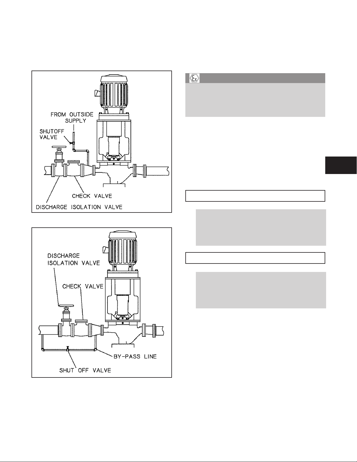
Suction Supply Above Pump
1. Slowly open the suction valve (Fig. 8).
Connection of Sealing Liquid
The mechanical seal must have an appropriate seal
!
flush system. Failure to do so will result in excess heat
generation and seal failure.
Cooling systems such as those for bearing
!
lubrication, mechanical seal systems, etc., where
provided, must be operating properly to prevent
excess heat generation, sparks, and premature
failure.
2. Open air vents on the suction and discharge piping, casing,
seal chamber, and seal piping, if provided, until all air is
vented and only liquid flows out.
3. Close the vents.
22 3910-11th IOM 5/08
Fig. 8
Page 23
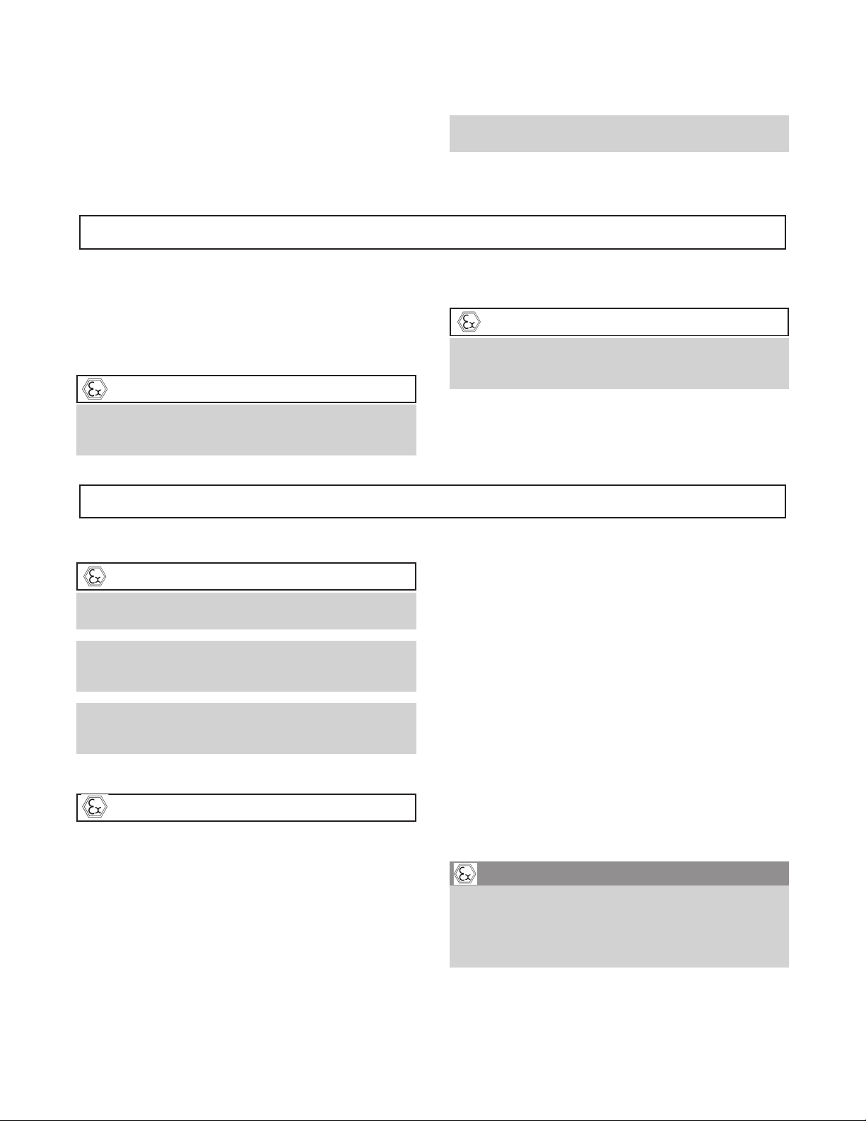
Suction Supply Below Pump
A foot valve and outside source of liquid may be used to
prime the pump. Outside source of liquid can come from a
priming pump pressurized discharge line, or other supply
(Fig. 9 and 10).
1. Close discharge valve and open air vents in suction
and discharge piping, casing, seal chamber, and seal
piping, if provided.
2. Open valve in outside supply line until all air is vented
and only liquid flows out.
! WARNING
s
When handling hazardous and/or toxic fluids, proper
personal protective equipment is required. If pump is
being drained, precautions must be taken to prevent
physical injury. Pumpage must be handled and disposed of in conformance with applicable regulations.
3. Close the vents and then the outside supply line.
Other Methods of Priming Pump
Priming by ejector.
•
Fig. 9
Priming by automatic priming pump.
•
START-UP PRECAUTIONS
$
Ensure that pump and systems are free of foreign
!
objects before operating and that objects cannot
enter the pump during operation. Foreign objects in
the pumpage or piping system can cause blockage of
flow which can result in excess heat generation,
sparks, and premature failure.
$
A build up of gases within the pump, sealing system
!
and or process piping system may result in an
explosive environment within the pump or process
piping system. Ensure process piping system, pump,
and sealing system are properly vented prior to
operation.
1. All equipment and personal safety related devices and
controls must be installed and operating properly.
2. To prevent premature pump failure at initial start-up
due to dirt or debris in the pipe system, ensure the
pump can be run continuously at full speed and flow
for 2 to 3 hours.
CAUTION
CAUTION
4
3. Variable speed drivers should be brought to rated
Fig. 10
3910-11th IOM 5/08 23
speed as quickly as possible.
4. Variable speed drivers should not be adjusted or
checked for speed governor or overspeed trip settings
while coupled to the pump at initial start-up. If
settings have not been verified, uncouple the unit and
refer to driver manufacturer’s instructions for
assistance.
Page 24
5. Running a new or rebuilt pump at slow speeds may not
provide enough flow to adequately flush and cool the
wear ring and seal chamber cover bushing.
6. Pumpage temperatures in excess of 93° C (200° F) will
require warm-up of pump prior to operation. Circulate a
small amount of pumpage through the pump until the
STARTING PUMP
casing temperature is within 56° C (100° F) of the
pumpage temperature and evenly heated.
NOTE: Warm-up rate should not exceed 1.4° C
(2.5° F) per minute.
1. Make sure suction valve and any recirculation or
cooling lines are open.
2. Fully close or partially open discharge valve as
dictated by system conditions.
3. Start driver.
$
Immediately observe pressure gauges. If discharge
pressure is not quickly attained, stop driver, reprime,
and attempt to restart.
CAUTION
OPERATION
GENERAL CONSIDERATIONS
$
Always vary capacity with regulating valve in the discharge
line. NEVER throttle flow from the suction side.
Driver may overload if the pumpage specific gravity
(density) is greater than originally assumed, or the
rated flow rate is exceeded.
Always operate the pump at or near the rated
conditions to prevent damage resulting from cavitation
or recirculation.
OPERATIONAL CHECKS
$
The following are minimum operational checks for the
pump only. Consult driver and auxiliary equipment
manufacturers’ literature for additional information.
1. On grease lubricated units, remove grease relief plugs
to verify that grease is present. Replace plugs.
2. On pure oil mist lubricated units, remove viewing port
plugs and assure oil mist is flowing properly. Replace
plugs.
CAUTION
CAUTION
4. Slowly open discharge valve until the desired flow is
obtained.
CAUTION
$
Observe pump for vibration levels, bearing temperature, and excessive noise. If normal levels are
exceeded, shut down and resolve.
3. Check bearing temperatures using a pyrometer or other
accurate temperature measuring device. Monitor
bearing temperature frequently during initial operation
to determine if a bearing problem exists as well as to
establish normal bearing operating temperature.
4. On units equipped with auxiliary piping, assure that
proper flows have been established and that equipment
is operating properly.
5. Establish baseline vibration readings to determine
normal running conditions. If it is determined that the
unit is running rough, consult factory.
6. Monitor all gauges to ensure pump is running at or
near rating and that suction screen (when used) is not
clogged.
!
OPERATING AT REDUCED
CAPACITY
! WARNING
s
Do NOT operate pump below minimum rated flows or
with discharge valve closed. These conditions may
create an explosive hazard due to vaporization of
pumpage and can quickly lead to pump failure and
physical injury.
24 3910-11th IOM 5/08
Page 25

$
Damage occurs from:
1. Increased vibration levels - Affects bearings, seal
chambers, and mechanical seals.
2. Increased radial load - Increases stress on shaft and
bearings.
3. Heat build up - Vaporization causes rotating parts to
score or seize.
4. Cavitation - Increases damage to internal surfaces of
pump.
CAUTION
SHUTDOWN
1. Slowly close discharge valve.
2. Shut down and lock out driver to prevent
accidental rotation.
OPERATING UNDER FREEZING
CONDITIONS
Exposure to freezing conditions while pump is idle could
cause liquid to freeze and damage the pump.
Liquid inside pump should be drained. Liquid inside
auxiliary piping, if supplied, should also be drained.
s
! WARNING
When handling hazardous and/or toxic fluids, proper
personal protective equipment is required. If pump is
being drained, precautions must be taken to prevent
physical injury. Pumpage must be handled and
disposed of in conformance with applicable
regulations.
4
FINAL ALIGNMENT
Alignment procedures must be followed to prevent
!
unintended contact of rotating parts. Follow
coupling manufacturer’s installation and operation
procedures.
1. Run the unit under actual operating conditions for a
sufficient length of time to bring the pump and driver and
associated systems to operating temperature.
2. Shut down and lock out driver as described above.
! WARNING
s
Before beginning any alignment procedure, make sure
driver power is locked out. Failure to lock out driver
power will result in serious physical injury.
3. Remove coupling guard. Refer to coupling guard
installation and disassembly instructions in Appendix I.
4. Check alignment while unit is still hot per alignment
criteria in the Installation section.
5. Reinstall coupling guard. Refer to coupling guard
installation and disassembly instructions in Appendix I.
3910-11th IOM 5/08 25
Page 26

26 3910-11th IOM 5/08
Page 27

PREVENTIVE MAINTENANCE
GENERAL COMMENTS .........................27
MAINTENANCE SCHEDULE ......................27
Routine Maintenance ...........................27
Routine Inspections............................27
3 Month Inspections ...........................27
Annual Inspections ............................27
Inspection Intervals............................28
MAINTENANCE OF BEARINGS ....................28
Grease Lubricated Bearings .......................28
Pure Oil Mist Lubricated Bearings (Optional) ..............28
MAINTENANCE OF SHAFT SEALS ..................29
TROUBLESHOOTING ..........................30
GENERAL COMMENTS
A routine maintenance program can extend the life of your pump. Well maintained equipment
will last longer and require fewer repairs. You should keep maintenance records as this will help
pinpoint potential causes of problems.
The Preventive Maintenance section must be adhered to in order to keep the applicable ATEX classification of the
!
equipment. Failure to follow these procedures will void the ATEX classification for the equipment.
MAINTENANCE SCHEDULE
ROUTINE MAINTENANCE
Bearing lubrication
•
Seal monitoring
•
Vibration analysis
•
Discharge pressure monitoring
•
Temperature monitoring
•
ROUTINE INSPECTIONS
3 MONTH INSPECTIONS
Check foundation.
•
If pump has been left idle, check mechanical seal.
•
Repair or replace if required.
Pump should be re-greased at least every 3 months
•
(2000 hours) or more often if there are any adverse
atmospheric conditions or other conditions which
might contaminate or break down the grease.
Check shaft alignment and realign if required.
•
5
Check for unusual noise, vibration and bearing
•
temperatures.
Inspect pump and piping for leaks.
•
Check seal chamber for leakage.
•
3910-11th IOM 5/08 27
ANNUAL INSPECTIONS
Check pump capacity, pressure and power. If pump
•
performance does not satisfy your process requirements,
and process requirements have not changed, pump
should be disassembled, inspected, and worn parts
should be replaced. Otherwise, a system inspection
should be done.
Page 28

INSPECTION INTERVALS
Inspection intervals should be shortened appropriately
•
if the pumpage is abrasive and/or corrosive,
or if the enviornment is classified as potentially
!
explosive.
MAINTENANCE OF BEARINGS
Do not insulate bearing housings as this can result
!
in excess heat generation, sparks, and premature
failure.
Service temperature in an ATEX classified environ-
!
ment is limited to the area classification specified on
the ATEX tag affixed to the pump (reference Table 1
in the Safety section for ATEX classifications).
GREASE LUBRICATED BEARINGS
Grease lubricated bearings are pre-lubricated at the
factory. Regrease bearings every 2000 operating hours or
3 months, whichever occurs first.
NOTE: The bearing temperature usually rises after
regreasing due to an excess supply of grease. Temperatures will return to normal after pump has run and
purged the excess from the bearings, usually two to
four hours. Grease relief plugs should be removed
during this period, and replaced when temperature
has stabilized.
For most operating conditions a lithium based mineral oil
grease of NLGI consistency number 2 is recommended.
This grease is acceptable for bearing temperatures of -15°C
to 110°C (5°F ro 230°F).
Bearing temperatures are generally about 20°F (18°C)
higher than bearing housing outer surface temperature.
Regrease Procedure
NOTE: When regreasing there is danger of impurities
entering the bearing housing. The grease container,
the greasing device, and fittings must be clean.
1. Wipe dirt from both grease fittings (Fig. 11).
2. Remove two grease relief plugs from side of frame
opposite grease fittings.
3. Fill both grease cavities through grease fittings with
recommended grease until fresh grease comes out of
the relief holes. Reinstall grease relief plugs until
immediately prior to starting pump.
Some acceptable greases are:
NLGI Consistency 2
Exxon Unirex N2
Mobil Mobilux EP2
Sunoco Multipurpose EP
SKF LGMT 2
! CAUTION
$
Never mix greases of different consistency (NLGI 1 or
3 with NLGI 2) or different thickener. For example,
never mix a lithium base grease with a polyurea base
grease.
NOTE: If it is necessary to change grease type or
consistency, the pump must be disassembled and the
old grease removed from the bearings.
PURE OIL MIST LUBRICATED
BEARINGS (OPTIONAL)
! WARNING
s
Pumps are shipped without oil. Oil mist lubricated
bearings must be lubricated at the job site.
1. Follow oil mist system supplier’s instructions.
Fig. 11
2. Connect oil mist supply lines to upper and center
tapped connection.
28 3910-11th IOM 5/08
Page 29

3. Connect drain line to bottom tapped connection
(Fig. 12).
Oil mist lubrication is required above pumpage temperature
of 232°C (450°F), but may be used at lower temperature.
Fig. 12
A high quality turbine oil with rust and oxidation inhibitors
should be used. For the majority of operational conditions,
bearing temperatures will run between 50°C (120°F) and
82°C (180°F). In this range, an oil of ISO viscosity grade
68 at 40°C (100°F) is recommended. If bearing temperatures exceed 82°C (180°F), use ISO viscosity grade 100.
Some acceptable oils are:
Exxon Teresstic EP68
Mobil Mobil DTE 26 300 SSU
@ 40°C (100°F)
Sunoco Sunvis 968
Royal Purpal SYNFILM ISO VG 68
Synthetic Lube
MAINTENANCE OF SHAFT SEALS
The mechanical seal used in an ATEX classified
!
environment must be properly certified.
When mechanical seals are furnished by Goulds, a
manufacturer’s reference drawing is supplied with the data
package. This drawing should be kept for future use when
performing maintenance and adjusting the seal. The seal
drawing will also specify required flush liquid and
attachment points. The seal and all flush piping must be
checked and installed as needed prior to starting the pump.
The life of a mechanical seal depends on various factors
such as cleanliness of the liquid handled and its lubricating
properties. Due to the diversity of operating conditions it is,
however, not possible to give definite indications as to its
life.
! WARNING
s
NEVER operate the pump without liquid supplied to the
mechanical seal. Running a mechanical seal dry, even
for a few seconds, can cause seal damage and must be
avoided. Physical injury can occur if mechanical seal
fails.
The mechanical seal must have an appropriate seal
!
flush system. Failure to do so will result in excess heat
generation and seal failure.
Cooling systems such as those for bearing
!
lubrication, mechanical seal systems, etc., where
provided, must be operating properly to prevent
excess heat generation, sparks and premature
failure.
Sealing systems that are not self purging or self
!
venting, such as plan 23, require manual venting
prior to operation. Failure to do so will result in
excess heat generation and seal failure.
5
3910-11th IOM 5/08 29
Page 30

TROUBLESHOOTING
Problem Probable Cause Remedy
Check that pump and suction line are full of liquid.
Reprime pump.
Consult factory for proper depth.
Use baffle to eliminate vort ices.
Ensure that suction line shutoff valve is fully open
and line is unobstructed.
Increase suction head.
Change rotation to concur with direction
indicated by arrow on bearing frame.
Assure uniform contact of pump and/or supports
with foundation.
Anchor per Hydraulic Institute Standards/
API RP 686 recommendations.
Consult factory.
Install throttle valve.
Cut impeller.
No liquid delivered.
Pump not producing
rated flow or head.
Pump starts then stops
pumping.
Bearings run hot.
Pump is noisy or
vibrates.
Excessive leakage from
stuffing box.
Motor requires
excessive power.
Pump not primed.
Suction line clogged. Remove obstructions.
Impeller clogged with foreign material. Back flush pump to clean impeller.
Foot valve or suction pipe opening not
sufficiently submerged.
Suction lift too high. Reduce suction lift.
Air leak thru gasket. Replace gasket.
Air leak thru seal chamber. Replace or readjust mechanical seal.
Impeller partly clogged. Back flush pump to clean impeller.
Worn wear rings. Replace defective part as required.
Insufficient suction head.
Worn or broken impeller. Inspect and replace if necessary.
Wrong direction of rotation.
Improperly primed pump. Reprime pump.
Air or vapor pockets in suction line. Rearrange piping to eliminate air pockets.
Air leak in suction line. Repair (plug) leak.
Improper alignment. Re-align pump and driver.
Improper lubrication. Check lubricant for suitability and quantity.
Insufficient cooling liquid. Check cooling system.
Improper pump/driver alignment. Align shafts.
Partly clogged impeller causing imbalance. Backflush pump to clean impeller.
Broken or bent impeller or shaft. Replace as required.
Impeller out of balance. Balance impeller.
Foundation not rigid.
Worn bearings. Replace.
Suction or discharge piping not anchored or properly
supported.
Pump is cavitating. Locate and correct system problem.
Worn mechanical seal parts. Replace mechanical seal.
Overheating mechanical seal. Check lubrication and cooling lines.
Head lower than rating. Pumps too much liquid.
Liquid heavier than expected. Check specific gravity and viscosity.
Rotating parts bind. Check internal wear parts for proper clearances.
30 3910-11th IOM 5/08
Page 31

DISASSEMBLY & REASSEMBLY
REQUIRED TOOLS ............................31
DISASSEMBLY...............................31
INSPECTIONS ...............................36
RENEWAL OF WEAR PARTS ......................41
REASSEMBLY ...............................44
ASSEMBLY TROUBLESHOOTING ...................54
REQUIRED TOOL
Open end wrenches
•
Lifting sling
•
Induction bearing heater
•
Brass drift punch
•
Spanner wrench
•
Allen wrenches
•
Torque wrench with sockets
•
Dial indicator
•
Micrometers (inside and outside)
•
Cleaning agents
•
Feeler gauges
•
DISASSEMBLY
! WARNING
s
Pump components are heavy. Proper methods of lifting
and securing must be employed to avoid physical injury
and/or equipment damage.
! WARNING
s
The Model 3910 may handle hazardous and/or toxic fluids.
Proper personal protection is required. Precautions must be
taken to prevent physical injury. Pumpage must be handled
and disposed of in conformance with applicable
regulations.
NOTE: Before disassembling the pump for overhaul,
ensure all replacement parts are available.
Drill
•
Tap
•
Spanning type puller
•
Soft face hammer
•
Press
•
PREPARATION FOR DISASSEMBLY
1. Shut off all valves controlling flow to and from pump.
! WARNING
s
Operator must be aware of pumpage and safety
precautions to prevent physical injury.
2. Drain liquid from piping; flush pump if necessary.
3. Disconnect all auxiliary piping, tubing and equipment
that will interfere with removal of back pull-out
assembly.
4. Remove coupling guard. Refer to coupling guard
installation and disassembly instructions in Appendix I.
5. Remove coupling spacer. Follow coupling
manufacturer’s instructions for assistance.
6
! WARNING
s
Lock out power supply to driver to prevent accidental
startup and physical injury.
3910-11th IOM 5/08 31
Page 32

REMOVAL OF BACK PULL-OUT
ASSEMBLY
1. Loosen and remove casing stud nuts (425).
2. Separate back pull-out assembly from casing (100) by
tightening jacking bolts (418) provided. Tighten
jacking bolts evenly using alternating pattern (Fig. 13).
NOTE: Penetrating oil may be used if seal chamber
cover to casing joint is excessively corroded.
Fig 14
3. Pull impeller (101) from shaft (122). Use a spanning
type puller if required.
Fig. 13
3. Remove back pull-out assembly using Goulds back
pull-out device or other suitable means. Refer to
instructions in Appendix III.
! WARNING
s
Pump components are heavy. Proper methods of
lifting and securing must be employed to avoid physical
injury and/or equipment damage.
4. Remove and discard casing gasket (351). (Replace this
with new gasket during reassembly.)
5. Secure to prevent movement during transport.
Transport back pull-out assembly to a clean work area
for further disassembly.
6. Support and secure back pull-out assembly firmly to
workbench.
REMOVAL OF IMPELLER
1. Loosen set screw (198A) in end of impeller nut (304)
(Fig. 14).
2. Loosen and remove impeller nut (304).
NOTE: Impeller nut has LEFT HAND threads.
$
When handling the impeller, wear heavy work gloves to
prevent cutting hands on sharp edges.
4. Remove impeller key (178).
CAUTION
REMOVAL OF COUPLING HUB
1. Blue and scribe shaft (122) for relocating coupling hub
during reassembly (Fig. 15).
2. Remove coupling hub.
Fig. 15
REMOVAL OF SEAL CHAMBER
COVER
1. Loosen and remove gland stud nuts (355 )(Fig. 16).
2. Slide cartridge mechanical seal away from seal
chamber cover (184).
3. Install eyebolt in tapped hole provided in seal chamber
cover (184).
4. Rig lifting sling to eyebolt and to overhead lifting
device. Take light strain on sling.
32 3910-11th IOM 5/08
Page 33

5. Loosen and remove seal chamber cover/bearing frame
bolts (370H).
6. Separate seal chamber cover (184) from bearing frame
(228) by tapping on cover flange with a hardwood
block or a soft face hammer.
7. Guide seal chamber cover (184) over end of shaft
(122) once cover releases from bearing frame (228).
!
$
Cartridge mechanical seal may be damaged if cover is
allowed to come in contact with it.
8. Loosen set screws and remove cartridge mechanical
seal from shaft (122).
9. Remove and discard mechanical seal O-ring or gland
gasket (360Q). (Replace this with a new O-ring or
gasket during reassembly.)
CAUTION
REMOVAL OF OPTIONAL WATER
JACKET COVER
1. Suspend seal chamber cover (184) from lifting sling, or
firmly support seal chamber cover in a vertical position
such that one water jacket connection is on the top and
the other is on the bottom.
! WARNING
s
Seal chamber cover must be adequately supported so
that it cannot fall. Personal injury and/or damage to
equipment could occur.
2. Introduce water slowly into the bottom connection
until all air is vented and only water comes out of the
top connection.
! WARNING
s
All air must be vented from water jacket. If all air is
not vented, it can cause water jacket cover (490) to be
propelled from its fit in the seal chamber cover (184).
Personal injury and/or damage to equipment could
occur.
3. Stop introduction of water into water jacket.
4. Seal top connection with plug or other suitable means.
5. Slowly increase water pressure on inlet (bottom)
connection. Water jacket cover (490) should be forced
from its fit in the seal chamber cover (184). Be
prepared to catch water jacket cover.
!
$
Do not exceed 7.0 kg/cm2(100 psig) pressure in water
jacket.
6. Remove and discard outer and inner water jacket cover
O-rings (412S and 497T, respectively) from grooves in
water jacket cover (490). (Replace these with new
O-rings during reassembly.)
CAUTION
6
Fig. 16
3910-11th IOM 5/08 33
Page 34

DISASSEMBLY OF STANDARD
GREASE LUBRICATED POWER END
This section covers disassembly of standard ring oil or
optional purge oil mist lubricated power end. For power
ends with optional features (pure oil mist lubrication,
bearing cooling, etc.), refer to the appropriate section.
1. Loosen and remove thrust bearing end cover/bearing
frame screws (370N).
2. Pry thrust bearing end cover (109A)/INPRO (123A)
with O-ring (412, not shown) out of bearing frame
(228). SA thrust bearing end cover is sealed to the
bearing frame with a gasket (360A) (Fig. 17).
Fig. 17
3. Remove and discard thrust bearing end cover shims
(390C). Replace with new shims during reassembly.
(Not applicable to pumps with SA bearing frame.)
4. Withdraw shaft/bearing assembly carefully from
bearing frame (228).
$
Do NOT remove bearings from shaft unless
they are to be replaced.
5. Bend locking tang of thrust bearing lockwasher (382) from
notch in bearing locknut (136) (Fig. 18).
NOTE: Save bearings for inspection.
6. Loosen and remove thrust bearing locknut (136) and
lockwasher (382).
7. Press or pull duplex thrust bearing (112) from shaft
(122).
8. Remove grease shelf (253) from shaft (122).
9. Press or pull radial bearing (168) from shaft (122).
NOTE: Save bearing for inspection.
10. Loosen and remove radial bearing end cover / bearing
frame screws (370P) (Fig. 19). Omit this step on SA
pumps. Radial INPRO Oil Seal (123) is pressed in
place and sealed with an O-ring (Fig. 20).
11. Remove radial bearing end cover (119A)/ Radial
INPRO (123) with gasket (360) or Radial INPRO
(123) (SA pump only) from bearing frame (228) by
tapping out of fit in frame.
CAUTION
34 3910-11th IOM 5/08
Fig. 18
Page 35

Fig. 19
Fig. 20
12. Remove and discard radial bearing end cover gasket
(360). (Replace this with a new gasket during
reassembly.)
13. Press Radial and Thrust INPRO (123 & 123A) out of
radial (N/A on SA pumps) and Thrust End Covers
(119A & 109A).
DISASSEMBLY OF OPTIONAL PURE
OIL MIST LUBRICATED POWER END
Pure oil mist lubricated power ends are disassembled in the
same manner as grease lubricated power ends. Grease
shelf (253) is not furnished with pure oil mist lubrication.
Disregard any reference to this part.
DISASSEMBLY OF POWER END
WITH OPTIONAL RADIAL HEAT
FLINGER
The radial heat flinger (123B) replaces the standard radial
INPRO (123) and is removed in the same manner except 3
set screws (222) need to be loosened (Fig. 21). Remove
and discard frame / seal chamber cover thermal gasket
(540C) (Fig. 16). (Replace this with a new gasket during
reassembly. Remainder of disassembly is the same as
grease lubrication.
DISASSEMBLY OF POWER END
WITH OPTIONAL AIR COOLING
PACKAGE
1. Loosen radial heat flinger set screw (222) (Fig. 21).
2. Loosen thrust fan set screw (222). SA pumps thrust fan
sits on coupling diameter.
3. Slide thrust fan (123E) off shaft (122).
4. Loosen and remove thrust bearing end cover/bearing
frame screws (370N).
5. Remove thrust fan guard support (234D).
Remainder of disassembly is the same as steps 2-13 of
grease lubrication section.
FINAL DISASSEMBLY
Remove any remaining plugs and fittings.
6
Fig. 21
3910-11th IOM 5/08 35
Page 36

INSPECTIONS
Model 3910 parts must be inspected to the following
criteria before they are reassembled to ensure the pump will
run properly. Any part not meeting the required criteria
should be replaced.
NOTE: Clean parts to remove oil, grease or dirt.
Protect machined surfaces against damage during
cleaning.
CASING (100)
The casing should be inspected for excessive wear,
corrosion or pitting. Areas most susceptible are indicated
by the arrows in Fig. 22. Casing should be repaired or
replaced if it exceeds the following criteria:
1. Localized wearing or grooving greater than 3.2 mm
1
(
in.) deep.
8
2. Pitting greater than 3.2 mm (
3. Irregularities in case gasket seat surface which could
hinder or prevent sealing.
1
in.) deep.
8
Fig. 23
Fig. 22
IMPELLER (101)
1. Inspect impeller vanes for damage. Replace if grooved
deeper than 1.6 mm (
than 0.8 mm (
2. Inspect shrouds for damage. Replace if worn or bent
more than 0.8 mm (
3. Inspect leading and trailing edges of the vanes for pitting,
and erosion or corrosion damage. Replace as in No. 1.
(Area “c” in Fig. 23.)
4. Clean and check impeller bore diameter.
5. Check impeller balance. It should be rebalanced if it
exceeds the criteria of ISO 1940 G1.0.
NOTE: Balancing impellers to ISO 1940 G1.0 requires
extremely accurate tooling and equipment and should
not be attempted unless such tooling and equipment
are available.
1
in.) or if worn evenly more
1
16
in.). (Area “a” in Fig. 23.)
32
1
in.). (Area “b” in Fig. 23.)
32
BALL BEARINGS (112, 168)
1. Ball bearings should be inspected for contamination
and damage. The condition of the bearings will
provide useful information on operating conditions in
the bearing frame (228).
2. Lubricant condition and residue should be noted.
3. Bearing damage should be investigated to determine cause.
If cause is not normal wear, it should be corrected before
pump is returned to service.
NOTE: It is good practice to replace all ball bearings that
have been removed from their shaft fits. Always replace if
they are worn, loose or rough and noisy when rotated.
Replacement bearings must be of proper size and type.
4. Replacement bearings must be the same as, or
equivalent to, those listed in Table 3.
Table 4
Model 3910 Bearings
Radial (Inboard)
Group
SA
SX
MX, LA
XLX
NOTE: Bearing numbers are based on SKF / MRC
designations.
6210 C3Z
6212 C3Z
6213 C3Z
6218 C3Z
6210 C3
6212 C3
6213 C3
6218 C3
Thrust
(Outboard)Grease Oil Mist
7310 BEGAM
7312 BEGAM
7312 BEGAM
7317 BEGAM
36 3910-11th IOM 5/08
Page 37

SHAFT (122)
1. Check bearing fits. If any are outside the tolerance
shown in Tables 5 or 5A, replace the shaft (Fig. 24).
2. Check shaft surface for damage, especially in areas
indicated by arrows in Fig. 24. Replace if damaged
beyond reasonable repair.
Model 3910 Bearing Fits & Tolerances (SI Units)
According to ISO 286 (ANSI/ABMA Standard 7)
Location Description
Shaft O.D.
Interference
Radial
(Inboard)
Thrust
(Outboard)
Bearing I.D.
Frame I.D.
Clearance
Bearing O.D.
Shaft O.D.
Interference
Bearing I.D.
Frame I.D.
Clearance
Bearing O.D.
SA SX MX, LA XLX
50.013 60.015 65.015 90.018
50.002 60.002 65.002 90.003
0.002 0.002 0.002 0.003
0.025 0.030 0.030 0.038
49.988 59.985 64.985 89.980
50.000 60.000 65.000 90.000
90.000 110.000 120.000 160.000
90.022 110.022 120.022 160.025
0.000 0.000 0.000 0.000
0.037 0.037 0.037 0.050
90.000 110.000 120.000 160.000
89.985 110.022 119.985 159.975
50.013 60.015 60.015 85.018
50.002 60.002 60.002 85.003
0.002 0.002 0.002 0.003
0.025 0.030 0.030 0.038
49.998 59.985 59.985 84.980
50.000 60.000 60.000 85.000
110.000 130.000 130.000 180.000
110.022 130.025 130.025 180.025
0.000 0.000 0.000 0.000
0.037 0.043 0.043 0.050
110.000 130.000 130.000 180.000
109.985 129.982 129.982 179.975
Table 5
Group and Dimensions (mm)
3. Check shaft straightness. Use “V” blocks or balance
rollers to support the shaft on bearing fit areas.
Replace shaft if runout exceeds 0.03 mm (.001 in.)
NOTE: Do NOT use shaft centers for runout check as
they may have been damaged when removing bearings
or impeller.
Fig. 24
6
3910-11th IOM 5/08 37
Page 38

Model 3910 Bearing Fits & Tolerances (USA Units)
Location Description
Shaft O.D.
Interference
Radial
(Inboard)
Thrust
(Outboard)
Bearing I.D.
Frame I.D.
Clearance
Bearing O.D.
Shaft O.D.
Interference
Bearing I.D.
Frame I.D.
Clearance
Bearing O.D.
Table 5A
According to ISO 286 (ANSI/ABMA Standard 7)
Group and Dimensions (inches)
SA SX MX, LA XLX
1.9690 2.3628 2.5597 3.5440
1.9686 2.3623 2.5592 3.5434
0.0001 0.0001 0.0001 0.0001
0.0010 0.0012 0.0012 0.0015
1.9680 2.3616 2.5585 3.5425
1.9685 2.3622 2.5591 3.5433
3.5433 4.3307 4.7244 6.2992
3.5442 4.3316 4.7253 6.3002
0.0000 0.0000 0.0000 0.0000
0.0015 0.0015 1.0015 0.0020
3.5483 4.3307 4.7244 6.2992
3.5427 4.3301 4.7238 6.2982
1.9691 2.3628 2.3628 3.3472
1.9686 2.3623 2.3623 3.3466
0.0001 0.0001 0.0001 0.0001
0.0010 0.0012 0.0012 0.0015
1.9680 2.3616 2.3616 3.3457
1.9685 2.3622 2.3622 3.3465
4.3307 5.1181 5.1181 7.0866
4.3315 5.1191 5.1191 7.0876
0.0000 0.0000 0.0000 0.0000
0.0015 0.0017 0.0017 0.0020
4.3307 5.1181 5.1181 7.0866
4.3301 5.1174 5.1174 7.0856
WEAR RINGS (164, 202, 203, 230)
All units are equipped with casing (164), impeller (202 and
203) and seal chamber cover wear rings (230).
When clearances between the rings become excessive,
hydraulic performance decreases substantially.
1. Measure all wear ring diameters (Figs. 25, 26, 27).
2. Calculate diametral wear ring clearances. Minimum
diametral clearances should be as shown in Table 6.
3. Replace wear rings when diametral clearance exceeds
two times the minimum clearance as shown in Table 6
or when the hydraulic performance has decreased to
unacceptable levels. Refer to Renewal of Wear Parts
for replacement instructions for wear rings.
NOTE: For operating temperatures above 260° C
(500° F) and for materials with greater galling
tendencies (e.g. stainless steel), increase diametral
clearance dimensions by 0.13 mm (.005 in.).
38 3910-11th IOM 5/08
Fig. 25
Page 39

Fig. 26
SEAL CHAMBER COVER (184)
Seal chamber cover is available in two versions: one
(optional) has a cooling chamber and water jacket cover
(490) and the other (standard) does not. The (optional)
cooled version is used when elevated pumpage
temperatures are present.
1. Ensure all gasket/O-ring sealing surfaces are clean and
have no damage that would hinder or prevent sealing
(Fig. 28).
2. Ensure all cooling (where applicable), flush and drain
passages are clear.
3. Inspect other surfaces for damage. Replace if worn,
damaged or corroded more than 3.2 mm (
4. Measure inside diameter of seal chamber cover
bushing (125). If the diametral clearance between it
and the impeller hub (101) exceeds 1.20 mm (.047 in.),
one or both parts should be replaced. Refer to
Renewal of Wear Parts for replacement instructions
for seal chamber cover bushing.
1
in.) deep.
8
Fig. 27
Table 6
Minimum Running Clearances
Diameter of
Impeller
Wear Ring
mm in. mm in.
<50 <2.000 0.25 0.010
To to 64.99 2.000 to 2.4999 0.28 0.011
65 to 79.99 2.500 to 2.999
80 to 89.99 3.000 to 3.499
90 to 99.99 3.500 to 3.999
100 to 114.99 4.000 to 4.499
115 to 124.99 4.500 to 4.999
125 to 149.99 5.000 to 5.999
150 to 174.99 6.000 to 6.999
175 to 199.99 7.000 to 7.999
200 to 224.99 8.000 to 8.999
225 to 249.99 9.000 to 9.999
250 to 274.99 10.000 to 10.999
275 to 299.99 10.000 to 11.999
300 to 324.99 12.000 to 12.999
Minimum
Diametral
Clearance
0.30
0.33
0.35
0.38
0.40
0.43
0.45
0.48
0.50
0.53
0.55
0.58
0.60
0.012
0.013
0.014
0.015
0.016
0.017
0.018
0.019
0.020
0.021
0.022
0.023
0.024
6
Fig. 28
3910-11th IOM 5/08 39
Page 40

BEARING FRAME (228)
1. Visually inspect bearing frame for damage and cracks.
2. Check frame inside surfaces for rust, scale or debris.
Remove all loose and foreign material (Fig. 29).
3. Make sure all lubrication passages are clear.
4. Check bearing bores. If any are outside the tolerance
in Table 6, replace the bearing frame.
GASKETS, O-RINGS, SHIMS, AND
SEATS
NOTE: Spiral wound gaskets should not be reused.
1. Replace all gaskets, O-rings and shims at each
overhaul / disassembly.
2. Inspect seats. They must be smooth and free of
physical defects. Skin cut seats in lathe as necessary,
maintaining dimensional relationships with other
surfaces. Replace parts if seats are defective beyond
reasonable repair.
GENERAL
All other parts should be inspected and repaired or
replaced, as appropriate, if inspection indicates continued
use would be harmful to satisfactory and safe pump
operation.
Inspection must include, but not be limited to, the
following:
Fig. 29
CARTRIDGE MECHANICAL SEAL
Refer to mechanial seal manufacturer’s instructions for
assistance.
Cartridge type mechanical seals should be serviced by seal
manufacturer.
COUPLING GUARD
1. Inspect guard for corrosion or other defects.
2. Replace guard or repair.
! WARNING
s
To avoid physical injury, coupling guard must be
installed and must be maintained in first-class
condition.
Bearing End Covers (109A) and (119A)
•
INPROS (123) and (123A)
•
Radial Heat Flinger (123B)*
•
Thrust Fan (123E)*
•
Bearing Locknut (136)
•
Impeller Key (178) and Coupling Key
•
Impeller Nut (304)
•
Bearing Lockwasher (382)
•
Water Jacket Cover (490)*
•
All Nuts, Bolts and Screws
•
* If supplied.
40 3910-11th IOM 5/08
Page 41

RENEWAL OF WEAR PARTS
REPLACEMENT OF SEAL
CHAMBER COVER BUSHING
Seal chamber cover bushing (125) is held in place by a
press fit and locked by three set screws.
Removal of Bushing (125)
1. Remove set screws.
2. Press bushing (125) out of fit toward bearing frame
side of seal chamber cover (184) bore (Fig. 30).
Fig. 30
Installation of Bushing (125)
1. Clean bushing fit in seal chamber cover (184)
thoroughly.
2. Chill new bushing (125) using dry ice or other suitable
chilling substance, and install bushing into fit of cover
(184). Be prepared to tap the bushing in place with a
hardwood block or soft faced hammer (Fig. 31).
! WARNING
s
Dry ice and other chilling substances can cause physical
injury. Contact supplier for information and advice for
proper handling precautions and procedures.
3. Locate, drill and tap three new set screw holes on
impeller side of cover (184) equally spaced between
original set screw holes.
4. Install set screws and upset threads.
REPLACEMENT OF WEAR RINGS
Casing (164), impeller (202 and 203) and seal chamber
cover wear rings (230) are held in place by a press fit and
three set screws (222E and 320).
Removal of Wear Rings (164, 202, 203, 230)
1. Remove set screws (222E and 320).
2. Remove wear rings from casing (100), impeller (101),
and seal chamber cover (184) using suitable pry or
puller to force rings from fits.
Rings may also be machined for removal.
!
$
Excessive machining can damage ring fits and render
parts unusable.
Installation of Wear Rings (164, 202, 203, 230)
1. Clean wear ring seats thoroughly, insuring they are
smooth and free of scratches.
2. Heat new impeller wear rings (202 and 203) to 82° 93° C (180° - 200° F) using a uniform method for
heating (e.g. - oven) and place on impeller (101) wear
ring seats (Fig. 32).
!
$
Use insulated gloves to handle rings. Ringswill be hot
and can cause physical injury.
CAUTION
CAUTION
6
Fig. 32
Fig. 31
3910-11th IOM 5/08 41
Page 42

3. Chill new casing wear ring (164) using dry ice or other
suitable chilling substance, and install ring into fit of
casing (100). Be prepared to tap the ring in place with
a hard wood block or soft faced hammer (Fig. 33).
! WARNING
s
Dry ice and other chilling substances can cause physical
injury. Contact supplier for information and advice for
proper handling precautions and procedures.
5. Locate, drill and tap three new set screw holes equally
spaced between the original holes in each new ring and
ring seat area.
6. Install set screws (222E and 320) and upset threads.
The impeller and wear ring clearance setting
!
procedures must be followed. Improperly setting the
clearance or not following any of the proper
procedures can result in sparks, unexpected heat
generation and equipment damage.
Fig. 33
4. Chill new seal chamber cover wear ring (230), using
dry ice or other suitable chilling substance, and install
ring into fit of cover (184). Be prepared to tap the ring
in place with a hardwood block or soft faced hammer
(Fig. 34).
! WARNING
s
Dry ice and other chilling substances can cause physical
injury. Contact supplier for information and advice for
proper handling precautions and procedures.
Fig. 35
7. Check casing wear ring (164) runout / distortion by
measuring bore at each set screw location with inside
micrometers or vernier calipers (Fig. 35). Any distortion
in excess of 0.08 mm (.003 in.) should be corrected by
machining prior to trimming new impeller wear rings
(202 and 203).
8. Measure bore of casing wear ring (164) to establish the
required impeller wear ring (202) diameter to provide
the recommended running clearances as indicated in
Table 6 and subsequent note.
9. Repeat steps 7 and 8 for the seal chamber wear ring
(230).
10. Turn impeller wear rings (202 and 203) to size after
mounting on impeller (101).
NOTE A: All replacement impeller wear rings, except
those hard faced, are supplied 0.51 mm (.020 in.) to
0.75 mm (.030 in.) oversize.
NOTE B: Spare hard faced impeller wear rings are
not supplied oversize but are supplied to preestablished proper running clearances when both
impeller and casing wear rings are renewed.
Fig. 34
42 3910-11th IOM 5/08
Page 43

!
$
For runout checks, firmly support bearing frame
assembly in horizontal position, as shown in Fig. 36.
11. Check impeller wear ring runout in the following
manner:
a. Install impeller key (178) on shaft (122) of
assembled bearing frame from which the seal
chamber cover (184) has been removed, and on
which the runouts have been determined to be
within the specifications established in
Reassembly section. Key should be at top (12
o’clock) position for installation of impeller (101).
CAUTION
Fig. 36
e. Rotate shaft (122) so indicator rides along the
casing side impeller wear ring (202) surface for
360 degrees.
f. Repeat steps d and e for seal chamber cover side
wear ring (203).
If impeller wear ring (203 and 203) runout is in excess of
0.13 mm (.005 in.):
a. Check for distortion at set screw areas.
b. Check shaft (122) runout and all mating surfaces
of shaft and impeller (101) hub for perpendicularity.
c. True up all surfaces found damaged and recheck
impeller wear ring (202 and 203) runout.
6
b. Install impeller (101) on shaft (122).
!
$
When handling the impeller, wear heavy work gloves to
prevent cutting hands on sharp edges.
c. Secure impeller (101) firmly with impeller nut
(304).
NOTE: Impeller nut has LEFT HAND threads.
d. Mount dial indicator as shown in Fig. 37.
CAUTION
Fig. 37
3910-11th IOM 5/08 43
Page 44

REASSEMBLY
Refer to Table 7 for torque values while reassembling pump.
Leakage of process liquid may result in creating an explosive atmosphere. Ensure the materials of the pump casing,
!
impeller, shaft, sleeves, gaskets and seals are compatible with the process liquid.
Leakage of process liquid may result in creating an explosive atmosphere. Follow all pump and seal assembly
!
procedures.
Table 7
Maximum Torque Values for Model 3910 Fasteners
Values in N-m (ft.-lb.)
Construction - API Designation
Item
Number Description
136
304
353
and
355
365A
and
425
370H
370N
370P and
370W
Optional
469Q
(Optional)
NOTE: The torque values specified in the above table are for dry threads. These values should be reduced for lubricated threads only
when lubricants of high stress ability (e.g. - Molycote) are used.
NOTE: Materials listed in the above table are equal to the respective API 610, 10th Edition (ISO 13709) material classes. In some cases, superior materials are substituted.
Bearing Locknut
Impeller Nut
Gland Studs & Nuts
Casing Studs &
Nuts
Screw - Bearing
Frame/
Seal Chamber Cover
Screw -Thrust Bearing End Cover to
Frame
Screw -Radial Bearing
End Cover to Frame
Screw -Thrust Deflector Fan Guard
Support
Pump to Base Bolts
Group/
Size
SA
SX, MX, LA
XLX
SA, SX
MX
LA, XLX
SA
All others
SA, SX
MX (11")
MX (13")
LA (16")
XLX (21")
SA
SX
MX, LA
XLX
SA, SX
MX, LA
XLX
SX
MX, LA
XLX
All 9 (7)
All
S-1 S-3 S-4 S-5 S-6
S-8
S-8N S-9 C-6
95 (70)
149 (110)
407 (300)
145 (107)
178 (131)
287 (212)
118 (87)
235 (173)
415 (306)
415 (306)
671 (495)
1006 (742)
1426 (1052)
41 (30)
80 (59)
142 (105)
346 (256)
41 (30)
41 (30)
80 (59)
9 (7)
955 (705)
A-8
A-8N D-1
Non-API
Material
Modified
A-8
44 3910-11th IOM 5/08
Page 45

$
CAUTION
Fig. 38
6
ASSEMBLY OF STANDARD GREASE
LUBRICATED POWER END
This section covers assembly of standard grease lubricated
power end. For power ends with optional features (pure oil
mist lubrication, bearing cooling, etc.), refer to the
appropriate section.
! WARNING
s
Pump components are heavy. Proper methods of lifting
and securing must be employed to avoid physical injury
and/or equipment damage.
NOTE: Make sure that all parts and threads are clean
and that all directions under Inspections have been
followed.
Leakage of process liquid may result in creating an
!
explosive atmosphere. Follow all pump and seal
assembly procedures.
1. Install radial (inboard) bearing (168) on shaft (122)
with shield facing shaft shoulder (Fig. 38).
NOTE: There are several methods used to install bearings. The recommended method is to use an induction
heater that heats as well as demagnetizes the bearings.
Use insulated gloves when using a bearing heater.
Bearing will get hot and can cause physical injury.
2. Install grease shelf (253) on shaft (122).
3. Install thrust (outboard) bearings (112) on shaft (122).
$
The Model 3910 uses duplex bearings mounted back-toback. Make sure orientation of the bearings is correct.
NOTE: There are several methods used to install
bearings. The recommended method is to use an
induction heater that heats as well as demagnetizes the
bearings.
! CAUTION
$
Use insulated gloves when using a bearing heater.
Bearings will get hot and can cause physical injury.
4. Place bearing lockwasher (382) on shaft (122). Place
tang of lockwasher in keyway of shaft.
5. Thread bearing locknut (136) onto shaft (122). After
bearings and shaft have cooled to ambient temperature,
tighten locknut to torque value shown in Table 7.
6. Bend any tang of bearing lockwasher (382) into a slot of
locknut (136).
CAUTION
3910-11th IOM 5/08 45
Page 46

Fig. 39
NOTE: Coat internal surfaces of bearings with
lubricant to be used in service.
7. Press radial INPRO (123) into radial end cover (119A).
Ensure expulsion port is at 6 o'clock position and is
properly seated. Install radial bearing end cover (119A),
and new end cover gasket (360) on bearing frame (228)
(Fig. 39). For SA pumps, press radial INPRO (123) into
bearing frame 228. Ensure expulsion port is at 6 o'clock
position and is properly seated (Fig. 40).
11. Carefully guide shaft/bearing assembly into bearing
frame (228) until thrust bearing (112) is seated against
shoulder of frame (Fig. 41).
NOTE: Do not force assembly together.
Fig. 41
12. Check shaft (122) for free turning. If rubbing or
binding is detected, determine cause and correct.
13. For SX, MX, LA, and XLX pumps, install three (3)
thrust bearing end cover shims (390C) on the thrust
bearing end cover (109A) and align holes. For SA
pumps, install three (3) thrust bearing end cover
gaskets (360A) on the bearing end cover (109A).
Align the gasket to the end cover so that the openings
in the gaskets align with the oil grooves on the end
cover (Fig. 42).
Fig. 40
8. For SX, MX, LA, and XLX pumps, install and tighten
radial end cover bolt/bearing frame screws (370P)
evenly to the torque values shown in Table 7.
9. Coat outer races of bearings (112) and (168) with
compatible oil.
10. Coat internal bearing surfaces of bearing frame (228)
with compatible oil.
! CAUTION
$
Failure to align gasket with oil grooves will result in
bearing failure from lack of lubrication.
Fig. 42
46 3910-11th IOM 5/08
Page 47

14. Install thrust bearing end cover (109A) over shaft
(122) and onto bearing frame (228). For SA pumps,
install thrust cover with the words “Top oil mist” on
top.
15. Install and tighten thrust bearing end cover/bearing
frame screws (370N) evenly to torque valves shown in
Table 7.
! CAUTION
$
Do not over tighten thrust bearing end cover/ bearing
frame screws.
16. Determine axial end play as follows:
a. Mount dial indicator as shown in Fig. 43.
b. Apply axial force to impeller end of shaft (122)
and firmly seat thrust bearing (112) against
shoulder in bearing frame (228).
c. Apply axial force in opposite direction and firmly
seat thrust bearing (112) against thrust bearing end
cover (109A).
d. Repeat steps b and c several times and record total
travel (end play) of rotating element.
e. Total travel (end play) must fall in the range of
0.025 to 0.125 mm (0.001 to 0.005 inches).
20. Press INPRO (123A) into thrust bearing end cover
(109A). Ensure expulsion port is at 6 o'clock position
and is properly seated.
21. Install O-ring (412, not shown) into groove in thrust
bearing end cover (109A) (N/A on SA pumps).
22. Lubricate O-ring (412) with a suitable lubricant.
23. Install thrust bearing end cover (109A) with O-ring
(412) over shaft (122) and into bore of bearing frame
(228). Ensure that O-ring is not damaged while
entering bore in frame.
24. Install and tighten thrust bearing end cover/ bearing
frame screws (370N) evenly to torque values shown in
Table 7.
$
Do not over tighten thrust bearing end cover/ bearing
frame screws.
25. Check shaft (122) for free turning. If rubbing or
excessive drag is detected, determine cause and
correct.
$
For runout checks, firmly support bearing frame
assembly in horizontal position, as shown in Fig. 36.
26. Check shaft (122) impeller fit runout in the following
manner:
CAUTION
CAUTION
6
Fig. 43
17. The axial end play is achieved by adding or removing
end cover gaskets (360C) for SA pumps or end cover
shims (390C) between the thrust bearing end cover
(109A) and the bearing frame (228). Add
gaskets/shims if no axial end play is present.
18. Repeat steps 13 - 16. Total travel (end play) should
fall in the range of 0.025 - 0.125 mm
(.001 - .005 in.). If the measured total travel falls
outside this range, remove or add the appropriate
quantity of individual shims to obtain the proper total
travel. For SA pumps, skip steps 19 through 22.
19. Remove thrust bearing end cover (109A).
a. Mount dial indicator on bearing frame (228) as
shown in Fig. 44.
b. Rotate shaft (122) through maximum arc from one
side of keyway to the other. If total indicator
reading is greater than 0.050 mm (.002 in.),
determine cause and correct.
Fig. 44
$
Avoid turning shaft so that dial indicator contacts
keyway. Readings will be incorrect and damage to dial
indicator could result.
CAUTION
3910-11th IOM 5/08 47
Page 48

27. Check shaft (122) seal fit runout in the following
manner:
a. Mount dial indicator as shown in Fig. 45.
b. Rotate shaft (122) so indicator rides along shaft
surface for 360 degrees. If total indicator reading
is greater than 0.050 mm (.002 in), determine
cause and correct.
Fig. 45
Fig. 47
b. Rotate shaft (122) so indicator rides along the
bearing frame (228) lock for 360 degrees. If total
indicator reading is greater than 0.10 mm (.004 in.),
disassemble and determine cause.
30. Install and tighten any plugs and/or fittings removed
during disassembly.
28. Check bearing frame (228) face runout in the
following manner:
a. Mount dial indicator on shaft (122) as shown in
Fig. 46.
b. Rotate shaft (122) so indicator rides along the
bearing frame (228) face for 360 degrees. If total
indicator reading is greater than 0.10 mm (.004 in),
disassemble and determine cause.
Fig. 46
29. Check bearing frame (228) lock runout in the
following manner:
ASSEMBLY OF OPTIONAL PURE
OIL MIST LUBRICATED POWER
END
Pure oil mist lubricated power ends are assembled in the same
manner as grease lubricated power ends. Grease shelf (253) is
not furnished with pure oil mist lubrication. Any reference to
this part may be ignored.
ASSEMBLY OF POWER END WITH
OPTIONAL RADIAL HEAT FLINGER
The radial heat flinger (123B) replaces the standard radial
INPRO (123) and is installed in the same manner except
three set screws need to be tightened. Remainder of
assembly is the same as ring oil lubrication. During the
assembly of the bearing frame (228) and seal chamber
cover (184), install bearing frame / seal chamber cover
gasket (540C) into recess on bearing frame (228) and align
holes (Fig. 57).
ASSEMBLY OF POWER END WITH
OPTIONAL AIR COOLING
PACKAGE
Assemble power end as described in steps 1-23 of ring oil
lubrication section. Note that in step 7, radial heat flinger
(123B) replaces the standard radial INPRO (123).
24a. Position thrust fan guard support (234D) on thrust
bearing end cover (109A).
a. Mount dial indicator on shaft (122) as shown in
Fig. 47.
48 3910-11th IOM 5/08
Page 49

Fig. 48
6
24b. Install and tighten thrust bearing end cover/ bearing
frame screws (370N) evenly to torque values shown
in Table 7.
! CAUTION
$
Do not over tighten thrust bearing end cover/ bearing
frame screws.
24c. Install thrust fan (123E) over shaft (122).
24d. Position thrust fan (123E) approximately 0.8 mm
(.030 in.) from thrust INPRO (123A) and tighten
deflector fan set screw (222) firmly. On SA, pumps
butt fan against coupling diameter shoulder.
24e. Tighten heat flinger set screws (222) firmly.
Complete assembly of power end as described in steps 25 30 of grease oil lubrication section. During the assembly of
the bearing frame (228) and seal chamber cover (184),
install bearing frame / seal chamber cover gasket (540C)
into recess on bearing frame (228) and align holes
(Fig. 57).
INSTALLATION OF OPTIONAL
WATER JACKET COVER
1. Install outer and inner water jacket cover O-rings
(412S and 497T, respectively) into grooves in water
jacket cover (490) (Fig. 49).
Fig. 49
2. Lubricate sealing surfaces in seal chamber cover (184)
and O-rings (412S and 497T) with suitable lubricant.
3. Insert water jacket cover (490) with O-rings (412S and
497T) into fit in seal chamber cover (184). Ensure that
water jacket cover enters uniformly and that O-rings
are not damaged.
3910-11th IOM 5/08 49
Page 50

PRELIMINARY INSTALLATION OF
SEAL CHAMBER COVER
1. Install eyebolt in tapped hole provided in seal chamber
cover (184) (Fig. 50).
2. Rig sling to eyebolt and to overhead lifting device.
3. Lift seal chamber cover (184) and position to align
with shaft (122).
4. Install seal chamber cover (184) on bearing frame
assembly by guiding cover carefully over shaft (122)
and into bearing frame (228) lock.
5. Install seal chamber cover/bearing frame bolts (370H)
and tighten evenly using alternating pattern. Torque
bolts to values shown in Table 7.
$
CAUTION
Fig. 51
For runout checks, firmly support bearing frame
assembly in horizontal position, as shown in Fig. 36.
6. Check seal chamber cover (184) face runout in the
following manner:
Fig. 50
7. Check seal chamber cover (184) lock runout in the
following manner:
a. Mount dial indicator on shaft (122) as shown in
Fig. 52.
b. Rotate shaft (122) so indicator rides along the seal
chamber cover (184) lock for 360 degrees. If total
indicator reading is greater than 0.13 mm (.005 in.),
determine cause and correct.
a. Mount dial indicator on shaft (122) as shown in
Fig. 51.
b. Rotate shaft (122) so indicator rides along the seal
chamber cover (184) gasket face for 360 degrees. If
total indicator reading is greater than 0.13 mm (.005
in.), determine cause and correct.
NOTE: If two dial indicators are available, steps 6
and 7 may be performed simultaneously.
The impeller and wear ring clearance setting
!
procedures must be followed. Improperly setting the
clearance or not following any of the proper
procedures can result in sparks, unexpected heat
generation, and equipment damage.
Fig. 52
50 3910-11th IOM 5/08
Page 51

8. Check seal chamber cover wear ring (230) runout in
the following manner:
a. Mount dial indicator on shaft (122) as shown in
Fig. 53.
b. Rotate shaft (122) so indicator rides on seal
chamber cover wear ring (230) surface for 360
degrees. If total indicator reading exceeds 0.15
mm (.006 in.), determine cause and correct.
Fig. 53
Table 8
Maximum Allowable Seal Chamber Face
Runout
Group Maximum Allowable Total Indicator Reading
SA 0.045 mm (0.0018 in.)
SX 0.05 mm. (.002 in.)
MX, LA 0.06 mm. (.0024 in.)
XLX 0.07 mm. (.0028 in.)
10. Check seal chamber lock (register) runout in the
following manner:
a. Mount dial indicator on shaft (122) or shaft sleeve
(126) as shown in Fig. 55.
b. Rotate shaft (122) so indicator rides along the seal
chamber lock (register) for 360 degrees. If total
indicator reading is greater than 0.125 mm (.005
in.), determine cause and correct.
9. Check seal chamber face runout in the following
manner:
a. Mount dial indicator on shaft (122) as shown in
Fig. 54.
b. Rotate shaft (122) so indicator rides along the seal
chamber face for 360 degrees. If total indicator reading
is greater than the values shown in Table 7, determine
cause and correct.
Fig. 54
Fig. 55
11. Install impeller key (178) in keyway of shaft (122).
Key should be at top (12 o’clock) position for
installation of impeller (101).
12. Install impeller (101) on shaft (122).
$
When handling impeller, wear heavy work gloves to
prevent cutting hands on sharp edges.
NOTE: Anti-galling compound should be applied to
the impeller bore to aid in assembly and disassembly.
13. Install impeller nut (304) and tighten firmly.
NOTE: Impeller nut has LEFT HAND threads.
$
CAUTION
CAUTION
6
The impeller and wear ring clearance setting
!
procedures must be followed. Improperly setting the
clearance or not following any of the proper
procedures can result in sparks, unexpected heat
generation and equipment damage.
3910-11th IOM 5/08 51
Page 52

14. Check impeller (101) impeller wear ring (202) runout
in the following manner:
a. Mount dial indicator as shown in Fig. 63.
b. Rotate shaft (122) so indicator rides along wear
ring (202) surface for 360 degrees. If total
indicator reading is greater than 0.13 mm (.005
in.), determine cause and correct.
Fig. 56
INSTALLATION OF CARTRIDGE
TYPE MECHANICAL SEAL AND
SEAL CHAMBER COVER
NOTE: Refer to mechanical seal manufacturer’s drawings and instructions for assistance during installation of
mechanical seal.
1. Loosen and remove impeller nut (304).
NOTE: Impeller nut has LEFT HAND threads.
2. Remove impeller (101), impeller key (178), and seal
chamber cover (184) as described in disassembly.
3. Lubricate all O-rings with suitable lubricant, unless seal
manufacturer’s instructions indicate otherwise.
4. Slide cartridge seal assembly (rotary, stationary, gland,
gland gasket and sleeve) onto shaft (122) (Fig. 57).
NOTE: Ensure that mechanical seal gland piping
connections are properly oriented.
Fig. 57
5. Rig sling to eyebolt and to overhead lifting device.
6. Lift seal chamber cover (184) and position to align
with shaft (122).
7. Install seal chamber cover (184) on power end by guiding
cover carefully over cartridge seal rotary and ensuring
that gland studs (353) smoothly enter holes in cartridge
seal gland and that cover pilots into bearing frame (228)
lock.
$
Mechanical seal parts may be damaged if they or
adjacent parts are handled improperly.
8. Install seal chamber cover/bearing frame bolts (370H)
and tighten using alternating pattern. Torque bolts to
values shown in Table 7.
9. Install gland stud nuts (355) and tighten evenly to
torque values shown in Table 7.
10. Tighten set screws in locking collar.
11. Disengage spacer ring or clips.
12. Check for free turning. If rubbing or excessive drag is
detected, determine cause and correct.
CAUTION
INSTALLATION OF IMPELLER
NOTE: It is desirable to repeat runout checks on seal
chamber cover face, lock and wear ring surfaces as
previously described in “Preliminary Installation of Seal
Chamber Cover”.
1. Install impeller key (178) in keyway of shaft (122).
Key should be at top (12 o’clock) position for
installation of impeller (101).
$
When handling impeller, wear heavy work gloves to
prevent cutting hands on sharp edges.
CAUTION
52 3910-11th IOM 5/08
Page 53

2. Install impeller (101) on shaft (122).
NOTE: Anti-galling compound should be applied to
the impeller bore to aid in assembly and disassembly.
3. Install impeller nut (304) and tighten to torque values
shown in Table 7.
NOTE: Impeller nut has LEFT HAND threads.
4. Tighten the set screw (198A) in the end of the impeller
nut (304).
5. Check for free turning. If rubbing or excessive drag is
detected, determine cause and correct.
NOTE: It is desirable to repeat runout check on
impeller wear ring surface as previously described in
“Replacement of Wear Rings.”
INSTALLATION OF COUPLING HUB
Install key and pump half coupling hub on shaft (122) until
hub is flush with the scribe mark determined during
disassembly (Fig. 58). Refer to coupling manufacturer’s
instructions for assistance.
INSTALLATION OF BACK
PULL-OUT ASSEMBLY IN CASING
1. Install new casing gasket (351) on gasket surface of
casing (100).
NOTE: Anti-galling compound may be applied to the
casing fits to aid in assembly and disassembly.
2. Replace back pull-out assembly in casing (100) using
Goulds back pull-out device or other suitable means.
Refer to instructions in Appendix III.
3. Lower back pull-out assembly into proper position in
casing (100) by loosening jacking bolts (418) evenly.
NOTE: Ensure that casing gasket is not damaged.
4. Install casing stud nuts (425).
5. Inspect gap between seal chamber cover (184) and casing
(100) and adjust casing stud nuts (425) as necessary to
make gap uniform.
6. Tighten casing stud nuts (425) uniformly, using
alternating pattern, until seal chamber cover (184) is in
metal-to-metal contact with the casing (100). Tighten
each nut to torque value shown in Table 7.
POST ASSEMBLY CHECKS
All checks and procedures listed under Safety,
!
Installation, Operation and Preventive
Maintenance sections must be followed.
Fig. 58
7. Check for free turning. If rubbing or excessive drag is
detected, determine cause and correct.
ADDITIONAL ASSEMBLY
1. Replace coupling spacer, coupling guard and auxiliary
piping, tubing, and equipment that were removed
during preparation for disassembly.
2. Lubricate bearings as described in the Preventive
Maintenance section.
6
Rotate shaft by hand to ensure it rotates smoothly and
!
there is no rubbing which could lead to excess heat
generation and or sparks.
3910-11th IOM 5/08 53
Page 54

ASSEMBLY TROUBLESHOOTING
Symptom Probable Cause Remedy
Bearing internal clearance too great. Replace bearings with correct type.
Excessive shaft end play.
Excessive shaft runout. Shaft bent. Replace.
Excessive bearing frame flange
runout.
Excessive seal chamber cover
runout.
Excessive impeller wear ring
runout.
Excessive thrust bearing end cover shim pack
thickness.
Thrust bearing end cover loose. Tighten screws.
Shaft bent. Replace.
Bearing frame flange distorted. Replace.
Seal chamber cover not properly seated on frame. Replace or remachine.
Corrosion or wear. Replace or remachine.
Bent shaft. Replace.
Improper machining of wear ring. Replace or remachine.
Remove individual shims to obtain proper
thickness.
54 3910-11th IOM 5/08
Page 55

THIS PAGE LEFT BLANK INTENTIONALLY
6
3910-11th IOM 5/08 55
Page 56

PARTS LIST WITH STANDARD MATERIALS OF CONSTRUCTION
Materials shown are typical. Refer to order documentation for actual materials furnished.
Item Part Name
100
101
109A
112
119A
122
123
123A.
123B
123C
125
136
164
168
178
184
198A
202
203
222
222E
228
230
234
234D
240
253
304
320
340
351
353
355
356A
360
360A
370H
370N
370P
382
390C
408A
412
418
425
469P
497F
497H
497S
540C
Casing
Impeller
Thrust Bearing End Cover
Ball Bearing, Thrust
Radial Bearing End Cover
Shaft
Deflector, Radial
Deflector, Thrust
Deflector, Fan, Radial
Deflector, Fan Thrust
Throat Bushing, Seal Chamber
Locknut, bearing
Wear Ring, Casing
Ball Bearing, Radial
Key, Impeller
Seal Chamber Cover
Set Screw, Impeller Nut
Wear Ring, Impeller
Wear Ring, Impeller
Set Screw, deflector
Set Screw, stationary wear rings
Bearing Frame
Wear Ring, Seal Chamber Cover
Deflector Fan Guard
Support, Deflector Fan Guard
Motor Support (Casing Mount)
Grease Shelf
Impeller Nut
Set Screw, Impeller Wear Ring
Motor Support (Frame Mount)
Gasket, Casing
Stud, Gland
Nut, Gland Stud
Stud, Casing
Gasket, Radial Bearing End Cover
Gastket, Thrust Bearing End Cover
Screw, Bearing Frame/ Seal Chamber Cover
Screw, Thrust Bearing End Cover
Screw, Radial Bearing End Cover
Lockwasher, Bearing
Shim Pack, Thrust Bearing End Cover
Plug, Oil Drain
O-ring, Thrust Bearing End Cover
Bolt, Jacking
Nut, Casing Stud
Retainer, Oil Ring
O-ring, Thrust Deflector
O-ring, Radial Deflector
O-ring, Radial End Cover
Gasket, Frame/Seal Chamber Cover
Qty
Construction - API Designation
per
Pump
1 1212 1234 1296
1 1212 1222 1265 1222 1265
1 1212
1 pair Steel
1 2210
1 2238 2256 2244 2256
1 1618
1 1618
1 1425
1 1425
1 1001 2244 2256 2244 2256
1 Steel
1 1001 1232 1265 1232 1265
1 Steel
1 2229 2224 2229
1 1212 1234 1296
1 2229
1 1001 1299 1071 1299 1071
1 1001 1299 1071 1299 1071
2 2229
6 2229
1 1212
1 1001 1232 1265 1232 1265
1 3201
1 3201
1 3201
1 3201
1 2210 2229
6 2229
1 3201
1 Spiral Wound 316 Stainless Steel
4 2239
4 2285
Var. 2239
1 Vellumoid
3 Vellumoid
4 2210
5 2210
5 2210
1 Steel
1 304SS
1 Steel with magnetic insert
1 Buna N
4 2210
Var. 2239
2 2285
1 Buna N
1 Buna N
1 Buna N
1 Aramid Fiber
S-4 S-6 S-8 C-6 A-8
56 3910-11th IOM 5/08
Page 57

Material
Cast Iron
Cast Iron
Nitronic 60
Carbon Steel
12% Chrome Steel
12% Chrome Steel
12% Chrome Steel
316L Stainless Steel
316L Stainless Steel
12% Chrome Steel
Aluminum
Bismuth Bronze
Steel
316 Stainless Steel
4140 Steel
410 Stainless Steel
316L Stainless Steel
Steel
316L Stainless Steel
Materials Cross Reference Chart
Goulds Pumps
Material Code
1000
1001
1071
1212
1222
1232
1234
1265
1296
1299
1425
1618
2210
2229
2238
2244
2256
3201
3223
Material Designation Other
A48 Class 25
A48 Class 20
A743 Gr. CF10SMnN
A216 WCB
A743 Gr. CA6NM
A743 Gr. CA15
A487 Gr. CA6MN Class A
A743 Gr. CF3M
A351 Gr. CF3M
A743 Gr. CA15
SC64D UNS A03190
B505 CDA 89320
A108 Gr. 1211 UNS G12110
A276 Type 316
A434 Gr. 4140 Class BD
A276 Type 410 UNS S41000
A276 Type 316L UNS S31603
A283 Grade D
A240 Type 316L
ASTM
Carbon Steel
316SS
4140 Steel
4140 Steel
6
FASTENERS/PLUGS
Material Goulds Pumps Material Code ASTM
2210 A307 Grade B
2229 F593 Alloy Group 2
2239 A193 Grade B7
2285 A194 Grade 2 H
3910-11th IOM 5/08 57
Page 58

MODEL 3910 SA, SX, MX, AND LA PUMPS WITH
FRAME MOUNTED MOTOR SUPPORT
58 3910-11th IOM 5/08
Page 59

MODEL 3910 SA, SX, MX, AND LA PUMPS WITH
CASING MOUNTED MOTOR SUPPORT
6
3910-11th IOM 5/08 59
Page 60

60 3910-11th IOM 5/08
Page 61

SPARE PARTS
RECOMMENDED SPARE PARTS ....................61
When ordering spare parts, always state Goulds serial number, and indicate part name and item number
from relevant sectional drawing. It is imperative for service reliability to have a sufficient stock of
readily available spares.
RECOMMENDED SPARE PARTS
It is suggested that the following spare parts be stocked, where applicable:
Thrust Bearing (Duplex Pair) (112)
•
Throat Bushing - Seal Chamber Cover (125)
•
Bearing Locknut (136)
•
Casing Wear Ring (164)
•
Radial Bearing (168)
•
Impeller Wear Ring - Casing Side (202)
•
Impeller Wear Ring - Cover Side (203)
•
Set Screws (222E and 320)
•
Seal Chamber Cover Wear Ring (230)
•
Impeller Nut (304)
•
For critical services, the following parts should also be stocked, where applicable:
Impeller (101) with Impeller Rings (202 and 203)
•
Thrust Bearing End Cover (109A)
•
Radial Bearing End Cover (119A)
•
Shaft (122)
•
Radial INPRO (123)
•
Casing Gasket (351)
•
Radial Bearing End Cover Gasket (360)
•
Thrust Bearing End Cover Gaskets (360A)
•
Bearing Lockwasher (382)
•
Cartridge Mechanical Seal (383)
•
Thrust Bearing End Cover Shims (390C)
•
Thrust Bearing End Cover O-ring (412)
•
Water Jacket Cover O-rings (412S and 497T)
•
Frame/Seal Chamber Cover Gasket (540C)
•
Thrust INPRO (123A)
•
Heat Flinger (123B)
•
Thrust Fan (123E)
•
Impeller Key (178)
•
7
An alternative approach is to stock a complete back pull-out assembly. This is a group of assembled
parts which includes all but the casing and coupling.
3910-11th IOM 5/08 61
Page 62

62 3910-11th IOM 5/08
Page 63

APPENDIX I-A
APPENDIX I- Installation and Disassembly Instructions for Goulds ANSI B15.1
Coupling Guards
A — All Power Ends Except Those with Optional Air Cooling Package ........63
B — Power Ends with Optional Air Cooling Package ..................67
APPENDIX II - Dial Indicator (Rim-and-Face) Alignment Procedure ..........71
APPENDIX III - Removal and Assembly of Back Pull-Out Assembly ..........75
INSTALLATION AND DISASSEMBLY
INSTRUCTIONS FOR GOULDS ANSI B15.1
COUPLING GUARDS
(CASING MOUNT MOTOR SUPPORT ONLY)
The coupling guard used in an ATEX classified
!
environment must be constructed from a nonsparking material.
All Power Ends Except Those Mounted with
Optional Air Cooling Package
! WARNING
s
Before installation or disassembly of the coupling
guard is performed, the driver must be de-energized,
the driver controller / starter put in a locked-out
position and a caution tag placed at the controller /
starter indicating the disconnect. Replace coupling
guard before resuming normal operation of the pump.
ITT Industries - Goulds Pumps assumes no liability for
avoiding this practice.
Simplicity of design allows complete assembly of the coupling
guard, including the end plate (pump end), in about fifteen
minutes. If the end plate is already in place, assembly can be
accomplished in about five minutes. Fig. I-A-1 shows the
coupling guard components.
INSTALLATION
NOTE: If end plate (pump end) is already installed,
make any necessary coupling adjustments and then
proceed to Step 7.
1. Remove spacer portion of coupling. Refer to coupling
manufacturer’s instructions for assistance.
2. If the coupling hub diameter is larger than the diameter
of the opening in the end plate (234B), remove the
coupling hub.
8
Fig. I-A-1
3. Remove three thrust bearing end cover/bearing frame
screws (370N) as indicated in Fig. I-A-2.
3910-11th IOM 5/08 63
Fig. I-A-2
Page 64

4. Align the end plate (234B) to the thrust bearing end
cover (109A) so that the two slots in the end plate align
with the bolts remaining in the end cover, and the three
holes in the end plate align with the holes in the end
cover.
5. Replace the three thrust bearing end cover / bearing
frame bolts (370N) and torque to values shown in
Table 8.
6. Replace coupling hub (if removed) and spacer portion
of coupling. Refer to coupling manufacturer’s
instructions for assistance.
Fig. I-A-4
NOTE: Coupling adjustments should be completed
before proceeding with coupling guard assembly.
7. Spread opening of coupling guard half (501B) slightly
and place over pump end plate (234B) as shown in
Fig. I-A-3.
The proper sequence of components is shown in Fig. I-A-5; an
assembled unit is shown in Fig. I-A-6.
Fig. I-A-5
Fig. I-A-3
The annular groove in the guard is located around the end
plate as indicated in Fig. I-A-4.
NOTE: Locate opening (flange) so that it will not
interfere with piping but will allow access for installing
bolts (Step 8).
8. Place one washer over bolt and insert bolt through
round hole at front end of guard half (501B).
9. Place a second washer over exposed end of bolt.
10. Thread nut onto exposed end of bolt and tighten
firmly.
11. Spread opening of remaining coupling guard half
(501B) slightly and place over installed coupling guard
half so that annular groove in remaining coupling
guard half faces the driver as indicated in Fig. I-A-7.
Fig. I-A-6
64 3910-11th IOM 5/08
Page 65

Fig. I-A-7
12. Repeat steps 8-10 for rear end of coupling guard half
(501B), except that nut should be finger tightened only.
13. Adjust length of coupling guard to completely cover
shafts and coupling as shown in Fig. I-A-8 by sliding rear
coupling guard half (501B) towards motor.
14. Repeat steps 8-10 for center slots in coupling guard.
15. Tighten all nuts on the guard assembly firmly.
DISASSEMBLY
The coupling guard must be removed for certain
maintenance and adjustments to the pump, such as
adjustment of the coupling. The coupling guard should be
replaced after maintenance is completed.
! WARNING
s
Before assembly or disassembly of the coupling guard
is performed, the driver must be de-energized, the
driver controller / starter put in a locked-out position
and a caution tag placed at the controller / starter
indicating the disconnect. Replace coupling guard
before resuming normal operation of the pump. ITT
Industries - Goulds Pumps assumes no liability for
avoiding this practice.
Fig. I-A-8
! WARNING
s
DO NOT resume normal pump operation with the
coupling guard removed.
1. Remove nut, bolt, and washers from center slotted
hole in the coupling guard assembly.
2. Slide driver end coupling guard half (501B) towards
pump (Fig. I-A-8).
3. Remove nut, bolt, and washers from driver coupling
guard half (501B).
4. Spread opening of driver coupling guard half
(501B) slightly and lift over remaining coupling guard
half (Fig. I-A-7).
5. Remove nut, bolt, and washers from remaining
coupling guard half (501B).
6. Spread bottom of coupling guard half slightly and
lift off pump end plate (234B) (Fig. I-A-3).
This completes disassembly of the coupling guard.
NOTE: It is not necessary to remove the end plate
(pump end) from the pump bearing frame. Before
removing other components, refer to Disassembly
section of this manual.
8
3910-11th IOM 5/08 65
Page 66

66 3910-11th IOM 5/08
Page 67

APPENDIX I-B
INSTALLATION AND DISASSEMBLY
INSTRUCTIONS FOR GOULDS ANSI B15.1
COUPLING GUARDS
(CASING MOUNT MOTOR SUPPORT ONLY)
The coupling guard used in an ATEX classified
!
environment must be constructed from a nonsparking material.
Power Ends with Optional
Air Cooling Package
! WARNING
s
Before installation or disassembly of the coupling
guard is performed, the driver must be de-energized,
the driver controller/starter put in a locked-out position
and a caution tag placed at the controller/starter
indicating the disconnect. Replace coupling guard
before resuming normal operation of the pump. ITT
Industries - Goulds Pumps assumes no liability for
avoiding this practice.
Simplicity of design allows complete assembly of the
coupling guard, including the thrust end deflector fan guard
support, in about twenty minutes. If the guard support is
already in place, assembly can be accomplished in about
ten minutes. Fig. I-B-1 shows the coupling guard
components.
1. Remove spacer portion of coupling. Refer to coupling
manufacturer’s instruction for assistance.
2. If the coupling hub diameter is larger than the diameter
of the opening in the deflector fan guard support
(234D), remove the coupling hub.
3. Loosen thrust deflector fan set screw (222)(Fig. I-B-2).
Fig. I-B-2
4. Slide thrust deflector fan (123E) off shaft (122).
5. Remove thrust bearing end cover/bearing frame screws
(370N) (Fig. I-B-3).
Fig. I-B-1
INSTALLATION
NOTE: If deflector fan guard support is already
installed, make any necessary coupling adjustments
and then proceed to step 11.
Fig. I-B-3
3910-11th IOM 5/08 67
8
Page 68

6. Align the thrust deflector fan guard support (234D) to the
thrust bearing end cover (109A) so that the slots in the
support align with the holes in the end cover.
7. Replace the thrust bearing end cover/bearing frame
screws (370N) and torque to values shown in Table 8.
$
Do not over tighten thrust bearing end cover/ bearing
frame screws.
8. Install thrust deflector fan (123E) over shaft
(Fig. I-B-2).
9. Position thrust deflector fan (123E) approximately 0.8
mm (.030 in.) from thrust bearing end cover (109A)
and tighten deflector set screw (222) firmly.
10. Slide thrust deflector fan guard (234) over guard
support (234D) and align holes in guard with tapped
holes in guard support (Fig. I-B-4).
11. Install thrust deflector fan guard/support screws
(469Q) and tighten to value shown in Table 8.
12. Replace coupling hub (if removed) and spacer portion
of coupling. Refer to coupling manufacturer’s
instructions for assistance.
NOTE: Coupling adjustments should be completed
before proceeding with coupling guard assembly.
!CAUTION
Fig. I-B-5
Fig. I-B-6
NOTE: Locate opening (flange) so that it will not
interfere with piping but will allow access for installing
bolts (Step 14).
14. Place one washer over bolt and insert bolt through
round hole at front end of guard half (501B).
Fig. I-B-4
13. Spread opening of coupling guard half (501B) slightly
and place over thrust deflector fan guard (234) so that
annular groove in guard half locates around guard
support extension (Fig. I-B-5 and I-B-6).
15. Place a second washer over exposed end of bolt and
tighten firmly.
16. Thread nut onto exposed end of bolt and tighten
firmly.
The proper sequence of components is shown in
Fig. I-B-7; an assembled unit is shown in Fig. I-B-8.
Fig. I-B-7
68 3910-11th IOM 5/08
Page 69

Fig. I-B-8
DISASSEMBLY
The coupling guard must be removed for certain
maintenance and adjustments to the pump, such as
adjustment of the coupling. The coupling guard should be
replaced after maintenance is completed.
! WARNING
s
Before assembly or disassembly of the coupling guard
is performed, the driver must be de-energized, the
driver controller / starter put in a locked-out position
and a caution tag placed at the controller / starter
indicating the disconnect. Replace coupling guard
before resuming normal operation of the pump. ITT
Industries - Goulds Pumps assumes no liability for
avoiding this practice.
17. Spread opening of remaining coupling guard half
(501B) slightly and place over installed coupling guard
half so that annular groove in remaining coupling
guard half faces the driver (Fig. I-B-9).
18. Repeat steps 14-16 for rear end of coupling guard half
(501B), except that nut should be finger tightened only.
19. Adjust length of coupling guard to completely cover
shafts and coupling as shown in Fig. I-B-10 by sliding
rear coupling guard half (501B) towards motor.
20. Repeat steps 14-16 for center slots in coupling guards.
21. Tighten all nuts on the guard assembly firmly.
Fig. I-B-9
! WARNING
s
DO NOT resume normal pump operation with the
coupling guard removed.
1. Remove nut, bolt and washers from center slotted hole
in the coupling guard assembly.
2. Slide driver end coupling guard half (501B) towards
pump (Fig. I-B-10).
3. Remove nut, bolt and washers from driver coupling
guard half (501B).
4. Spread opening of driver coupling guard half (501B)
slightly and lift over remaining coupling guard half
(Fig. I-B-9).
5. Remove nut, bolt and washers from remaining
coupling guard half (501B).
6. Spread bottom of coupling guard half slightly and lift
off pump end plate (234B) (Fig. I-B-5).
This completes disassembly of the coupling guard.
NOTE: It is not necessary to remove the thrust
deflector fan guard from the pump bearing frame.
Before removing other components, refer to
Disassembly section of this manual.
8
Fig. I-B-10
3910-11th IOM 5/08 69
Page 70

70 3910-11th IOM 5/08
Page 71

APPENDIX II
DIAL INDICATOR (RIM-AND-FACE)
ALIGNMENT PROCEDURE
Alignment procedures must be followed to prevent
!
unintended contact of rotating parts. Follow
coupling manufacturer's installation and operation
procedures.
Appendix II details the procedure to be followed when
using the dial indicator (rim-and-face) method of aligning
pump and motor shafts.
Other alignment methods (reverse dial indicator, laser) are
acceptable. Maximum allowable misalignment criteria for these
methods is shown in the Alignment Procedure.
Good alignment is achieved when the dial indicator
readings as specified in this alignment procedure are equal
to 0.05 mm (.002 in.) Total Indicator Reading (T.I.R.) or
less when the pump and driver are at operating temperature
(Final Alignment).
MEASUREMENT
To ensure accuracy of indicator readings:
1. Always rotate both coupling halves together so
indicators contact the same point on coupling half Y.
This will eliminate any measurement problems due to
runout on coupling half Y.
2. Take indicator measurements with driver hold-down
bolts tightened. Loosen hold-down bolts prior to
making alignment corrections.
3. Take care not to damage indicators when moving
driver during alignment corrections.
ANGULAR ALIGNMENT
A unit is in angular alignment when indicator A (angular
indicator) does not vary by more than 0.05 mm (.002 in.) as
measured at four points 90° apart at operating temperature.
SET UP
1. Mount two dial indicators on the pump coupling half X so
they contact the driver coupling half Y (Fig. II-A).
Fig. II-A
2. Check setting of indicators by rotating coupling half X
to ensure indicators stay in contact with coupling half
Y but do not bottom out. Adjust indicators
accordingly.
Axial Correction
1. Zero indicator A on suction / discharge centerline
(12 o’clock) towards the suction (Fig. II-B).
2. Rotate indicators/coupling halves 180° (6 o’clock).
Observe needle and record reading.
3a. Negative Reading - The coupling halves are farther
apart at the second (6 o’clock) position than at the
intial (12 o’clock) position. Correct by adding shims
in line with the (12 o’clock) position, or by removing
shims in line with the (6 o’clock) position (Fig. II-B).
3b. Positive Reading - The coupling halves are farther
apart at the intial (12 o’clock) position than at the
second (6 o’clock) position. Correct by adding shims
in line with the (6 o’clock) position, or by removing
shims in line with the (12 o’clock) position (Fig. II-B).
8
3910-11th IOM 5/08 71
Page 72

5. Re-check both axial and transverse readings to ensure
adjustment of one did not disturb the other. Correct as
necessary.
PARALLEL ALIGNMENT
A unit is in parallel alignment when indicator P (parallel
indicator) does not vary by more than 0.05 mm (.002 in.) as
measured at four points 90° apart at operating temperature,
or when the shaft centerlines are within the recommended
cold setting criteria as shown in Table II-1.
Fig. II-B
4. Repeat steps 1 through 3 until indicator A reads 0.05
mm (.002 in.) or less.
Transverse Correction
1. Zero indicator A on transverse centerline, 90°
clockwise from suction centerline (3 o’clock,
Fig. II-C).
2. Rotate indicators/coupling halves 180°.
3a. Negative Reading - The coupling halves are farther
apart at the second (9 o’clock) position than at the
initial (3 o’clock) position. Correct by adding shims in
line with the (3 o’clock) position, or by removing
shims in line with the (9 o’clock) position (Fig. II-C).
3b. Positive Reading - The coupling halves are farther
apart at the initial (3 o’clock) position than at the
second (9 o’clock) position. Correct by adding shims
in line with the (9 o’clock) position, or by removing
shims in line with the (3 o’clock) position (Fig. II-C).
Table II-1
Cold Setting of Parallel
Vertical Alignment
Driver Type Set Driver Shaft
Electric Motor 0.05 - 0.10 mm LOW
(.002 - .004 in. LOW)
Axial Correction
1. Zero indicator P on suction/discharge centerline (12
o’clock) towards the suction (Fig. II-D).
2. Rotate indicator/coupling halves 180° (6 o’clock). Observe
needle and record reading.
3a. Negative Reading - Coupling half X is farther from the
suction than coupling half Y. Correct by moving driver
away from the suction a distance equal to one-half that
of the total reading (Fig. II-D).
3b. Positive Reading - Coupling half X is closer to the
suction than coupling half Y. Correct by moving driver
towards the suction a distance equal to one-half that of
the total reading (Fig. II-D).
Fig. II-C
NOTE: Drive trains of over 450 pounds are supplied
with adjustment provisions fastened to the motor
support which may be used to make all horizontal
alignment corrections.
4. Repeat steps 1 through 3 until indicator A reads
0.05 mm (.002 in.) or less.
NOTE: Equal amounts of shims must be added to or
removed from entire driver face, or the vertical angular
alignment will be affected.
4. Repeat steps 1 through 3 until indicator P reads 0.05
mm (.002 in.) or less when hot, or per Table II-1 when
cold.
Fig. II-D
72 3910-11th IOM 5/08
Page 73

Transverse Correction
1. Zero indicator P on transverse centerline, 90°
clockwise from top suction centerline
(3 o’clock, Fig. II-E).
2. Rotate indicator/coupling hubs 180° (9 o’clock).
Observe needle and record reading.
3a. Negative Reading - Coupling half X is farther away
from the initial (3 o’clock) position than coupling half
Y. Correct by moving driver away from the initial (3
o’clock) position towards the second (9 o’clock)
position a distance equal to one-half that of the total
reading (Fig. II-E).
3b. Positive Reading - Coupling half X is closer to the
initial (3 o’clock) position than coupling half Y.
Correct by moving driver towards the initial (3
o’clock) position away from the second (9 o’clock)
position a distance equal to one-half that of the total
reading (Fig. II-E).
COMPLETE ALIGNMENT
A unit is in complete alignment when both indicators A
(angular) and P (parallel) do not vary by more than 0.05
mm (.002 in.) as measured at four points 90° apart when
pump and driver are at operating temperature.
1. Zero indicators A and P on suction/discharge
centerline (12 o’clock).
2. Rotate indicator towards the suction / coupling hubs
180° (6 o’clock). Observe the needles and record the
readings.
3. Make corrections as outlined previously.
4. Zero indicators A and P on transverse centerline, 90°
clockwise from suction centerline (3 o’clock).
5. Rotate indicators/coupling hubs 180° (9 o’clock).
Observe the needles and record the readings.
6. Make corrections as outlined previously.
7. Recheck both axial and transverse readings to ensure
adjustment of one did not disturb the other.
8. Correct as necessary.
NOTE: With experience, the installer will understand
the interaction between angular and parallel alignments and will make corrections appropriately.
Fig. II-E
NOTE: Failure to slide driver evenly will affect
horizontal angular alignment.
4. Repeat steps 1 through 3 until indicator P reads 0.05
mm (.002 in.) or less.
5. Re-check both axial and transverse readings to ensure
adjustment of one did not disturb the other. Correct as
necessary.
8
3910-11th IOM 5/08 73
Page 74

74 3910-11th IOM 5/08
Page 75

APPENDIX III
REMOVAL AND INSTALLATION OF
BACK PULL-OUT ASSEMBLY USING
GOULDS BACK PULL-OUT REMOVAL DEVICE
! WARNING
s
Before removal of the back pull-out assembly, the
driver must be de-energized, the driver controller/
starter put in a locked-out position and a caution tag
placed at the starter indicating the disconnect.
! WARNING
s
Pump components are heavy. Proper methods of
lifting must be employed to avoid physical injury
and/or equipment damage.
Goulds back pull-out removal device provides the safest
known method for installation and removal of the back
pull-out assembly and was developed to meet safety
requirements. Other methods for removal and
installation of the back pull-out do not incorporate
these safety features, and are not recommended. ITT
Industries - Goulds Pumps assumes no liability for
avoiding this practice.
Simplicity of design allows complete removal of the Model
3910 back pull-out assembly safely and quickly.
Components of the standard Goulds back pull-out removal
device are shown in Fig. III-A, and are:
Back pull-out removal device frame
8
½ in. - 13 eye nut (1)
•
½ in. bolt (1)
•
½ in. washers (2)
•
¾ - 10 bolts (2)
•
¾ - 10 nuts (2)
•
¾ in. washers (4)
•
½ in. hex cap screws (4)
•
½ in. coupling nuts (2)
•
½ in. jam nuts (2)
•
½ in. eyebolt (1)
•
3910-11th IOM 5/08 75
Spherical washer (1)
•
¾ in. sleeve (1)
•
Bearing frame brackets (2)
•
½ in. threaded rod (2 parts)
•
Fig. III-A
Page 76

The optional, adjustable removal device (Fig III-B)
replaces the standard one-piece removal device with a
two-piece, adjustable unit which can accommodate less
headroom (with smaller drivers), and greater length (for
longer drivers).
PREPARATION FOR REMOVALOF
BACK PULL-OUT ASSEMBLY
1. Valves must be closed and liquid drained from pumps,
as indicated in Disassembly section.
2. Auxilliary piping, tubing and equipment that could
interfere with removal of the back pull-out must be
removed, as indicated in Disassembly section.
3. Coupling guard must be removed, as described in
Appendix I.
4. Coupling spacer must be removed, as described in
Appendix I.
5. Seal chamber cover / casing stud nuts (425) must be
removed, and jacking bolts (418) tightened to separate
back pull-out from casing (100), as indicated in
Disassembly section.
ASSEMBLY OF GOULDS BACK
PULL-OUT REMOVAL DEVICE
Standard
1. Thread ½ in. hex jam nut on eyebolt until approximately 1 in. (25mm) of threads remain between the nut
and the end of the eyebolt.
Fig. III-B
Additonal parts are:
Back pull-out removal device (upper and lower halves) -
•
replaces standard frame.
½ in. bolt (2)
•
½ in. washers (4)
•
½ in. nuts (2)
•
2. Thread one ½ in. coupling nut on eyebolt and tighten
against jam nut.
3. Thread ½ in. hex nut on threaded rod until
approximately 1 in. (25mm) of threads have been
revealed between the nut and end of the threaded rod.
4. Thread rod into coupling nut until jam nut contacts
coupling nut.
5. Tighten jam nut against coupling nut.
6. Insert sleeve through eye of eyebolt.
7. Place one bracket around sleeve so that large holes in
bracket align with holes in sleeve.
8. Insert one ¾ in. bolt through washer, brackets and
sleeve.
9. Place ¾ in. washer and nut on exposed, threaded end of
bolt and tighten nut against washer.
10. Place second bracket around sleeve in lower leg of
removal device so that large holes in bracket align with
holes in sleeve.
11. Insert second ¾ in. bolt through washer, bracket and
sleeve.
12. Place ¾ in. washer and nut on exposed, threaded end
of bolt and tighten nut against washer.
76 3910-11th IOM 5/08
Page 77

13. Place ½ in. bolt through washer and appropriate hole in
upper leg of removal device.
NOTE: Generally, the second hole from the open end
of the upper portion of the removal device gives best
results. Other holes have been provided for individual
adjustments.
14. Place ½ in. washer onto exposed, threaded end of bolt,
thread on ½ in. eye nut and tighten against washer.
Optional (Adjustable)
1. Follow steps 1-14 as described under Standard.
2. Measure distance between lower mounting bracket
location on bearing frame (228) and top of driver.
3. Insert lower half of removal device into upper half
until measured distance between bracket and upper leg
is equal to the distance measured in Step 2.
4. Extend length of removal device by pulling lower half
from upper half until next set of adjusting holes in
upper and lower halves align.
5. Insert two ½ in. bolts through washers and adjusting
holes in upper and lower halves of removal device.
6. Place ½ in. washer and nuts on exposed, threaded ends
of two bolts and tighten nuts against washers.
REMOVAL OF BACK PULL-OUT
ASSEMBLY
1. Remove grease fittings or oil mist connections (193)
from bearing frame (228).
2. Fasten upper (first) bracket assembly to upper
machined boss on bearing frame (228) with two ½ in.
bolts (Fig. III-C).
Fig III-C
7. Place spherical washer (two pieces), ½ in. flat washer
and second ½ in. coupling nut on exposed end of
threaded rod and tighten nut against washer.
NOTE: At this point, upright of removal device should
be vertical and parallel with centerline of shaft. If not,
determine cause and correct.
8. Lift back pull-out assembly/removal device assembly
vertically until seal chamber cover/ stuffing box cover
(184) clears casing studs (356A) (Fig III-D).
3. Rig sling to eye nut installed in upper leg of removal
device and to overhead lifting device.
4. Lift removal device and bracket assembly with
overhead lifting device and position lower bracket on
lower machined boss of bearing frame (228) so that
holes in bracket align with threaded holes in frame.
5. Fasten lower (second) bracket to lower machined boss
on bearing frame (228) with two ½ in. bolts.
6. Guide threaded rod through mating hole in upright
portion of removal device while raising upper leg.
Fig III-D
3910-11th IOM 5/08 77
8
Page 78

$
Do not allow coupling halves or other components to
make contact, as damage to coupling and/or other
components could result.
9. Tighten coupling nut on threaded rod to tilt top of back
pull-out assembly towards upright of removal device
(Fig III-E).
10. Repeat steps 8 and 9 until seal chamber cover/ stuffing
box cover (184) aligns with cutout in motor support
(240) and coupling clears top flange of motor support.
CAUTION
Fig III-F
NOTE: In some cases, it may be necessary to loosen
the coupling guard end plate from the thrust bearing
end cover to gain sufficient clearance. Follow
coupling guard installation and disassembly
instructions in Appendix I.
11. Move bearing frame assembly/removal device
assembly horizontally until clear of motor support
(240) (Fig III-F).
Fig III-E
NOTE: With experience, maintenance personnel will
understand the interactions between vertical and
rotational movements of the bearing frame
assembly/removal device assembly and will make
adjustments appropriately.
12. Follow the remaining instructions in Disassembly.
INSTALLATION OF BACK
PULL-OUT ASSEMBLY
Reverse steps in Removal of Back Pull-Out Assembly,
previously described in this appendix.
78 3910-11th IOM 5/08
Page 79

3910-11th IOM 5/08 79
8
Page 80

HOW TO ORDER PARTS
When ordering parts, call
1-800-446-8537
or your local ITT Industries - Goulds Representative
EMERGENCY SERVICE
Emergency parts service is available
24 hours / day 365 days / year...
Call 1-800-446-8537
Visit our website at www.gouldspumps.com.
Form No. I3910-11 5/08 © copyright 2004 Goulds Pumps, Incorporated
a subsidiary of ITT Industries, Inc.
 Loading...