

Page 1
Installation, Operation and Maintenance Instructions
Model 3498
Page 2

4 3498 IOM 12/04
Page 3

FOREWORD
This manual provides instructions for the Installation, Operation, and Maintenance of the Goulds Pumps
Model 3498, a double suction, horizontally split case pump. This manual covers the standard product
plus common options that are available. For special options, supplemental instructions are supplied.
This manual must be read and understood before installation and maintenance.
The design, materials, and workmanship incorporated in the construction of Goulds pumps make them
capable of giving long, trouble-free service. The life and satisfactory service of any mechanical unit,
however, is enhanced and extended by correct application, proper installation, periodic inspection,
condition monitoring and careful maintenance. This instruction manual was prepared to assist operators
in understanding the construction and the correct methods of installing, operating, and maintaining these
pumps.
ITT Industries - Goulds Pumps shall not be liable for physical injury, damage or delays caused by
a failure to observe the instructions for Installation, Operation, and Maintenance contained in this
manual.
NOTE: When pumping unit is installed in a potentially explosive atmosphere, the instructions after the Ex symbol
!
must be followed. Personal injury and/or equipment damage may occur if these instructions are not followed. If
there is any question regarding these requirements or of the equipment is to be modified, please contact a Goulds
representative before proceeding.
Warranty is valid only when genuine ITT Industries - Goulds Pumps parts are used.
Use of the equipment on a service other than stated in the order will nullify the warranty, unless written
approval is obtained in advance from ITT Industries - Goulds Pumps.
Supervision by an authorized ITT Industries - Goulds Pumps representative is recommended to assure
proper installation.
Additional manuals can be obtained by contacting your local ITT Industries - Goulds Pumps
representative or by calling 1-(800)-446-8537.
THIS MANUAL EXPLAINS
Proper Installation
n
Start-up Procedures
n
Operation Procedures
n
Routine Maintenance
n
Pump Overhaul
n
Troubleshooting
n
Ordering Spare or Repair Parts
n
3498 IOM 12/04 5
Page 4

6 3498 IOM 12/04
Page 5

TABLE OF CONTENTS
PAGE
9 SAFETY
13 GENERAL INFORMATION
15 INSTALLATION
29 OPERATION
35 PREVENTIVE MAINTENANCE
SECTION
1
2
3
4
5
43 DISASSEMBLY & REASSEMBLY
47 APPENDICES
47 I - Instructions for Ordering Parts
49 II - Tools
51 III - Useful Formulas
53 IV - Field Test Report
6
7
3498 IOM 12/04 7
Page 6

8 3498 IOM 12/04
Page 7

IMPORTANT SAFETY NOTICE
To: Our Valued Customers
User safety is a major focus in the design of our products. Following the precautions outlined in this
manual will minimize your risk of injury.
ITT Goulds pumps will provide safe, trouble-free service when properly installed, maintained, and
operated.
Safe installation, operation, and maintenance of ITT Goulds Pumps equipment are an essential end user
responsibility. This Pump Safety Manual identifies specific safety risks that must be considered at all
times during product life. Understanding and adhering to these safety warnings is mandatory to ensure
personnel, property, and/or the environment will not be harmed. Adherence to these warnings alone,
however, is not sufficient — it is anticipated that the end user will also comply with industry and corporate
safety standards. Identifying and eliminating unsafe installation, operating and maintenance practices is
the responsibility of all individuals involved in the installation, operation, and maintenance of industrial
equipment.
Please take the time to review and understand the safe installation, operation, and maintenance guidelines
outlined in this Pump Safety Manual and the Instruction, Operation, and Maintenance (IOM) manual.
Current manuals are available at
your nearest Goulds Pumps sales representative.
www.gouldspumps.com/literature_ioms.html or by contacting
These manuals must be read and understood before installation and star t-up.
For additional information, contact your nearest Goulds Pumps sales representative or visit our Web site at
www.gouldspumps.com.
S-1
Page 8
SAFETY WARNINGS
Specific to pumping equipment, significant risks bear reinforcement above and beyond normal safety precautions.
WARNING
A pump is a pressure vessel with rotating parts that can be hazard o us. An y press ure vessel can explode,
rupture, or discharge its contents if sufficiently ove r press u r i zed causi n g deat h, personal injury, property
damage, and/or damage to the environment. All necessary measures must be taken to ensure over
pressurization does not occur.
WARNING
Operation of any pumping system with a blocked suction and discharge must be avoided in all cases.
Operation, even for a brief period under these conditions, can cause superheating of enclosed pumpage and
result in a violent explosion. All necessary measures must be taken by the end user to ensure this condition is
avoided.
WARNING
The pump may handle hazardous and/or toxic fluids. Care must be taken to identify the contents of the pump
and eliminate the possibility of exposure, particularly if hazardous and/or toxic. Potential hazards include, but
are not limited to, high temperature, flammable, acidic, caustic, explosive, and other risks.
WARNING
Pumping equipment Instruction, Operation, and Maintenance manuals clearly identify accepted methods for
disassembling pumping units. These methods must be adhered to. Specifically, applying heat to impellers
and/or impeller retaining devices to aid in their removal is strictly forbidden. Trapped liquid can rapidly
expand and result in a violent explosion and injury.
ITT Goulds Pumps will not accept responsibility for physical injury, damage, or delays caused by a failure to
observe the instructions for installation, operation, and maintenance contained in this Pump Safety Manual or the
current IOM available at www.gouldspumps.com/literature.
S-2
Page 9
SAFETY
DEFINITIONS
Throughout this manual the words WARNING, CAUTION, ELECTRICAL, and ATEX are used to indicate
where special operator attention is required.
Observe all Cautions and Warnings highlighted in this Pump Safety Manual and the IOM provided with
your equipment.
WARNING
Indicates a hazardous situation which, if not avoided, could result in death or serious injury.
Example:
Pump shall never be operated without coupling guard installed correctly.
CAUTION
Indicates a hazardous situation which, if not avoi ded, could result in minor or moderate injury.
Example: Throttling flow from the suction side may cause cavitation and pump damage.
ELECTRICAL HAZARD
Indicates the possibility of electrical risks if directions are not followed.
Example: Lock out driver power to prevent electric shock, accidental start-up, and physical injury.
When installed in potentially explosive atmospheres, the instructions that follow the Ex symbol must be
followed. Personal injury and/or equipment damage may occur if these instructions are not followed. If there
is any question regarding these requirements or if the equipment is to be modified, please contact an ITT
Goulds Pumps representative before proceeding.
Example:
parts, resulting in a spark and heat generation.
Improper impeller adjustment could cause contact between the rotating and stationary
S-3
Page 10

GENERAL PRECAUTIONS
WARNING
A pump is a pressure vessel with rotating parts that can be hazardous. Hazardous fluids may be contained by the
pump including high temperature, flammable, acidic, caustic, explosive, and other risks. Operators and
maintenance personnel must realize this and follow safety measures. Personal injuries will result if procedures
outlined in this manual are not followed. ITT Goulds Pumps will not accept responsibility for physical injury,
damage or delays caused by a failure to observe the instructions in this manual and the IOM provided with your
equipment.
WARNING
WARNING
General Precautions
NEVER use heat to disassemble pump due to risk of explosion from tapped liquid.
NEVER APPLY HEAT TO REMOVE IMPELLER. It may explode due to
trapped liquid.
WARNING
WARNING
WARNING
WARNING
WARNING
WARNING
WARNING
WARNING
WARNING
NEVER operate pump without safety devices installed.
NEVER operate pump without coupling guard correctly installed.
NEVER run pump below recommended minimum flow when dry, or without
prime.
ALWAYS lock out power to the driver befo re per fo rming pump maintenance.
NEVER operate pump with discharge valve closed.
NEVER operate pump with suction valve closed.
DO NOT change service application without approval of an authorized ITT
Goulds Pumps representative.
Safety Apparel:
Insulated work gloves when handling hot bearings or using bearing heater
Heavy work gloves when handling parts with shar p ed ges, especially
impellers
Safety glasses (with side shields) for eye protection
Steel-toed shoes for foot protection when handling parts, heavy tools, etc.
Other personal protective equipment to protect against hazardous/toxic fluids
Receiving:
Assembled pumping units and their components are heavy. Failure to properly lift
and support equipment can result in serious physical injury and/or equipment
damage. Lift equipment only at specifically identified lifting points or as
instructed in the current IOM. Current manuals are available at
www.gouldspumps.com/literature_ioms.html or from your local ITT Goulds
Pumps sales representative. Note: Lifting devices (eyebolts, slings, spreaders, etc.)
must be rated, selected, and used for the entire load being lifted.
Alignment:
WARNING
Shaft alignment procedures must be followed to prevent catastrophic failure of
drive components or unintended contact of rotating parts. Follow coupling
manufacturer’s coupling installation and operation procedures.
S-4
Page 11

WARNING
CAUTION
General Precautions
Before beginning any alignment procedure, make sure driver power is locked out.
Failure to lock out driver power will result in serious physical injury.
Piping:
Never draw piping into place by forcing at the flan ged con necti on s of t he pump.
This may impose dangerous strains on the unit and cause misalignment between
pump and driver. Pipe strain will adversely effect the operation of the pump
resulting in physical injury and damage to the equipment.
WARNING
WARNING
WARNING
WARNING
WARNING
WARNING
WARNING
WARNING
WARNING
WARNING
WARNING
CAUTION
CAUTION
WARNING
Flanged Connections:
Use only fasteners of the proper size and material.
Replace all corroded fasteners.
Ensure all fasteners are properly tightened and there are no missing fasteners.
Startup and Operation:
When installing in a potentially explosive environment, please ensure that the
motor is properly certified.
Operating pump in reverse rotation may result in contact of metal parts, heat
generation, and breach of containment.
Lock out driver power to prevent accidental start-up and physical injury.
The impeller clearance setting procedure must be followed. Improperly setting
the clearance or not following any of the proper procedures can result in sparks,
unexpected heat generation and equipment damage.
If using a cartridge mechanical seal, the centering clips must be installed and set
screws loosened prior to setting impeller clearance. Failure to do so could result
in sparks, heat generation, and mechanical seal damage.
The coupling used in an ATEX classified environment must be properly certified
and must be constructed from a non-sparking material.
Never operate a pump without coupling guard properly installed. Personal injury
will occur if pump is run without coupling guard.
Make sure to properly lubricate the bearings. Failure to do so may result in excess
heat generation, sparks, and / or premature failure.
The mechanical seal used in an ATEX classified environment must be properly
certified. Prior to start up, ensure all points of potential leakage of process fluid to
the work environment are closed.
Never operate the pump without liquid supplied to mechanical seal. Running a
mechanical seal dry, even for a few seconds, can cause seal damage and must be
avoided. Physical injury can occur if mechanical seal fails.
Never attempt to replace packing until the driver is properly locked out and the
coupling spacer is removed.
WARNING
WARNING
S-5
Dynamic seals are not allowed in an ATEX classified environment.
DO NOT operate pump below minimum rated flows or with suction and/or
discharge valve closed. These conditions may create an explosive hazard due to
vaporization of pumpage and can quickly lead to pump failure and physical injury.
Page 12
WARNING
WARNING
WARNING
WARNING
WARNING
CAUTION
CAUTION
WARNING
CAUTION
CAUTION
General Precautions
Ensure pump is isolated from system and pressure is relieved before
disassembling pump, removing plu gs, ope ni n g vent or drain valves, or
disconnecting piping.
Shutdown, Disassembly, and Reassembly:
Pump components can be heavy. Proper methods of lifting must be employed to
avoid physical injury and/or equipment damage. Steel toed shoes must be worn at
all times.
The pump may handle hazardous and/or toxic fluids. Observe proper
decontamination procedures. Proper personal protective equipment should be
worn. Precautions must be taken to prevent physical injury. Pumpage must be
handled and disposed of in conformance with applicable environmental
regulations.
Operator must be aware of pumpage and safety precautions to prevent physical
injury.
Lock out driver power to prevent accidental startup and physical injury.
Allow all system and pump components to cool before handling them to prevent
physical injury.
If pump is a Model NM3171, NM3196, 3198, 3298, V3298, SP3298, 4150, 4550,
or 3107, there may be a risk of static electric discharge from plastic parts that are
not properly grounded. If pumped fluid is non-conductive, pump should be
drained and flushed with a conductive fluid under conditions that will not allow
for a spark to be released to the atmosphere.
Never apply heat to remove an impeller. The use of heat may cause an explosion
due to trapped fluid, resulting in severe physical injury and property damage.
Wear heavy work gloves when handling impellers as sharp edges may cause
physical injury.
Wear insulated gloves when using a bearing heater. Bearings will get hot and can
cause physical injury.
S-6
Page 13

ATEX CONSIDERATIONS and INTENDED USE
Special care must be taken in potentially explosive environments to ensure that the equipment is properly
maintained. This includes but is not limited to:
1. Monitoring the pump frame and liquid end temperature.
2. Maintaining proper bearing lubrication.
3. Ensuring that the pump is operated in the intended hydraulic range.
The ATEX conformance is only applicable when the pump unit is operated within its intended use. Operating,
installing or maintaining the pump unit in any way that is not covered in the Instruction, Operation, and
Maintenance manual (IOM) can cause serious personal injury or damage to the equipment. This includes any
modification to the equipment or use of parts not provided by ITT Goulds Pumps. If there is any question
regarding the intended use of the equipment, please contact an ITT Goulds represe ntative before proceeding.
Current IOMs are available at
Pumps Sales representative.
All pumping unit (pump, seal, coupling, motor and pump accessories) certified for use in an ATEX classified
environment, are identified by an ATEX tag secured to the pump or the baseplate on which it is mounted. A
typical tag would look like this:
www.gouldspumps.com/literature_ioms.html or from your local ITT Goulds
The CE and the Ex designate the ATEX compliance. The code directly below these symbols reads as follows:
II = Group 2
2 = Category 2
G/D = Gas and Dust present
T4 = Temperature class, can be T1 to T6 (see Table 1)
Table 1
Max permissible
surface temperature
Code
T1 842 (450) 700 (372)
T2 572 (300) 530 (277)
T3 392 (200) 350 (177)
T4 275 (135) 235 (113)
T5 212 (100) Option not available
T6 185 (85) Option not available
o
F (oC)
The code classification marked on the equipment must be in accordance with the specified area where the
equipment will be installed. If it is not, do not operate the equipment and contact your ITT Goulds Pumps sales
representative before proceeding.
Max permissible
liquid temperature
o
F (oC)
S-7
Page 14
PARTS
The use of genuine Goulds parts will provide the safest and
most reliable operation of your pump. ITT Goulds Pumps ISO
certification and quality control procedures ensure the parts are
manufactured to the highest quality and safety levels.
Please contact your local Goulds representative for details on
genuine Goulds parts.
S-8
Page 15

12 3498 IOM 12/04
Page 16

GENERAL INFORMATION
PUMP DESCRIPTION ...........................13
NAMEPLATE INFORMATION .....................14
PUMP DESCRIPTION
This product line consists of 64 sizes of double suction,
horizontally split case pumps from size 12x16-28 through
size 66x70-60.
Casing - The casing is close-grained Cast Iron or Ductile
Iron, and is of axially-split double-volute design with
suction and discharge flanges and mounting feet cast
integral with the lower half casing. Tapped and plugged
holes are provided for priming, vent, drain and gauge
connections. Upper half casing is removable without
disturbing suction or discharge piping. Flanges are of
(125/125#) (125/250#) (250/250#) ASA Standard. Suction
and Discharge are on a common centerline in both the
horizontal and vertical planes.
Impeller - The impeller is of the enclosed double-suction
type made of (bronze) (cast iron) (316 stainless steel) and
statically and hydraulically balanced. The impeller is keyed
to the shaft and positioned axially by the shaft sleeves. Hub
has sufficient metal thickness to allow machining for
installation of impeller rings.
Shaft - The shaft is made of (AISI 4140, 316 stainless steel,
17-4 ph) and of ample size to operate under load with a
minimum of deflection.
Bearings - The bearings are grease lubricated or oil
lubricated. The inboard or coupling end bearing is either a
single or double row anti-friction bearing. The outboard
bearing is a double row anti-friction bearing which is
retained by bearing locknut and lockwasher.
Bearing Housings - The bearing housings are bolted and
doweled to the end of the lower half casing and will assure
positive alignment of the rotating element. The housings
provide a fit for the inboard bearing that allows freedom
for thermal expansion while the outboard bearing is
clamped in place to take all thrust loads and keep the
rotating element in its proper axial location.
Baseplate - The baseplate is sufficiently rigid to support
the pump and driver and is steel with a drip pan beneath the
pump end. The drip pan contains a tapped drain
connection.
Coupling - Coupling is an all metal type.
The coupling used in an ATEX classified environ-
!
ment must be properly certified.
Coupling Guard - The coupling guard shall be all metal.
2
Shaft Sleeves - The shaft sleeves are made of (bronze) (420
hardened stainless steel) [packing only] (316 stainless
steel)(cast iron) and will protect the shaft from wear and
from contact with the pumped liquid. An O-ring is
furnished under sleeve to prevent leakage.
Stuffing Box - The stuffing box consists of at least six (6)
rings of die formed, graphite, acrylic yarn packing and a
split type gland to permit removal and access to packing.
Ample space is provided for repacking the stuffing box.
Arrangement provides for field or factory conversion to
mechanical seals without machine work.
Casing Rings - The casing rings are made of (bronze) (cast
iron) (316 stainless steel) and are installed with an antirotation device.
3498 IOM 12/04 13
The coupling guard used in an ATEX classified
!
environment must be constructed from a nonsparking material.
Rotation - Pump has a clockwise or counterclockwise
rotation when viewed from its driven end.
Page 17
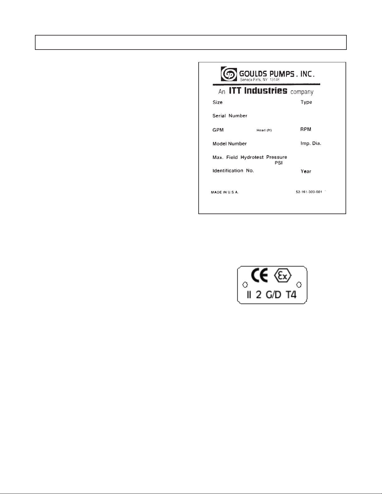
NAMEPLATE INFORMATION
Every pump has a Goulds Pumps nameplate that provides
information about the pump. The nameplate is located on
the pump casing.
Special tags which provide additional information
(mechanical seal data, etc.) and special tagging required by
customers are located on the pump casing or on the bearing
frame.
The standard nameplate (Fig. 1) provides information about
the pump size, type, serial number, rated head, capacity,
speed, impeller diameter, model number, and maximum
field hydrostatic test pressure.
The Identification No. is a number which the end user of
the pump requests to be put on the nameplate to identify the
pump in his operation.
The year indicates the year in which the pump was built.
Rating and hydrostatic test pressure are expressed in
English units. Note the format of pump size: Discharge x
Suction - Nominal Impeller Diameter in inches, for
example, 24x24-26.
The frame plate provides information concerning the
bearings and their lubrication. The inboard and outboard
bearing numbers refer to the bearing manufacturer’s
numbers.
When ordering spare parts you will need to identify pump
model, size, serial number, and the catalog number of
required parts. Pump information can be taken from the
Goulds Pumps nameplate. Catalog numbers can be found in
this manual.
Fig. 1
If applicable, your pump unit may have the following
ATEX tag affixed to the pump and/or baseplate. See the
Safety section for a description of the symbols and codes.
14 3498 IOM 12/04
Page 18
INSTALLATION
RECEIVING THE PUMP .........................15
LIFTING THE PUMP ...........................15
STORAGE REQUIREMENTS ......................17
LOCATION .................................20
FOUNDATION ...............................20
SETTING THE BASEPLATE (BEFORE PIPING) ...........21
ALIGNMENT PROCEDURE .......................22
DOWELING.................................23
SUCTION AND DISCHARGE PIPING .................24
STUFFING BOX LUBRICATION ....................26
RECEIVING THE PUMP
3
Check pump for shortages and damage immediately upon
arrival. Prompt reporting to the carrier’s agent with
notations made on the freight bill, will expedite satisfactory
adjustment by the carrier.
Horizontal pumps and drivers are normally shipped from
the factory mounted on a baseplate and painted with primer
and one finish coat. Couplings may either be completely
assembled or have the coupling hubs mounted on the shafts
and the connecting members removed. When the
connecting members are removed, they will be packaged in
a separate container and shipped with the pump or attached
to the baseplate.
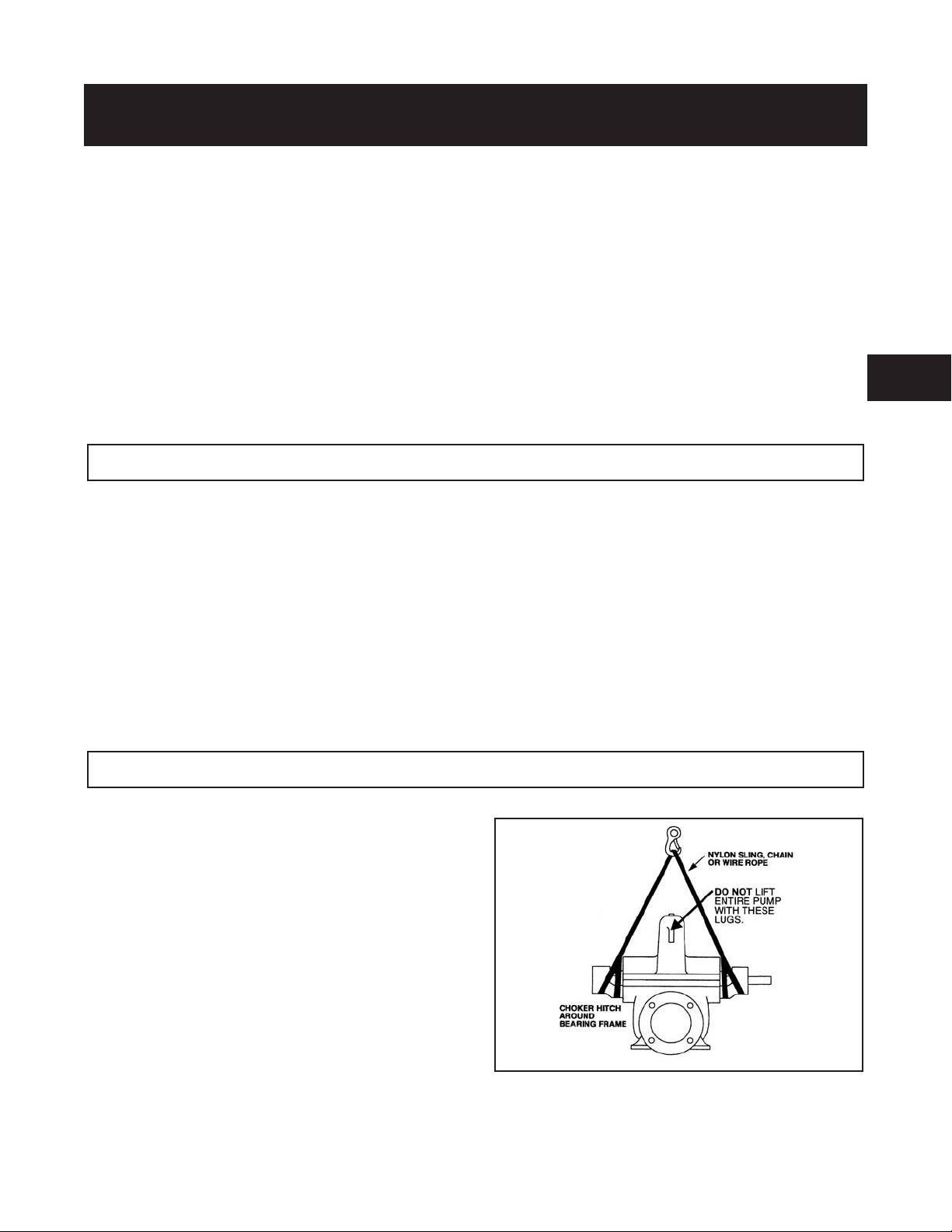
LIFTING THE PUMP
The following instructions are for the safe lifting of your pump.
The unit should be unloaded and handled by lifting equally
at four or more points on the baseplate. The lugs on the
upper half casing are designed for lifting the upper half
casing only.
HORIZONTAL
Bare Pump
1. Using a nylon sling, chain, or wire rope, hitch around
both bearing housings. (See Fig. 2)
Shafts are in alignment when unit is shipped; however, due
to shipping, the pumps may arrive misaligned and,
therefore, alignment must be established during
installation. Goulds Pumps has determined that proper and
correct alignment can only be made by accepted erection
practices. Refer to the following paragraphs on
“Foundation,” “Baseplate Setting,” “Grouting Procedure,”
“Alignment Procedure,” and “Doweling.”
Fig. 2
3498 IOM 12/04 15
Page 19

Pump, Base, And Driver
2. Care must be taken to size equipment for unbalanced
loads which may exist if the driver is not mounted on
the base at the time of lifting. Driver may or may not
be mounted at the factory.
3. Pump, base, and driver assemblies where the base
length exceeds 100 inches may not be safe to lift as a
complete assembly. Damage to the baseplate may
occur. If the driver has been mounted on the baseplate
at the factory, it is safe to lift the entire assembly. If
driver has not been mounted at the factory and the
overall baseplate length exceeds 100 inches, do not lift
entire assembly consisting of pump, base, and driver.
Instead, lift the pump and baseplate to its final location
without the driver. Then mount the driver.
Bases supplied with lifting holes
Large bases are supplied with lifting holes in the sides or
the ends of the base. (See Fig. 3)
Join the free ends of the slings together and place over the lifting
hook. Use extreme care when positioning sling under the driver
so it cannot slip off (See Fig. 4).
Fig. 4
VERTICAL
Half Pedestal
1. Place nylon sling chain or wire rope around both
flanges. Use a latch hook or standard shackle and end
loops.
Fig. 3
Using ANSI/OSHA Standard “S” hooks, place the “S”
hooks in the holes provided in the four corners of the base.
Be sure the points of the hooks do not touch the bottom of
the pump base. Attach nylon slings, chains, or wire rope to
the “S” hooks. Size the equipment for the load so the lift
angle will be less than 45° from the vertical.
Bases supplied without lifting holes
Place one sling around the outboard bearing housing.
! WARNING
s
Do not use lugs on top half of casing.
Place the remaining sling around the back end of the driver as
close to the mounting feet as possible. Make certain sling will not
damage housing cover or conduit boxes.
Be sure the lifting equipment is of sufficient length to
keep the lift angle less than 30° from the vertical (See
Fig. 5).
Fig. 5
16 3498 IOM 12/04
Page 20

Full Pedestal
2. Install eye bolts in the three holes provided at the top of the
support, being sure to tighten securely. Attach chain or wire
rope using latch hook or standard shackle and end loop.
Be sure to use shoulder eye bolts that are manufactured per
ANSI B18.15 and sized to fit the holes provided.
Be sure lifting equipment is of sufficient length to keep
the lift angle less than 30° from the vertical
(See Fig. 6).
3
Fig. 6
STORAGE REQUIREMENTS
Consider a Unit in Storage When:
1. It has been delivered to the job site and is awaiting
installation.
2. It has been installed, but operation is delayed pending
completion of planned construction.
3. There are long period (30 days) between operation cycles.
4. The plant or department is shut down.
TEMPORARY STORAGE OF
EQUIPMENT
This procedure applies to horizontal and vertical pumps
only for storage of one month or less. For longer periods,
refer to LONG TERM STORAGE OF EQUIPMENT.
Accessories such as motors, steam turbines, gears, etc.,
must be handled in accordance with the respective
manufacturer’s recommendations.
Oil Lube Frames
Storage requirements vary depending on length of storage
and the climatic environment.
If the equipment is not to be installed and operated soon
after arrival, store in a clean, dry, well ventilated place, free
from vibration and rapid or wide variations in temperatures.
On all rotating equipment, rotate the shaft several
revolutions every week to coat the bearings with lubricant,
retard oxidation or corrosion, and prevent possible
brinelling. Shaft extensions and other exposed machine
surfaces should be coated with an easily removable rust
preventative such as Tectyl No. 502C, Valvoline Oil
Company, Division of Ashland Petroleum Company.
NOTE: Oil lubricated pumps are shipped without
lubricant. Fill the frame completely with oil for
storage. Before putting equipment into operation,
drain the oil to proper level.
Grease Lube Frames
Storage requirements vary depending on length of storage
and the climatic environment.
If the equipment is not to be installed and operated soon after
arrival, store in a clean, dry, well ventilated place, free from
vibration and rapid or wide variations in temperatures.
On all rotating equipment, rotate the shaft several
revolutions every week to coat the bearings with lubricant,
retard oxidation or corrosion, and prevent possible
brinelling. Shaft extensions and other exposed machine
surfaces should be coated with an easily removable rust
preventative such as Tectyl No. 502C, Valvoline Oil
Company, Division of Ashland Petroleum Company.
3498 IOM 12/04 17
Page 21

LONG TERM STORAGE OF
EQUIPMENT
The following procedure applies to horizontal and vertical
pumps only for storage of one month or longer. Accessories such as motors, steam turbines, gears, etc. must be
handled in accordance with the respective manufacturer’s
recommendations.
Follow the same procedure for temporary storage in
addition to the following:
Bearing Frames
Oil Lubrication
Pumps with oil lubrication are shipped from the factory
without oil in the bearing frame. To prepare these frames
for storage:
1. Fill the bearing frame full with a lubricating oil
containing a rust preventative such as Mobilarma 500
Series oil. If this oil is to be used for initial operation
of the equipment, care should be taken to select an oil
suited to the intended operating temperature of the
pump. Check the supplier’s technical data and the
pump instruction book for this information.
2. Seal all vents and apply a waterproof tape around the
oil seals in the bearing frames.
$
Prior to using, drain all oil from the frame in case any
moisture has accumulated. Then refill to proper level
using the correct oil specified in the instruction book.
Grease Lubrication
Pumps are shipped from the factory with the bearings
pre-greased and should require no further lubrication.
It is recommended, however, that if the pumps are to be
stored in a humid environment or outside, add ½ ounce of
corrosion inhibiting concentrated oil such as Cortec’s
VCI-329 to the frame. Seal all vents and apply a waterproof
tape around the grease seals in the bearing frame.
Stuffing Box
Packing
Remove gland, lantern ring, packing base ring (if
applicable), and packing from stuffing box. If the packing
is in good condition, it may be saved; otherwise, it should
be discarded. Thoroughly clean and dry interior of the
stuffing box and shaft sleeve. Coat all interior parts of the
stuffing box, except for stainless materials with a soft film
rust preventative such as Valvoline Tectyl 502C or Cortec’s
VCI-369.
Seal end of stuffing box with waterproof tape.
NOTE: This tape will have to be removed and replaced
when the shaft is rotated.
CAUTION
Store gland, packing base ring, packing and lantern ring
until pump is ready to be put into service.
Mechanical Seal
Double Face Seal
Open uppermost flushing tap on stuffing box and fill cavity
with a lightweight (#10-#20) rust preventative oil such as
Mobilarma 500.
Single Face Seal
Remove flushing water plug to stuffing box and spray an
oil base volatile corrosion inhibitor such as Cortec’s
VCI-329 into the stuffing box cavity. Be sure to coat as
much of the interior of the cavity as possible.
The above procedures are not required if the seal box is of
a stainless material.
For both types of mechanical seals, regardless of material,
seal all vent and drain lines. Seal the point where the shaft
exits the box using waterproof tape.
NOTE: This tape will have to be removed and replaced
when the shaft is rotated.
NOTE: The majority of mechanical seals provided
have elastomer materials made of Buna-N, Neoprene,
or Viton™ which are not affected by hydrocarbon
based lubricants. If your pump has seals with
materials other than the above, it will be necessary to
check the compatibility of that material with the
manufacturer of the rust preventative used.
Final Preparation – Pumps of Non-Stainless Material
Coat all exposed machined surfaces (flanges, faces, shafts,
exposed locating fits, etc.) with a firm rust preventative
such as Valvoline Tectyl 890. Place a volatile corrosion
inhibitor device in the pump casing such as Cortec’s VCI
309, 101, or 110, depending on the pump size and
application.
! WARNING
s
For potable water, food, beverage, etc., pumps, the
corrosion inhibitor must be non-toxic. FAILURE TO
FOLLOW INSTRUCTIONS COULD RESULT IN
INJURY OR DEATH.
Regardless of material, cement rubber diaphragm flange
covers over the suction and discharge flanges. Protect these
rubber diaphragm covers with hardboard material. Make
sure all vents, drains, or plugs are tightly sealed.
The pump is now ready to be placed in storage.
NOTE: Storage locations that are near a source of
vibration such as railroad or truck traffic, heavy
machinery, or impacting machinery must be avoided to
prevent false brinelling of the pump bearings.
18 3498 IOM 12/04
Page 22

Indoor Storage
Little extra preparation is needed if indoor storage area is
dry and clean. Care should be taken to prevent extremes in
temperature (below 32°F and above 110°F). Also, keep the
pump out of direct sunlight and covered to protect it from
dust and dirt. Care should be taken to prevent moisture
build-up around the pump, either by allowing proper
ventilation or tightly sealing the pump in the cover with a
suitable amount of desiccant to ensure dryness.
If indoor storage area is humid or dirty, such as an
unfinished building, treat the pump as if it were to be stored
outdoors.
Installed, But Not In Service
Follow same procedures as for indoor storage, except
inspect the casing area once a month for moisture build-up,
replacing volatile corrosion inhibitor at that time.
Preparation for Operation
1. Remove all rust inhibitor from exposed machined
surfaces using the method described by the supplier.
2. Remove all corrosion protection devices or material
from pump casing.
3. If the pump has packing, repack pump using the
method described in the instruction book.
Outdoor Storage
Pump should be covered to protect it from weather and
direct sunlight. All coverings should be properly secured to
withstand high wind. Care must be exercised in covering
pumps to prevent moisture build-up under the cover. This
can be done either by allowing proper ventilation or tightly
sealing cover with suitable amount of desiccant to ensure
dryness.
Extreme heat and cold are to be avoided, as rubber parts
and seals could age prematurely (below 32°F and above
110°F).
Installed but Not in Service
Preparation for storage under these conditions is the same
as for indoor and outdoor, except the suction and discharge
piping will serve as flange covers.
The suction and discharge valves must be tightly closed
and all water removed from the pump and attached piping.
The Interior of the pump and piping must be thoroughly
dried.
Preparation procedures should be repeated every 12
months.
Maintenance
Indoor
The only maintenance required will be to rotate the pump
shaft 10-15 times twice a month. This operation is to recoat
the bearings with grease or oil and to prevent false
brinelling. Be sure the shaft comes to rest in different
positions.
Outdoor
Storage area should be inspected weekly, and after storms,
for damage to protective covers. Shafts should be rotated
10-15 turns three times a month.
Preparation procedure should be repeated every six months
for normal environments, and every two months for
corrosive environments (such as salt air).
4. If the pump has mechanical seals, drain protective oil
from seal cavity. Flush cavity with clean water or seal
lubricant for five minutes before start-up.
5. Remove flange covers, tape, and all unnecessary pipe
plugs.
6. Oil lubricated frames.
Drain rust preventative oil from frames and replace
with fresh oil. Note some rust preventative oils such as
the Mobilarma 500 can be used in the bearing frame
for start-up and initial running. Check the supplier’s
technical data and the pump instruction book to ensure
the oil used is of suitable viscosity and grade for the
intended application. If this is the case, drain the oil
from the bearing frame to the level indicated on the
sight gauge. When the oil used to protect the bearing
frame is used to run the pump on start-up, this oil
should be changed initially at half the recommended
time for oil changes (see instruction manual). Remove
tape from breather and seals.
7. Grease lubricated frames.
No special methods are required to prepare for
start-up. The corrosion inhibitor oil can be left in the
frame. Remove tape from breather and seals.
If the pumps are started with the factory supplied
grease, it is recommended that they be re-greased
initially at half the recommended grease interval.
Manufacturers of Recommended Products:
1. The Cortec Corporation
310 Chester Street
St. Paul, MN 55107
2. Valvoline Oil Company
Division of Ashland Petroleum Company
Contact Local Sales Officer or Ashland, Kentucky
3. Mobil Oil Corporation
Contact Local Sales Office
3
3498 IOM 12/04 19
Page 23

LOCATION
The pump should be installed as near the suction supply as
possible, with the shortest and most direct suction pipe
practical. The total dynamic suction lift (static lift plus
friction losses in suction line) should not exceed the limits
for which the pump was sold.
The pump must be primed before starting. Whenever
possible, the pump should be located below the fluid level
to facilitate priming and assure a steady flow of liquid. This
condition provides a positive suction head on the pump. It
is also possible to prime the pump by pressurizing the
suction vessel.
Pumps must be fully primed at all times during
!
operation.
When installing the pump, consider its location in relation
to the system to assure that sufficient Net Positive Suction
Head (NPSHA) is available at the pump inlet connection.
Available NPSH must always equal or exceed the required
NPSH (NPSHR) of the pump.
FOUNDATION
The pump should be installed with sufficient accessibility for
inspection and maintenance. A clear space with ample head
room should be allowed for the use of an overhead crane or
hoist sufficiently strong to lift the unit.
NOTE: Allow sufficient space to be able to dismantle
pump without disturbing the pump inlet and discharge
piping.
Select a dry place above the floor level wherever possible. Take
care to prevent pump from freezing during cold weather when
not in operation. Should the possibility of freezing exist during a
shut-down period, the pump should be completely drained, and
all passages and pockets where liquid might collect should be
blown out with compressed air.
Make sure there is a suitable power source available for the
pump driver. If motor driven, the electrical characteristics of the
power source should be identical to those shown on motor data
plate.
It is of prime importance to provide a foundation permanent
and rigid enough to absorb any vibration and maintain the
true alignment of a direct connected unit. (Hydraulic
Institute Standards recommends the foundation weigh at
least five [5] times the weight of the pump unit.) Usually a
concrete foundation on a solid base with embedded
foundation bolts of the proper size located with the aid of
general arrangement drawings is quite satisfactory.
A substantial foundation and footing should be built to suit
local conditions. It should form a rigid support to maintain
alignment.
Vertical Pumps – Foundation bolts should be sized and
accurately located. Each foundation bolt should be located
in a bushing two diameters larger than the bolt to allow free
movement of the bolt in conforming to the mounting holes
in the pedestal. When vertical pumps are used with
intermediate shafting, the motor mount baseplate should be
securely attached to the floor or support structure.
Horizontal Pumps – The foundation should be poured
without interruption to within 3/4 to 1-1/2 inches of the
finished height as shown in Fig. 7. The top surface of the
foundation should be well scored and grooved before the
concrete sets; this provides a bonding surface for the grout.
Foundation bolts should be set in concrete as shown in Fig. 7.
A 4-inch long tube around the bolts at the top of the concrete
will allow some flexibility in bolt alignment to match the holes
in the baseplate. Allow enough bolt length for grout, shims,
lower baseplate flange, nuts, and washers. The foundation
should be allowed to cure for several days before the baseplate
is shimmed and grouted.
Fig. 7
20 3498 IOM 12/04
Page 24

SETTING THE BASEPLATE (BEFORE PIPING)
NOTE: This procedure assumes that a concrete
foundation has been prepared with anchor or hold
down bolts extending up ready to receive unit. It must
be understood that pump and motor have been
mounted and rough aligned at the factory. If motor is
to be field mounted, consult factory for
recommendations. Goulds Pumps cannot assume
responsibility for final alignment.
1. Use blocks and shims under base for support at anchor
bolts and midway between bolts, to position base
approximately 1" above the concrete foundation with
studs extending through holes in the baseplate.
2. By adding or removing shims under the base, level and
plumb the pump shaft and flanges. The baseplate does
not have to be level.
3. Draw anchor nuts tight against base, and observe pump and
motor shafts or coupling hubs for alignment. (Temporarily
remove coupling guard for checking alignment.)
4. If alignment needs improvement, add shims or wedges at
appropriate positions under base so that retightening of
anchor nuts will shift shafts into closer alignment. Repeat
this procedure until a reasonable alignment is reached.
NOTE: Reasonable alignment is defined as that which
pump contractor and the accepting facility (final
operator) mutually agree upon. Final alignment
procedures are covered under “Alignment Procedure.”
1. Build strong form around the foundation to contain
grout.
2. Soak top of concrete foundation thoroughly, then
remove surface water.
3. Baseplate should be completely filled with grout and if
necessary, temporarily use air relief tubing or drill vent
holes to remove trapped air.
4. After the grout has thoroughly hardened, check the
foundation bolts and tighten if necessary.
5. Check the alignment after the foundation bolts are
tightened.
6. Approximately 14 days after the grout has been poured
or when the grout has thoroughly dried, apply an oil
base paint to the exposed edges of the grout to prevent
air and moisture from coming in contact with the
grout.
3
GROUTING PROCEDURE
Grout compensates for uneven foundation, distributes
weight of unit, and prevents shifting. Use an approved,
non-shrinking grout (such as Embeco 636 by Master
Builders, Cleveland, Ohio or equivalent), as follows, after
setting and leveling unit. (See Fig. 8).
Fig. 8
3498 IOM 12/04 21
Page 25

ALIGNMENT PROCEDURE
Alignment procedures must be followed to prevent
!
unintended contact of rotating parts. Follow
coupling manufacturer's installation and operation
procedures.
Proper rough alignment must be made during unit setting
and grouting. See previous section.
There are two forms of misalignment between the pump
shaft and the driver shaft as follows:
1. Angular misalignment — shafts have axis concentric
at intersection, but not parallel.
2. Parallel offset misalignment — shafts have axis
parallel, but offset.
The necessary tools for checking alignment are: (1) a straight
edge and a taper gauge or set of feeler gauges or, (2) a dial
indicator with mounting magnet and extension bars.
Check and correct for angular misalignment before correcting
parallel alignment. Final alignment should be made by moving
and shimming the motor on its base until the coupling hubs are
within the recommended tolerances measured in total run out.
All measurements should be taken with the pump and driver
bolts tightened. Final alignment check should be made after
the unit has attained its final operating temperature.
Method 1 - Using straight edge and taper gauges or feelers
(Fig. 9):
Proceed with this method only if satisfied that face and
outside diameters of the coupling halves are square and
concentric with the coupling bores. If this condition does
not exist or elastomeric couplings do not make this method
convenient, use Method 2.
Check for angular alignment by inserting the taper or feeler
gauges between the coupling faces at 90° intervals. The
unit is in angular alignment when these four (4)
measurements are the same, or within recommended
tolerances.
Check for parallel alignment by placing a straight edge
across both coupling rims on all four sides. The unit is in
parallel alignment when the straight edge rests evenly
across both coupling rims in all four (4) positions.
22 3498 IOM 12/04
Fig. 9
Page 26

Method 2 - Dial Indicators (Fig. 10):
A dial indicator can be used to attain more accurate
alignment.
Fasten the indicator stand or magnetic base to the pump
half of the coupling and adjust the assembly until the
indicator button is resting on the other half coupling
periphery.
Set the dial to zero and chalk mark the coupling half where
the button rests. Also place a separator between the
coupling halves so bearing slack does not affect the
readings. (Chalk and separators are not necessary on the
elastomeric couplings that have not been disconnected.)
Rotate both shafts by the same amount; i.e., all readings
must be made with the button on the chalk mark.
The dial readings will indicate whether the driver has to be
raised, lowered or moved to either side. Accurate alignment
of shaft centers can be obtained with this method even
where faces or outside diameters of the coupling are not
square or concentric with the bores. After each adjustment,
recheck both parallel and angular alignments.
Permissible coupling misalignment should be per the
coupling manufacturer's recommendation.
NOTE: Gross deviations in squareness or concentricity may cause rotation unbalance problems and if
so must be corrected.
3
DOWELING
Pump units may, if desired, (or required in specification) be
doweled on diagonally opposite feet. This should not be
done until the unit has been run for a sufficient length of
time and alignment is within the above alignment tolerance.
Fig. 10
3498 IOM 12/04 23
Page 27

SUCTION AND DISCHARGE PIPING
Flange loads from the piping system, including those
!
from thermal expansion of the piping, must not exceed
the limits of the pump. Casing deformation can result
in contact with rotating parts which can result in
excess heat generation, sparks and premature failure.
The introduction of pumpage into a piping system which is not
well designed or adjusted may cause strain on the pump, leading
to misalignment or even impeller rubbing. Since slight strain may
go unnoticed, final alignment should be done with the system full
and up to final temperature.
Pipe flanges should not impose any strain on the pump. This can
be checked by a dial indicator. Any strain must be corrected by
adjustments in the piping system.
When installing the pump piping, be sure to observe the following
precautions:
Piping should always be run to the pump.
Do not move the pump to pipe. This could make final alignment
impossible.
Where flanged joints are used, assure that inside diameters match
properly.
Remove burrs and sharp edges when making up joints.
Fig. 11
Do not “spring” piping when making any connections.
Provide for pipe expansion when hot fluids are to be pumped.
Both the suction and discharge piping should be independently
anchored near the pump and properly aligned so that no strain is
transmitted to the pump when the flange bolts are tightened. Use
pipe hangers or other supports at necessary intervals to provide
support. When expansion joints are used in the piping system they
must be installed beyond the piping supports closest to the pump.
Tie bolts and spacer sleeves should be used with expansion joints
to prevent pipe strain. Do not install expansion joints next to the
pump or in any way that would cause a strain on the pump
resulting from system pressure changes. When using rubber
expansion joints, follow the recommendations of the Technical
Handbook on Rubber Expansion Joints and Flexible Pipe
Connectors. It is usually advisable to increase the size of both
suction and discharge pipes at the pump connections to decrease
the loss of head from friction.
Install piping as straight as possible, avoiding unnecessary bends.
Where necessary, use 45° or long radius 90° fittings to decrease
friction losses.
Make sure that all piping joints are air-tight.
SUCTION PIPING
When installing the suction piping, observe the following
precautions. (See Fig. 12)
The sizing and installation of the suction piping is extremely
important. It must be selected and installed so that pressure
losses are minimized and sufficient liquid will flow into the
pump when started and operated.
Many NPSH (Net Positive Suction Head) problems can be
directly attributed to improper suction piping systems.
Suction piping should be short in length, as direct as
possible, and never smaller in diameter than the pump
suction opening. A minimum of five (5) pipe diameters
between any elbow or tee and the pump should be allowed.
If a long suction pipe is required, it should be one or two
sizes larger than the suction opening, depending on its
length.
24 3498 IOM 12/04
Page 28

$
An elbow should not be used directly before the suction of a
double suction pump if its plane is parallel to the pump
shaft. This can cause an excessive axial load or NPSH
problems in the pump due to an uneven flow distribution
(See Fig. 11). If there is no other choice, the elbow should
have straightening vanes to help evenly distribute the flow.
Eccentric reducers should be limited to one pipe size
reduction each to avoid excessive turbulence and noise.
They should be of the conical type. Contour reducers are
not recommended.
When operating on a suction lift, the suction pipe should
slope upward to the pump nozzle. A horizontal suction line
must have a gradual rise to the pump. Any high point in the
pipe can become filled with air and prevent proper
operation of the pump. When reducing the piping to the
suction opening diameter, use an eccentric reducer with the
eccentric side down to avoid air pockets.
NOTE: When operating on suction lift never use a
concentric reducer in a horizontal suction line, as it
tends to form an air pocket in the top of the reducer
and the pipe.
Fig. 12 shows some correct and incorrect suction piping
arrangements.
CAUTION
3
Fig. 12
When installing valves in the suction piping, observe the
following precautions:
1. If the pump is operating under static suction lift
conditions, a foot valve may be installed in the suction
line to avoid the necessity of priming each time the
pump is started. This valve should be of the flapper
type, rather than the multiple spring type, sized to
avoid excessive friction in the suction line. (Under all
other conditions, a check valve, if used, should be
installed in the discharge line. See Discharge Piping.)
2. When foot valves are used, or where there are other
possibilities of “water hammer,” close the discharge
valve slowly before shutting down the pump.
3. Where two or more pumps are connected to the same
suction line, install gate valves so that any pump can
be isolated from the line. Gate valves should be
installed on the suction side of all pumps with a
positive pressure for maintenance purposes. Install
gate valves with stems horizontal to avoid air pockets.
Globe valves should not be used, particularly where
NPSH is critical.
$
The pump must never be throttled by the use of a valve
on the suction side of the pump. Suction valves should
be used only to isolate the pump for maintenance
purposes, and should always be installed in positions
to avoid air pockets.
CAUTION
3498 IOM 12/04 25
Page 29

DISCHARGE PIPING
If the discharge piping is short, the pipe diameter can be the
same as the discharge opening. If the piping is long, the
pipe diameter should be one or two sizes larger than the
discharge opening. On long horizontal runs, it is desirable
to maintain as even a grade as possible. Avoid high spots,
such as loops, which will collect air and throttle the system
or lead to erratic pumping.
A check valve and an isolating gate valve should be
installed in the discharge line. The check valve, placed
between pump and gate valve, protects the pump from
excessive back pressure, and prevents liquid from running
back through the pump in case of power failure. The gate
valve is used in priming and starting, and when shutting the
pump down.
STUFFING BOX LUBRICATION
PRESSURE GAUGES
Properly sized pressure gauges should be installed in both
the suction and discharge nozzles in the gauge taps
provided. The gauges will enable the operator to easily
observe the operation of the pump, and also determine if
the pump is operating in conformance with the
performance curve. If cavitation, vapor binding, or other
unstable operation should occur, widely fluctuating
discharge pressure will be noted.
Contaminants in the pumped liquid must not enter the
stuffing box. These contaminants may cause severe
abrasion or corrosion of the shaft, or shaft sleeve, and rapid
packing or mechanical seal deterioration; they can even
plug the stuffing box flushing and lubrication system. The
stuffing box must be supplied at all times with a source of
clean, clear liquid to flush and lubricate the packing or seal.
The most important consideration is to establish the
optimum flushing pressure that will keep contaminants
from the stuffing box cavity. If this pressure is too low,
fluid being pumped may enter the stuffing box. If the
pressure is too high, excessive packing or seal wear may
result; and extreme heat may develop in the shaft causing
higher bearing temperatures. The most desirable condition,
therefore, is to use a seal water pressure 15-20 psig above
the maximum stuffing box pressure.
If the pump system pressure conditions vary, packing
adjustment becomes difficult. Consideration should be
given to using a mechanical seal (See Mechanical Seals).
PACKING
Packed stuffing boxes are not allowed in an ATEX
!
classified environment.
Pumps are normally shipped with the packing set loose. If
the pump is installed within 60 days after shipment, the
packing will be in good condition with a sufficient supply
of lubrication. If the pump is stored for a longer period, it
may be necessary to repack the stuffing box. In all cases,
however, inspect the packing before the pump is started.
NOTE: Packing adjustment is covered in the
Preventive Maintenance section of this manual
On some applications, it is possible to use internal liquid
lubrication (pumped liquid) to lubricate packing. Only
when all of the conditions prevail, can this be done:
1. Liquid is clean, free from sediment and chemical
precipitation and is compatible with seal materials.
2. Temperature is above 32° F and below 160° F.
3. Suction pressure is below 75 psig.
4. Lubrication (pumped liquid) has lubricating qualities.
5. Liquid is non-toxic and non-volatile.
When the liquid being pumped contains solids or is
otherwise not compatible with packing materials, an
outside supply of seal liquid should be furnished. In
general, external-injection liquid (from an outside source)
is required when any of the above conditions cannot be
met.
The standard stuffing box consists of six (6) rings of
packing and a split type gland. A shaft sleeve which
extends through the box and under the gland is provided to
protect the shaft.
A tapped hole is supplied in the stuffing box directly over
the seal cage to introduce a clean, clear sealing medium.
The stuffing box must, at all times, be supplied with sealing
liquid at a high enough pressure to keep the box free from
foreign matter, which would quickly destroy the packing
and score the shaft sleeve.
Only a sufficient volume of sealing liquid to create a
definite direction of flow from the stuffing box inward to
the pump casing is required, but the pressure is important.
Apply seal water at a rate of approximately 0.5-1.0 GPM at
a pressure approximately 15 to 20 psig above the suction
pressure. (Approximately one [1] drop per second).
26 3498 IOM 12/04
Page 30

One recommended method to minimize error in regulating
flushing water is a “Controlled Pressure System” (Fig. 13).
Most important is the pressure reducing valve adjusted to a
value slightly exceeding the maximum stuffing box
operating pressure (assuming it is reasonably constant). A
flow indicating device will serve to indicate a failing of the
bottom packing rings allowing leakage into the pump.
Just as with packing, the mechanical seal chamber must be
supplied, at all times, with a source of clean, clear liquid to
flush and lubricate the seal. The most important
consideration is to establish the optimum flushing pressure
that will keep contaminants from the seal cavity. If this
pressure is too low, fluid being pumped may enter the
stuffing box. If the pressure is too high, excessive seal
wear may result.
When contaminants are present in the pumpage, an external
source of clean seal water must be supplied. Supply
approximately 0.5 - 1.0 GPM at a pressure approximately
15 to 20 psig above the suction pressure.
Fig. 13 shows the recommended "Controlled Pressure
System" for a mechanical seal. Seal water enters the seal
chamber, lubricates the seal face, and exits into the pump
itself. Positive flow in the seal water line indicates
adequate seal water pressure.
3
Fig. 13
External sealing liquid should be adjusted to the point
where the packing runs only slightly warm, with a very
slow drip from the stuffing box. Excess pressure from an
external source can be very destructive to packing. More
pressure is required, however, for abrasive slurries than for
clear liquids. Examination of the leakage will indicate
whether to increase or decrease external pressure. If slurry
is present in the leakage, increase the pressure until only
clear liquid drips from the box. If the drippage is corrosive
or harmful to personnel, it should be collected and piped
away.
A common error is to open the external piping valve wide
and then control the drippage by tightening the packing
gland. Actually, a combination of both adjustments is
essential to arrive at the optimum condition. The life of
packing and sleeve depends on this careful control more
than any other factor.
MECHANICAL SEALS
The mechanical seal used in an ATEX classified
!
environment must be properly certified.
Mechanical seals are preferred over packing on some
applications because of better sealing qualities and longer
serviceability. Leakage is eliminated when a seal is
properly installed, and normal life is much greater than that
of packing on similar applications. A mechanical shaft seal
is supplied in place of a packed stuffing box when
specifically requested. The change from packing to an
alternate arrangement may be made in the field by
competent service personnel. Conversion parts may be
ordered from your Goulds Pumps Sales Representative.
CARTRIDGE SEALS
Follow the appropriate lubrication directions for
mechanical seals given in this section. Most cartridge seals
provide flushing connections on their glands. use the
cartridge seal gland flushing taps (if provided) for your seal
water connections instead of the stuffing box tap. The
quench taps on the glands (if present) are normally only
used in chemical applications. Consult seal manufacturer's
literature for more detailed information.
The mechanical seal must have an appropriate seal
!
flush system. Failure to do so will result in excess
heat generation and seal failure.
CYCLONE SEPARATOR
If the fluid being pumped contains sediment and there is no
external, clean water source available to flush the packing
or mechanical seals, a cyclone separator can be used to
remove most of the sediment from the liquid being pumped
so it can be used to flush the seals. The separator is placed
in the seal water piping line and removes the sediment to
an external drain (normally back to the pump suction line).
3498 IOM 12/04 27
Page 31

28 3498 IOM 12/04
Page 32

OPERATION
PRE-START CHECKS...........................29
PRIMING ..................................30
Flushing .................................30
Filling...................................30
STARTING .................................30
OPERATIONAL CHECKLIST ......................31
SHUTDOWN ................................31
FREEZING PROTECTION ........................31
FIELD TESTS................................32
VIBRATION ................................33
ELECTRICAL REQUIREMENTS ....................33
PRE-START CHECKS
When installing in a potentially explosive environment,
!
ensure that the motor is properly certified.
Before the initial start of the pump, make the following inspections:
1. Check alignment between pump and driver. See the
section on alignment for alignment requirements.
All equipment being installed must be properly
!
grounded to prevent unexpected static electric
discharge.
2. Check all connections to motor and starting device with
wiring diagram. Check voltage, phase, and frequency on
motor nameplate with line circuit.
3. Check suction and discharge piping and pressure gauges
for proper operation.
4. Turn rotating element by hand to assure that it rotates
freely.
Rotate shaft by hand to ensure it rotates smoothly
!
and there is no rubbing which could lead to excess
heat generation and sparks.
5. Check stuffing box adjustment, lubrication, and piping.
6. Check driver lubrication.
10. Check rotation. Be sure that the driver operates in the
direction indicated by the arrow on the pump casing as
serious damage can result if the pump is operated with
incorrect rotation. Check rotation each time the motor
leads have been disconnected.
Cooling systems such as those for bearing lubrication,
!
mechanical seal systems, etc, where provided, must be
operating properly to prevent excess heat generation,
sparks, and premature failure.
Check for magnetism on the pump shaft and degauss
!
the shaft if there is any detectable magnetism.
Magnetism will attract ferritic objects to the impeller,
seal and bearings which can result in excess heat
generation, sparks, and premature failure.
Leakage of process liquid may result in creating an
!
explosive atmosphere. Ensure the materials of the
pump casing, impeller, shaft, sleeves, gaskets, and
seals are compatible with the process liquid.
Leakage of process liquid may result in creating an
!
explosive atmosphere. Follow all pump and seal
assembly procedures.
4
Bearings must be lubricated properly in order to
!
prevent excess heat generation, sparks, and
premature failure.
7. Assure that pump bearings are properly lubricated.
8. Assure that coupling is properly lubricated, if required.
9. Assure that pump is full of liquid and all valves are
properly set and operational, with the discharge valve and
the suction valve open. Purge all air from top of casing.
3498 IOM 12/04 29
A build-up of gases within the pump, sealing system
!
and/or process piping system may result in an explosive
environment within the pump or process piping system.
Ensure process piping system, pump, and sealing system
are properly vented prior to operation.
Sealing systems that are not self purging or self
!
venting, such as plan 23, require manual venting
prior to operations. Failure to do so will result in
excess heat generation and seal failure.
Page 33

PRIMING
If the pump is installed with a positive head on the suction,
it can be primed by opening the suction valve, and
loosening the vent plug on the top of the casing (Do not
remove), allowing air to be purged from the casing.
If the pump is installed with a suction lift, priming must be
done by other methods such as foot valves, ejectors, or by
manually filling the casing and suction line.
$
Under either condition, the pump must be completely
filled with liquid before starting. The pump must not be
run dry in the hope it will prime itself. Serious damage
to the pump may result if it is started dry.
Ensure that pump and systems are free of foreign
!
objects before operating and that objects cannot
enter the pump during operation. Foreign objects in
the pumpage or piping system can cause blockage of
flow which can result in excess heat generation,
sparks, and premature failure.
!CAUTION
FLUSHING
New and old systems should be flushed to eliminate all
foreign matter. Heavy scale, welding splatter and wire or
other large foreign matter can clog the pump impeller. This
will reduce the capacity of the pump causing cavitation,
excessive vibration, and/or damage to close clearance parts
(wear rings, seals, sleeves, etc.)
FILLING
Vents should be located at the highest point so
entrained gases and air can escape. However, if the
gases are flammable, toxic, or corrosive they should be
vented to an appropriate place to prevent harm to
personnel or other parts of the system. Pipe hangers
and anchors should be checked to make sure they are
properly set to take the additional weight of the
pumpage.
All drains should be closed when filling the system. Filling
should be done slowly so that excessive velocities do not
cause rotation of the pumping elements which may cause
damage to the pump or its driver. The adequacy of the anchors
and hangers may be checked by mounting a dial indicator off
of any rigid structure not tied to the piping and setting the
indicator button on the pump flange in the axial direction of
the nozzle. If the indicator moves, as the filling proceeds, the
anchors and supports are not adequate or set properly and
should be corrected.
STARTING
1. Close drain valves.
2. Open fully all valves in the suction and discharge
lines.
3. Turn on seal water to the stuffing box. (If pumped
fluid is dirty or if leaking of air is to be prevented,
these lines should be always left open.)
4. Prime the pump.
$
If the pump does not prime properly, or loses prime
during start-up, it should be shutdown and the
condition corrected before the procedure is repeated.
5. Start the pump driver (turbines and engines may
require warming up; consult the manufacturer’s
instructions).
6. When the pump is operating at full speed, check to see
that the check valve has opened up. Check valve must
CAUTION
open 5 seconds or less after start-up to prevent damage
to pump by operating at zero flow.
7. Adjust the liquid seal valves to produce the
recommended pressure for either the mechanical seal
or packed stuffing box.
30 3498 IOM 12/04
Page 34

OPERATIONAL CHECKLIST
1. Driver/Pump Rotation
Check rotation each time the motor leads have been
disconnected. Be sure that the driver operates in the
direction indicated by the arrow on the pump casing.
Rough operation and extreme vibration can result if the
pump is operated in the wrong direction.
2. Stuffing Box Adjustment
Make stuffing box packing gland and lubrication
adjustments.
3. Flow
An accurate measurement of flow rate (volume/time) is
difficult in the field. Venturi meters, flow nozzles,
orifice plates, or timing the draw down in the wet well
are all possible methods. Record any reading for future
reference.
4. Pressure
Check and record both suction and discharge pressure
gauge readings for future reference. Also, record
voltage, amperage per phase, kilowatts if an indicating
watt meter is available, and pump speed.
5. Temperature
Do not insulate bearing housings as this can result
!
in excess heat generation, sparks, and premature
failure.
Check and record bearing temperatures using a
thermometer. Temperature should not exceed 180° F.
NOTE: Just because bearing housings are too hot to
touch does not mean that they are running too hot
for proper operation.
6. Vibration and Sound
The acceptable vibration level of a centrifugal pump
depends on the rigidity of the pump and the supporting
structure. Recommended values for vibration can vary
depending on the operating characteristics and the
structure. Refer to the Centrifugal Pump section of the
Hydraulic Institute Standards for a complete
description and charts on various pumps.
Field sound levels are difficult to measure because of
background noise from piping, valves, drivers, gears,
etc. Follow recommendations in the Hydraulic
Institute Standards.
4
SHUTDOWN
The following steps will take care of most normal
shutdowns of the pump, i.e. maintenance. Make any further
adjustments of process piping, valves, etc., as required. If
the pump is to be removed from service for an extended
period of time, refer to the sections on storage and freeze
protection.
1. Shut down the driver. (Consult manufacturer’s
instructions for special operations.)
2. Close suction and discharge valves.
FREEZE PROTECTION
Pumps that are shut down during freezing conditions
should be protected by one of the following methods.
1. Drain the pump; remove all liquid from the casing.
2. Keep fluid moving in the pump and insulate or heat the
pump to prevent freezing.
3. Close seal liquid valves. (If pumped liquid is dirty, or
if leakage is to be prevented, these lines should always
be left open, except when the pump is completely
drained.)
4. Open drain valves as required.
$
If heat is used to keep the pump from freezing, do not
let the temperature rise above 150° F.
CAUTION
3498 IOM 12/04 31
Page 35

FIELD TESTS
PERFORMANCE CURVE
A typical performance curve for a specific pump can be
obtained from Goulds Pumps. This can be used in
conjunction with a field test, if one is required. All Goulds
Pumps pump tests, and curves, are based on the “Hydraulic
Institute Standards.” Any field test must be conducted
according to these Standards. Unless otherwise specifically
agreed, all capacity, head, and efficiencies are based on
shop tests when handling clear, cold, fresh water at a
temperature not over 85° F and under suction conditions as
specified in the contract.
DEFINITIONS
To aid in calculating pump performance, the following test
information and definitions are included for reference. See
Appendix III for other useful formulas, and Appendix IV for
a Field Test Report Sheet.
NOTE: Complete procedure for testing pumps is
given in the “Hydraulic Institute Standards”
Centrifugal Pump Section.
Gauge Datum
The datum for all gauge readings is taken as the centerline
of the pump shaft for all horizontal shaft pumps and as the
eye of the impeller for vertical pumps.
Head Measurement
The unit for measuring head should be feet; therefore, all
pressure readings of the pumped liquid should be converted
to feet. The relationship between a pressure expressed in
pounds per square inch (psi) and that expressed in feet of
head is:
Head in feet = psig x 2.31
sg
Where sg = specific gravity of the liquid pumped
Where sg = 1.0 for water at 70°
Total Head
Total head is the algebraic difference between the total
suction and the total discharge heads.
1. Where suction lift exists, total head is the sum of the
total discharge head and the suction lift.
2. Where positive suction head exists, the total head is
the total discharge head minus the total suction head.
Suction Lift
Suction lift exists where the total suction head is below
atmospheric pressure. Total suction lift is the reading of a
liquid manometer at the suction nozzle of the pump,
converted to feet of liquid, and referred to the datum minus
the velocity head at the point of gauge attachment.
Positive Suction Head
Suction head exists when the total suction head is above
atmospheric pressure. Total suction head is the reading of a
gauge at the suction of the pump, converted to feet of
liquid, and referred to datum plus the velocity head at the
point of gauge attachment.
Velocity Head
Velocity head is figured from the average velocity obtained
by dividing the discharge flow (in cubic feet per second) by
the actual area of the pipe cross-section (in square feet),
and is determined at the point of gauge connection. It is
expressed by the formula:
2
=V
h
v
2g
Where g = the acceleration due to gravity, and is
32.17 feet per second squared at sea level
and 45° latitude.
V = velocity in the pipe in feet per second.
Volume Measurement
The method of volume measurement should be made by
some accurate and accepted method and converted to
gallons per minute. For easy reference, refer to the
following:
1. The standard U.S. gallon contains 231 cubic inches.
2. One cubic foot equals 7.4805 gallons.
3. The specific weight of water at a temperature of 60°
shall be taken as 62.34 pounds per cubic foot.
Horsepower
1. The formula for horsepower required at the pump shaft
is:
Total head x GPM
Bhp =
3960 x Eff.
2. The true motor brake horsepower, once the efficiency
is determined from dynamometer tests, can also be
calculated from the following formula:
kw input x Eff.
Bhp =
Where Bhp = Brake horsepower delivered
Kw input = Real input power (kw)
Eff. = Motor efficiency
x specific gravity
0.746
32 3498 IOM 12/04
Page 36

Pump Efficiency
Pump efficiency can be calculated by the formula:
Pump Efficiency =
Total head x GPM
3960 x Bph
x specific gravity
VIBRATION
The acceptable vibration level of a centrifugal pump
depends on the rigidity of the pump and the supporting
structure. Recommended values for vibration can vary
depending on the operating characteristics and the
structure. Refer to the standards of the “Hydraulic
Institute” for the complete description and charts on various
structures.
ELECTRICAL REQUIREMENTS
Motor (Also See Separate Motor Instructions)
If the motor is sized to operate near full load at the rated
head and capacity of the pump, a watt-meter should be
installed to record input power to the motor. If motor
efficiency is known, the shaft horsepower may be
calculated and checked against the motor rating.
A motor operating outside its service factor will overheat and
could possibly burn out. Motors are usually rated with
normal temperature requirements stamped on the data plate.
4
Motor Controls – General
Motor controls should conform to all the electrical data
stamped on the motor data plate. Complete instructions for
installation, operation, and maintenance are included with
the controlling device.
External Wiring
Wiring to the motor should be installed in conformance
with the National Electrical Code and any local codes.
NOTE: A motor which feels hot to the touch of the
hand is not necessarily running hot. Check with an
accurate temperature measuring device to be sure. A
motor operating outside its service factor will overheat
and could possibly burn out. Motors are usually rated
with normal temperature requirements stamped on the
data plate.
Conduit Box
Conduit boxes are mounted on the motors at lead access
openings. Conduit boxes are normally provided for main
power leads and other special accessories, such as space
heaters, temperature alarms and control features.
The conduit box openings are sized as shown on the motor
dimension drawing, and threaded for using standard rigid
or flexible conduit. They may be assembled with conduit
openings at any of four (4) 90° positions.
3498 IOM 12/04 33
Page 37

34 3498 IOM 12/04
Page 38

PREVENTIVE MAINTENANCE
GENERAL MAINTENANCE .......................35
MAINTENANCE TIMETABLE......................35
MAINTENANCE OF FLOOD DAMAGED PUMPS ..........36
LUBRICATION...............................36
SEALING INFORMATION ........................38
TROUBLESHOOTING ..........................40
GENERAL MAINTENANCE
One of the best rules to follow in the proper maintenance of
The Preventive Maintenance section must be
!
adhered to in order to keep the applicable ATEX
classification of the equipment. Failure to follow
these procedures will void the ATEX classification
for the equipment.
Operating conditions vary so widely that to recommend one
schedule of preventive maintenance for all centrifugal
pumps is not possible. Yet some sort of regular inspection
must be planned and followed. We suggest a permanent
record be kept of the periodic inspections and maintenance
performed on your pump. This recognition of maintenance
procedure will keep your pump in good working condition,
and prevent costly breakdowns.
your centrifugal pump is to keep a record of actual
operating hours. Then, after a predetermined period of
operation has elapsed, the pump should be given a
thorough inspection. The length of this operating period
will vary with different applications, and can only be
determined from experience. New equipment, however,
should be examined after a relatively short period of
operation. The next inspection period can be lengthened
somewhat. This system can be followed until a maximum
period of operation is reached which should be considered
the operating schedule between inspections.
5
MAINTENANCE TIMETABLE
INSPECTION INTERVALS
Inspection intervals should be shortened
!
appropriately if the pumpage is abrasive and/or
corrosive, or if the environment is classified as
potentially explosive.
EVERYMONTH
Check bearing temperature with a thermometer, not by hand.
If bearings are running hot (over 180° F), it may be the result
of too much or too little lubricant. If changing the lubricant
and/or adjusting to proper level does not correct the condition,
disassemble and inspect the bearings. Lip seals bearing on the
shaft may also cause the housing to run hot. Lubricate lip seals
to correct this condition.
EVERY3 MONTHS
Check the oil on oil lubricated units. Check grease lubricated
bearings for saponification. This condition is usually caused
by the infiltration of water or other fluid past the bearing shaft
seals and can be noticed immediately upon inspection, since it
gives the grease a whitish color. Wash out the bearings with a
clean industrial solvent and replace the grease with the proper
type as recommended.
EVERY6 MONTHS
Check the packing and replace if necessary. Use the grade
recommended. Be sure the seal cages are centered in the
stuffing box at the entrance of the stuffing box piping
connection.
Take vibration readings on the bearing housings. Compare the
readings with the last set of readings to check for possible
pump component failure (e.g. bearings).
Check shaft or shaft sleeve for scoring. Scoring accelerates
packing wear.
3498 IOM 12/04 35
Page 39

Check alignment of pump and driver. Shim up units if
necessary. If misalignment reoccurs frequently, inspect the
entire piping system. Unbolt piping at suction and discharge
flanges to see if it springs away, thereby indicating strain on
the casing. Inspect all piping supports for soundness and
effective support of load. Correct as necessary.
EVERY YEAR
Remove the upper half of the casing. Inspect the pump
thoroughly for wear, and order replacement parts if
necessary.
Check wear ring clearances. Replace when clearances
become three (3) times their normal clearance or when a
significant decrease in discharge pressure for the same flow
rate is observed.
Remove any deposit or scaling. Clean out stuffing box
piping.
Measure total dynamic suction and discharge head as a test of
pump performance and pipe condition. Record the figures and
compare them with the figures of the last test. This is important,
especially where the fluid being pumped tends to form a deposit
on internal surfaces. Inspect foot valves and check valves,
especially the check valve which safeguards against water
hammer when the pump stops. A faulty foot or check valve will
reflect also in poor performance of the pump while in operation.
NOTE: The above timetable is based on the assumption that
after startup, the unit has been constantly monitored and
such a schedule was found to be consistent with operation, as
shown by stable readings. Extreme or unusual applications
or conditions should be taken into consideration when
establishing the maintenance intervals.
MAINTENANCE OF FLOOD DAMAGED PUMPS
The servicing of centrifugal pumps after a flooded
condition is a comparatively simple matter under normal
conditions.
Bearings are a primary concern on pumping units. First,
dismantle the bearings; clean and inspect them for any
rusted or badly worn surfaces. If bearings are free from rust
and wear, reassemble and relubricate them with one of the
recommended pump lubricants. Depending on the length of
time the pump has remained in the flooded area, it is
unlikely that bearing replacement is necessary; however, in
the event that rust or worn surfaces appear, it may be
necessary to replace the bearings.
LUBRICATION
GREASE
Grease lubricated ball bearings are packed with grease at
the factory and ordinarily will require no attention before
starting provided the pump has been stored in a clean, dry
place prior to its first operation. The bearings should be
watched the first hour or so after the pump has been started
to see that they are operating properly.
The importance of proper lubrication cannot be over
emphasized. It is difficult to say how often a bearing should
be greased, since that depends on the conditions of
operation. It is well to add one ounce of grease at regular
intervals, but it is equally important to avoid adding too
much grease. For average operating conditions, it is
recommended that 1 oz. of grease be added at intervals of
Next, inspect the stuffing box, and clean out any foreign
matter that might clog the box. Packing that appears to be
worn, or no longer regulates leakage properly should be
replaced. Mechanical seals should be cleaned and
thoroughly flushed.
Couplings should be dismantled and thoroughly cleaned.
Lubricate the coupling with one of the coupling
manufacturer’s recommended lubricants where required.
Any pump that is properly sealed at all joints and
connected to both the suction and discharge should exclude
outside liquid. Therefore, it should not be necessary to go
beyond the bearings, stuffing box, and coupling when
servicing the pump.
three to six months, and only clean grease be used. It is
always best if unit can be stopped while grease is added to
avoid overloading.
NOTE: Excess grease is the most common cause of
overheating.
The bearing frame should be kept clean, since any
contamination of foreign matter which gets into the
housing will destroy bearings in a short time. When
cleaning bearings, use a bearing cleaning solvent, or an
industrial cleaning solvent. Do not use gasoline. Use lint
free cloths. Do not use waste rags.
A regular ball bearing grease should be used, but a standard
commercial vaseline can be substituted if necessary.
36 3498 IOM 12/04
Page 40

Do not use graphite. A No.1 or 2 grease is generally
satisfactory for operation at ordinary temperatures, the
lighter grease for operation at high speed or low room
temperature.
Mineral greases with a soda soap base are recommended.
Grease made from animal or vegetable oils are not
recommended due to the danger of deterioration and
forming of acid. Most of the leading oil companies have
special bearing greases which are satisfactory. For specific
recommendations, consult the factory.
Experience shows that oils meeting the following
specifications will provide satisfactory lubrication. These
oils can be furnished by all major oil companies. It is the
responsibility of the oil vendor to supply a suitable
lubricant.
(1) Saybolt viscosity at 100° F ....215-SSU-240 SSU
(2) Saybolt viscosity at 210° F ...........49SSU
(3)Viscosityindex,minimum...............95
The maximum desirable operating temperature for ball
bearings is 180°F. Should the temperature of the bearing
frame rise above 180°F, the pump should be shut down to
determine the cause.
Grease lubricated bearings should not be used where
temperature of the pumped liquid exceeds 350°F.
NOTE: A bearing frame which feels hot to the touch
of the hand is not necessarily running hot. Check with
an accurate temperature measuring device to be sure.
OIL
Bearings must be lubricated properly in order to
!
prevent excess heat generation, sparks and
premature failure.
The oil-lubricated pumps may have an oiling ring, in which
the oil is picked up from the reservoir by a rotating oil ring
and deposited on the shaft and bearings inside the bearing
housing; or they may have an oil slinger, which creates a
shower of fine droplets over the entire interior of the
bearing cavity.
After the pump has been installed, flush the bearing
housing to remove dirt, grit and other impurities that may
have entered the bearing housing during shipment or
erection. Then refill the bearing housing with proper
lubricant. The oil level to be maintained is shown by a line
in the sight glass or oil level indicator.
(4)APIgravity.................... .28-33
(5)Pourpoint,maximum...............+20°F
(6)Flashpoint,minimum...............400° F
(7) Additives ...........Rust&OxidationInhibitors
(8) ISO Viscosity ....................46
NOTE: Oils from different supplies should not be
mixed.
The oil should be well refined, good grade, straight cut,
filtered mineral oil. It must be free from water, sediment,
resin, soaps, acid, and fillers of any kind. It should also be
non-foaming with a viscosity of about 150-200 SSU at
100°F. (Approximately SAE-20.)
In installations with moderate temperature changes,
humidity, and dirt, the oil should be changed after
approximately 160 hours of operation. The oil should be
inspected this time to determine the operating period before
the next oil change. Oil change periods may be increased
up to 2000-4000 hours based on an 8000-hour year. Check
the oil frequently for moisture, dirt or signs of
“breakdown.”
$
Do not over oil; this causes the bearings to run hot.
The maximum desirable operating temperature for
ball bearings is 180°F. Should the temperature of the
bearing frame exceed 180°F (measure by thermometer), shut down pump to determine the cause.
CAUTION
5
3498 IOM 12/04 37
Page 41

SEALING INFORMATION
WATER LUBRICATION
Only a sufficient volume of sealing liquid to create a
definite direction of flow from the stuffing box inward to
the pump casing is required, but the pressure is important.
Apply seal water at a rate of 0.5 - 1.0 GPM, at 15 -20 PSI
above stuffing box operating pressure.
We recommend that piping supplying sealing liquid to
stuffing box be sized to supply a sufficient volume of water
at the required pressure, based on the location of the pump
(or pumps) with respect to the liquid source. A small pipe
can be utilized for the connection to the stuffing box. A
valve should be installed to adjust and regulate sealing
liquid and a gauge installed to check pressure to the box.
External sealing liquid should be adjusted to the point
where the packing runs only slightly warm, with a very
slow drip from the stuffing box. Excess pressure from an
external source can be very destructive to packing. More
pressure is required, however, for abrasive slurries than for
clear liquids. Examination of the leakage will indicate
whether to increase or decrease external pressure. If slurry
is present in the leakage, increase the pressure until only
clear liquid drips from the box. If the drippage is corrosive
or harmful to personnel, it should be collected and piped
away.
A common error is to open the external piping valve wide
and then control the drippage by tightening the packing
gland. Actually, a combination of both adjustments is
essential to arrive at the optimum condition. The life of
packing and sleeve depends on this careful control more
than any other factor.
GREASE LUBRICATION
Pump stuffing boxes are also suitable for grease
lubrication. Several types of grease lubrication are
available. When using a grease lubricator, grease pressure
to the stuffing box should be equal to the pump discharge
pressure.
PACKING
Pumps are normally shipped with the packing set loose.
All packings used are the highest grade material. Before
pump is put into operation, check the condition of the
packing. If pump is installed within 60 days after shipment,
the packing will be in good condition with a sufficient
supply of lubrication.
If pump is stored for a longer period, it may be necessary to
repack the stuffing box. In all cases, however, we recommend
an inspection of the packing before pump is started.
The standard packing is a soft, square, non-asbestos fiber
impregnated with oil and graphite. A soft well-lubricated
packing reduces stuffing box resistance, and prevents
excessive wear on the shaft or shaft sleeve. Many brands of
packing on the market have the desired qualities. For
specific recommendations, consult the factory.
When a pump with fiber packing is first started, it is
advisable to have the packing slightly loose without
causing an air leak. As pump runs in, gradually tighten the
gland bolts evenly. The gland should never be drawn to the
point where packing is compressed too tightly, and no
leakage occurs. This will cause the packing to burn, score
the shaft or shaft sleeve, and prevent liquid from circulating
through the stuffing box, cooling the packing. The stuffing
box is improperly packed or adjusted if friction in the box
prevents turning the rotating element by hand. A properly
operated packed stuffing box should run lukewarm with a
slow drip of sealing liquid. After the pump has been in
operation for some time and the packing has been
completely run-in, drippage from the stuffing box should
be at least 40 to 60 drops per minute.
This will indicate proper packing and shaft sleeve
lubrication and cooling.
NOTE: Eccentric operation of the shaft, or sleeve,
through the packing could result in excess leakage
that cannot be compensated for. Correction of this
defect is very important.
Packing should be checked frequently and replaced as
service indicates. Six months might be a reasonable
expected life, depending on operating conditions. It is
impossible to give any exact predictions. A packing tool
may be used to remove all old packing from the stuffing
box. Never reuse old and lifeless packing or merely add
some new rings. Make sure that the stuffing box is
thoroughly cleaned before new packing is installed. Also
check the condition of the shaft or sleeve for possible
scoring or eccentricity, making replacements where
necessary.
New packing should be placed carefully into the stuffing
box. If molded rings are used, the rings should be opened
sideways, and the joints pushed into the stuffing box first.
The rings are installed one at a time, each ring seated
firmly, and the joints staggered so they are not in line. The
joints should be kept toward the upper side of the shaft and
should be at about a 90° angle from each preceding joint.
If coil packing is used, cut one ring to accurate size with
either a butt or mitered joint. An accurately cut butt joint is
superior to a poor fitting mitered joint. Fit the ring over the
shaft to assure proper length. Then remove and cut all other
rings to the first sample. When the rings are placed around
the shaft, a tight joint should be formed. Place the first ring
in the bottom of the stuffing box. Then install each
succeeding ring staggering the joints as described above,
making sure each ring is firmly seated.
38 3498 IOM 12/04
Page 42

Make sure the seal cage is properly located in the stuffing
box under the sealing water inlet. The function of the seal
cage is to establish a liquid seal around the shaft, prevent
leakage of air through the stuffing box, and lubricate the
packing. If it is not properly located, it serves no purpose.
3. A mechanical seal which has been used should not be
put back into service until the sealing faces have been
replaced or relapped. (Relapping is generally
economical only in seals two inches in size and
above.)
MECHANICAL SHAFT SEALS
General
A mechanical shaft seal is supplied in place of a packed
stuffing box where specifically requested. Mechanical seals
are preferred over packing on some applications because of
better sealing qualities and longer serviceability. Leakage is
eliminated when a seal is properly installed, and normally
the life of the seal is much greater than that of packing on
similar applications.
General instructions for operation of the various
mechanical sealing arrangements are included below. It is
not feasible to include detailed instructions for all
mechanical seals in this booklet because of the almost
unlimited number of possible combinations and
arrangements. Instead, seal manufacturer’s instructions will
be included as a separate supplement to this book where
required.
1. Mechanical seals are precision products and should be
treated with care. Use special care when handling
seals. Clean oil and clean parts are essential to prevent
scratching the finely lapped sealing faces. Even light
scratches on these faces could result in leaky seals.
2. Normally, mechanical seals require no adjustment or
maintenance, except routine replacement of worn, or
broken parts.
Four important rules which should always be followed for
optimum seal life are:
1. Keep the seal faces as clean as possible.
2. Keep the seal as cool as possible.
3. Assure that the seal always has proper lubrication.
4. If seal is lubricated with filtered fluid, clean filter
frequently.
5
3498 IOM 12/04 39
Page 43

TROUBLESHOOTING
Between regular maintenance inspections, be alert for signs
of motor or pump trouble. Common symptoms are listed
below. Correct any trouble immediately and AVOID
COSTLY REPAIR AND SHUTDOWN.
Problem Item Probable Cause Remedy
1 Lack of prime. Fill pump and suction pipe completely with liquid.
Check for leaks in suction pipe joints and fittings; vent casing to
remove accumulated air. Check mechanical seal or packing.
If there is no obstruction at inlet and suction valves are open, check for
pipe friction losses. However, static lift may be too great. Measure
with mercury column or vacuum gauge while pump operates. If static
lift is too high, liquid to be pumped must be raised or pump lowered.
Check with factory to see if a larger impeller can be used; otherwise,
cut pipe losses or increase speed — or both, as needed. But be careful
not to seriously overload driver.
Check whether motor is directly across-the-line and receiving full
voltage. Frequency may be too low. Motor may have an open phase.
Check motor rotation with directional arrow on pump casing. If
rotation is correct with arrow, check the relationship of the impeller
with casing. (This will require removing casing upper half.)
Check pipe friction losses. Large piping may correct condition.
Check that valves are wide open.
If liquid pumped is water or other non-explosive and explosive gas or
dust is not present, test flanges for leakage with flame or match. For
such liquids as gasoline, suction line can be tested by shutting off or
plugging inlet and putting line under pressure. A gauge will indicate a
leak with a drop of pressure.
Replace packing and sleeves if appropriate or increase seal lubricant
pressure to above atmosphere.
a. Increase positive suction head on pump by lowering pump or
increasing suction pipe and fittings size.
b. Sub-cool suction piping at inlet to lower entering liquid
temperature.
c. Pressurize suction vessel.
Inspect impeller and wear rings. Replace if damaged or vane sections
are badly eroded or if wear ring clearance is 3 times normal.
Area through ports of valve should be at least as large as area of
suction pipe (preferably 1.5 times). If strainer is used, net clear area
should be 3 to 4 times area of suction pipe.
If inlet cannot be lowered or if eddies through which air is sucked
persists when it is lowered, chain a board to suction pipe. It will be
drawn into eddies, smothering the vortex.
Symptoms are an overloaded driver and about one third rated capacity
from pump. Compare rotation of motor with directional arrow on
pump casing. If rotation is correct with arrow, impeller may have to
be turned 180°.
(See CHANGING ROTATION)
No Liquid
Delivered
No
Liquid
Delivered
2 Loss of prime.
Suction lift too high
3
(a negative suction gauge reading).
4 System static head too high.
5 Speed to low.
6 Wrong direction of rotation.
7 No rotation. Check power, coupling, line shaft and shaft keys.
8 Impeller loose on shaft. Check key, locknut and set screws.
9 Impeller completely plugged. Dismantle pump and clean impeller.
System head or required discharge
10
head too high.
11 Air leaks in suction piping.
12 Air leaks in stuffing box.
13 Speed too low. See item 5.
14 Discharge head too high. See item 10.
15 Suction lift too high. See item 3.
16 Impeller partially plugged. See item 9.
Cavitation; insufficient NPSHA
17
(Net Positive Suction Head Available).
18 Defective Impeller and/or wear rings.
Foot valve too small or partially
19
obstructed.
Suction inlet not immersed deep
20
enough.
21 Wrong direction of rotation.
22 System head too high. See item 4.
23 Defective mechanical seal. Repair or replace seal.
40 3498 IOM 12/04
Page 44

TROUBLESHOOTING, con't
Problem Item Probable Cause Remedy
24 Speed too low. See item 5.
Air leaks in suction piping or stuffing
Not Enough
Pressure
Pump
Operates For
a Short Time,
Then Stops
Pump
Takes
Too Much
Power
25
box.
26 Mechanical defects. See item 18.
27 Vortex at suction inlet. See item 20.
28 Obstruction in liquid passages.
29 Air or gases in liquid.
30 Insufficient NPSHA. See item 17.
31 System head too high. See items4&10.
Head lower than rating; thereby
32
pumping too much liquid.
33 Cavitation. See item 17.
34 Mechanical defects. See items 18, 19, 21, and 23.
35 Suction inlet not immersed. See item 20.
Liquid heavier (in either viscosity or
36
specific gravity) than allowed for.
37 Wrong direction of rotation. See item 6.
38 Stuffing box glands too tight.
Casing distorted by excessive strains
39
from suction or discharge piping.
Shaft bent due to damage — through
40
shipment, operation, or overhaul.
Mechanical failure of critical pump
41
parts.
42 Misalignment. Realign pump and driver.
43 Speed may be too high. Check voltage on motor. Check speed versus pump nameplate rating.
44 Electrical defects.
Mechanical defects in turbine, engine
45
or other type of drive exclusive of
motor.
See item 11.
Check to see if suction and discharge valves are fully open. Dismantle
pump and inspect passages and casing. Remove obstruction.
May be possible to over rate pump to a point where it will provide adequate
pressure despite condition. Better provide gas separation chamber on
suction line near pump and periodically exhaust accumulated gas.
See item 17.
Machine impeller’s O.D. to size advised by factory, or reduce speed.
Use larger driver. Consult factory for recommended size.
Test liquid for viscosity and specific gravity.
Release gland pressure. Tighten reasonably. If sealing liquid does
not flow while pump operates, replace packing.
Check alignment. Examine pump for rubbing between impeller and
casing. Replace damaged parts. Re-pipe pump.
Check deflection of rotor by turning on bearing journals. Total
indicator run-out should not exceed .002" on shaft and .004"
on impeller wearing surface.
Check wear rings and impeller for damage. Any irregularity in these
parts will cause a drag on shaft.
The voltage and frequency of the electrical current may be lower than
that for which motor was built, or there may be defects in motor. The
motor may not be ventilated properly do to a poor location.
If trouble cannot be located consult factory.
5
3498 IOM 12/04 41
Page 45

42 3498 IOM 12/04
Page 46

DISASSEMBLY & REASSEMBLY
DISASSEMBLY...............................43
ASSEMBLY .................................44
LIMITED END FLOAT COUPLINGS ..................45
DISASSEMBLY
The numbers used in the following procedures are part
numbers identified on the Pump Assembly Pix drawing.
Use acceptable mechanical practices when working on
pump to avoid unnecessary damage to parts.
1. Disconnect coupling. Refer to coupling manufacturer's
instructions.
2. Drain pump by opening vent plug and removing drain
plug on discharge and suction nozzles.
3. Remove gland bolts, slide gland plates (107) away to
disconnect mechanical seal faces.
4. Remove all casing main joint nuts and dowels. Use
jacking screws in two tapped holes to break joint. Lift
casing cover by cast lugs.
5. Gasket
A strong Garlock 3000 gasket is placed between the
pump half casings at the factory. The gasket may be
readily replaced, when necessary, with the same or
similar material of the same thickness as original and
cut to proper shape. Heavier gaskets must not be used,
as they hold the casing apart allowing leakage around
the wearing rings. A lighter gasket will place undue
stress on the casing rings.
6. Remove bolting holding bearing housings caps to
bearing housings (134D). Mark the caps to know to
what end they belong. Lift up the caps. The entire
rotating element may now be lifted out.
7. Pull coupling half and key off shaft. Remove bearing
end plate (111).
8. Remove both casing rings (127).
9. Remove radial bearing (168).
10. Remove locknut and lockwasher (136 & 382) and pull
off thrust bearing (410).
11. Remove bearing endplates and bearing seals (333A &
332A).
6
Fig. 14
3498 IOM 12/04 43
Page 47

12. Remove gland plates (107) at both ends. Be careful not
to damage the static seal ring which is mounted inside
the gland plate. Refer to mechanical seal supplier’s
drawing and instructions for details.
13. Before removing the rotating assembly of mechanical
seal, note and mark its axial position on shaft sleeve.
For mechanical seal to work properly, installation
distance from the face of stuffing box is important. See
mechanical seal drawing for dimension. Remove
mechanical seals.
14. Remove sleeve nuts (124 & 130) using a proper “C”
wrench. Watch for LEFT HAND thread on one of
them. Hand of the thread is decided by shaft rotation,
refer to Pump Assembly Pix drawing. For CCW
rotation (124) is RH thread, (130) is LH thread. For
CW rotation (130) is LH thread, (124) is RH thread.
15. Remove outboard sleeves and keys from each end. To
remove the impeller and the inboard sleeves, hold the
shaft vertically and allow it to drop on a block of wood
ASSEMBLY
a number of times. The weight of the impeller will
force it and the shaft sleeves off. If this does not work,
apply a light press. Before removing impeller, record
Dimension “A” from impeller hub face to thrust
bearing shoulder (see Fig. 14) to facilitate assembly.
16. Wear Rings
The impeller and wear ring clearance setting
!
procedures must be followed. Improperly setting the
clearance or not following any of the proper
procedures can result in sparks, unexpected heat
generation, and equipment damage.
When the rings are worn to twice the original
clearance, they should be replaced. The rings on the
impeller can be cut in two with a cold chisel and
removed. Heat each new impeller wear ring to 270° 300°F and slide it onto the impeller. Hold rings against
the impeller shoulder until they cool.
(Refer to Pump Assembly Pix Drawing)
1. All O-rings, seals, and gaskets should be replaced with
new parts during assembly. All reusable parts should
be cleaned of all foreign matter before reassembling.
The main casing joint gasket should be made using the
upper half as a template. Lay the gasket material on the
casing joint and mark it by pressing it against the edges
of the casing. Trim the gasket so that it is flush with
the inside edges of casing.
2. Install impeller key on shaft. Using Dimension “A”
recorded when dismantling, (See Fig. 14) install
impeller on shaft.
3. Install spacer sleeves, O-rings, stuffing-box sleeves,
and shaft sleeve nuts. Install mechanical seals on shaft.
4. Install casing rings (See Fig. 15).
5. Install bearing seals (333A & 332A) and bearing
endplates onto shaft.
6. Install thrust bearing (410) on shaft complete with lock
washer and locknut (382 & 136).
7. Install radial bearing (168).
8. Install pump coupling half and key per coupling
supplier’s instructions.
Fig. 15
9. Assembly rotating element in lower half casing.
Locate casing rings over pins in lower half casing.
10. Bolt down bearing housings caps.
11. Lower upper half casing in place and locate using the
taper dowels. Install casing main joint studs/nuts.
Torque uniformly the casing main studs/nuts according
to the torque valves as indicated on the respective
Section Assembly Pix drawing.
12. Rotate shaft by hand to assure that it turns smoothly
and is free from rubbing and binding.
13. Tighten mechanical seal glands (107).
14. Install coupling, check alignment to driver and correct
if necessary.
44 3498 IOM 12/04
Page 48

LIMITED END FLOAT COUPLINGS
For units with drivers having sleeve bearings, the coupling
halves are set to limit total shaft axial movement to less
than one-half of the motor rotor assembly end float. This is
accomplished by inserting a phenolic disc, or equivalent, of
a specified thickness between the motor and pump shaft.
(See Fig. 16)
Most 3498 pump installations use the all metal, gear type
coupling. Where limited end float gear type couplings are
used, the coupling hubs are slip-fit onto the pump and
motor shafts. After installation of the coupling covers and
hubs; with the motor set on its Magnetic Center, butt the
pump and motor shafts with the phenolic disc inserted
between them. (The pump thrust bearing limits end float
toward the pump, and the coupling covers limit end float
towards the motor.) The thrust bearing of the pump is large
enough to carry any magnetic thrust developed by the
motor when aligned properly.
Once the above instructions have been followed
completely the Alignment Procedures found in the
Installation section should then be followed.
Fig. 16
7
3498 IOM 12/04 45
Page 49

46 3498 IOM 12/04
Page 50

APPENDIX I
INSTRUCTIONS FOR ORDERING PARTS
When ordering parts for 3498 pumps, be sure to furnish the following information to the Goulds Pumps stocking distributor
in your area:
Serial Number
•
Pump Size & Type
•
Pump Model Number
•
Pump Frame Number
•
Description of Part
•
Catalog Code
•
Quantity Required
•
Definite Billing and Shipping Instructions
•
Date Required
•
Parts should be ordered as far in advance of their need as possible, since circumstances beyond the control of Goulds Pumps
may reduce existing stocks. All parts are not carried in stock. Some are made for each order. If replacement parts required are
to be made of different materials than originally specified, give exact requirements and the reason for changing. Special care
in furnishing the above information with the original order for parts will facilitate shipment.
7
3498 IOM 12/04 47
Page 51

48 3498 IOM 12/04
Page 52

APPENDIX II
TOOLS
To disassemble and assemble 3498 pumps, use conventional tools.
7
3498 IOM 12/04 49
Page 53

50 3498 IOM 12/04
Page 54

APPENDIX III
USEFUL FORMULAS
7
3498 IOM 12/04 51
Page 55

52 3498 IOM 12/04
Page 56

NPSHR*
P
S
N
H
Calc’d
BHP
A
1
APPENDIX IV
Date ________________
Discharge gauge elevation corr. ______________________ feet
Liquid vapor pressure ___________ psi x 2.31 = __________feet water
Corrections
Affinity Law
Eff.
Pump
Pump
Avg.
Motor Amps
r
Moto
2
RPM
(calc’d)
2
BHP
Amps
Leg
Leg
Leg
Volts
1
GPM
1
TDH
1
RPM
(calc’d)
3
2
1
7
FIELD TEST REPORT
Convert to
2
GPM
FLOW
ing
Read-
2)
Total
Head
(TDH
Dynamic
(feet)
Head
Velocity
Gauge
Suction
Pressure
F.L. Amps ____________ F.L. Eff _____________ P.F. ___________ Liquid pumped ________________ S.G. __________
Phase _______________ Liquid temperature _____________ °F
Gauge
Pressure
Discharge
Manufacturer’s Pump Curve Number ___________________________________ Discharge gauge connection pipe size _________________ inches
MOTOR:** Rated HP ____________ Volts _______________ S.F. ___________ Barometric pressure ____________ inches Hg x 1.13 = __________ feet water
Pump Size _______________________ Pump Type _______________________ RATING: GPM _______________ Head ____________ RPM _____________
Field Test Report
3498 IOM 12/04 53
Pump Serial Number _______________ Impeller Diameter (in.) ______________ Suction gauge pipe size ___________________________ inches
POI
(PSI.) (ft.) (PSI.) (ft.) Disc. Suct.
1
2
3
4
5
6
7
8
9
N
T
10
See sheet 2 of 2 for useful formulas. Readings taken by: ________________________________________________
* NPSHR taken from manufacturer’s pricebook curve. Type of flow measurement device: ____________________________________
** Motor information taken off motor nameplate.
_______________________________________________________________
Comments: _______________________________________________________________
Page 57

54 3498 IOM 12/04
Page 58

3498 IOM 12/04 55
Page 59

HOW TO ORDER
When ordering parts call
1-800-446-8537, or
your local Goulds Pumps Representative
EMERGENCY SERVICE
Emergency Parts Service is available
24 hours / day, 365 days / year …
Call 1-800-446-8537
Visit our website at www.gouldspumps.com
Form No. I3498 12/04
© 2004 Goulds Pumps, Incorporated
a subsidiary of ITT Industries, Inc.
 Loading...