

Page 1
Installation, Operation and Maintenance Instructions
Model 3420
Page 2

2 3420 IOM 8/09
Page 3

FOREWORD
This manual provides instructions for the Installation, Operation, and Maintenance of the Goulds Model 3420/25 Single
Stage Double Suction Pump*. This manual covers the standard product plus common options that are available. For special
options, supplemental instructions are supplied. This manual must be read and understood before installation and start-up.
The design, materials, and workmanship incorporated in the construction of Goulds pumps makes them capable of giving
trouble-free service. The life and satisfactory service of any mechanical unit, however, is enhanced and extended by correct
application, proper installation, periodic inspection, condition monitoring and careful maintenance. This instruction manual
was prepared to assist operators in understanding the construction and the correct methods of installing, operating, and
maintaining these pumps.
ITT - Goulds Pumps shall not be liable for physical injury, damage or delays caused by a failure to observe the
instructions for Installation, Operation, and Maintenance contained in this manual.
When pumping unit is installed in a potentially explosive atmosphere, the instructions after the
followed. Personal injury and/or equipment damage may occur if these instructions are not followed. If there is any
question regarding these requirements or if the equipment is to be modified, please contact a Goulds representative
before proceeding.
Warranty is valid only when genuine ITT - Goulds Pumps parts are used.
Use of the equipment on a service other than stated in the order will nullify the warranty, unless written approval is obtained
in advance from ITT - Goulds Pumps.
Supervision by an authorized ITT - Goulds Pumps representative is recommended to assure proper installation.
Additional manuals can be obtained by contacting your local ITT - Goulds Pumps representative or by calling
1-800-446-8537.
* The 3420 is an all English dimension unit and the 3425 is a hard metric design.
A symbol must be
THIS MANUAL EXPLAINS
Proper Installation
n
Start-up Procedures
n
Operation Procedures
n
Routine Maintenance
n
Pump Overhaul
n
Trouble Shooting
n
Ordering Spare or Repair Parts
n
3420 IOM 8/09 3
Page 4

4 3420 IOM 8/09
Page 5

TABLE OF CONTENTS
PAGE SECTION
7 SAFETY
11 GENERAL INFORMATION
15 INSTALLATION
25 OPERATION
37 PREVENTIVE MAINTENANCE
43 DISASSEMBLY & REASSEMBLY
1
2
3
4
5
6
77 SPARE AND REPAIR PARTS
99 APPENDIX
7
8
3420 IOM 8/09 5
Page 6

Page 7

Industrial Process Pump Safety Manual
IMPORTANT SAFETY NOTICE
To: Our Valued Customers
User safety is a major focus in the design of our products. Following the precautions outlined in this
manual will minimize your risk of injury.
ITT Goulds pumps will provide safe, trouble-free service when properly installed, maintained, and
operated.
Safe installation, operation, and maintenance of ITT Goulds Pumps equipment are an essential end user
responsibility. This Pump Safety Manual identifies specific safety risks that must be considered at all
times during product life. Understanding and adhering to these safety warnings is mandatory to ensure
personnel, property, and/or the environment will not be harmed. Adherence to these warnings alone,
however, is not sufficient — it is anticipated that the end user will also comply with industry and corporate
safety standards. Identifying and eliminating unsafe installation, operating and maintenance practices is
the responsibility of all individuals involved in the installation, operation, and maintenance of industrial
equipment.
Please take the time to review and understand the safe installation, operation, and maintenance guidelines
outlined in this Pump Safety Manual and the Instruction, Operation, and Maintenance (IOM) manual.
Current manuals are available at
your nearest Goulds Pumps sales representative.
These manuals must be read and understood before installation and start-up.
For additional information, contact your nearest Goulds Pumps sales representative or visit our Web site at
www.gouldspumps.com.
www.gouldspumps.com/literature_ioms.html or by contacting
S-1
Page 8
SAFETY WARNINGS
Specific to pumping equipment, significant risks bear reinforcement above and beyond normal safety precautions.
WARNING
A pump is a pressure vessel with rotating parts that can be hazardous. Any pressure vessel can explode,
rupture, or discharge its contents if sufficiently over pressurized causing death, personal injury, property
damage, and/or damage to the environment. All necessary measures must be taken to ensure over
pressurization does not occur.
WARNING
Operation of any pumping system with a blocked suction and discharge must be avoided in all cases.
Operation, even for a brief period under these conditions, can cause superheating of enclosed pumpage and
result in a violent explosion. All necessary measures must be taken by the end user to ensure this condition is
avoided.
WARNING
The pump may handle hazardous and/or toxic fluids. Care must be taken to identify the contents of the pump
and eliminate the possibility of exposure, particularly if hazardous and/or toxic. Potential hazards include, but
are not limited to, high temperature, flammable, acidic, caustic, explosive, and other risks.
WARNING
Pumping equipment Instruction, Operation, and Maintenance manuals clearly identify accepted methods for
disassembling pumping units. These methods must be adhered to. Specifically, applying heat to impellers
and/or impeller retaining devices to aid in their removal is strictly forbidden. Trapped liquid can rapidly
expand and result in a violent explosion and injury.
ITT Goulds Pumps will not accept responsibility for physical injury, damage, or delays caused by a failure to
observe the instructions for installation, operation, and maintenance contained in this Pump Safety Manual or the
current IOM available at www.gouldspumps.com/literature.
S-2
Page 9
SAFETY
DEFINITIONS
Throughout this manual the words WARNING, CAUTION, ELECTRICAL, and ATEX are used to indicate
where special operator attention is required.
Observe all Cautions and Warnings highlighted in this Pump Safety Manual and the IOM provided with
your equipment.
WARNING
Indicates a hazardous situation which, if not avoided, could result in death or serious injury.
Example: Pump shall never be operated without coupling guard installed correctly.
CAUTION
Indicates a hazardous situation which, if not avoided, could result in minor or moderate injury.
Example: Throttling flow from the suction side may cause cavitation and pump damage.
ELECTRICAL HAZARD
Indicates the possibility of electrical risks if directions are not followed.
Example: Lock out driver power to prevent electric shock, accidental start-up, and physical injury.
When installed in potentially explosive atmospheres, the instructions that follow the Ex symbol must be
followed. Personal injury and/or equipment damage may occur if these instructions are not followed. If there
is any question regarding these requirements or if the equipment is to be modified, please contact an ITT
Goulds Pumps representative before proceeding.
Example:
parts, resulting in a spark and heat generation.
Improper impeller adjustment could cause contact between the rotating and stationary
S-3
Page 10
GENERAL PRECAUTIONS
WARNING
A pump is a pressure vessel with rotating parts that can be hazardous. Hazardous fluids may be contained by the
pump including high temperature, flammable, acidic, caustic, explosive, and other risks. Operators and
maintenance personnel must realize this and follow safety measures. Personal injuries will result if procedures
outlined in this manual are not followed. ITT Goulds Pumps will not accept responsibility for physical injury,
damage or delays caused by a failure to observe the instructions in this manual and the IOM provided with your
equipment.
General Precautions
WARNING
WARNING
NEVER APPLY HEAT TO REMOVE IMPELLER. It may explode due to trapped
liquid.
NEVER use heat to disassemble pump due to risk of explosion from trapped liquid.
WARNING
WARNING
WARNING
WARNING
WARNING
WARNING
WARNING
WARNING
NEVER operate pump without coupling guard correctly installed.
NEVER run pump below recommended minimum flow when dry, or without prime.
ALWAYS lock out power to the driver before performing pump maintenance.
NEVER operate pump without safety devices installed.
NEVER operate pump with discharge valve closed.
NEVER operate pump with suction valve closed.
DO NOT change service application without approval of an authorized ITT Goulds
Pumps representative.
Safety Apparel:
Insulated work gloves when handling hot bearings or using bearing heater
Heavy work gloves when handling parts with sharp edges, especially impellers
Safety glasses (with side shields) for eye protection
Steel-toed shoes for foot protection when handling parts, heavy tools, etc.
Other personal protective equipment to protect against hazardous/toxic fluids
Receiving:
Assembled pumping units and their components are heavy. Failure to properly lift and
support equipment can result in serious physical injury and/or equipment damage. Lift
WARNING
equipment only at specifically identified lifting points or as instructed in the current IOM.
Current manuals are available at
from your local ITT Goulds Pumps sales representative. Note: Lifting devices (eyebolts,
slings, spreaders, etc.) must be rated, selected, and used for the entire load being lifted.
www.gouldspumps.com/literature_ioms.html or
S-4
Page 11
WARNING
General Precautions
Alignment:
Shaft alignment procedures must be followed to prevent catastrophic failure of drive
components or unintended contact of rotating parts. Follow coupling manufacturer’s
coupling installation and operation procedures.
WARNING
CAUTION
WARNING
WARNING
WARNING
WARNING
WARNING
WARNING
WARNING
WARNING
Before beginning any alignment procedure, make sure driver power is locked out. Failure
to lock out driver power will result in serious physical injury.
Piping:
Never draw piping into place by forcing at the flanged connections of the pump. This may
impose dangerous strains on the unit and cause misalignment between pump and driver.
Pipe strain will adversely effect the operation of the pump resulting in physical injury and
damage to the equipment.
Flanged Connections:
Use only fasteners of the proper size and material.
Replace all corroded fasteners.
Ensure all fasteners are properly tightened and there are no missing fasteners.
Startup and Operation:
When installing in a potentially explosive environment, please ensure that the motor is
properly certified.
Operating pump in reverse rotation may result in contact of metal parts, heat generation,
and breach of containment.
Lock out driver power to prevent accidental start-up and physical injury.
The impeller clearance setting procedure must be followed. Improperly setting the
clearance or not following any of the proper procedures can result in sparks, unexpected
heat generation and equipment damage.
If using a cartridge mechanical seal, the centering clips must be installed and set screws
loosened prior to setting impeller clearance. Failure to do so could result in sparks, heat
generation, and mechanical seal damage.
WARNING
WARNING
WARNING
CAUTION
The coupling used in an ATEX classified environment must be properly certified and
must be constructed from a non-sparking material.
Never operate a pump without coupling guard properly installed. Personal injury will
occur if pump is run without coupling guard.
Make sure to properly lubricate the bearings. Failure to do so may result in excess heat
generation, sparks, and / or premature failure.
The mechanical seal used in an ATEX classified environment must be properly certified.
Prior to start up, ensure all points of potential leakage of process fluid to the work
environment are closed.
S-5
Page 12
CAUTION
WARNING
General Precautions
Never operate the pump without liquid supplied to mechanical seal. Running a mechanical
seal dry, even for a few seconds, can cause seal damage and must be avoided. Physical
injury can occur if mechanical seal fails.
Never attempt to replace packing until the driver is properly locked out and the coupling
spacer is removed.
WARNING
WARNING
WARNING
WARNING
WARNING
WARNING
WARNING
CAUTION
CAUTION
WARNING
CAUTION
CAUTION
Dynamic seals are not allowed in an ATEX classified environment.
DO NOT operate pump below minimum rated flows or with suction and/or discharge
valve closed. These conditions may create an explosive hazard due to vaporization of
pumpage and can quickly lead to pump failure and physical injury.
Ensure pump is isolated from system and pressure is relieved before disassembling pump,
removing plugs, opening vent or drain valves, or disconnecting piping.
Shutdown, Disassembly, and Reassembly:
Pump components can be heavy. Proper methods of lifting must be employed to avoid
physical injury and/or equipment damage. Steel toed shoes must be worn at all times.
The pump may handle hazardous and/or toxic fluids. Observe proper decontamination
procedures. Proper personal protective equipment should be worn. Precautions must be
taken to prevent physical injury. Pumpage must be handled and disposed of in
conformance with applicable environmental regulations.
Operator must be aware of pumpage and safety precautions to prevent physical injury.
Lock out driver power to prevent accidental startup and physical injury.
Allow all system and pump components to cool before handling them to prevent physical
injury.
If pump is a Model NM3171, NM3196, 3198, 3298, V3298, SP3298, 4150, 4550, or
3107, there may be a risk of static electric discharge from plastic parts that are not
properly grounded. If pumped fluid is non-conductive, pump should be drained and
flushed with a conductive fluid under conditions that will not allow for a spark to be
released to the atmosphere.
Never apply heat to remove an impeller. The use of heat may cause an explosion due to
trapped fluid, resulting in severe physical injury and property damage.
Wear heavy work gloves when handling impellers as sharp edges may cause physical
injury.
Wear insulated gloves when using a bearing heater. Bearings will get hot and can cause
physical injury.
S-6
Page 13
ATEX CONSIDERATIONS and INTENDED USE
Special care must be taken in potentially explosive environments to ensure that the equipment is properly
maintained. This includes but is not limited to:
1. Monitoring the pump frame and liquid end temperature.
2. Maintaining proper bearing lubrication.
3. Ensuring that the pump is operated in the intended hydraulic range.
The ATEX conformance is only applicable when the pump unit is operated within its intended use. Operating,
installing or maintaining the pump unit in any way that is not covered in the Instruction, Operation, and
Maintenance manual (IOM) can cause serious personal injury or damage to the equipment. This includes any
modification to the equipment or use of parts not provided by ITT Goulds Pumps. If there is any question
regarding the intended use of the equipment, please contact an ITT Goulds representative before proceeding.
Current IOMs are available at
Pumps Sales representative.
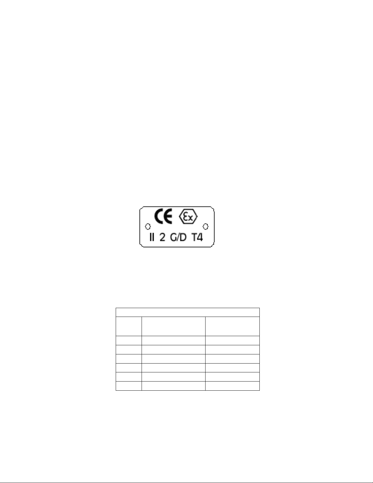
All pumping unit (pump, seal, coupling, motor and pump accessories) certified for use in an ATEX classified
environment, are identified by an ATEX tag secured to the pump or the baseplate on which it is mounted. A
typical tag would look like this:
www.gouldspumps.com/literature_ioms.html or from your local ITT Goulds
The CE and the Ex designate the ATEX compliance. The code directly below these symbols reads as follows:
II = Group 2
2 = Category 2
G/D = Gas and Dust present
T4 = Temperature class, can be T1 to T6 (see Table 1)
Table 1
Max permissible
surface temperature
Code
T1 842 (450) 700 (372)
T2 572 (300) 530 (277)
T3 392 (200) 350 (177)
T4 275 (135) 235 (113)
T5 212 (100) Option not available
T6 185 (85) Option not available
o
F (oC)
The code classification marked on the equipment must be in accordance with the specified area where the
equipment will be installed. If it is not, do not operate the equipment and contact your ITT Goulds Pumps sales
representative before proceeding.
Max permissible
liquid temperature
o
F (oC)
S-7
Page 14
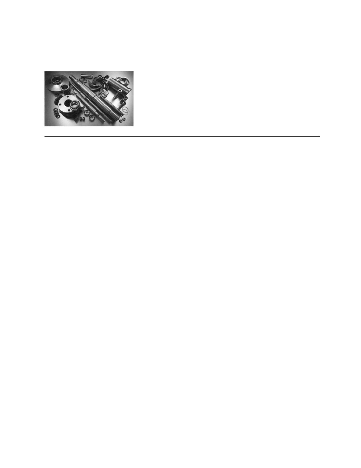
PARTS
The use of genuine Goulds parts will provide the safest and
most reliable operation of your pump. ITT Goulds Pumps ISO
certification and quality control procedures ensure the parts are
manufactured to the highest quality and safety levels.
Please contact your local Goulds representative for details on
genuine Goulds parts.
S-8
Page 15

GENERAL INFORMATION
PUMP DESCRIPTION ................................11
NAMEPLATE INFORMATION ...........................13
RECEIVING THE PUMP ...............................14
PUMP DESCRIPTION
The model is based on 8 bearing configurations and 15 hydraulic sizes. Groupings are as follows:
Group Description Sizes
SX
MX
M
M
(modified)
—
L
LDS
XL
XXL
Ball radial and duplex ball thrust bearings. Flood oil lube with constant level oiler optional grease
lube. Bearing housings bolt to the casing. Goulds non-metallic labyrinth seals.
Ball radial and duplex ball thrust bearings. Flood oil lube with constant level oiler optional grease
lube. Bearing housings bolt to the casing. Goulds non-metallic labyrinth seals.
Ball radial and duplex ball thrust bearings. Ring oil lube with constant level oiler optional grease
lube. Bearing housing secured with tongue and groove fits and a bearing cap with studs and nuts.
Goulds metallic labyrinth seals.
Same as M group except the shaft is longer to accommodate a wider pump.
Ball radial and duplex ball thrust bearings. Ring oil lube with constant level oiler, optional grease
lube. Bearing housing secured with tongue and groove fits and a bearing cap with studs and nuts.
Goulds metallic labyrinth seals.
Double row roller bearings, both thrust and radial. Ring oil lube with constant level oiler, optional
grease lube. Bearing housing secured with tongue and groove fits and a bearing cap with studs
and nuts. Goulds metallic labyrinth seals.
Double row roller bearings, both thrust and radial. Ring oil lube with constant level oiler, optional
grease lube. Bearing housing secured with tongue and groove fits and a bearing cap with studs
and nuts. Goulds metallic labyrinth seals.
Double row roller bearings, both thrust and radial. Ring oil lube with constant level oiler, optional
grease lube. Bearing housing secured with tongue and groove fits and a bearing cap with studs
and nuts. Goulds metallic labyrinth seals.
Double row roller bearings, both thrust and radial. Ring oil lube with constant level oiler, optional
grease lube. Bearing housing secured with tongue and groove fits and a bearing cap with studs
and nuts. Goulds metallic labyrinth seals.
12 x 14-15
16 x 18-17H
18 x 20-20
16 x 18-30
18 x 20-30
20 x 24-24
20 x 24-30
20 x 24-28
18 x 20-24
24 x 30-32
30 x 30-31
30 x 30-38
30 x 36-42
20x30-42
36x42-52
1
The model 3420 is a horizontal between bearings, enclosed
impeller double suction centrifugal pump.
Casing - The casing is horizontally split. The upper and
lower halves are held together with studs and nuts and/or
capscrews. Flanged suction and discharge connections are
located in the lower half of the casing and conform to ANSI
16.1/16.5 class 125/150. The casing is supported by
integrally cast feet. Separate bearing housings are attached
directly to machined fits in each end of the casing with
capscrews or machined fits secured with bearing caps and
studs and nuts. All sizes have dual volute casings to reduce
radial loads on the shaft. The casings are standard with two
jacking screws, two lifting lugs for the upper half, two
tapered dowel pins for alignment, and a .030 or .016 in. (.75
or .41 mm) non-asbestos parting gasket. The upper half is
3420 IOM 8/09 7
provided with a vent connection, a priming connection, and
one or two stuffing box seal ring connections. The lower half
is provided with two drain connections, suction and
discharge gauge connections, and stuffing box overflow
connections.
Impeller - The impeller is an enclosed, double suction design
providing axial hydraulic balance. All exterior surfaces are
fully machined. The impeller receives a one or two plane spin
balance as standard. The impeller is keyed to the shaft and
held in place using shaft sleeves and sleeve nuts.
Wear Rings - Casing and impeller wear rings are supplied as
standard to maintain proper running clearances and to
minimize leakage between the suction and discharge
chambers in the casing. Each casing ring is held in place with
Page 16

a machined hook lock. The impeller rings are held in place
using axial set screws.
Shaft - The shaft is a heavy duty design that minimizes
deflection and vibration. The shaft deflection is a maximum
of .002 in (.051 mm) at the stuffing box face under the worst
operating conditions. The shaft is completely dry with O-ring
seals between the impeller and shaft sleeves and the shaft
sleeves and the sleeve nuts. The standard shaft is AISI 4340
steel with an option for 316 stainless steel.
Shaft Sleeves - Shaft sleeves are standard on all pumps. They
are keyed to the shaft at the impeller and held in place using
sleeve nuts. The sleeve nuts tighten against rotation and are
secured in place with set screws.
Stuffing Box - Non-asbestos packing is standard. The
stuffing box contains a Teflon™ split lantern ring and
renewable stuffing box throat bushings. Tapped openings are
provided for water sealing from either the pump casing or an
outside source. Bypass piping is optional. Two-piece
machined split glands are standard on all packed pumps.
Mechanical Seals - Mechanical seals can be supplied as a
non-standard option. Most seal designs fit in the standard
stuffing box. Goulds does not have its own design gland, so
the gland must be supplied by the seal manufacturer.
Bearings - There are many different bearing configurations
that are offered on the 3420. Specific configurations are
dependent on pump size and group and purchased setup.
Grease lubricated ball, grease lubricated roller, flood oil
lubricated ball, ring oil lubricated ball, and ring oil lubricated
roller bearings are used on various sizes. Oil lubrication is
standard with grease optional. The bearing housings are
sealed with machined labyrinth seals or lip seals.
Baseplates - Fabricated steel bases are standard with a drip
collection chamber and a tapped drain connection. The base
is designed to be grouted and has grout and vent holes.
Soleplates for the pump only or motor only are offered as an
option.
8 3420 IOM 8/09
Page 17
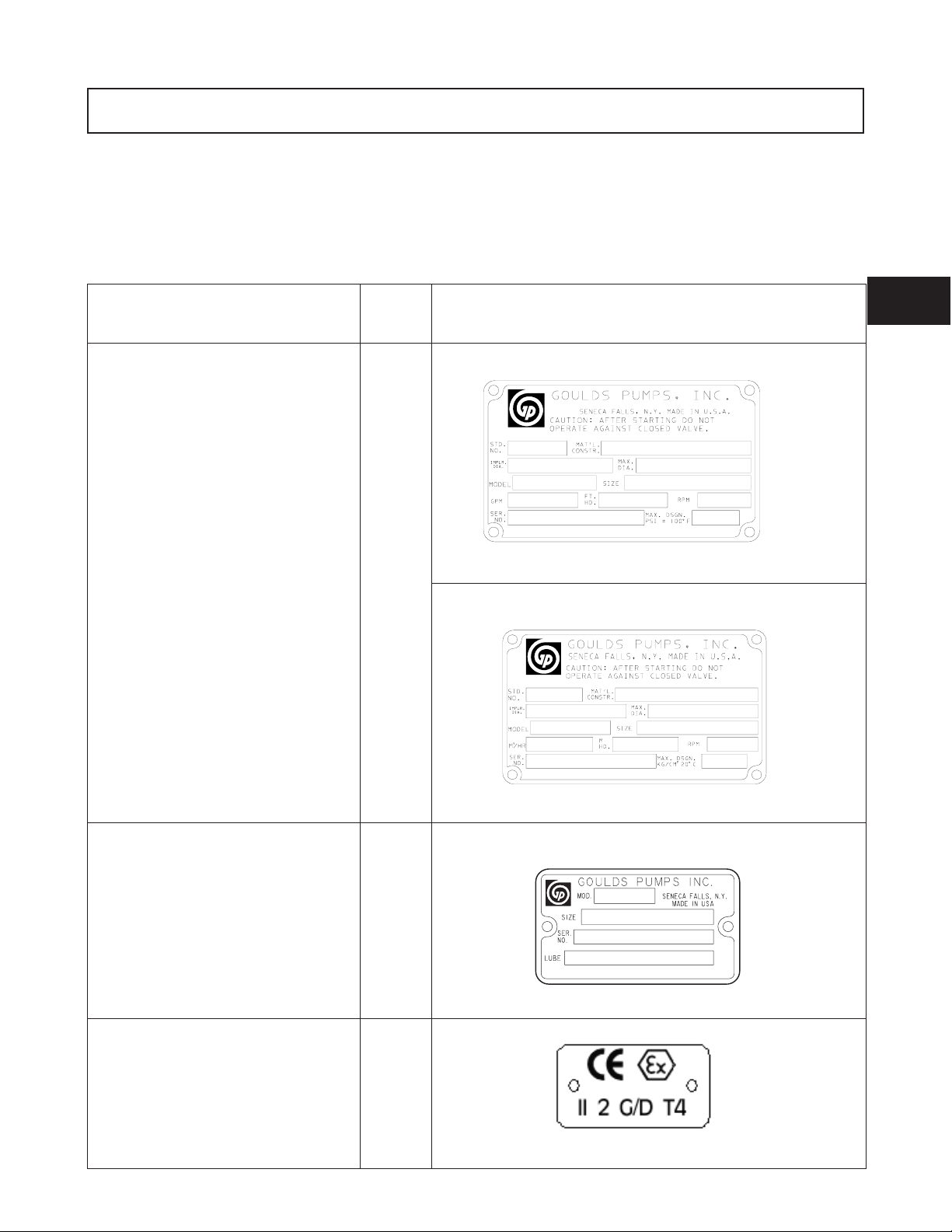
NAMEPLATE INFORMATION
Every pump has two or three Goulds nameplates that provide
information about the pump. The tags are located on the
upper half and lower half of the casing.
Description Fig. No. Example
Pump Casing Tag - provides information
about the pump’s hydraulic
characteristics. Note the format of the
pump size: Discharge x Suction - Nominal
maximum Impeller Diameter in inches.
(Example: 2x3-8)
(Figs.1&2).
Fig. 1
English
When ordering parts, you will need to identify the pump
model, size, serial number, and the item number of the
required parts. Information can be taken from the pump
casing tags. Item numbers can be found later on in this
manual.
1
Bearing Frame Tag - provides
information on the lubrication system used
(Fig. 3).
ATEX Tag - If applicable, your pump
unit may have the following ATEX tag
affixed to the pump and/or baseplate. See
the Safety section for a description of the
symbols and codes
(Fig. 4).
Fig. 2
Metric
Fig. 3
Fig. 4
3420 IOM 8/09 9
Page 18
RECEIVING THE PUMP
Inspect the pump as soon as it is received. Carefully check
that everything is in good order. Make notes of damaged or
missing items on the receipt and freight bill. File any claims
with the transportation company as soon as possible.
Storage Requirements
Short Term: (Less than 6 months): Goulds normal
packaging procedure is designed to protect the pump during
shipping. Upon receipt, store in a covered and dry location.
Long Term: (More than 6 months): Preservative treatment of
bearings and machined surfaces will be required. Rotate shaft
several times every three months. Refer to driver and
coupling manufacturers for their long term storage
procedures. Store in a covered dry location.
Note: Long term storage treatment can be purchased
with the initial pump order.
HANDLING
! WARNING
s
Pump and components are heavy. Failure to properly lift
and support the equipment could result in serious
physical injury, or damage to the pump(s). Steel-toed
shoes must be worn at all times.
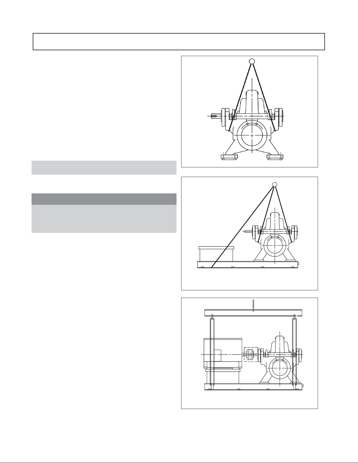
Fig. 3A
Use care when moving pumps. Lifting equipment must be
able to adequately support the entire assembly. Hoist a bare
pump or a pump and soleplate unit using a suitable sling,
under the two bearing housings (Fig. 3A). Baseplate mounted
units without motors are moved by supporting the pump with
a sling under the two bearing housings and a sling under the
motor end of the baseplate (Fig. 3B). Baseplate mounted
units with motors are moved with slings attached to the
baseplate lifting lugs. The use of a spreader bar is required so
that the pump is not damaged (Fig 3C).
Fig. 3B
Fig. 3C
10 3420 IOM 8/09
Page 19
INSTALLATION
SITE/FOUNDATION................................15
BASEPLATE INSTALLATION PROCEDURE .................16
LEVEL BASEPLATE ...............................16
ALIGNMENT AND ALIGNMENT PROCEDURE ...............18
Alignment Check ................................18
Alignment Criteria ...............................18
SetUp......................................19
Measurement ..................................19
Angular Alignment ...............................19
Parallel Alignment ...............................20
Complete Alignment ..............................20
Alignment Trouble Shooting ..........................21
GROUT BASEPLATE ...............................21
Alignment Check ................................21
PIPING........................................21
General .....................................21
Suction Piping .................................22
Discharge Piping ................................22
Final Piping Check ...............................23
3
FOUNDATION
The foundation must be substantial enough to absorb
vibration. (Hydraulic Institute Standards recommends the
foundation weigh at least five [5] times the weight of the
pump unit.) It must form a permanent and rigid support for the
baseplate. This is important in maintaining the alignment of a
flexibly coupled unit.
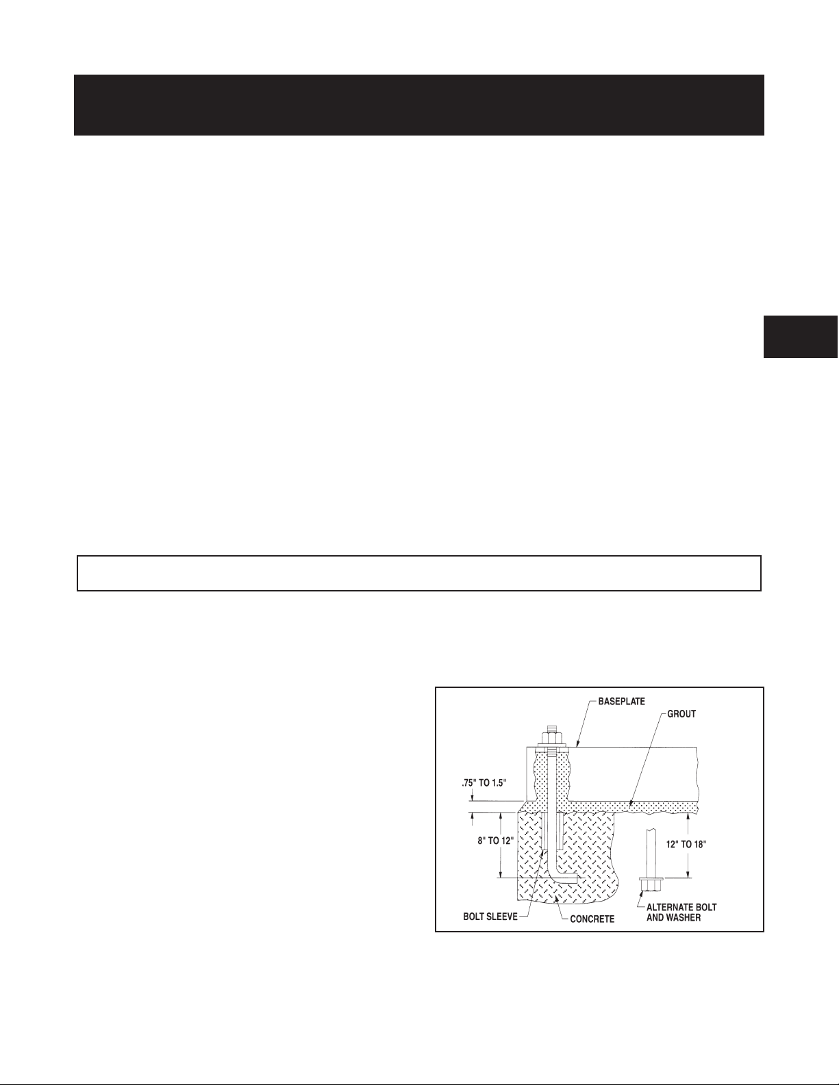
Foundation bolts of the proper size should be embedded in the
concrete to a depth of eight (8) to twelve (12) inches and
locked with either a hook around a reinforcing bar or
alternatively, a nut and washer at the bottom. The bolts should
have a sleeve around them at least six (6) times the bolt
diameter in length and at least two (2) bolt sizes larger in I.D.
If a nut and washer are used for locking, the washer should
have an O.D. two (2) sizes larger than the sleeve. Foundation
bolts should be sized .125" less than the anchor bolt holes in
the base.
The foundation should be poured to within .75" - 1.5" of
the finished height. (See Fig. 4) Freshly poured foundations
should be allowed to cure for several days before the unit is
set in place and grouted.
Fig. 4
3420 IOM 08/09 15
Page 20
BASEPLATE INSTALLATION PROCEDURE
Industry standard procedures and/or the following
procedure should be followed prior to grouting the
baseplate. The procedure assumes the installer has a basic
knowledge of baseplate and foundation design and
installation methods.
BASEPLATE PREPARATION
1. Inspect all surfaces of the baseplate that will contact
the grout for contamination (rust, oil, grime, etc.)
2. Thoroughly clean all surfaces of the baseplate that will
contact the grout with a cleaner that will not leave any
residue.
NOTE: It may be necessary to sandblast the contact
surfaces and coat with a primer compatible with the
grout. If sandblasting is necessary, remove all the
equipment prior to sandblasting.
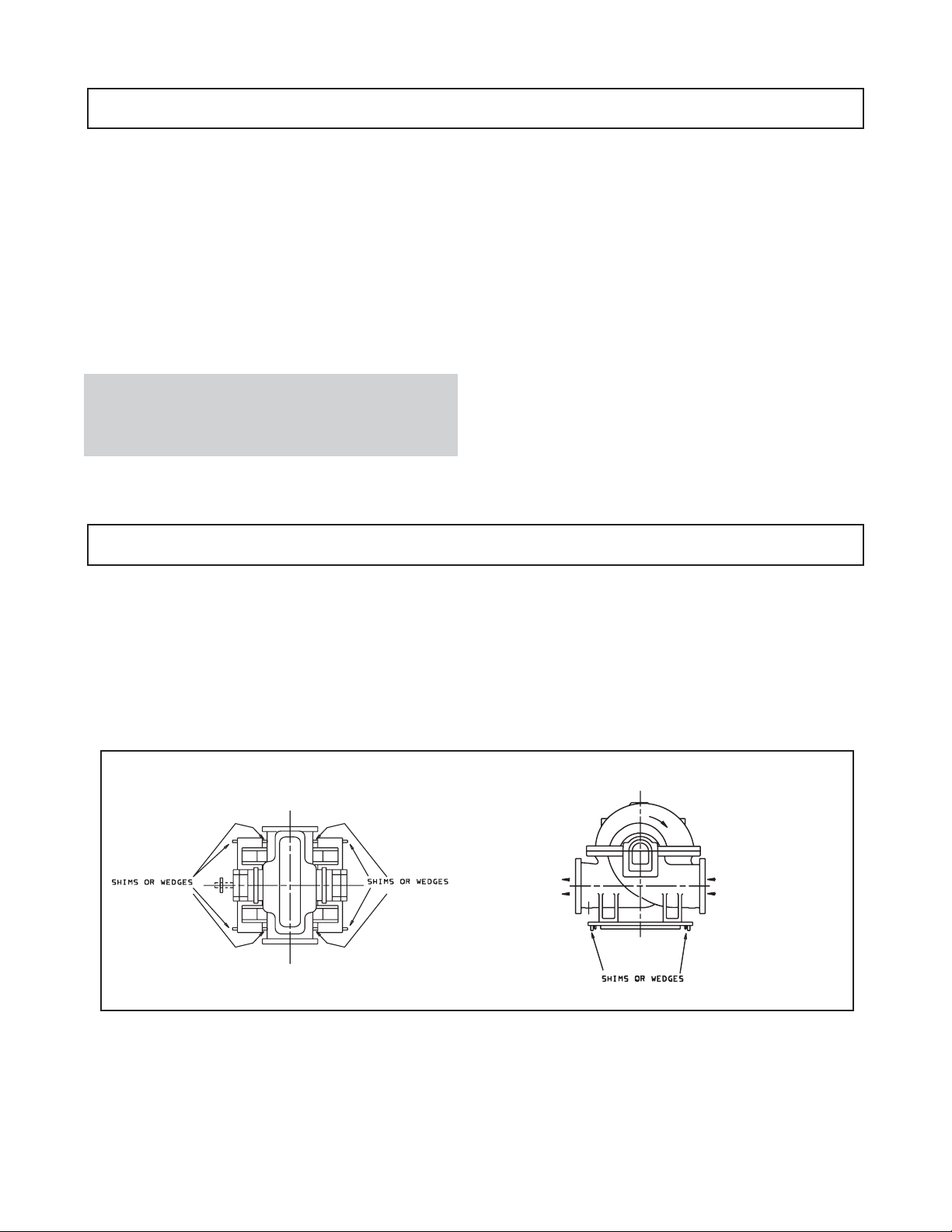
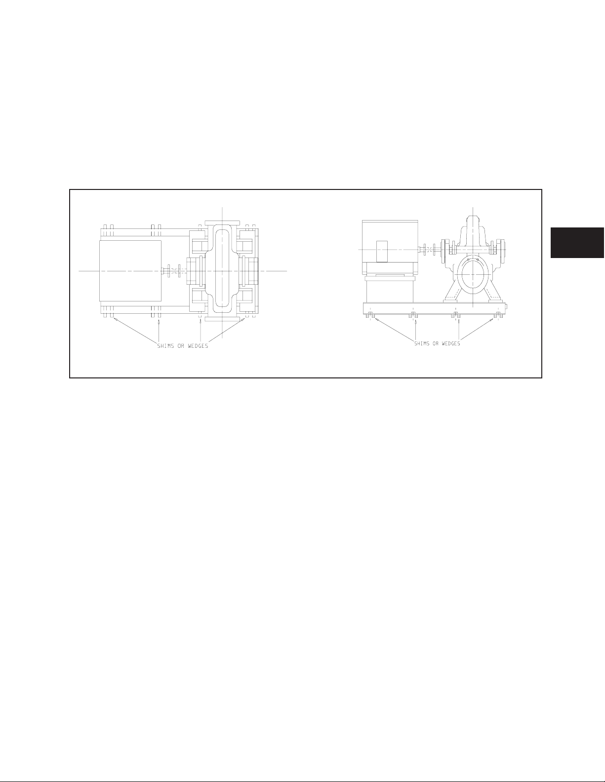
LEVEL BASEPLATE
1. Place two sets of wedges or shims on the foundation,
one set on each side of every foundation bolt. The
wedges should extend .75 in. (20 mm) to 1.5 in. (40
mm) above the foundation to allow for adequate
grouting. This will provide even support for the
baseplate once it is grouted.
3. Inspect all machined surfaces for burrs, rust, paint, or
any other type of contamination. If necessary, use a
honing stone to remove any burrs.
FOUNDATION PREPARATION
1. Chip the top of the foundation .50-1.0 in. (13-25 mm)
to remove porous or low strength concrete. If using a
pneumatic hammer, assure that it is not contaminating
the surface with oil, moisture, etc.
2. Remove water and/or debris from the foundation bolt
holes/sleeves. If sleeve type bolts are being used, fill
the sleeves with stuffing material and seal to prevent
grout from entering.
3. Coat the exposed portion of the anchor bolts with a
non-bonding compound to prevent grout from
adhering to the anchor bolts.
4. If recommended by the grout manufacturer, coat the
foundation surface with a compatible primer.
2. Remove water and/or debris from anchor bolt
holes/sleeves prior to grouting. If sleeve type bolts are
being used, fill the sleeves with rags to prevent grout
from entering.
Fig. 6
16 3420 IOM 08/09
Page 21
3. Carefully lower the baseplate onto the foundation
bolts.
4. Level the baseplate to within .125 in. (3.2 mm) over
the length of the baseplate and to within .088 in. (1.5
mm) over the width of the baseplate by adjusting the
wedges. If the baseplate has vertical leveling screws,
use the screws to level the base.
5. Hand tighten the foundation bolts.
3
Fig. 7
3420 IOM 08/09 17
Page 22
ALIGNMENT AND ALIGNMENT PROCEDURE
Alignment procedures must be followed to prevent
!
unintended contact of rotating parts. Follow
coupling manufacturer’s installation and operation
procedures.
! WARNING
s
Before beginning any alignment procedure, make sure
driver power is locked out. Failure to lock out driver
power may result in serious physical injury.
To remove guard, refer to coupling guard assembly/
disassembly instructions.
The points at which alignment is checked and adjusted are:
Initial Alignment is done prior to operation when the
•
pump and the driver are at ambient temperature.
Final Alignment is done after operation when the
•
pump and driver are at operating temperature.
Alignment is achieved by adding or removing shims from
under the feet of the driver and shifting equipment
horizontally as needed.
Final Alignment (Hot Alignment)
After First Run - To obtain correct alignment when
•
both pump and driver are at operating temperature.
Thereafter, alignment should be checked periodically
in accordance with plant operating procedures.
NOTE: Alignment check must be made if process
temperature changes, piping changes and or pump
service is performed.
ALIGNMENT CRITERIA
Good alignment is achieved when the dial indicator
readings as specified in the alignment procedure are .002
in. (.05 mm) Total Indicated Reading (T.I.R.) or less when
the pump and driver are at operating temperature (Final
Alignment).
During the installation phase, however, it is necessary to
set the parallel alignment in the vertical direction to a
different criteria due to differences in expansion rates of
the pump and driver. Table 1 shows recommended
preliminary (cold) settings for electric motor driven pumps
based on different pumpage temperatures. Driver
manufacturers should be consulted for recommended cold
settings for other types of drivers (steam turbines, engines,
etc.)
NOTE: Proper alignment is the responsibility of the
installer and user of the unit.
Accurate alignment of the equipment must be attained.
Trouble-free operation can be accomplished by following
these procedures.
ALIGNMENT CHECKS
Initial Alignment (Cold Alignment)
Before Grouting Baseplate - To ensure alignment can
•
be obtained.
After Grouting Baseplate - To ensure no changes have
•
occurred during grouting process.
After Connecting Piping - To ensure pipe strains have
•
not altered alignment. If changes have occurred, alter
piping to remove pipe strains on pump flanges.
Table 1
Cold Setting of Parallel
Vertical Alignment
Pumpage Temperature Set Driver Shaft
ambient N/A
100°F
200°F
300°F
.000" - .002" HIGH
.002” - .004” HIGH
.004” - .006” HIGH
18 3420 IOM 08/09
Page 23
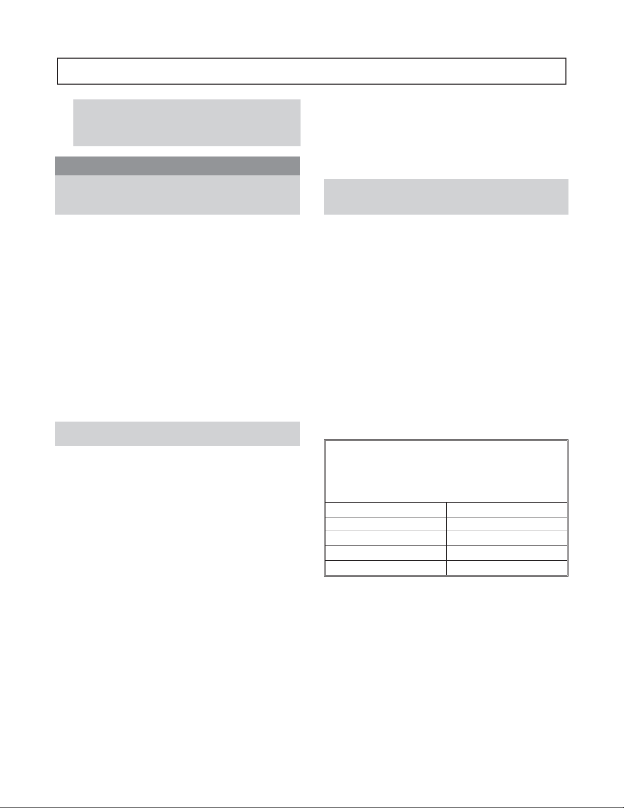
SET UP
1. Mount two dial indicators on the pump coupling half
(X) so they contact the other coupling half (Y) (Figs.
8 & 9).
Fig. 8
Fig. 10
Vertical Correction (Top-to-Bottom)
1. Zero indicator A at top dead center (12 o‘clock) of
coupling half Y.
2. Rotate indicators to bottom dead center (6 o‘clock).
Observe needle and record reading.
3. Negative Reading - The coupling halves are further
apart at the bottom than at the top. Correct by either
raising the driver feet at the shaft end (add shims) or
lowering the driver feet at the other end (remove
shims).
3
Fig. 9
2. Check setting of indicators by rotating coupling half
X to ensure indicators stay in contact with coupling
half Y but do not bottom out. Adjust indicators
accordingly.
MEASUREMENT
1. To ensure accuracy of indicator readings, always
rotate both coupling halves together so indicators
contact the same point on coupling half Y. This will
eliminate any measurement problems due to runout on
coupling half Y.
2. Take indicator measurements with driver feet
hold-down bolts tightened. Loosen hold down bolts
prior to making alignment corrections.
3. Take care not to damage indicators when moving
driver during alignment corrections.
ANGULAR ALIGNMENT
A unit is in angular alignment when indicator A (Angular
indicator) does not vary by more that .002 in. (.05 mm) as
measured at four points 90° apart (Fig. 10).
Positive Reading - The coupling halves are closer at
the bottom than at the top. Correct by either lowering
the driver feet at the shaft end (remove shims) or
raising the driver feet at the other end (add shims).
4. Repeat steps 1-3 until indicator A reads .002 in (.05
mm) or less.
Horizontal Correction (Side-to-Side)
1. Zero indicator A on left side of coupling half Y, 90°
from top dead center (9 o’clock).
2. Rotate indicators through top dead center to the right
side, 180° from the start (3 o’clock). Observe needle
and record reading.
3. Negative Reading - The coupling halves are further
apart on the right side than the left. Correct by either
sliding the shaft end of the driver to the left or the
other end to the right.
Positive Reading - The coupling halves are closer
together on the right side than the left. Correct by
either sliding the shaft end of the driver to the right or
the other end to the left.
4. Repeat steps 1 through 3 until indicator A reads .002
in. (.05 mm) or less.
5. Re-check both horizontal and vertical readings to
ensure adjustment of one did not disturb the other.
Correct as necessary.
3420 IOM 08/09 19
Page 24

PARALLELALIGNMENT
A unit is in parallel alignment when indicator P (parallel
indicator) does not vary by more than .002 in. (.05 mm) as
measured at four points 90° apart at operating temperature.
Note the preliminary vertical cold setting criteria, Table 1.
Vertical Correction (Top-to-Bottom)
1. Zero indicator P at top dead center of coupling (12
o’clock) half Y.
2. Rotate indicator to bottom dead center (6 o‘clock).
Observe needle and record reading.
3. Negative Reading - Coupling half X is lower than
coupling half Y. Correct by removing shims of
thickness equal to half of the indicator reading under
each driver foot.
Positive Reading - Coupling half X is higher than
coupling half Y. Correct by adding shims of thickness
equal to half of the indicator reading from each driver
foot.
NOTE: Equal amounts of shims must be added to or
removed from each driver foot. Otherwise the vertical
angular alignment will be affected.
4. Repeat steps 1 through 3 until indicator P reads within
.002 in. (.05 mm) or less when hot, or per Table 1
when cold.
Horizontal Correction (Side-to-Side)
1. Zero indicator P on the left side of coupling half Y,
90° from top dead center (9 o‘clock).
2. Rotate indicators through top dead center to the right
side, 180° from the start (3 o‘clock). Observe needle
and record reading.
3. Negative Reading - Coupling half Y is to the left of
coupling half X. Correct by sliding driver evenly in
the appropriate direction.
NOTE: Failure to slide motor evenly will affect
horizontal angular correction.
4. Repeat steps 1 through 3 until indicator P reads .002
in. (.05 mm) or less.
5. Re-check both horizontal and vertical readings to
ensure adjustment of one did not disturb the other.
Correct as necessary.
COMPLETE ALIGNMENT
A unit is in complete alignment when both indicators A
(angular) and P (parallel) do not vary by more than .002 in.
(.05 mm) as measured at four points 90 apart.
Vertical Correction (Top-to-Bottom)
1. Zero indicators A and P at top dead center (12
o'clock) of coupling half Y.
2. Rotate indicator to bottom dead center (6 o'clock).
Observe the needles and record the readings.
3. Make corrections as outlined previously.
Horizontal Correction (Side-to-Side)
1. Zero indicators A and P on the left side of coupling
half Y, 90° from top dead center (9 o'clock).
2. Rotate indicators through top dead center to the right
side, 180° from the start (3 o‘clock). Observe the
needle, measure and record the reading.
3. Make corrections as outlined previously.
4. Recheck both vertical and horizontal readings to
ensure adjustment of one did not disturb the other.
Correct as necessary.
NOTE: With experience, the installer will understand
the interaction between angular and parallel and will
make corrections appropriately.
Positive Reading - Coupling half Y is to the right of
coupling half X. Correct by sliding driver evenly in
the appropriate direction.
20 3420 IOM 08/09
Page 25
ALIGNMENT TROUBLESHOOTING
Problem Probable Cause Remedy
Driver feet bolt bound.
Cannot obtain horizontal (Side-to-Side)
alignment, angular or parallel
Cannot obtain vertical (Top-to-Bottom)
alignment, angular or parallel
Baseplate not leveled properly, probably
Baseplate not leveled properly,
probably bowed.
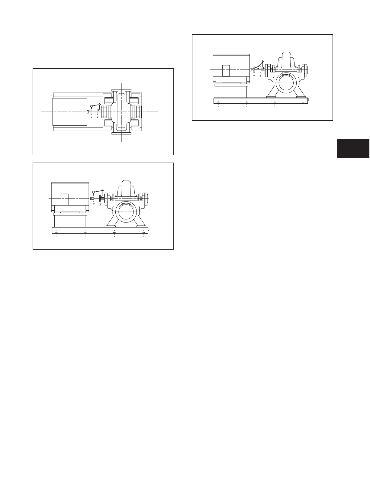
GROUT BASEPLATE
1. Clean areas of baseplate that will contact grout. Do
not use oil-based cleaners because grout will not bond
to it. Refer to grout manufacturers instructions.
2. Build dam around foundation. Thoroughly wet
foundation (Fig. 11).
3. Pour grout through grout hole in baseplate, up to level
of dam. Remove air bubbles from grout as it is poured
by puddling, using a vibrator, or pumping the grout
into place. Non-shrink grout is recommended.
twisted.
Loosen pump hold-down bolts and slide
pump and driver until horizontal alignment is
achieved.
Determine which corner(s) of the baseplate
are high or low and remove or add shims at
the appropriate corner(s) and realign.
Determine if center of baseplate should be
raised or lowered and correct by evenly add
ing or removing shims at the center of the
baseplate.
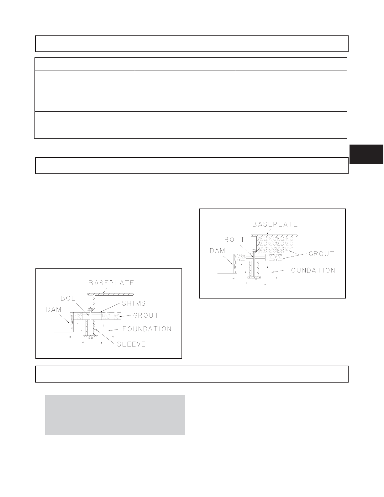
4. Allow grout to set.
5. Fill remainder of baseplate with grout. Remove air as
before (Fig. 12).
-
3
Flange loads from the piping system, including
!
those from thermal expansion of the piping, must
not exceed the limits of the pump. Casing
deformation can result in contact with rotating parts
and result in excess heat generation, sparks and
premature failure.
Fig. 11
Fig. 12
6. Allow grout to set at least 48 hours.
7. Tighten foundation bolts.
ALIGNMENT CHECK
Re-check alignment before continuing, using methods
previously described.
PIPING
GENERAL
Guidelines for piping are given in the “Hydraulic Institute
Standards” available from: Hydraulic Institute, 30200
Detroit Road, Cleveland, OH 44145-1967 and must be
reviewed prior to pump installation.
3420 IOM 08/09 21
Page 26

A
! WARNING
s
Never draw piping into place by forcing at the flanged
connections of the pump. This may impose dangerous
strains on the unit and cause misalignment between
pump and driver. Pipe strain will adversely effect the
operation of the pump resulting in physical injury and
damage to the equipment.
1. All piping must be supported independently of, and
line up naturally with, the pump flanges.
2. Piping runs should be as short as possible to minimize
friction losses.
3. DO NOT connect piping to pump until grout has
hardened and pump and driver hold-down bolts have
been tightened.
4. It is suggested that expansion loops or joints be
properly installed in suction and/or discharge lines
when handling liquids at elevated temperatures, so
linear expansion of piping will not draw pump out of
alignment.
! WARNING
s
All expansion joints should be properly supported,
anchored, and restrained. Failure to do so may result
in serious physical injury if the expansion joint fails.
5. The piping should be arranged to allow pump flushing
prior to removal of the unit on services handling
corrosive liquids.
6. Carefully clean all pipe parts, valves and fittings, and
pump branches prior to assembly.
straight pipe between the elbow and the pump suction
flange.
3. Use suction pipe one or two sizes larger than the
pump suction, with a reducer at the suction flange.
Suction piping should never be of smaller diameter
than the pump suction.
4. Reducers, if used, should be eccentric, at the pump
suction flange, with sloping side down.
5. Pump must never be throttled on suction side.
6. Suction strainers, when used, must have a net “free
area” of at least three times the suction pipe area.
7. Separate suction lines are recommended when more
than one pump is operating from the same source of
supply.
Suction Lift Conditions
1. Suction pipe must be free from air pockets.
2. Suction piping must slope upwards to pump.
3. All joints must be air tight.
4. A means of priming the pump must be provided, such
as a foot valve.
Suction Head/Flooded Suction Conditions
1. An isolation valve should be installed in the suction
line at least two pipe diameters from the suction to
permit closing of the line for pump inspection and
maintenance.
2. Keep suction pipe free from air pockets.
3. Piping should be level or slope gradually downward
from the source of supply.
SUCTION PIPING
! WARNING
s
NPSHAmust always exceed NPSHRas shown on Goulds
performance curves received with order. Reference
Hydraulic Institute for NPSH and pipe friction values
needed to evaluate suction piping.
Properly installed suction piping is a necessity for
trouble-free pump operation. Suction piping should be
flushed BEFORE connection to the pump.
1. Use of elbows close to the pump suction flange should
be avoided. There should be a minimum of two pipe
diameters of straight pipe between the elbow and
suction inlet. Where used, elbows should be long
radius.
2. If an elbow must be used at the suction flange, it must
be in the vertical position only. If an elbow must be
used in other than a vertical position, it is permissable
only by providing a minimum of two diameters of
4. No portion of the piping should extend below pump
suction flange.
5. The size of entrance from supply should be one or two
sizes larger than the suction pipe.
6. The suction pipe must be adequately submerged
below the liquid surface to prevent vortices and air
entrainment at the supply.
DISCHARGE PIPING
1. Isolation and check valves should be installed in
discharge line. Locate the check valve between
isolation valve and pump, this will permit inspection
of the check valve. The isolation valve is required for
priming, regulation of flow, and for inspection and
maintenance of pump. The check valve prevents
pump or seal damage due to reverse flow through the
pump when the driver is turned off.
2. Increasers, if used, should be placed between pump
and check valves.
22 3420 IOM 08/09
Page 27

3. Cushioning devices should be used to protect the
pump from surges and water hammer if quick- closing
valves are installed in system.
FINAL PIPING CHECK
After connecting the piping to pump:
1. Rotate shaft several times by hand to be sure that
there is no binding and all parts are free.
2. Check alignment, per the alignment procedure
outlined previously to determine absence of pipe
strain. If pipe strain exists, correct piping.
3
3420 IOM 08/09 23
Page 28

24 3420 IOM 08/09
Page 29

OPERATION
PREPARATION FOR START-UP ..........................25
Check Rotation ...................................25
Couple Pump and Driver ..............................25
Lubricating Bearings ................................26
Shaft Sealing ....................................27
Priming Pump ...................................29
STARTING PUMP ...................................31
OPERATION ......................................31
General Considerations...............................31
Operating at Reduced Capacity ..........................31
Operating Under Freezing Conditions .......................32
SHUTDOWN ......................................32
FINAL ALIGNMENT .................................32
PREPARATION FOR START-UP
When installing in a potentially explosive
!
environment, ensure that the motor is properly
certified.
4
4. Make sure everyone is clear. Jog driver just long
enough to determine the direction of rotation. The
rotation must correspond to the arrow on the pump
casing.
CHECK ROTATION
1. Lock out power to the driver.
! WARNING
s
Lock out driver power to prevent accidental start-up
and physical injury.
All equipment being installed must be properly
!
grounded to prevent unexpected static electric
discharge.
2. Make sure the coupling hubs are securely fastened to
the shafts.
! WARNING
s
Do not jog a coupled pump.
$
Serious injury may result if pump is run in the wrong
direction.
CAUTION
5. Lock out the power to the driver.
COUPLE PUMP & DRIVER
! WARNING
s
Lock out driver power to prevent accidental rotation
and physical injury.
1. Install and lubricate the coupling per the
manufacturer’s instructions.
The coupling used in an ATEX classified
!
environment must be properly certified.
NOTE: Pump is shipped with the coupling hubs
disconnected.
3. Unlock driver power.
3420 IOM 8/09 25
Page 30
2. Install the coupling guard (Fig. 13). Refer to the
Coupling Guard Installation and Disassembly Section
(Appendix I).
The coupling guard used in an ATEX classified
!
environment must be constructed from a
non-sparking material.
! WARNING
s
Never operate a pump without the coupling guard
installed. Personal injury will occur if the pump is run
without the coupling guard.
Leakage of process liquid may result in creating an
!
explosive atmosphere. Ensure the materials of the
pump casing, impeller, shaft, sleeves, gaskets and
seals are compatible with the process liquid.
A build up of gases within the pump, sealing system
!
and or process piping system may result in an
explosive environment within the pump or process
piping system. Ensure process piping system, pump
and sealing system are properly vented prior to
operation.
LUBRICATING BEARINGS
Bearings must be lubricated properly in order to
!
prevent excess heat generation, sparks and
premature failure.
Cooling systems such as those for bearing
!
lubrication, mechanical seal systems, etc, where
provided, must be operating properly to prevent
excess heat generation, sparks and premature
failure.
Rotate shaft by hand to ensure it rotates smoothly
!
and there is no rubbing which could lead to excess
heat generation and or sparks.
Ensure that pump and systems are free of foreign
!
objects before operating and that objects cannot
enter the pump during operation. Foreign objects in
the pumpage or piping system can cause blockage of
flow which can result in excess heat generation,
sparks and premature failure.
Fig. 13
$
Pumps are shipped without oil.
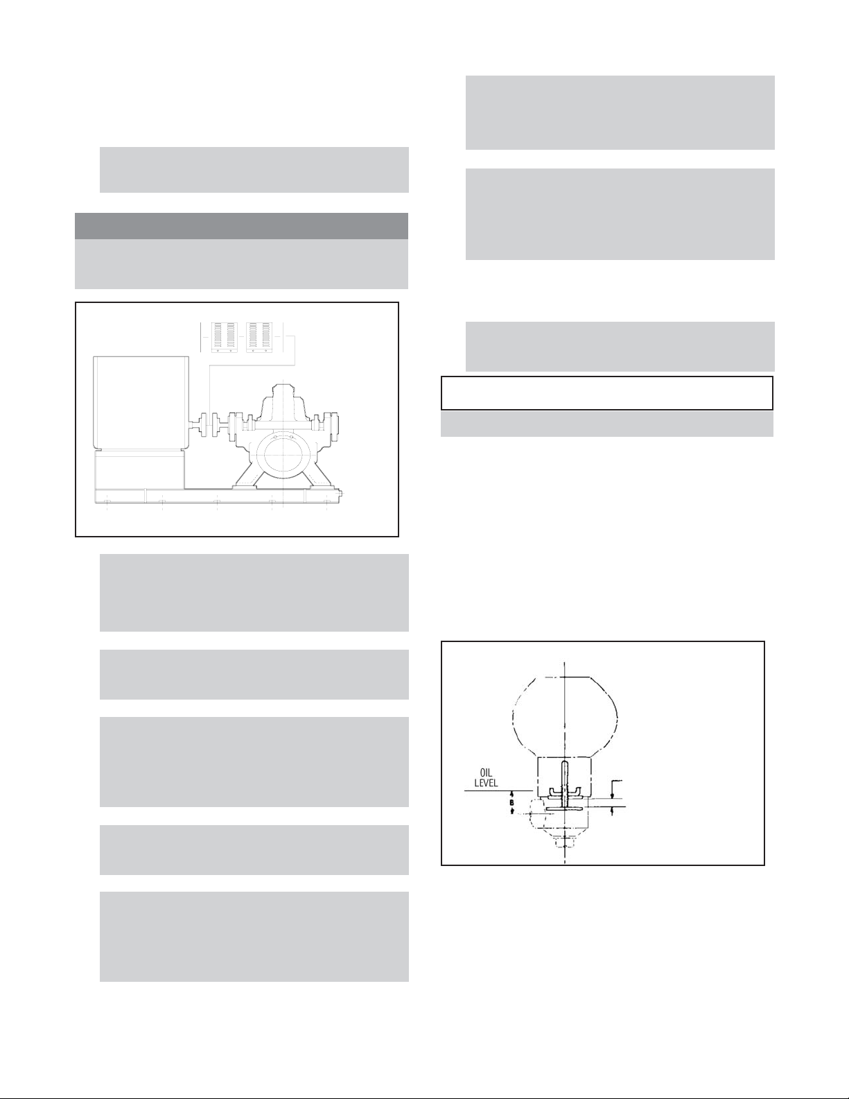
Oil Lubrication: Oil lubricated pumps are not lubricated at
the factory. Constant level oilers are supplied with oil
lubricated pumps. The oiler can be found in the box of
fittings that accompanied the pump during shipment. The
oiler was adjusted to maintain the proper oil level before
leaving the factory. The adjustment should be checked in
case the setting was disturbed during shipment. See Figure
14. The correct dimensions for A and B are given in Table
2. Fill the bearing housing with oil using the oil bottle.
Continue to refill the oil bottle until oil stops draining from
the oiler into the housing. See Table 4 for recommended
oil.
CAUTION
Instructions
1. Remove adjustment
assembly from oiler.
2. Adjust bars to dim. "A".
3. Lock in position.
4. Replace adjust. assem. in
oiler
A
Do not insulate bearing housings as this can result
!
in excess heat generation, sparks and premature
failure.
Check for magnetism on the pump shaft and
!
degauss the shaft if there is any detectable
magnetism. Magnetism will attract ferritic objects to
the impeller, seal and bearings which can result in
excess heat generation, sparks and premature
failure.
Pure/Purge Oil Mist: For pure oil mist, connect the oil
mist system according to the manufacturer's
recommendations. For purge oil mist, connect the oil mist
system per the manufacturers instructions. Fill the pump
with oil as detailed for oil lubrication above. In both cases,
refer to the pump dimensional drawing for the location of
the oil mist connections to the bearing housings. See Table
2 for oil bottle settings and Table 4 for recommended oil.
Fig. 14
26 3420 IOM 8/09
Page 31

Group Sizes
Table 2
Oil Settings - Inches (mm)
Flood Oil Ball / Ring Oil Ball / Ring Oil Roller
Oiler Size “A” in (mm) “B” in (mm)
SX
MX 18 x 20-20
M
M
Modified
- 18 x 20-24
L 24 x 30-32
LDS
XL
XXL 36x42-52
12 x 14-15
16 x 18-17H
16 x 18-30
18 x 20-30
20 x 24-24
20 x 24-30
20 x 24-28
30 x 30-31
30 x 30-38
30 x 36-42
20x30-42
Grease Lubrication: Pumps are shipped with grease
installed, sufficient for 2,000 hours operation. It is
recommended that additional or replacement lubrication be
added after every 2,000 hours or at three month intervals.
The lubricant should be renewed in the housings at least
once each year. See Table 5 (p. 35) for recommended
greases.
If the pump is put into operation after a prolonged
shut-down, flush out the bearing housings with a light oil
to remove any contaminants. During flushing, rotate the
shaft slowly by hand. Finally, flush the bearing housing
with the proper lubricating oil to ensure oil quality after
cleaning.
#3
4 OZ.
#3
4 OZ.
#10
16 OZ.
#10
16 OZ.
#10
16 OZ.
#10
16 OZ.
#10
16 OZ.
#10
16 OZ.
#10
16 OZ.
27/32 (21.4) 3/4 (19)
27/32 (21.4) 3/4 (19)
9/16 (14.3) 1/2 (12.7)
27/32 (21.4) 3/4 (19)
27/32 (21.4) 3/4 (19)
7/8 (22.2) 13/16 (20.6)
9/16 (14.3) 1/2 (12.7)
9/16 (14.3) 1/2 (12.7)
3/8 (9.7) 7/16 (11.1)
the box of fittings shipped with the pump and must be
installed before start-up.
Installation of Packing:
1. Carefully clean the stuffing box bore.
2. Twist the packing just enough to get it around the
shaft (Fig 15).
4
! WARNING
s
Operation of the unit without proper lubrication will
cause bearing failure and pump seizure.
SHAFT SEALING
Packed stuffing boxes are not allowed in an ATEX
!
classified environment.
Packed Stuffing Box: Pumps are shipped without packing,
lantern ring, or split gland installed. These are included in
3420 IOM 8/09 27
3. Insert packing, staggering the joints in each ring by
90° degrees.
Fig. 15
Page 32

4. Use a wooden split bushing to properly seat the first
two rings of packing. See Fig 16.
Fig. 16
5. The stuffing box arrangement in order of installation
is: two packing rings, lantern ring, then three packing
rings. See Fig. 17.
pressure for clean pumpages. For an abrasive pumpage, the
2
flush water pressure should be 30-50 psi (2.1-3.5 kg/cm
)
above the suction pressure.
NOTE: A product flush can be used if a clean
pumpage exists.
NOTE: Most packing requires lubrication. Failure to
lubricate the packing may shorten the life of the
packing and the pump.
Fig. 17
$
CAUTION
Follow instructions to ensure the lantern ring is
located at the flushing connection. Otherwise, no
flush will be obtained.
6. Install the gland halves. Bolt the gland halves together
and mount on gland studs. Tighten gland nuts.
Connection of Sealing Liquid: If the stuffing box pressure
is above atmospheric pressure and the pumpage is clean,
normal gland leakage of 40-60 drops per minute is usually
sufficient to lubricate and cool the packing. Sealing liquid
then, is not required.
An external sealing liquid is required when:
1. Abrasive particles in the pumpage could score the
shaft sleeve.
2. Stuffing box pressure is below atmospheric pressure
due to the pump running with suction lift or when the
suction source is under a vacuum. Under these
conditions, packing will not be cooled and lubricated
and air will be drawn into the pump.
If an outside source of clean compatible liquid is required,
the pressure should be 15 psi (1.0 kg/cm
2
) above the suction
28 3420 IOM 8/09
Page 33

PRIMING THE PUMP
Never start the pump until it has been properly primed.
Several different methods of priming can be used,
depending on the type of installation and service involved.
Suction Supply Below Pump
A. Priming with a Foot Valve - With the pump installed on
a suction lift and with a foot valve at the end of the suction
line, priming can be done any of the following three ways:
Pumps must be fully primed at all times during
!
operation.
! WARNING
s
If the pump is run dry, rotating parts within the pump
may seize to non-moving parts. This may result in
serious physical injury.
Suction Supply Above Pump
When the pump is installed as shown in Fig. 18, the pump
will prime itself.
Fig. 18
Outside Supply (Fig. 19)
4
Fig. 19
1. Close the discharge valve.
2. Remove the vent plugs or open the vent valves on the
top of the pump and the two suction lobes.
1. Close the discharge valve.
2. Open the suction valve.
3. Remove the vent plugs or open the vent valves on the
top of the pump and the two suction lobes until all air
is expelled and fluid flows through the openings.
4. Replace the vent plugs or close the vent valves.
5. Start the pump and open the discharge valve.
The pump will continue to be primed for any future
starting. This method is the simplest and, particularly for
automatic operation, the safest. A float switch in the
suction reservoir can be arranged to stop the pump, should
the liquid supply fall below minimum levels.
3. Open the valve in the priming supply line. Fill the
pump until all air is expelled and fluid flows through
the vents.
4. Replace the vent plugs or close the vent valves and
close the valve in the priming supply line.
5. Start the pump and open the discharge valve.
The pump will continue to be primed for any future
starting.
3420 IOM 8/09 29
Page 34

Priming with a Separate Hand or Manually Controlled
Priming Pump (Fig. 20)
Fig. 20
1. Close the discharge valve.
2. Open the valve in the priming line.
Priming by Bypassing Around the Discharge Check
Valve (Fig. 21)
NOTE: This method can only be used when there is
liquid under some pressure in the discharge line. The
original prime must be effected from some outside
source.
Fig. 21
3. Exhaust the air from the pump and the suction piping
until water flows from the priming pump.
4. Close the valve in the priming line.
5. Shutoff the priming pump.
6. Start the pump and open the discharge valve.
1. Close the discharge valve.
2. Remove the vent plugs or open the vent valves on the
top of the pump and the two suction lobes.
3. Open the valve in the check valve bypass line.
4. Exhaust the air from the pump and the suction piping
until water flows from vent connections.
5. Replace the vent plugs or close the vent valves and
close the valve in the bypass line.
6. Start the pump and open the discharge valve.
30 3420 IOM 8/09
Page 35

Priming with an Ejector (Fig. 22)
1. Close the discharge valve.
On suction lift applications, an ejector (operated by steam,
compressed air, or pressurized water) connected to the top
of the casing (priming or vent connection) can be used to
remove air from the casing and suction line, thus priming
the pump.
Fig. 22
STARTING PUMP
1. Make sure the suction valve and any recirculation or
cooling lines are open.
2. Open the ejector supply valve in the steam, air, or
water line, valve “E”.
3. Open the priming isolation valve, “S”.
4. Once the unit is primed, close the priming isolation
valve, “S”.
5. Close the ejector supply valve, “E”.
6. Start the pump and open the discharge valve.
4
4. Slowly open the discharge valve until the desired flow
is obtained.
2. Fully close or partially open the discharge valve as
dictated by system conditions.
3. Start the driver.
$
Immediately observe the pressure gauges. If the
discharge pressure is not quickly attained, stop the
driver, reprime, and attempt to restart.
CAUTION
OPERATION
GENERAL CONSIDERATIONS
Always vary the capacity by regulating the discharge valve.
NEVER throttle the flow from the suction side.
The driver may overload if the pumpage specific gravity
(fluid density) is greater than originally stated or if the flow
rate is exceeded.
Always operate the pump at or near the rated conditions to
prevent damage resulting from cavitation or recirculation.
$
Observe the pump for vibration levels, bearing
temperature, and excessive noise. If normal levels are
exceeded, shut down the pump and troubleshoot the
problem.
CAUTION
OPERATING AT REDUCED CAPACITY
! WARNING
s
DO NOT operate the pump below the minimum rated
flow or with the suction and/or discharge valves closed.
These conditions may create an explosive hazard due to
vaporization of the pumpage. This can quickly lead to
pump failure and physical injury. Refer to Appendix II
for the pump's minimum flow.
Damage occurs from:
1. Increased vibration levels - This affects the bearings,
stuffing box, and mechanical seal (if supplied).
3420 IOM 8/09 31
Page 36

2. Increased radial loads - Increases stress on the shaft
and increases loads on the bearings.
3. Heat build up - Vaporization of the pumpage may
cause the rotating parts to score or seize.
4. Cavitation - Damages the internal surfaces of the
pump.
SHUTDOWN
OPERATING UNDER FREEZING
CONDITIONS
Exposure to freezing conditions, while the pump is idle,
could cause the liquid to freeze and damage the pump.
Liquid inside the pump should be drained. Liquid inside
cooling coils, if supplied, should also be drained.
1. Slowly close the discharge valve.
2. Shut down and lock out the driver to prevent
accidental rotation.
! WARNING
s
Lock out driver power to prevent accidental rotation
and physical injury.
FINAL ALIGNMENT
1. Run the unit under actual operating conditions for a
sufficient length of time to bring the pump and driver
up to the normal operating temperature.
! WARNING
s
When handling hazardous and/or toxic fluids, proper
personal protective equipment should be worn. If the
pump is being drained, precautions must be taken to
prevent physical injury. The pumpage must be handled
and disposed of in conformance with the applicable
environmental regulations.
2. Check the alignment while the unit is at the normal
operating temperature per the alignment procedure in
Section 3.
3. Reinstall the coupling guard. Refer to the coupling
guard instructions in Appendix I.
32 3420 IOM 8/09
Page 37

PREVENTIVE MAINTENANCE
GENERAL COMMENTS ...............................33
MAINTENANCE SCHEDULE ............................33
MAINTENANCE OF BEARINGS ..........................34
Oil Lubricated Bearings ..............................34
Grease Lubricated Bearings ............................35
Bearing Removal ..................................36
MAINTENANCE OF SHAFT SEALS ........................37
Mechanical Seals ..................................37
Packed Stuffing Box ................................37
TROUBLE SHOOTING ................................38
GENERAL COMMENTS
A routine maintenance program can extend the life of your pump. Well maintained equipment
will last longer and require fewer repairs. You should keep maintenance records. This will help pinpoint
potential causes of problems.
The preventive maintenance section must be adhered to in order to keep the applicable ATEX classification of the
!
equipment. Failure to follow these procedures will void the ATEX classification for the equipment.
MAINTENANCE SCHEDULE
INSPECTION INTERVALS
Inspection intervals should be shortened appropriately if
the pumpage is abrasive and/or corrosive,
or if the environment is classified as potentially
!
explosive.
ROUTINE MAINTENANCE
Bearing lubrication
•
Seal Monitoring
•
Vibration Analysis
•
Discharge Pressure Monitoring
•
ROUTINE INSPECTIONS
Check the level and the condition of the oil
•
Check for unusual noise, vibration, and bearing
•
temperatures
Inspect the pump and piping for leaks
•
Check the seal chamber/stuffing box leakage
•
Mechanical Seal - There should be no leakage.
•
Packing - Excessive leakage requires adjustment
•
or possible packing replacement. Refer to sec
tion 4: Operation, for packing gland adjustment.
-
5
Temperature Monitoring
•
3420 IOM 8/09 33
Page 38

THREE MONTH INSPECTIONS
Check foundation and hold-down bolts for tightness.
•
If the pump has been left idle, check the packing.
•
Replace, if required.
Oil should be changed every three months (2,000 hrs)
•
or more often if there are any adverse atmospheric
conditions or other conditions that may contaminate
or break-down the oil. Change the oil whenever it
appears cloudy or contaminated.
MAINTENANCE OF BEARINGS
Bearings must be lubricated properly in order to
!
prevent excess heat generation, sparks and
premature failure.
OIL LUBRICATED BEARINGS
! WARNING
s
Pumps are shipped without oil. Oil lubricated bearings
must be lubricated at the jobsite.
Change the oil after 200 hours for new bearings.
Thereafter, change the oil every 2,000 hours or three
months, whichever comes first.
Check the shaft alignment. Re-align if required.
•
ANNUAL INSPECTIONS
Check the pump capacity, pressure, and power. If the
•
pump performance does not satisfy your process
requirements and your process requirements have not
changed, the pump should be disassembled,
inspected, and the worn parts replaced. Otherwise, a
system inspection should be done.
Ring oil or flood oil lubricated anti-friction bearings are
standard on all model 3420 pumps. Oil lubricated pumps
are supplied with oilers which maintain a constant oil level
in the bearing housings. Each oiler should be installed and
the pump lubricated as follows:
1. Check the oiler adjustment prior to installing the oiler,
refer to Table 2 for the proper oiler setting.
2. Install one oiler in each bearing housing.
$
Do not fill the bearing housings with oil through any
connection other than the oiler connection. This can
result in an improper oil level which may shorten the
life of the bearings and cause damage to the pump.
!CAUTION
Bearing
Arrangement
Flood Oil Ball Bearing
Ring Oil Ball Bearing
Ring Oil Roller Bearing
Table 3
Bearings and Oil Requirements
Oil Volume Required
Group Sizes
Bearing Size
(per each housing)
Thrust Radial mL pints
SX
MX 18 x 20-20 7316 6316
M
M (modified) 20 x 24-28 7321 6321 1350 2.85
-
L 24 x 30-32 22226 1700 3.60
LDS
XL
XXL 36x42-52 22240 4350 9.2
12 x 14-15
16 x 18-17H radial = 580 radial = 1.23
16 x 18-30
18 x 20-30
20 x 24-24
20 x 24-30
18 x 20-24 7318 6318 620 1.32
30 x 30-31
30 x 30-38
30 x 36-42
20x30-42
7313 6313
7321 6321 1170 2.47
22228 1720 3.64
22230 1350 2.85
thrust = 850 thrust = 1.80
thrust = 1350 thrust = 2.85
radial 857 radial = 1.81
34 3420 IOM 8/09
Page 39

3. Fill each oiler bottle with oil and replace the oiler
bottle in its housing. The oil will drain into the
bearing housing. Several refills will be required. Oil
will be at the proper level in the housings when oil
remains in the bottle. Do not fill the bearing housings
with oil through any other bearing housing
connection. Refer to Table 2 (p. 27) for setting and
Table 3 for volume.
A high quality turbine oil with rust and oxidation inhibitors
should be used. For the majority of operational conditions,
bearing temperatures will run between 120°F (50° C) and
180° F (82° C). In this range, an oil of ISO viscosity grade
68 at 100° F (40° C) is recommended. If bearing
temperatures exceed 180° F (82° C) use ISO viscosity
grade 100. See Table 4 for oil requirements.
Some acceptable lubricants are:
Table 4
Lube Oil Requirements
Exxon Teresstic EP 68
Mobil DTE 26 300 SSU
Mobil
Sunoco Sunvis 968
Royal Purple
o
@ 100
F (38oC)
SYNFILM ISO VG 68
Synthetic Lubricant
For most operating conditions, a lithium based mineral oil
grease of NGLI consistency No. 2 is recommended. This
grease is acceptable for bearing temperatures of 5° Fto
230° F (-15° Cto110° C). Bearing temperatures are
generally 20° F (18° C) higher than the bearing housing
outer surface temperature. See Table 5 for acceptable
greases.
Table 5
Lubricating Grease Requirements
NGLI consistency 2
Mobil Mobilux EP2
Exxon Unirex N2
Sunoco Multipurpose EP
SKF LGMT 2
$
Never mix greases of different consistency (1 or 3 with
NGLI 2) or different thickener. For example, never
mix a lithium based grease with a polyurea based
grease.
NOTE: If it is necessary to change the grease type or
consistency, the bearings must be removed and the old
grease removed.
!CAUTION
5
GREASE LUBRICATED BEARINGS
Grease lubricated bearings are lubricated at the
factory. Regrease the bearings every 2,000 operating hours
or every three months, whichever comes first.
NOTE: When regreasing, there is a danger of
impurities entering the bearing housing. The grease
container, the greasing device, and the fittings must be
clean.
To grease the bearings:
1. Remove relief plugs on the bearing end covers.
2. Insert grease through the grease fittings while the
shaft is rotating, until grease appears through the
relief plug holes.
3. Operate the unit for approximately 30 minutes with
the relief holes open to prevent overgreasing. After 30
minutes, replace the relief plugs.
NOTE: The bearing temperatures usually rise after
regreaseing due to an excess supply of grease.
Temperatures will return to normal after the pump has
run and purged the excess grease from the bearings.
This usually takes two to four hours.
3420 IOM 8/09 35
Page 40

BEARING REMOVAL
Ball Bearings
A puller, such as the one shown in Figures 23 and 24,
should be used. The puller bar must be square with the end
of the shaft at all times in order to keep even pressure on
the outer circumference of the bearing. The puller screw
should be tightened steadily to enable the bearing to slide
smoothly off the shaft. Do not damage the end of the shaft.
Fig. 23
Fig. 25
Fig. 26
Fig. 24
On the SX/MX units, the bearing housings slide off the
bearings and the puller, such as the one shown in Figures
25 and 26, should be used. This type of puller applies force
directly against the bearing itself. The puller bar must be
square with the end of the shaft at all times and the puller
screw should be tightened steadily to enable the bearings to
slide smoothly off the shaft. Do not damage the end of the
shaft.
Roller Bearings
1. Screw the adapter sleeve removal nut (furnished in the
box of fittings which accompanied the pump) onto the
adapter sleeves (item 521). Tightening the nut will
"jack" the sleeves out from under the inner race of the
bearings.
Fig. 27
2. Slide the adapter sleeves and bearings off of the shaft
and protect them from contamination. Unscrew the
adapter removal nut and store it for future use.
36 3420 IOM 8/09
Page 41

MAINTENANCE OF SHAFT SEALS
MECHANICAL SEALS
When mechanical seals are furnished, a manufacturers
reference drawing is supplied with the data package. This
drawing should be kept for future use when performing
maintenance and adjusting the seal. The seal drawing will
also specify required flush liquid and tapped connections.
The seal and all the flush piping must be checked and
installed as needed, prior to starting the pump.
The mechanical seal must have an appropriate seal
!
flush system. Failure to do so will result in excess
heat generation and seal failure.
Leakage of process liquid may result in creating an
!
explosive atmosphere. Follow all pump and seal
assembly procedures.
The life of a mechanical seal depends on various factors
such as cleanliness of the liquid handled and its lubricating
properties. Due to the diversity of the operating conditions
it is, however, not possible to give definite indications as to
its life.
! WARNING
s
Never operate the pump without liquid supplied to the
mechanical seal. Running a mechanical seal dry, even
for a few seconds, can cause seal damage and must be
avoided. Physical injury can occur if the mechanical
seal fails.
The mechanical seal used in an ATEX classified
!
environment must be properly certified.
Sealing systems that are not self purging or self
!
venting, such as plan 23, require manual venting
prior to operation. Failure to do so will result in
excess heat generation and seal failure.
PACKED STUFFING BOX
! WARNING
s
Lock out driver power to prevent accidental start-up
and physical injury.
The stuffing box is not packed at the factory and must be
packed properly before operating the pump. The packing is
furnished in the box of fittings which accompanies the
pump. The packing used must be suitable for the pumpage.
Make sure the stuffing box is clean. Examine the shaft
sleeve for wear or scoring, replace if necessary. Refer to
Preparation for Start-up (p. 25) for packing installation
instructions.
5
3420 IOM 8/09 37
Page 42

TROUBLESHOOTING
PROBLEM PROBABLE CAUSE REMEDY
No liquid delivered.
Pump not producing
rated flow or head.
Pump starts then
stops pumping.
Bearings run hot.
Pump is noisy or
vibrates.
Excessive leakage
from stuffing box/
seal chamber.
Motor requires
excessive power.
Pump not primed.
Suction line clogged. Remove obstructions.
Impeller clogged with foreign material. Back flush pump to clean impeller.
Wrong direction of rotation.
Foot valve or suction pipe opening not
submerged enough.
Suction lift too high. Shorten suction pipe.
Air leak thru gasket. Replace gasket.
Air leak thru stuffing box / seal chamber. Replace or readjust packing/mechanical seal.
Impeller partly clogged. Back flush pump to clean impeller.
Worn wear rings. Replace defective part as required.
Insufficient suction head.
Worn or broken impeller. Inspect and replace if necessary.
Improperly primed pump. Reprime pump.
Air or vapor pockets in suction line. Rearrange piping to eliminate air pockets.
Air leak in suction line. Repair (plug) leak.
Improper alignment. Re-align pump and driver.
Improper lubrication. Check lubricant for suitability and level.
Lube cooling. Check cooling system.
Improper pump/driver alignment. Align shafts.
Partly clogged impeller causing imbalance. Back-flush pump to clean impeller.
Broken or bent impeller or shaft. Replace as required.
Foundation not rigid.
Worn bearings. Replace.
Suction or discharge piping not anchored or
properly supported.
Pump is cavitating. Locate and correct system problem.
Packing gland improperly adjusted. Tighten gland nuts.
Stuffing box improperly packed. Check packing and repack box.
Worn mechanical seal parts. Replace worn parts.
Shaft sleeve scored. Check lubrication and cooling lines.
Head lower than rating. Pumps too much liquid. Re-machine or replace as required.
Liquid heavier than expected. Check specific gravity and viscosity.
Stuffing packing too tight. Readjust packing. Replace if worn.
Rotating parts bind. Check internal wearing parts for proper clearances.
Reprime pump, check that pump and suction line are
full of liquid.
Change rotation to concur with direction
indicated by arrow on bearing housing or pump casing.
Consult factory for proper depth. Use baffle to
eliminate vortices.
Ensure that suction line shutoff valve is fully open and
line is unobstructed.
Tighten hold-down bolts of pump and motor or adjust
stilts.
Anchor per Hydraulic Institute Standards Manaul
recommendations.
38 3420 IOM 8/09
Page 43

DISASSEMBLY & REASSEMBLY
DISASSEMBLY.....................................39
Removal of Bearing Housings and Bearings ....................41
SX/MX Group .................................41
M Group ....................................44
L Group.....................................47
LDS and XL Group...............................50
Disassembly of Rotating Element .........................54
INSPECTION AND OVERHAUL...........................55
General .......................................55
Casing .......................................55
Parting Gasket ...................................55
Impeller.......................................55
Wear Rings .....................................60
Shaft ........................................67
Shaft Sleeves ....................................69
Bearing Housings..................................69
Bearings ......................................69
REASSEMBLY .....................................70
Bearing Housings and Bearings ..........................70
SX/MX Group .................................70
M Group ....................................71
L Group.....................................71
LDS & XL Group ...............................72
Installation of The Rotating Element........................73
6
DISASSEMBLY
! WARNING
s
Pump components can be heavy. Proper methods of
lifting must be employed to avoid physical injury
and/or equipment damage. Steel toed/safety shoes
must be worn at all times.
! WARNING
s
The 3420 may handle hazardous and/or toxic fluids.
Proper personal protective equipment should be worn.
Precautions must be taken to prevent physical injury.
The pumpage must be handled and disposed of in
conformance with applicable environmental
regulations.
NOTE: Before Disassembling the pump for overhaul,
ensure all replacement parts are available.
! WARNING
s
Lock out power supply to driver to prevent accidental
start-up and physical injury.
1. Shut off all valves controlling flow to and from the
pump.
! WARNING
s
The operator must be aware of the pumpage and safety
precautions to prevent physical injury.
2. Drain the liquid from the piping and flush the pump, if
necessary.
3. Disconnect all auxiliary piping and tubing.
4. Remove the coupling guard. Refer to the Coupling
Guard Installation and Disassembly Section in
Appendix I.
5. Disconnect the coupling.
3420 IOM 8/09 39
Page 44

6. Remove the coupling guard endplate.
7. Oil Lubrication: Drain the oil from the bearing
housings by removing the bearing housing drain plugs
(item 358). Replace the plugs after the oil is drained.
Remove the oiler.
NOTE: Oil analysis should be a part of a preventative
maintenance program, and is helpful in determining a
cause of a failure. Save the oil in a clean container for
inspection.
8. Packing: Remove the gland nuts (355) and slide the
glands (107) away from the stuffing boxes.
Conventional Mechanical Seal: Remove the gland
nuts (355) and slide the gland, with the stationary seat,
away from the seal chamber.
Cartridge Mechanical Seal: Replace the spacer clips
on the mechanical seal sleeve. Loosen the set screws
in the locking collar on the mechanical seal. Remove
the gland nuts (355) and slide the mechanical seal
away from the seal chamber.
9. Remove the casing parting nuts (425B).
10. Remove the dowel pins (469G).
11. Loosen the upper half casing (100) by using the
casing jacking bolts (418).
12. Remove the upper half casing evenly using the lifting
lugs. See Fig 28. Make sure adequate clearance is
available to remove the upper half. See Table 6.
Table 6
Minimum Headroom
for U.H. Removal
Frame Pump Size
SX
MX 18x20-20 34 (864)
M
M (Mod) 20x24-28 44 (1118)
- 18x20-24 38 (965)
L 24x30-32 45 (1143)
LDS
XL
XXL 36x42-52 76 (1930)
! WARNING
s
Do not lift the entire pump using the lifting lugs. They
are not designed to support the full weight of the
casing. They may break and cause serious physical
injury and severely damage the pump.
12x14-15 25 (635)
16x18-17h 31 (787)
16x18-30 41.25 (1048)
18x20-30 41.75 (1061)
20x24-24 37.75 (959)
20x24-30 42.5 (1080)
30x30-31 50.69 (1288)
30x30-38 53.25 (1353)
30x36-42 62 (1575)
20x30-42 70 (1778)
(From Suct C/L)
inches (mm)
Fig. 28
13. Exercise care to prevent the casing gasket from
tearing.
40 3420 IOM 8/09
Page 45

Removal of the Bearing Housings and Bearings
A. SX/MX Group - 12x14-15, 16x18-17H, 18x20-20
Flood Oil, Radial
Fig. 29
6
Flood Oil, Thrust
3420 IOM 8/09 41
Fig. 30
Page 46

Grease, Radial
Fig. 31
Grease, Thrust
Fig. 32
42 3420 IOM 8/09
Page 47

SX/MX Group (Figs. 29-33)
1. Remove the eight bearing housing to casing
capscrews (372U).
2. Place the sling in position, refer to Fig. 33. Adjust the
sling tension to take weight off of the rotating
element. Make sure all stationary parts of the rotating
element are loose before the rotating element is
removed. It is desirable to rotate the casing wearing
rings (127) 180° to disengage the tongue and groove
locks.
3. Remove the element and place it on padded supports.
4. Slide the casing rings off the rotating element.
5. Scribe the coupling position on the shaft (122) and
remove the coupling and the coupling key (400).
6. Remove eight bearing housing to bearing end cover
capscrews (371C and 371D).
7. Remove the outboard (thrust) bearing housing (134)
by sliding it over the thrust bearings (112).
8. Remove the coupling end bearing housing (166) and
labyrinth seal (332A) together by sliding them over
the radial bearing (168) and off the shaft.
9. Press the labyrinth seal out of the bearing housing
from the inside with a suitablly sized arbor.
10. Straighten the tangs in the bearing lockwasher (382)
and remove the bearing locknut (136) and lockwasher
from the outboard (thrust) end of the shaft.
11. Remove the thrust and radial bearings using a bearing
puller per the instructions in the Preventive
Maintenance section, (Figures 25 and 26). Save the
bearings for inspection.
Fig. 33
12. Slide the bearing end covers (109) and labyrinth seals
(333A) off of the shaft. Press the labyrinth seals out
of the end covers from the inside using a suitably
sized arbor.
6
3420 IOM 8/09 43
Page 48

B. M Group - 16x18-30, 18x20-30, 20x24-24, 20x24-30, 20x24-28, 18x20-24
Ring Oil, Thrust
Fig. 34
Ring Oil, Radial
Fig. 35
44 3420 IOM 8/09
Page 49

Grease, Thrust
Fig. 36
6
Grease, Radial
3420 IOM 8/09 45
Fig. 37
Page 50

M Group (Figs. 34-37)
1. Loosen the set screw (222P) and slide the dust cover
(123A) towards the coupling.
6. Scribe the coupling position on the shaft (122) and
remove the coupling and the coupling key (400).
2. Remove the bearing cap hex nuts (425A) and the
bearing caps (111A). Match-mark each bearing cap.
They must be replaced on the same end and in the
same position on the pump during reassembly.
NOTE: The casing and the bearing caps are machined
as a matched set.
$
Failure to reassemble the pump with the bearing caps
in the correct position could result in damage to the
pump.
3. Place the sling in position, refer to Fig. 33. Adjust the
sling tension to take weight off of the rotating
element. Make sure all stationary parts of the rotating
element are loose before the rotating element is
removed. It is desirable to rotate the casing wearing
rings (127), stuffing box bushings (125), and the
bearing housings (134A) 180° to disengage the tongue
and groove locks.
4. Remove the element and place it on padded supports.
5. Slide the casing rings off the rotating element.
CAUTION
7. Unbolt and remove both bearing end covers (109A
and 119A).
8. Oil Lubrication: Remove the oil rings (114) and the
oil ring housings (515).
Grease Lubrication: Remove the oil ring housings
(515).
9. Loosen the set screws (363B) in the oil throwers (248)
and slide them toward the shaft sleeves (126).
10. Straighten the tangs in the lockwashers (382) and
remove both bearing locknuts (136) and lockwashers.
11. Slide the oil ring sleeves (324/323 or 207/208) off of
the shaft.
NOTE: On grease lubricated units, a grease shield
(346A) is mounted on the oil ring sleeves (207 and
208).
12. Remove the bearings (112A and 168A) using the
bearing puller shown in Figs. 23 and 24 and as
documented in Section 5. Save the bearings for
inspection.
13. Slide the bearing housings off of the shaft.
14. Slide the oil throwers off of the shaft.
46 3420 IOM 8/09
Page 51

C. L GROUP - 24X30-32
Ring Oil, Thrust
Fig. 38
6
Ring Oil, Radial
3420 IOM 8/09 47
Fig. 39
Page 52

Grease, Thrust
Fig. 40
Grease, Radial
Fig. 41
48 3420 IOM 8/09
Page 53

L Group (Figs. 38-41)
1. Oil Lubrication: Loosen the set screw (363B) in the
dust cover (139) on the coupling end and slide it
towards the coupling.
Grease Lubrication: Slide the deflector (123A) on the
coupling end toward the coupling.
2. Remove the bearing cap hex nuts (425A) and the
bearing cap (111A). Match-mark each bearing cap.
They must be replaced on the same end and in the
same position on the pump during reassembly.
$
Failure to reassemble the pump with the bearing caps
in the correct position could result in damage to the
pump.
CAUTION
5. Slide the casing rings off the rotating element.
6. Scribe the coupling position on the shaft (item 122)
and remove the coupling and the coupling key (400).
7. Oil Lubrication: Slide the dust cover (139) off of the
coupling end of the shaft.
Grease Lubrication: Slide the deflector (123A) off of
the coupling end of the shaft.
8. Unbolt and remove both bearing end covers (109A
and 119A).
9. Oil Lubrication: Remove the oil rings (114) and the
oil ring housings (515).
10. Straighten the tangs in the lockwashers (382) and
remove both bearing locknuts (136) and lockwashers.
NOTE: The casing and the bearing caps are machined
as a matched set.
3. Place the sling in position, refer to Fig. 33 (p. 43).
Adjust the sling tension to take weight off of the
rotating element. Make sure all stationary parts of the
rotating element are loose before the rotating element
is removed. It is desirable to rotate the casing wearing
rings (127) , stuffing box bushings (125), and the
bearing housings (134 and 134A) 180 ° to disengage
the tongue and groove locks.
4. Remove the element and place it on padded supports.
11. Oil Lubrication: Slide the oil ring sleeves (324 and
323) off of the shaft (122).
Grease Lubrication: Remove the grease shield (346A)
and the oil ring sleeves (207 and 208).
12. To remove the bearings (409 and 410), refer to the
instruction in Section 5.
13. Slide the bearing housings off of the shaft.
14. Oil Lubrication: Loosen the set screws (363B) in the
oil throwers (248) and slide the oil throwers off of the
shaft.
Grease Lubrication: Slide the deflectors (123) off of
the shaft.
6
3420 IOM 8/09 49
Page 54

D. LDS, XL, XXL Group - 30x30-31, 30x30-38, 30x36-42, 20x30-42, 36x42-52
(333 Opt)
LDS Ring Oil, Thrust
Fig. 42
(332 Opt)
(333 Opt)
LDS Ring Oil, Radial
Fig. 43
50 3420 IOM 8/09
Page 55

(333 Opt)
LDS Grease, Thrust
Fig. 44
6
(333 Opt)
LDS Grease, Radial
3420 IOM 8/09 51
Fig. 45
Page 56

(333 Opt)
XL Ring Oil, Thrust
Fig. 46
(332 Opt)
(333 Opt)
XL Ring Oil, Radial
Fig. 47
52 3420 IOM 8/09
Page 57

(333 Opt)
XL Grease, Thrust
Fig. 48
6
(332 Opt)
(333 Opt)
XL Grease, Radial
3420 IOM 8/09 53
Fig. 49
Page 58

LDS, XL, and XXL Group
1. Oil Lubrication: Loosen the set screw (364) in the
dust cover (123A) on the coupling end and slide it
towards the coupling.
this time, the inboard bearing end covers can be
removed from the bearing housings in order to replace
the end cover to housing gasket (360N or 360B).
Grease Lubrication: Slide the deflector (332) on the
coupling end toward the coupling.
(See Step 15 for optional labyrinth seals).
2. Remove the bearing cap hex nuts (425A) and the
bearing cap (111). Match-mark each bearing cap.
They must be replaced on the same end and in the
same position on the pump during reassembly.
$
Failure to reassemble the pump with the bearing caps in
the correct position could result in damage to the pump.
NOTE: The casing and the bearing caps are machined
as a matched set.
3. Place the sling in position, refer to Fig. 33. Adjust the
sling tension to take weight off of the rotating
element. Make sure all stationary parts of the rotating
element are loose before the rotating element is
removed. It is desirable to rotate the casing wearing
rings (127), stuffing box bushings (125), and the
bearing housings (134 and 134A or 134A and 134D)
180° to disengage the tongue and groove locks.
4. Remove the element and place it on padded supports.
5. Slide both casing rings off the rotating element.
6. Scribe the coupling position on the shaft (item 122)
and remove the coupling and the coupling key (400).
7. Oil Lubrication: Slide the dust cover (123A) off of
the coucpling end of the shaft.
(See Step 15 for optional labyrinthh seals).
Grease Lubrication: Slide the deflector (332) off of
the cou;ing end of the shaft.
8. Unbolt and remove both bearing end covers (109A
and 119A).
CAUTION
14. Oil Lubrication: Loosen the set screws (364) in the
oil throwers (248) and slide the oil throwers off of the
shaft.
Grease Lubrication: Slide the deflectors (333) off of
the shaft.
(See Step 15 for optional laby seals).
15. With labyrinth seal option (332 Opt, 333 Opt), see
Paragraphs 8, 9, 12 for SX/MX Group bearing
housing disassembly.
DISASSEMBLY OF THE ROTATING
ELEMENT
1. Conventional Mechanical Seals: Slide the gland,
with the stationary seats in place, off of the shaft. Use
care to prevent damage to the seal faces.
Cartridge Mechanical Seals: Slide the mechanical
seal (383) off of the shaft.
Packed Stuffing Box: Slide the glands (107) off of
the shaft. Remove the packing (106), lantern rings
(105), and stuffing box bushings (125).
2. Loosen the set screws (222B) in the sleeve nuts (124).
Using a spanner or strap wrench, remove the sleeve
nuts. Discard the sleeve O-rings (497).
NOTE: One sleeve has right hand threads and one has left
hand threads. The nuts tighten against the pump’s rotation.
3. Smoothe the shaft (122) with a fine emery cloth so
that the sleeves will not bind upon removal.
4. Carefully slide the sleeves (126) off of the shaft.
Discard the impeller O-rings (412A).
NOTE: If the pump has conventional mechanical
seals, the sleeves will still have the stuffing box
bushings and the rotary elements of the mechanical
seals still mounted.
9. Oil Lubrication: Remove the oil rings (114).
10. Straighten the tangs in the lockwashers (382) and
remove both bearing locknuts (136) and lockwashers.
11. Oil Lubrication: Slide the oil ring sleeves (324 and
323) off of the shaft (122).
Grease Lubrication: Remove the grease shield (346A)
and the oil ring sleeves (207 and 208).
12. To remove the bearings (409 and 410), refer the
instruction in Section 5.
13. Slide the bearing housings and the inboard bearing end
covers (109B and 119B) off of the shaft. If desired, at
5. Lightly scribe a line on the shaft at the impeller hub
(101). This will determine the proper position of the
impeller on the shaft for reassembly.
6. Press or drive the impeller off of the shaft.
! WARNING
s
Do not damage the impeller hub surface. This is an
O-ring sealing surface. Damage to the hub surface
could result in a failed seal. A failed seal could result
in serious physical injury.
7. Remove the impeller key (178).
54 3420 IOM 8/09
Page 59

INSPECTION AND OVERHAUL
The model 3420 parts must be inspected to the following
criteria before they are reassembled to ensure the pump will
run properly. Any part not meeting the required criteria
should be replaced.
GENERAL
Clean all parts before assembly. This is especially
important at all O-ring grooves, threads, and bearing areas.
Remove any burrs. Replace all o-rings. Inspect labyrinth
seals for rubbing and wear. Replace as required. Replace
all lip (grease) seals. Inspect the oil rings. Replace if worn
excessively. Inspect and replace as necessary the
mechanical seal and/or its components per the
manufacturer’s instructions.
CASING
The casing (100) should be inspected for excessive wear or
pitting, particularly at the cutwater areas. It should be
repaired or replaced if the wear or pitting exceeds 1/8 in
depth. The parting gasket surfaces on both the upper and
lower halves should be cleaned and inspected for any
irregularities.
PARTING GASKET
Inspect the parting flange gaskets (351S and 351D) and
replace if torn or otherwise damaged. The recommended
gasket materials are Garlock Blue Gard 3000™ or
Armstrong N8090. See Table 8 for the correct gasket
thickness. Use the upper half casing as a template. Strike
the sheet with a soft face hammer. This will cut the gasket
against the edge of the casing.
The gasket must cover the entire surface of the parting
flange. Pay special attention to the areas around the wear
ring locks.
NOTE: If the area around the wear ring locks are not
properly sealed, leakage will occur from the high to the
low pressure zones in the pump. This will result in lost
performance and efficiency.
For pumps with mechanical seals, cut the gasket
approximately ¼ in (6.35 mm) long at the face of the
stuffing box. This excess then should be trimmed to a
perfect fit after the pump casing is assembled.
NOTE: SX and MX pump parting flange gaskets are
supplied with pre-cut outer edges and fastener holes.
IMPELLER
Inspect the impeller (101) and replace if there is excessive
wear due to erosion or corrosion, particularly at the leading
and trailing edges of the impeller vanes. If the impeller
needs to be trimmed, it should be balanced to the tolerances
in Table 7. Determine whether a single plane or a two
plane spin balance is required by calculating the diameter to
width ratio of the trimmed impeller. Imbalance can be
corrected by grinding on the outside of the shrouds near the
impeller periphery. The impeller bore diameter should be
measured to ensure a proper fit on the shaft. Refer to Table
8 for the correct tolerances. Contact your Goulds
representative for special requirements on Lo-Pulse
impellers or rotating elements.
6
$
Take care not to chip any internal coatings that may
have been applied to the casing’s internal passages. If
the casing has an internal coating, it may be easier to
cut the gasket using a knife.
CAUTION
3420 IOM 8/09 55
Page 60

Table 7
Pump
Group Size
Impeller
Drawing
Pattern
Max
Speed
(rpm)
SX 12x14-15 D06911A 69117 1800 0.009 14.29 0.0045 7.14
D07551A 69407 1800 0.009 14.29 0.0045 7.14
16x18-17H
MX 18x20-20 1200 0.013 20.64 0.0065 10.32
16x18-30
16x18-30G
16x18-30H
M
18x20-30
20x24-24
20x24-30
20x24-28
M (mod)
—
L
20x24-28G
20x24-28H D01539A 58719 900 0.018 28.58 0.009 14.29
20x24-28N
18x20-24
18x20-24G
18x20-24N
24x30-32
24x30-32G
24x30-323H
24x30-32N
D06983A 69171 1200 0.013 20.64 0.0065 10.32
D07603A 69686 1200 0.013 20.64 0.0065 10.32
D00038A 54341 1200 0.013 20.64 0.0065 10.32
D00039A 55147 1200 0.013 20.64 0.0065 10.32
113-13 57068 1200 0.013 20.64 0.0065 10.32
D00016A 57068 1200 0.013 20.64 0.0065 10.32
112-62 57024 1200 0.013 20.64 0.0065 10.32
D00321A 57024 1200 0.013 20.64 0.0065 10.32
250-2 54342 1200 0.013 20.64 0.0065 10.32
252-121 55148 1200 0.013 20.64 0.0065 10.32
253-6 55098 1200 0.013 20.64 0.0065 10.32
253-12 55197 1200 0.013 20.64 0.0065 10.32
254-105 55442 1200 0.013 20.64 0.0065 10.32
257-89 55796 1200 0.013 20.64 0.0065 10.32
D01533A 58714 900 0.018 28.58 0.009 14.29
D01536A 58717 900 0.018 28.58 0.009 14.29
D00225A 57692 900 0.018 28.58 0.009 14.29
D01109A 58337 900 0.018 28.58 0.009 14.29
D02282A 58954 900 0.018 28.58 0.009 14.29
D02283A 58955 900 0.018 28.58 0.009 14.29
D02299A 58976 900 0.018 28.58 0.009 14.29
D02300A 58977 900 0.018 28.58 0.009 14.29
D01532A 58713 1200 0.013 20.64 0.0065 14.29
D01535A 58716 1200 0.013 20.64 0.0065 14.29
D02280A 58952 1200 0.013 20.64 0.0065 14.29
D02281A 58953 1200 0.013 20.64 0.0065 14.29
D02301A 58978 1200 0.013 20.64 0.0065 14.29
D02302A 58979 1200 0.013 20.64 0.0065 14.29
265-84 56879 900 0.018 28.58 0.009 14.29
262-25 56529 900 0.018 28.58 0.009 14.29
267-21 56884 900 0.018 28.58 0.009 14.29
D00013A 57618 900 0.018 28.58 0.009 14.29
267-27 56890 700 0.024 38.1 0.012 19.05
D00014A 57643 700 0.024 38.1 0.012 19.05
265-82 56848 700 0.024 38.1 0.012 19.05
262-22 56528 700 0.024 38.1 0.012 19.05
Static D/b⎮6 G2.5
X/N
oz. in./lb
per plane
g mm/kg
per plane
Dynamic D/b⎮6
G2.5 X/N
oz. in./lb
per plane
g mm/kg
per plane
56 3420 IOM 8/09
Page 61

Table 7
Pump
Group Size
Impeller
Drawing
Pattern
Max
Speed
(rpm)
30x30-31
30x30-31G D05540A 68567 900 0.018 28.58 0.009 14.29
LDS
XL
XXL 36x42-52 E02707A IE922 600 0.0304 48.26 0.0152 24.13
30x30-38
30x30-38G
30x30-38N
30x36-42
30x36-42G
30x36-42H
30x36-42N D07751A 69830 600 0.0304 48.26 0.0152 24.13
20X30-42 D11284A IE994 600 0.0304 48.26 0.0152 24.13
D02370A 63131 700 0.024 38.1 0.012 19.05
D02414A 63030 700 0.024 38.1 0.012 19.05
D02257A 57783 700 0.024 38.1 0.012 19.05
D02259 58685 700 0.024 38.1 0.012 19.05
D02284A 58596 700 0.024 38.1 0.012 19.05
D02285A 58597 700 0.024 38.1 0.012 19.05
D02297A 58973 700 0.024 38.1 0.012 19.05
D02298A 58974 700 0.024 38.1 0.012 19.05
D01537A 58718 700 0.024 38.1 0.012 19.05
D01534A 58715 700 0.024 38.1 0.012 19.05
D00147A 57644 700 0.024 38.1 0.012 19.05
267-56 57038 700 0.024 38.1 0.012 19.05
D02286A 58958 700 0.024 38.1 0.012 19.05
D02287A 58959 700 0.024 38.1 0.012 19.05
267-57 57039 600 0.0304 48.26 0.0152 24.13
272-80 57039 600 0.0304 48.26 0.0152 24.13
Static D/b⎮6 G2.5 X/N
oz. in./lb
per plane
g mm/kg
per plane
Dynamic D/b⎮6 G2.5
X/N
oz. in./lb
per plane
g mm/kg
per plane
6
3420 IOM 8/09 57
Page 62

Table 8 (inches)
Group Sizes
SX
MX
M
M
Modified)
(
— 18x24-24
L 24x30-32
LDS
XL
XXL 36x42-52
12x14-15
16x18-17H
18x20-20
16x18-30
18x20-30 5.548 5.498 .050 5.125 5.124 .001
20x24-24 5.553 5.496 .057 5.126 5.123 .003
20x24-30
20x24-28
30x30-31 7.560 7.500 .060 6.875 6.874 .001
30x30-38 7.565 7.498 .067 6.876 6.873 .003
30x36-42
20x30-42
S.B.
Bushing
I.D.
3420
4.191/4.195
3425
4.191/4.195
3420 3420 3420 4.5276 4.5271 .0005
4.932/4.936 4.875/4.873 .057/.063 4.5289 4.5262 .0027
3425 3425 3425
4.978/4.982 4.921/4.919 .057/.063
5.548 5.498 .050 5.125 5.124 .001
5.553 5.496 .057 5.126 5.123 .003
5.050 5.000 .050 4.375 4.374 .001
5.055 4.998 .057 4.376 4.373 .003
6.552 6.492 .060 6.125 6.124 .001
6.557 6.490 .067 6.126 6.123 .003
8.060
8.065
7.560
7.565
9.060
9.065
Shaft
Sleeve
O.D.
3420 3420
4.125/4.123 .066/.072 3.5433 3.5428 .0005
3425 3425 3.5447 3.5420 .0027
4.134/4.132 .057/.063
8.00
7.998
7.500
7.498
9.000
8.998
Dia.
Clearance
.060
.067
.060
.067
.060
.067
Impeller
Hub I.D.
7.250
7.251
6.875
6.876
8.250
8.251
Impeller
Shaft O.D.
7.249
7.248
6.874
6.873
8.248
8.249
Tol.
.001
.003
.001
.003
.001
.003
Parting
Flange
Gasket
Thk.
1/32
1/32
1/64
1/64
1/64
1/64
1/32
1/64
1/32
1/32
58 3420 IOM 8/09
Page 63

Table 8 (mm)
Group Sizes
SX
MX
M
M (Modified) 20x24-28
— 18x24-24
L 24x30-32
LDS
XL
XXL
12x14-15
16x18-17H
18x20-20
16x18-30
18x20-30 140.92 139.65 1.27 130.18 130.15 .0254
20x24-24 141.05 139.60 1.45 130.20 130.12 .0762
20x24-30
30x30-31 192.02 190.50 1.52 174.63 174.60 .0254
30x30-38 192.15 190.45 1.70 174.65 174.57 .0762
30x36-42
20x30-42
36x42-52
S.B.
Bushing
I.D.
3420
106.45/.55
3425
106.45/.55
3420 3420 3420
125.27/.37 123.83/.77 1.45/1.60 115.00 114.99 .0127
3425 3425 3425 115.03 114.97 .0686
126.44/.54 124.99/.94 1.45/1.60
140.92 139.65 1.27 130.18 130.15 .0254
141.05 139.60 1.45 130.20 130.12 .0762
128.27 139.65 1.27 111.13 111.10 .0254
128.49 139.60 1.45 111.15 111.07 .0762
166.42 164.90 1.52 155.58 155.55 .0254
166.55 164.85 1.70 155.60 155.52 .0762
204.72 203.20 1.52 184.15 184.12 .0254
204.85 203.15 1.70 184.18 184.10 .0762
192.02 190.50 1.52 174.63 174.60 0.0254 0.794
192.15 190.45 1.70 174.65 174.57 0.0762 0.794
230.12 228.60 1.52 209.55 209.50 0.0254 0.794
230.25 228.55 1.70 209.58 209.52 0.0762 0.794
Shaft
Sleeve
O.D.
3420
104.78/.72
3425
105.000/104.9
5
Dia.
Clearance
3420
1.68/1.83
3425
1.45/1.60
Impeller
Hub I.D.
90.00
90.04
Impeller
Shaft
O.D.
89.99
89.97
Tol.
.0127
.0686
Parting
Flange
Gasket
Thk.
.794
.794
.397
.397
.397
.397
.397
.397
6
3420 IOM 8/09 59
Page 64

WEAR RINGS
The clearance between the casing wear rings (127) and the impeller wear rings (142) is shown in.
When hydraulic performance is reduced substantially, the casing and/or impeller wear rings should be
replaced.
Table 9 (inches)
Group
Impeller
Size
12x14-15
SX
16x18-17H
MX 18x20-20
16x18-30
16x18-30H
16x18-30G
18x20-30
M
20x24-24
20x24-30
20x24-30
Material Vanes
Iron & Bronze 7
Steel 7
Iron & Bronze 7
Steel 7
Iron & Bronze 5 & 6
Steel 5 & 6
Iron & Bronze 5
Steel 5
Iron & Bronze 7
Steel 7
Iron & Bronze 7
Steel 7
Iron & Bronze 5
Steel 5
Iron & Bronze 5 & 6
Steel 5 & 6
Iron & Bronze5HIGH
Steel
Iron & Bronze5LOW
Steel
RPM
5
HIGH
RPM
RPM
5
LOW
RPM
Standard Impeller
and Casing Wearing
Rings (Fig. 51)
Impeller
Ring (A)
11.214 11.227 .013 11.214 11.227 .013
11.212 11.229 .017 11.212 11.229 .017
11.214 11.237 .023 11.224 11.237 .023
11.212 11.239 .027 11.222 11.239 .027
13.970 13.983 .013 13.970 13.983 .013
13.968 13.985 .017 13.968 13.985 .017
13.970 13.993 .023 13.970 13.993 .023
13.968 13.995 .027 13.968 13.995 .027
16.529 16.542 .013 16.529 16.542 .013
16.527 16.544 .017 16.527 16.544 .017
16.529 17.373 .023 16.529 17.373 .023
16.527 17.376 .027 16.527 17.376 .027
17.355 17.383 .018 17.355 17.383 .018
17.352 17.386 .024 17.352 17.386 .024
17.355 17 .373.028 17.355 17.373 .028
17.352 17.376 .034 17.352 17.376 .034
17.355 17.383 .018 17.355 17.383 .018
17.352 17.386 .024 17.352 17.386 .024
17.355 17.373 .028 17.355 17.373 .028
17.352 17.376 .034 17.352 17.376 .034
17.355 17.383 .018 17.355 17.383 .018
17.352 17.886 .024 17.352 17.886 .024
17.355 17.383 .028 17.355 17.383 .028
17.352 17.386 .034 17.352 17.386 .034
19.528 19.548 .020 18.595 18.615 .020
19.525 19.551 .026 18.592 18.618 .026
19.528 19.558 .030 18.595 18.625 .030
19.525 19.561 .036 18.592 18.628 .036
18.345 18.365 .020 18.345 18.365 .020
18.342 18.368 .026 18.342 18.368 .026
18.345 18.375 .030 18.345 18.375 .030
18.342 18.378 .036 18.342 18.378 .036
19.528 19.548 .020 18.595 18.615 .020
19.525 19.551 .026 18.592 18.618 .026
19.528 19.548 .030 18.595 18.625 .030
19.525 19.551 .036 18.592 18.628 .036
21.903 19.558 .022 20.968 20.990 .022
21.900 19.561 .028 20.965 20.993 .028
21.903 21.928 .032 20.968 21.000 .032
21.900 21.928 .038 20.965 21.003 .038
Casing
Ring
Diameter
Clearance
Flashed Impeller Wearing Rings
(Fig. 52)
Impeller
Ring (C)
Casing
Ring
Diameter
Clearance
Length
(E)
.38 8°
.38
.50
.50
.87
.87
.38
.38
.62
..62
.62
.62
.38
.38
.38
.38
.38
.38 8°
.38 8°
.38 8°
Angle (F)
8°
8°
8°
8°
8°
8°
8°
8°
8°
8°
8°
8°
8°
8°
8°
8°
60 3420 IOM 8/09
Page 65

Table 9 (inches) (con't)
Group
M
Modified
__
L
Impeller
Size
20x24-28
20x24-28H
20x24-28N
20x24-28g
18x20-24
18x20-24G
18x20-24N
24x30-32
24x30-32N
24x30-32H
24x30-32G
Material Vanes
Iron &
Bronze
Steel 6&7
Iron &
Bronze
Steel 7
Iron &
Bronze
Steel 5
Iron &
Bronze
Steel 5
Iron &
Bronze
Steel 6
Iron &
Bronze
Steel 5
Iron &
Bronze
Steel 5
Iron &
Bronze
Steel 6
Iron &
Bronze
Steel 6
Iron &
Bronze
Steel 7
Iron &
Bronze
Steel 6
6&7
7
5
5
6
5
5
6
6
7
6
Standard Impeller and
Casing Wearing Rings
(Fig. 51)
Impeller
Ring (A)
18.480 18.500 .020 18.480 18.500 .020
18.477 18.503 .026 18.477 18.503 .026
18.470 18.500 .030 18.470 18.500 .030
18.477 18.530 .036 18.477 18.503 .036
19.538 19.558 .020 19.538 19.558 .020
19.535 19.561 .026 19.535 19.561 .026
19.528 19.558 .030 19.528 19.558 .030
19.525 19.561 .036 19.525 19.561 .036
18.980 19.000 .020 18.980 19.000 .020
18.977 19.003 .026 18.977 19.003 .026
18.980 19.000 .020 18.980 19.000 .020
18.977 19.003 .026 18.977 19.003 .026
17.607 17.625 .018 17.607 17.625 .018
17.604 17.628 .024 17.604 17.628 .024
17.607 17.635 .028 17.635 17.635 .028
17.604 17.638 .034 17.638 17.638 .034
15.492 15.508 .016 15.492 15.508 .016 .38
15.489 15.511 .022 15.489 15.511 .022
15.482 15.508 .026 15.492 15.508 .016 .38
15.479 15.511 .032 15.489 15.511 .022
14.734 14.750 .016 14.734 15.508 .016 .38
14.731 14.753 .022 14.731 15.511 .022
14.724 14.750 .026 14.724 14.750 .026 .38
14.721 14.753 .032 14.721 14.753 .032
15.984 16.000 .016 15.984 16.000 .016 .38
15.981 16.003 .022 15.981 16.003 .022
15.974 16.000 .026 15.974 16.000 .026 .38
15.971 16.003 .032 15.971 16.003 .032
23.707 23.731 .024 23.707 23.731 .024
23.702 23.734 .032 23.702 23.734 .032
23.707 23.741 .034 23.707 23.741 .034
23.702 23.744 .042 23.702 23.744 .042
23.707 23.731 .024 23.707 23.730 .024
23.702 23.734 .032 23.702 23.734 .032
23.707 23741 .034 23.707 23.741 .034
23.702 23.744 .042 23.702 23.744 .042
21.959 21.981 .022 21.959 21.981 .022
21.956 21.984 .028 21.956 21.984 .028
21.959 21.991 .032 21.959 21.991 .032
21.956 21.994 .038 21.956 21.994 .038
21.959 21.981 .022 21.959 21.981 .022
21.956 21.984 .028 21.956 21.984 .028
21.959 21.991 .032 21.959 21.991 .032
21.956 21.994 .038 21.956 21.994 .038
Casing
Ring
Diameter
Clearance
Flashed Impeller Wearing Rings
(Fig. 52)
Impeller
Ring (C)
Casing
Ring
Diameter
Clearance
Length
Angle
(E)
.38 8°
.38 8°
.38 8°
.38 8°
.38 8°
.38 8°
.38 8°
.38 8°
.50 8°
.50 8°
.50 8°
.50 8°
.50 8°
.50 8°
.50 8°
.50 8°
(F)
8°
8°
8°
8°
8°
8°
6
3420 IOM 8/09 61
Page 66

Table 9 (inches) (con't)
Group
LDS
XL
XXL 36x42-52
Impeller
Size
30x30-31
30x30-31G
30x30-31G
30x30-38
30x30-38G
30x30-38N
30x36-42
30x36-42G
30x36-42H
30x36-42N
20x30-42
Material Vanes
Iron & Bronze
Steel 7
Iron & Bronze 5
Steel 5
Iron & Bronze 7
Steel 7
Iron & Bronze 6
Steel 6
Iron & Bronze 5
Steel 5
Iron & Bronze 5
Steel 5
Iron & Bronze 6&7
Steel 6&7
Iron & Bronze 5
Steel 5
Iron & Bronze 7
Steel 7
Iron & Bronze 5
Steel 5
Iron & Bronze 6
Steel 6
Iron & Bronze 5
Steel 5
7
Standard Impeller and
Casing Wearing Rings
(Fig. 51)
Impeller
Ring (A)
23.382 23.406 .024 23.382 23.406 .024
23.378 23.410 .032 23.378 23.410 .032
23.372 23.406 .034 23.372 23.406 .034
23.368 23.410 .042 23.368 23.410 .042
23.382 23.406 .024 23.385 23.406 .024
23.378 23.410 .032 23.378 23.410 .032
23.372 23.406 .034 23.372 23.406 .034
23.368 23.410 .042 23.368 23.410 .042
20.728 20.750 .022 2.728 20.750 .022
20.725 20.753 .028 20.725 20.753 .028
20.718 20.750 .032 20.718 50.750 .032
20.715 20.753 .038 20.715 20.753 .038
24.286 24.312 .026 24.286 24.312 .026
24.282 24.316 .034 24.282 24.316 .034
24.276 24.312 .036 24.276 24.312 .036
24.272 24.316 .044 24.272 24.316 .044
24.286 24.312 .026 24.286 24.312 .026
24.282 24.316 .034 24.282 24.316 .034
24.276 24.312 .036 24.276 24.312 .036
24.272 24.316 .044 24.272 24.316 .044
24.974 25.000 .026 24.974 25.000 .026
24.970 25.004 .034 24.970 25.004 .034
24.964 25.000 .036 24.964 25.000 .036
24.960 25.004 .044 24.960 25.004 .044
26.978 27.000 .022 26.978 27.000 .022
26.975 27.003 .028 26.975 27.003 .028
26.968 27.000 .032 26.968 27.000 .032
26.965 27.003 .038 26.965 27.003 .038
25.726 25.750 .024 25.726 25.750 .024
25.722 25.754 .032 25.722 25.754 .032
25.716 25.750 .034 25.716 25.750 .034
25.712 25.754 .042 25.712 25.754 .042
28.978 29.000 .022 28.978 29.000 .022
28.975 29.003 .028 28.975 29.003 .028
28.968 29.000 .032 28.968 29.000 .032
28.965 29.003 .038 28.965 29.003 .038
27.978 28.000 .022 27.978 28.000 .022
27.975 28.003 .028 27.975 28.003 .028
27.968 28.000 .032 27.968 28.000 .032
27.965 28.003 .038 27.965 28.003 .038
20.849 20.878 .032
20.846 20.874 .025
20.842 20.878 .038
20.840 20.874 .032
33.470 33.523 .057
33.474 33.527 .049
33.590 33.523 .067
33.585 33.527 .058
Casing
Ring
Diameter
Clearance
Flashed Impeller Wearing Rings
(Fig. 52)
Impeller
Ring (C)
N/A N/A N/A N/A N/A
N/A N/A N/A N/A N/A
N/A N/A N/A N/A N/A
N/A N/A N/A N/A N/A
Casing
Ring
Diameter
Clearance
Length
(E)
.38 8°
.38 8°
2.25 8°
2.25 8°
.38 8°
.38 8°
.38 8°
.38 8°
.38 8°
.38 8°
.38 8°
.38 8°
.50 8°
.50 8°
.50 8°
.50 8°
.50 8°
.50 8°
.38 8°
.38 8°
Angle
(F)
62 3420 IOM 8/09
Page 67

Table 9 (mm)
Group
Impeller
12x14-15
SX
16x18-17H
MX 18x20-20
16x18-30
16x18-30H
16x18-30G
18x20-30
M
20x24-24
20x24-30
20x24-30
Size
Material Vanes
Iron &
Bronze
Steel 7
Iron &
Bronze
Steel 7
Iron &
Bronze
Steel 5 & 6
Iron &
Bronze
Steel 5
Iron &
Bronze
Steel 7
Iron &
Bronze
Steel 7
Iron &
Bronze
Steel 5
Iron &
Bronze
Steel 5 & 6
Iron &
Bronze
Steel
Iron &
Bronze
Steel
7
7
5&6
5
7
7
5
5&6
5
HIGH
RPM
5
HIGH
RPM
5
LOW
RPM
5
LOW
RPM
Standard Impeller and
Casing Wearing Rings
(Fig. 51)
Impeller
Ring (A)
284.84 285.17 0.33 284.84 285.17 0.33
284.78 285.22 0.43 284.78 285.22 0.43
284.84 285.42 0.58 285.09 285.42 0.58
284.78 285.47 0.69 285.04 285.47 0.69
354.84 355.17 0.33 354.84 355.17 0.33
354.79 355.22 0.43 354.79 355.22 0.43
354.84 355.42 0.58 354.84 355.42 0.58
354.79 355.47 0.69 354.79 355.47 0.69
419.84 420.17 0.33 419.84 420.17 0.33
419.79 420.22 0.43 419.79 420.22 0.43
419.84 441.27 0.58 419.84 441.27 0.58
419.79 441.35 0.69 419.79 441.35 0.69
440.82 441.53 0.46 440.82 441.53 0.46
440.74 441.60 0.61 440.74 441.60 0.61
440.82 441.27 0.71 440.82 441.27 0.71
440.74 441.35 0.86 440.74 441.35 0.86
440.82 441.53 0.46 440.82 441.53 0.46
440.74 441.60 0.61 440.74 441.60 0.61
440.82 441.27 0.71 440.82 441.27 0.71
440.74 441.35 0.86 440.74 441.35 0.86
440.82 441.53 0.46 440.82 441.53 0.46
440.74 454.30 0.61 440.74 454.30 0.61
440.82 441.53 0.71 440.82 441.53 0.71
440.74 441.60 0.86 440.74 441.60 0.86
496.01 496.52 0.51 472.31 472.82 0.51
495.94 496.60 0.66 472.24 472.90 0.66
496.01 496.77 0.76 472.31 473.08 0.76
495.94 496.85 0.91 472.24 473.15 0.91
495.96 466.47 0.51 465.96 466.47 0.51
465.89 466.55 0.66 465.89 466.55 0.66
465.96 466.73 0.76 465.96 466.73 0.76
465.89 466.80 0.91 465.89 466.80 0.91
496.01 496.52 0.51 472.31 472.82 0.51
495.94 496.60 0.66 472.24 472.90 0.66
496.01 496.52 0.51 472.31 473.08 0.76
495.94 496.60 0.66 472.24 473.15 0.91
556.34 556.97 0.64 532.59 533.15 0.56
556.26 556.90 0.64 532.51 533.22 0.71
556.34 556.97 0.64 532.59 533.40 0.81
556.26 556.90 0.64 532.51 533.48 0.97
Casing
Ring
Diameter
Clearance
(B)
Flashed Impeller Wearing Rings
(Fig. 52)
Impeller
Ring (C)
Casing
Ring
Diameter
Clearance
Length
(E)
9.65 8°
9.65 8°
12.70 8°
12.70 8°
22.10 8°
22.10 8°
9.65 8°
9.65 8°
15.75 8°
15.75 8°
15.75 8°
15.75 8°
9.65 8°
9.65 8°
9.65 8°
9.65 8°
9.65 8°
9.65 8°
9.65 8°
9.65 8°
Angle
(F)
6
3420 IOM 8/09 63
Page 68

Table 9 (mm)
Group
M
Modified
__
L
Impeller
Size
20x24-28
20x24-28H
20x24-28N
20x24-28G
18X20-24
18X20-24G
18X20-24N
24x30-32
24x30-32N
24x30-32H
24x30-32G
Material Vanes
Iron &
Bronze
Steel 6 & 7
Iron &
Bronze
Steel 7
Iron &
Bronze
Steel 5
Iron &
Bronze
Steel 5
Iron &
Bronze
Steel 6
Iron &
Bronze
Steel 5
Iron &
Bronze
Steel 5
Iron &
Bronze
Steel 6
Iron &
Bronze
Steel 6
Iron &
Bronze
Steel 7
Iron &
Bronze
Steel 6
6&7
7
5
5
6
5
5
6
6
7
6
Standard Impeller and
Casing Wearing Rings
(Fig. 51)
Impeller
Ring (A)
469.39 469.90 0.51 469.39 469.90 0.51
469.32 469.98 0.66 469.32 469.98 0.66
469.14 469.90 0.76 469.14 469.90 0.76
469.32 470.66 0.91 469.32 469.98 0.91
496.27 496.77 0.51 496.27 496.77 0.51
496.19 496.85 0.66 496.19 496.85 0.66
496.01 496.77 0.76 496.01 496.77 0.76
495.94 496.85 0.91 495.94 496.85 0.91
482.09 482.60 0.51 482.09 482.60 0.51
482.02 482.68 0.66 482.02 482.68 0.66
482.09 482.60 0.51 482.09 482.60 0.51
482.02 482.68 0.66 482.02 482.68 0.66
447.22 447.68 0.46 447.22 47.68 0.46
447.14 447.75 0.61 447.14 447.75 0.61
447.22 447.93 0.71 447.93 447.93 0.71
447.14 448.01 0.86 448.01 448.01 0.86
393.50 393.90 0.41 393.50 393.90 0.41
393.42 393.98 0.56 393.42 393.98 0.56
393.24 393.90 0.66 393.50 393.90 0.41
393.17 393.98 0.81 393.42 393.98 0.56
374.24 374.65 0.41 374.24 393.90 0.41
374.17 374.73 0.56 374.17 393.98 0.56
373.99 374.65 0.66 373.99 374.65 0.66
373.91 374.73 0.81 373.91 374.73 0.81
405.99 406.40 0.41 405.99 406.40 0.41
405.92 406.48 0.56 405.92 406.48 0.56
405.74 406.40 0.66 405.74 406.40 0.66
405.66 406.48 0.81 405.66 406.48 0.81
602.16 602.77 0.61 602.16 602.77 0.61
602.03 602.84 0.81 602.03 602.84 0.81
602.16 552.22 0.86 602.16 552.22 0.86
602.03 552.30 0.61 602.03 552.30 1.07
602.16 602.77 0.61 602.16 602.74 0.61
602.03 602.84 0.81 602.03 602.84 0.81
602.16 552.22 0.86 602.16 552.22 0.86
602.03 552.30 1.07 602.03 552.30 1.07
557.76 558.32 0.56 557.76 558.32 0.56
557.68 558.39 0.71 557.68 558.39 0.71
557.76 558.57 0.81 557.76 558.57 0.81
557.68 558.65 0.97 557.68 558.65 0.97
557.76 558.32 0.56 557.76 558.32 0.56
557.68 558.39 0.71 557.68 558.39 0.71
557.76 558.57 0.81 557.76 558.57 0.81
557.68 558.65 0.97 557.68 558.65 0.97
Casing
Ring
Diameter
Clearance
(B)
Flashed Impeller Wearing Rings
(Fig. 52)
Impeller
Ring (C)
Casing
Ring
Diameter
Clearance
Length
(E)
9.65 8°
9.65 8°
9.65 8°
9.65 8°
9.65 8°
9.65 8°
9.65 8°
9.65 8°
9.65 8°
9.65 8°
9.65 8°
9.65 8°
9.65 8°
9.65 8°
12.70 8°
12.70 8°
12.70 8°
12.70 8°
12.70 8°
12.70 8°
12.70 8°
12.70 8°
Angle
(F)
64 3420 IOM 8/09
Page 69

Table 9 (mm) (cont'd)
XL
Impeller
Size
30x30-31
30x30-31G
30x30-31G
30x30-38
30x30-38G
30x30-38N
30x36-42
30x36-42G
30x36-42H
30x36-42N
20X30-42
Group
LDS
XXL 36x42-52
Material Vanes
Iron &
Bronze
Steel 7
Iron &
Bronze
Steel 5
Iron &
Bronze
Steel 7
Iron &
Bronze
Steel 6
Iron &
Bronze
Steel 5
Iron &
Bronze
Steel 5
Iron &
Bronze
Steel 6 & 7
Iron &
Bronze
Steel 5
Iron &
Bronze
Steel 7
Iron &
Bronze
Steel 5
Iron &
Bronze
Steel 6
Iron &
Bronze
Steel 5
7
5
7
6
5
5
6&7
5
7
5
6
5
Standard Impeller and
Casing Wearing Rings
(Fig. 51)
Impeller
Ring (A)
593.90 594.51 0.61 593.90 594.51 0.61
593.80 594.61 0.81 593.80 594.61 0.81
593.65 594.51 .086 593.65 594.51 0.86
593.55 594.61 1.07 593.55 594.61 1.07
593.90 594.51 0.61 593.90 594.51 0.61
593.80 594.61 0.81 593.80 594.61 0.81
593.65 594.51 0.86 593.65 594.51 0.86
593.55 594.61 1.07 593.55 594.61 1.07
526.49 527.05 0.56 69.29 527.05 0.56
526.42 527.13 0.71 526.42 527.13 0.71
526.24 527.05 0.81 526.24 1289.05 0.81
526.16 527.13 0.97 526.16 527.13 0.97
616.86 617.52 0.66 616.86 617.52 0.66
616.76 617.63 0.86 616.76 617.63 0.86
616.61 617.52 0.91 616.61 617.52 0.91
616.51 617.63 1.12 616.51 617.63 1.12
616.86 617.52 0.66 616.86 617.52 0.66
616.76 617.63 0.86 616.76 617.63 0.86
616.61 617.52 0.91 616.61 617.52 0.91
616.51 617.63 1.12 616.51 617.63 1.12
634.34 635.00 0.66 634.34 635.00 0.66
634.24 635.10 0.86 634.24 635.10 0.86
634.09 635.00 0.91 634.09 635.00 0.91
633.98 635.10 1.12 633.98 635.10 1.12
685.24 685.80 0.56 685.24 685.80 0.56
685.17 685.88 0.71 685.17 685.88 0.71
684.99 685.80 .081 684.99 685.80 0.81
684.91 685.88 0.97 684.91 685.88 0.97
653.44 654.05 0.61 653.44 654.05 0.61
653.34 654.15 0.81 653.34 654.15 0.81
653.19 654.05 0.86 653.19 654.05 0.86
653.08 654.15 1.07 653.08 654.15 1.07
736.04 736.60 0.56 736.04 736.60 0.56
735.97 736.68 0.71 735.97 736.68 0.71
735.79 736.60 0.81 735.79 736.60 0.81
735.71 736.68 0.97 735.71 736.68 0.97
710.64 711.20 0.56 710.64 711.20 0.56
710.57 711.28 0.71 710.57 711.28 0.71
710.39 711.20 0.81 710.39 711.20 0.81
710.31 711.28 0.97 710.31 711.28 0.97
529.56
529.49 530.20 0.64
529.39 530.30 0.97
529.34 530.20 0.81
850.14 851.48 1.45
850.24 851.59 1.24
853.19 851.48 1.70
853.06 851.59 1.47
Casing
Ring
530.30 0.81
Diameter
Clearance (B)
Flashed Impeller Wearing Rings
(Fig. 52)
Impeller
Ring (C)
Casing
Ring
Diameter
Clearance
Length
12.70 8°
12.70 8°
12.70 8°
12.70 8°
12.70 8°
12.70 8°
12.70 8°
12.70 8°
Angle
(E)
9.65 8°
9.65 8°
9.65 8°
9.65 8°
9.65 8°
9.65 8°
9.65 8°
9.65 8°
9.65 8°
9.65 8°
9.65 8°
9.65 8°
(F)
6
3420 IOM 8/09 65
Page 70

This page left blank intentionally.
66 3420 IOM 8/09
Page 71

To replace the impeller wear rings
1. Remove the old rings by removing the three set
screws (320) and pulling the ring (142) off of the
impeller hub.
2. Clean the impeller hub and press on a new wear ring.
3. Drill and tap three holes in the ring/hub seam 120°
apart, offset from the original setscrew holes. Insert
new setscrews (320) and lightly upset the threads.
NOTE: Replacement impeller wear rings are supplied
.020-.030 in. oversized and must be turned to size (see)
after mounting on the impeller. SX and MX size rings
are supplied turned to the finished diameter.
Fig. 52
SHAFT
Inspect the shaft (122) for runout to verify the shaft is
straight. See Fig. 53 for proper shaft runout inspection.
Inspect the bearing seats and the impeller seats. Verify
they are the correct size and free from any scratches or
grooves. Bearing fits and tolerances are found in Table 10.
The shaft threads must be in good condition. Inspect the
keyways for burrs or foreign matter. Replace the shaft if
necessary.
Fig. 50
Fig. 51
6
Fig. 53
3420 IOM 8/09 67
Page 72

Table 10 (inches)
Bearings
Ball
Roller
Bearing
Group Sizes
SX
MX 18x20-20 7316 6316
(modified)
LDS
XXL
12x14-15
16x18-17H 2.5591 2.5591 +.0000 5.5111 5.5111 -.0017 2.5591 2.5591 +.0000 5.5128 5.5111 -.0017
16x18-30
18x20-30 4.1346 4.1331 +.0015 8.8590 8.8583 -.0007 4.1346 4.1331 +.0015 8.8590 8.8583 -.0007
M
20x24-24 4.1340 4.1339 +.0001 8.8602 8.8571 -.0031 4.1340 4.1339 +.0001 8.8602 8.8571 -.0031
20x24-30
M
20x24-28 7321 6321
— 18x20-24 7318 6318
L 24x30-32 22226 N/A N/A N/A
30x30-31
30x30-38 9.8449 9.8413 -.0036 9.8449 9.8413 -.0036
30x36-42
XL
20x30-42
36x42-52
Size
Thrust Radial
7313 6313
7321 6321
22228 N/A N/A N/A
22230 N/A N/A N/A
22240 N/A N/A N/A
Inboard Inboard Outboard Outboard
Shaft
Bearing
O.D.
2.5596 2.5585 +.0011 5.5118 5.5118 -.0000 2.5596 2.5585 +.0011 5.5118 5.5118 -.0000
3.1502 3.1490 +.0012 6.6929 6.6929 -.0000 3.1502 3.1490 +.0012 6.6929 6.6929 -.0000
3.1497 3.1496 +.0001 6.6939 6.6919 -.0020 3.1497 3.1496 +.0001 6.6939 6.6919 -.0020
4.1346 4.1331 +.0015 8.8590 8.8583 -.0007 4.1346 4.1331 +.0015 8.8590 8.8583 -.0007
4.1340 4.1339 +.0000 8.8602 8.8571 -.0031 4.1340 4.1339 +.0001 8.8602 8.8571 -.0031
3.5440 3.5425 +.0015 7.4803 7.4803 -.0000 3.5440 3.5425 +.0015 7.4803 7.4803 -.0000
3.5434 3.5433 +.0001 7.4815 7.4791 -.0024 3.5434 3.5433 +.0001 7.4815 7.4791 -.0024
I.D.
Tol. Hsg I.D.
10.6306 10.6299 -.0007
10.6326 10.6285 -.0041 10.6326 10.6285 -.0041
14.1762 14.1716 -.0007
14.1739 14.1732 -.0046 14.1739 14.1732 -.0046
Bearing
O.D.
9.0557 9.0551 -.0006
9.0575 9.0539 .0036 9.0575 9.0539 -.0036
9.8431 9.8425 -.0006
Shaft
Tol.
O.D.
N/A N/A N/A
N/A N/A N/A
N/A N/A N/A
N/A N/A N/A
Bear
ing I.D.
-
Hsg
Tol.
I.D.
9.0557 9.0551 -.0006
9.8431 9.8425 -.0006
10.6306 10.6299 -.0007
14.1762 14.1716 -.0007
Bearing
O.D.
Tol
Bearings Group Sizes
M
M
—
L
12x14-15
16x18-17H
18x20-20
16x18-30
18x20-30
20x24-24
20x24-30
20x24-28
18x20-24
24x30-32
30x30-31
30x30-38
30x36-42
20x30-41
36x42-52
SX
MX
Ball
(modified)
LDS
Roller
XL
XXL
Table 10 (mm)
Bearing
Size
-
Thrust
Ra
dial
7313 6313
7316 6316
7321 6321
7321 6321
7318 6318
22226 N/A N/A N/A
22228 N/A N/A N/A
22230 N/A N/A N/A
22240 N/A N/A N/A
Inboard Inboard Outboard Outboard
Shaft
Bearing
O.D.
65.014 64.986 0.028 140.000 140.000 0 65.014 64.986 0.028 140.000 140.000 0
65.001 65.001 0.000 139.982 139.982 -0.043 65.001 65.001 0 140.025 139.982 -0.043
80.015 79.985 0.030 170.000 170.000 0 80.015 79.985 0.030 170.00 170.000 0
80.002 80.000 0.003 170.025 169.974 -0.051 80.002 80.000 0.003 170.025 169.974 -0.051
105.019 104.981 0.038 225.019 225.001 -0.018 105.019 104.981 0.038 225.019 225.001 -0.018
105.004 105.001 0.003 225.049 224.970 -0.079 105.004 105.001 0.003 225.049 224.970 -0.079
105.019 104.981 0.038 225.019 225.001 -0.018 105.019 104.981 0.038 225.019 225.001 -0.018
105.004 105.001 0 225.049 224.970 -0.079 105.004 105.001 0.003 225.049 224.790 -0.079
90.018 89.980 0.038 190.000 190.000 0 90.018 89.980 0.038 190.000 190.000 0
90.002 90.000 0.003 190.030 189.969 -0.061 90.002 90.000 0.003 190.030 189.969 -0.061
I.D.
Hsg
I.D.
Bearing
O.D.
Tol.
230.015 230.000 -0.015
230.061 229.969 0.091 230.061 229.969 -0.091
250.015 250.000 -0.015
250.060 249.969 -0.091 250.060 249.969 -0.091
270.017 269.999 -0.018
270.068 269.964 -0.104 270.068 269.964 -0.104
360.075 359.959 -0.018
360.017 359.999 -0.117 360.017 359.999 -0.017
Shaft
Tol.
O.D.
N/A N/A N/A
N/A N/A N/A
N/A N/A N/A
N/A N/A N/A
Bearing
I.D.
Hsg
Tol.
230.015 230.000 -0.015
250.015 250.000 -0.015
270.017 269.999 -0.018
360.075 359.959 -0.018
Bearing
I.D.
O.D.
Tol
68 3420 IOM 8/09
Page 73

SHAFT SLEEVES
The shaft sleeve (126) surface in the stuffing box area must
be smooth and free of grooves. If grooved, replace the
sleeve. The O-ring groove must be in good condition.
Check the diametrical clearance between the sleeve and the
stuffing box bushing. See Figure 54. The original
clearance is shown in Table 8. If the clearance has
increased more than .030 in. (.762 mm). The shaft sleeve
and/or the stuffing box bushing should be replaced.
BEARING HOUSINGS
Visually inspect the interior of the housings (134, 134A,
134D, or 166) for damage, cracks, corrosion, scale, or
debris. Remove all loose and foreign materials. Make sure
all lubrication passages are clear. Inspect the bearing bores
according to the tolerances in Table 10. Replace the
housings if they are out of tolerance.
BEARINGS
Ball and roller bearings (112, 168, 409 and 410) should be
inspected for contamination and damage. The condition of
the bearings will provide useful information on operating
conditions in the bearing housing. Lubricant condition and
residue should be noted. Oil analysis is often helpful in
diagnosing conditions and/or problems. Bearing damage
should be investigated to determine the cause. If the cause
is not normal wear, it should be corrected before the pump
is returned to service. It is not recommended that
anti-friction bearings be reused after they have been
disassembled and inspected.
Fig. 54
6
3420 IOM 8/09 69
Page 74

REASSEMBLY
1. Determine the correct positioning of the impeller
(101) on the shaft (122) based on the direction of
rotation. Refer to Figure 55.
Fig. 55
2. Insert the impeller key (178) in the shaft and slide the
impeller on the shaft. Drive or press the shaft into the
impeller.
$
Do not damage the end of the shaft.
Line up the impeller hub with the scribe mark made on the
shaft during disassembly. If a new shaft is being used,
center the impeller on the keyway.
3. Place the impeller O-rings (412A) in the grooves in
the end of the sleeves (126). Slide the shaft sleeves on
the shaft.
4. Place the sleeve O-rings (497) in the grooves in the
end of the sleeve nuts (124 and 130). Slide the sleeve
nuts on the shaft. Tighten the nuts against shaft
rotation using a spanner or strap wrench.
NOTE: One sleeve has right hand threads and one has
left hand threads. The nuts tighten against the pump’s
rotation.
CAUTION
INSTALLATION OF THE BEARING
HOUSINGS AND BEARINGS
A. SX/MX Group
1. Press the inboard labyrinth seals (333A) into the end
covers (109) with a suitably sized arbor. Slide the end
covers with the seals installed onto the shaft (122) up
to the sleeve nuts (130). The labyrinth seals should
face the sleeve nuts as shown in Fugures 29-32.
2. Install the radial (coupling end) bearing (168) on the
shaft.
NOTE: There are several ways to install bearings.
The recommended method is to use an induction
heater that heats as well as demagnitizes the bearings.
! WARNING
s
Wear insulated gloves when using a bearing heater.
The bearings will get hot and can cause physical
injury.
NOTE: Coat internal surfaces of bearings with the
lubricant that is to be used in service.
3. Install the thrust bearing (112) on the shaft.
NOTE: The SX and MX groups use duplex bearings
mounted back to back. Make sure the orientation is
correct.
NOTE: There are several ways to install bearings.
The recommended method is to use an induction
heater that heats as well as demagnitizes the bearings.
! WARNING
s
Wear insulated gloves when using a bearing heater.
The bearings will get hot and can cause physical
injury.
5. Tighten the set screws (222B) in the sleeve nuts.
6. Packing: Slide the stuffing box bushings (125) over
the sleeves. Position them such that the lock is facing
the packing. Slide the lantern ring (105) on the shaft.
Conventional Mechanical Seals: Carefully slide the
rotary portion on the sleeve and fasten in position
according to the manufacturer’s instructions.
Carefully slide the seal glands with the stationary seats
and the gland gaskets on the shaft.
Cartridge Mechanical Seal: Carefully slide the
cartridge unit on the sleeve.
NOTE: Coat internal surfaces of bearings with the
lubricant that is to be used in service.
4. Place the bearing lockwasher (382) on the shaft. Be
sure to place the tang of the lockwasher in the keyway
of the shaft.
5. Thread the bearing locknut (136) onto the shaft. After
the bearing and the shaft have cooled to ambient
temperature, tighten the locknut to the value shown in
Table 11. Bend any tang of the lockwasher into a slot
in the locknut.
6. Press the outboard labyrinth seal (332A) into the
radial (coupling end) bearing housing (166) with a
suitably sized arbor. Install the radial (coupling end)
70 3420 IOM 8/09
Page 75

bearing housing with the labyrinth seal installed and a
bearing housing gasket (360). Slide the housing
assembly over the radial bearing.
7. Secure the bearing housing by installing four bearing
housing to end cover capscrews (371C). Tighten the
capscrews to the torque value shown in Table 11.
8. Install the thrust (outboard end) bearing housing (134)
with a bearing housing gasket (360). Slide the
bearing housing over the thrust bearing.
9. Secure the bearing housing by installing four bearing
housing to end cover capscrews (371C). Tighten the
capscrews to the torque value shown in Table 11.
B. M Group, 18x20-24 and 20x24-28
1. Oil Lubrication: Slide both oil throwers (248) on the
shaft (122).
Grease Lubrication: Slide both deflectors (248) on
the shaft (122).
2. Grease Lubrication only - Install the grease seals
(333) in the bearing housings (134A) using a suitably
sized arbor.
3. Slide the bearing housings (134A) on the shaft and
install the bearings. The radial (coupling end) bearing
(168A) is a single row ball bearing and the thrust
(outboard) bearing (112A) is a duplex angular contact
bearing.
NOTE: The duplex bearing is mounted back to back.
Make sure the orientaion is correct.
NOTE: There are several ways to install bearings.
The recommended method is to use an induction
heater that heats as well as demagnitizes the bearings.
Tighten the oil ring housing to bearing housing
capscrews (371T) to the torque value shown in Table
11.
NOTE: Rotating element total travel is adjusted by
adding oil ring housing to bearing housing gaskets
(360G) on the thrust (outboard) end of the pump in a
later step.
8. Oil Lubrication only
a. Place oil rings (114) in position on the groove in
the oil ring sleeves (323 and 324).
b. Install the oil ring retaining bracket (398A) in the
oil ring housing (515).
c. Bolt the end covers (109A and 119A) to the oil
ring housings. Tighten the capscrews (371S) to the
torque value shown in Table 11.
d. Slide the coupling end dust covers (123 and 123A)
on the shaft.
C. L Group
1. Oil Lubrication: Slide the oil throwers (248) and the
bearing housings (134 and 134A) on the shaft (122).
Grease Lubrication: Slide the deflectors (123) and the
bearing housings (134 and 134A) on the shaft (122).
2. Slide the roller bearings (409 and 410) on the shaft
until they contact the shaft shoulder.
NOTE: The inner race of the roller bearing has a
tapered bore. Make sure the large bore end of the
bearing faces the end of the shaft. The lip of the
adapter sleeve slides under the inner race of the
bearing.
6
3. Lightly oil the shaft and the outside diameter of the
! WARNING
s
Wear insulated gloves when using a bearing heater.
The bearings will get hot and can cause physical
injury.
NOTE: Coat internal surfaces of bearings with the
lubricant that is to be used in service.
4. Grease Lubrication only - Install the grease shields
(346A) on the oil ring sleeves (207 and 208).
5. Slide the oil ring sleeves (207n and 208 or 323 and
324) on the shaft against the bearings.
6. Place the bearing lockwashers (382) and the bearing
locknuts (136) on the shaft. After the bearings and
shaft have cooled to ambient temperature, tighten the
locknut to the torque value shown in Table 11. Bend
any tang of the lockwasher into a slot on the locknut.
7. Bolt the oil ring housings (515) with a gasket (360G)
to the bearing housing on each end of the shaft.
3420 IOM 8/09 71
adapter sleeve. Slide the lip of the sleeve under the
inner race of the bearing.
4. For Oil Lubrication Only: Slide the oil ring sleeves
(324) on the shaft.
5. Place the bearing lockwashers (382) and the bearing
locknuts (136) on the shaft and tighten finger tight.
6. Adjust the roller bearing clearances:
a. Rotate the shaft until a roller is in the top vertical
position.
b. Measure the clearance between the roller and the
outer race with a feeler gauge. The amount of
adjustment to the internal clearance is based on this
initial clearance. Consult the bearing manufacturer’s
installation procedure for the proper amount of
residual internal clearance.
c. Tighten the bearing locknut until the recommended
clearance is obtained.
Page 76

d. Check the clearance by rotating the shaft 90° and
measuring the clearance. Tighten the locknut, if
required. This should be done several times to ensure
the bearing is not distorted.
7. Bend a tang of the lockwasher into a locknut groove.
8. Oil Lubrication
a. Bolt the oil ring housings (515 and 515A) to the
bearing housings (134 and 134A) using capscrews (371T).
b. Place the oil rings (114) in the grooves on the oil
ring sleeve.
c. Bolt the end covers (109A) and 119A) to the
bearing housings using capscrews (371S). Tighten
finger tight.
d. Slide the dust cover (139) and the coupling on the shaft.
Grease Lubrication: Slide the dust cover (123A) with
the seal installed and the coupling on the shaft.
D. LDS and XL Group
1. Oil Lubrication
*a. Slide the oil throwers (123) on the shaft (122).
b. Install the bearing end covers (109B and 119B) on
the bearing housings (134 and 134A) with capscrews
(370). Tighten the capscrews to the torque value
shown in Table 11.
c. Slide the bearing housing sub-assemblies on the shaft.
Grease Lubrication
*a. Slide the deflectors (333) on the shaft (122).
*b. Install the grease seals (333) in the inboard
bearing end covers (109B and 119B).
c. Install the bearing end covers on the bearing
housings (134 and 134A) with capscrews (370).
Tighten the capscrews to the torque value shown in
Table 11.
d. Slide the bearing housing sub-assemblies on the
shaft.
2. Slide the roller bearings (409 and 410) on the shaft
until they contact the shaft shoulder.
NOTE: The inner race of the roller bearing has a
tapered bore. Make sure the large bore end of the
bearing faces the end of the shaft. The lip of the adapter
sleeve slides under the inner race of the bearing.
3. Lightly oil the shaft and the outside diameter of the
adapter sleeve. Slide the lip of the sleeve under the
inner race of the bearing.
4. Slide the oil ring sleeves (324) on the shaft.
5. Place the bearing lockwashers (382) and the bearing
locknuts (136) on the shaft and tighten finger tight.
6. L, LDS, XL, and XXL frames use spherical roller
bearings mounted on tapered sleeves which require
tightening of the bearing locknut to draw the bearing
up on the taper. Correct tightening of the locknut is
accomplished by measuring the clearance before and
after tightening to arrive at a given change in bearing
clearnace. Once this change in clearance has been
reached, the bearing is correctly mounted on the
sleeve. The minumum clearance after tightening
should also not be less than the given value. The
following steps describe how this is accomplished:
a. With the bearing axis horizontal and no upward force
on the bearing outer race, rotate the inner race such
that a set of rollers is at the bottom. Measure the
clearance between the bottom roller OD and the ID of
the bearing outer race using a feeler gauge. Record
this value.
b. Tighten the locknut (136) until a reduction
(measurement from Step 6a minus the measurement
after tightening of the locknut) in bearing clearance is
reached as given below. Also, verify the minimum
clearance is not less than the value given below.
Rotate the bearing through 90 degree increments and
verify the clearance in a few positions.
SKF
Group
L 22226 CN .0025-.0035 .065-.09 .002 .055
LDS 22228 CN .0025-.0035 .065-.09 .002 .055
XL 22230 CN .003-.004 .075-.10 .0022 .06
XXL 22240 CN .0032-.0043 .08-.11 .0024 .06
7. Bend a tang of the lockwasher into a locknut groove.
8. Oil Lubrication
* These parts are replaced by the optional labyrinth
Bearing
Size
a. Bolt the bearing housings (134 and 134A or 134D
and 134A) to the bearing end covers (109A and 119B)
using capscrews (370 or 371C). Tighten the
capscrews to the torque shown in Table 11.
b. Place the oil rings (114) in the grooves on the oil
ring sleeve.
c. Bolt the end covers (109A and 119A) to the
bearing housings using capscrews (370 or 371C).
Tighten finger tight.
*d. Slide the dust cover (123A) and the coupling on
the shaft.
seals (332 Opt), 333 Opt) when so equipped. Do not
separate the rotor from the stator with labyrinth style
seals.
Clearance
Reduction
Inches mm In. mm
Minimum
Clearance
72 3420 IOM 8/09
Page 77

Grease Lubrication
a. Bolt the bearing housings (134 and 134A or 134D
and 134A) to the bearing end covers (109B and 119B)
using capscrews (370 or 371C). Tighten the
capscrews to the torque shown in Table 11.
b. Bolt the end covers (109A and 119A) to the
bearing housings using capscrews (370 or 371C).
Tighten finger tight.
*c. Slide the dust cover (332) and the coupling on the
shaft.
* These parts are replaced by the optional labyrinth
seals (332 Opt, 333 Opt) when so equipped. Do not
separate the rotor from the stator with labyrinth style
seals.
INSTALLATION OF THE ROTATING
ELEMENT
1. Install and position the coupling hub on the shaft
(122). Heat the hub in an oven or hot oil bath until
the hub reaches 300°F (150°C). Slide the hub on the
shaft until it is positioned in the same location as it
was originally. It should like up with the mark
scribed on the shaft during disassembly.
! WARNING
s
Use proper personal safety equipment when handling
the hot coupling hub.
2. Clean all the fits/seats (wear ring, bearing housing,
stuffing box bushing) in both the upper and lower half
casing.
3. Slide the casing wear rings (127) onto the impeller.
Be sure the continuous lock on the rings is facing
toward the impeller.
4. SX/MX: Carefully lower the rotating element into the
lower half casing. Make sure the double locks on the
wear rings are facing up and the anti-rotation pins
(445A) in the stuffing box bushings and the rabbet fit
of the bearing housings are facing down. Ensure the
pin engages the hole in bushing fit bore. The unit
should easily settle into place.
All other Groups: After the element has been properly
seated, rotate the rings, bearing housings, and stuffing
box bushings 180° so that the double locks are located
in the lower half casing.
6. Check the location of the impeller with respect to the
casing. Make sure the impeller is centered in the
casing. If it is not, loosen the sleeve nuts and shift the
sleeves and the impeller as required. Check for free
turning by rotating the shaft by hand.
7. SX/MX: Bolt the thrust end bearing housing to the
casing using the bearing housing to casing capscrews
(372U). Tighten the capscrews to the torque values
shown in Table 11.
All other Groups: Replace the thrust end bearing cap
(111A) and tighten the nuts (425A) evenly to the
torque values listed in Table 11.
$
Make sure the caps are replaced on the same end from
which they were removed and that the match marks are
lined up.
Check for free turning by turning the shaft by hand.
8. For SX/MX, M, 18x20-24 and 20x24-28 ONLY:
Adjust the shaft end play.
a. Clamp a dial indicator to the pump such that the
button rests against the end of the shaft.
b. Push the shaft back and forth as far as possible.
The total end play must be at least .001 in. and not
more than .008 in. (.025 - .203 mm).
c. If the end play is less than .001 in., add thrust end
bearing end cover gaskets or bearing housing to oil
ring housing gaskets (360 or 360G) until the proper
clearance is obtained. If the endplay is greater than
.008 in., remove gaskets as necessary.
NOTE: Because of manufacturing tolerances, duplex
bearings may vary in width up to .030 in. A correctly
assembled pump may require several gaskets to
correctly set the bearing end play.
CAUTION
6
All other Groups: Carefully lower the rotating
element into the lower half casing. Make sure the
double locks on the wear rings, bearing housings, and
stuffing box bushings are facing up.
$
Do not completely take the weight off of the sling.
5. SX/MX: After the element has been properly seated,
rotate the rings 180 ° so that the double locks are
located in the lower half casing.
3420 IOM 8/09 73
CAUTION
9. SXMX: Bolt the radial end bearing housing to the
casing using the bearing housing to casing cap screws
(372U). Tighten the cap screws to the torque values
shown in Table 11.
All other Groups: Replace the radial end bearing cap
and tighten the nuts evenly to the torque values listed
in Table 11.
$
Make sure the caps are replaced on the same end from
which they were removed and that the match marks are
lined up.
CAUTION
Page 78

10. Check for free turning by turning the shaft by hand.
11. Replace any grease fittings (193), if required.
12. Place the parting gasket (351) in position on the lower
half casing. Make sure the edge of the gasket is tight
against the wear rings and the stuffing box bushings.
NOTE: If the area around the wear ring locks are not
properly sealed, leakage will occur from the high to the
low pressure zones in the pump. This will result in lost
performance and efficiency.
13. Carefully lower the upper half casing onto the lower
half. It should settle into place without resistance.
14. Replace the dowel pins (469G).
15. Check for free turning by rotating the shaft by hand.
16. Tighten the parting nuts alternately on each side
starting from the center.
17. Check for free turning by rotating the shaft by hand.
18. Trim the parting gasket at the stuffing box face, if
required.
$
CAUTION
Make sure the gasket is flush to the stuffing box face to
prevent leakage.
19. *Oil Lubrication: Slide the oil throwers (248) and
dust covers (139) to within 1/32 in. of the bearing end
covers or adapters. Tighten the set screws (222N).
*Grease Lubrication: Slide the deflectors (123) to
within 1/32 in. of the bearing end covers or adapters.
Tighten the set screws (364).
20. Packing: Repack the stuffing box and replace the
gland assembly as detailed in Section 4 - Operation.
21. Install all auxiliary piping.
22. Follow the procedures outlined in Section 4 for
preparation and operation of the unit.
* N/A for labyrinth seal option.
Dry Threads
Sizes
2210
2442
1
" 30 (41) 20 (27) 90 (122) 60 (81)
2
5
" 60 (81) 40 (54) 175 (237) 115 (156)
8
3
" 105 (142) 70 (95) 305 (414) 205 (278)
4
7
" 170 (231) 115 (156) 495 (671) 330 (447)
8
1 255 (346) 170 (231) 740 (1003) 495 (671)
1
" 360 (488) 240 (325) 1050 (1424) 700 (949)
1
8
1
" 885 (1200) 590 (800) 2580 (3498) 1720 (2332)
1
2
3
" 1400 (1898) 935 (1268) N/A N/A
1
4
M12 30 (41) 20 (27) 85 (115) 55 (75)
M16 60 (81) 40 (54) 175 (237) 115 (156)
M20 130 (176) 85 (115) 375 (509) 250 (339)
M24 220 (298) 145 (197) 640 (868) 425 (576)
M30 440 (597) 295 (400) 1275 (1729) 850 (1153)
2210 - ASTM A108 GR. 1211 - Carbon Steel
2239 - ASTM A193 GR. B7 - AISI 4140 Steel
2242 - ASTM A108 GR. 1018 - Carbon Steel
2243 - ASTM A108 GR. 1212 - Carbon Steel
Table 11
Bolt Torque Values - Ft-lb. (N-m)
Lub. Threads
2210
2442
Dry Threads
2239
2443
Lub. Threads
2239
2443
74 3420 IOM 8/09
Page 79

SPARE AND REPAIR PARTS
SX,MX .........................................76
M & 20X24-28 ......................................80
18X20-24 .........................................84
L .........................................88
LDS .........................................92
XL/XXL .........................................96
77
3420 IOM 8/09 75
Page 80

SX/MX
GREASE LUBE
FLOOD OIL LUBE
76 3420 IOM 8/09
Page 81

Parts List with Materials of Construction
SX, MX
Item
100
101
105
106
107
109
112
122
124
125
126
127
130
134
136
142
166
168
178
190E
193H
222B
251
320
332A
333A
351D
351S
353
355
356A
357H
358
360
371C
371D
372U
382
400
408
412A
418
425
Qty per
Pump
1
1
2
1 set
2
2
2
1
1
2
2
2
1
1
1
2
1
1
1
2
2
2
2
6
1
2
1
1
4
4
var.
2
8
8
4
4
8
1
1
10
2
2
var.
Part Name All Iron Bronze Fitted
Casing
Impeller
Lantern Ring
Stuffing Box Packing
Gland - Stuffing Box
End Cover
Ball Bearing - Thrust
Shaft
Sleeve Nut, RH
Stuffing Box Bushing
Shaft Sleeve
Casing Wear Ring
Sleeve Nut, LH
Bearing Housing - Thrust
Bearing Locknut
Impeller Wear Ring
Bearing Housing - Radial
Ball Bearing - Radial
Impeller Key
Pipe Nipple
Grease Fitting
Set Screw - Sleeve Nut
Sight Oiler
Set Screw - Impeller Wearing
Ring
Seal, Labyrinth - O.B.
Seal Labyrinth - I.B.
Gasket - Casing Discharge
Gasket - Casing Suction
Stud - Gland
Hex Nut - Gland Stud
Stud - Casing
Hex Nut - Casing Taper Pin
Pipe Plug - Casing (Not Shown)
Gasket - Cover to Housing
Hex Cap Screw - Cover to
Housing
Hex Cap Screw - Cover to
Housing
Hex Cap Screw - Housing to
Casing
Bearing Lockwasher
Key - Coupling (Not Shown)
Pipe Plug - Casing (Not Shown)
O-ring - Impeller
Hex Cap Screw - Casing Jacking
Hex Nut - Casing Stud
Iron/316
Trim
A48 Class 30B A743 CF-8M
A48Class25B B584 C87500 A743 CF-8M
25% Glass Filled TFE
Non-Asbestos
A743 CF-8M
A48 Class 25B
Steel
A434 GR 4140 A564 Type 630
A48 Class 25B B584 C87500 A743 CF-8M
B584 C87500 A743 CF-8M
B584 C87500 A743 CF-8M
A48 Class 20B B584 C87500 A743 CF-8M
A48 Class 25B B584 C87500 A743 CF-8M
A48 Class 25B
Steel
A48 Class 20B B584 C87500 A743 CF-8M
A48 Class 25B
Steel
Steel A582 Type 303
A53
Steel
F738M Class A4-50
Metal / Glass
F738M Class A4-50
Carbon/Graphite filled Teflon w/ Viton O-rings
Carbon/Graphite filled Teflon w/ Viton O-rings
Non-Asbeston Sheet Packing
Non-Asbestos Sheet Packing
Steel - 2441
Steel - 2441
Steel - 2443
Steel - 2442
Steel
Vellumoid Sheet Packing D-1170
Steel - 2442
Steel - 2442
Steel - 2442
Steel
Steel
Steel
Nitrile (Buna-N) Rubber
Steel - 2442
Steel - 2442
All 316SS
7
3420 IOM 8/09 77
Page 82

Parts List with Materials of Construction
SX, MX
Item
426
445A
469G
497
Qty per
Pump
var.
2
2
2
Part Name All Iron Bronze Fitted
Hex Cap Screw - Casing Parting
Pin - Anti-Rotation
Taper Pin
O-ring - Sleeve Nut
Iron/316
Trim
Steel
F738M Class A2-70
Steel A276 Type 316
Nitrile (Buna-N) Rubber
All 316SS
78 3420 IOM 8/09
Page 83

This page left blank intentionally.
3420 IOM 8/09 79
Page 84

M/20X24-28
GREASE LUBE
RING OIL LUBE
80 3420 IOM 8/09
Page 85

Parts List With Materials Of Construction
M & 20x24-28
Item
100 1
101 1
105 2
106 1 set
107 2
109A 1
111A 2
112A 1
113A 2
114 2
119A 1
122 1
123 1
123A 1
124 1
125 2
126 2
127 2
130 1
134A 2
136 2
142 2
168A 1
178 1
190E 2
193 2
207 1
208 1
210 2
222B 4
222P 6
222Q 4
229 4
248 2
251 2
251C 2
320 12
323 1
324 1
328 4
333 2
346A 2
351D 1
351S 1
355 4
355B 4
Qty per
Pump
Part Name All Iron
Casing
Impeller
Lantern Ring
Stuffing Box Packing
Quench Gland - Stuffing Box
Bearing End Cover
Bearing Cap
Ball Bearing - Thrust
Breather
Oil Ring
Bearing End Cover
Shaft
Deflector - O.B., Grease
Deflector - O.B.
Sleeve Nut, RH
Stuffing Box Bushing
Shaft Sleeve
Casing Wear Ring
Sleeve Nut, LH
Bearing Housing
Bearing Locknut
Impeller Wear Ring
Ball Bearing - Radial
Impeller Key
Pipe Nipple
Grease Fitting
Oil Ring Sleeve, Grease
Oil Ring Sleeve, Grease
Packing - Gland
Set Screw - Sleeve Nuts
Set Screw - Deflector
Set Screw, Grease Shield
Swing Bolt
Oil Thrower - I.B.
Sight Oiler
Pipe Plug (Sight Oiler)
Set Screw - Impeller Wearing Ring
Oil Ring Sleeve - Thrust
Oil Ring Sleeve - Radial
Hex Cap Screw - Gland
Oil Seal - I.B., Grease
Grease Shield
Gasket - Casing Discharge
Gasket - Casing Suction
Hex Nut - Gland Stud
Hex Nut - Quench Gland
Bronze
Fitted
A48 Class 30B A743 CF-8M
A48 Class 25B B584 C87500 A743 CF-8M
25% Glass Filled TFE
Non-Asbestos
A48 Class 25B B584 C87500 A743 CF-8M
A48 Class 25B
A48 Class 30B
B584 C87500
A48 Class 25B
A322 GR 4340 A276 Type 316
A48 Class 20B
A48 Class 20B
A48 Class 25B B584 C87500 A743 CF-8M
A48 Class 25B B584 C87500 A743 CF-8M
A48 Class 25B B584 C87500 A743 CF-8M
A48 Class 25B B584 C87500 A743 CF-8M
A48 Class 25B B584 C87500 A743 CF-8M
A48 Class 25B
A48 Class 25B B584 C87500 A743 CF-8M
A582 Type 303 A276 Type 316
Non-Asbestos
A276 Type 316
A276 Type 316
A276 Type 316
Steel A276 Type 316
A48 Class 20B
Metal / Glass
A276 Type 316
Steel A276 Type 316
Buna Rubber and Steel
Non-Asbestos Sheet Packing
Non-Asbestos Sheet Packing
Steel A276 Type 316
Steel A276 Type 316
Steel
Steel
Steel
Steel
A53
Steel
Steel
Steel
Steel
Steel
Steel
Steel
Iron / 316
Trim
All 316SS
7
3420 IOM 8/09 81
Page 86

Parts List With Materials Of Construction
M & 20x24-28
Item
356P 8
356Q var.
358C var.
358V var.
360E 2
360G 8
363B 6
364 4
371S 14
371T 12
382 2
398A 2
400 1
412A 2
418 2
425A 8
425B var.
Qty per
Pump
Part Name All Iron
Stud - Casing Bearing Cap
Stud - Casing Parting
Pipe Plug - Casing (Not Shown)
Pipe Plug - Frame (Not Shown)
Gasket - Cover to Housing
Gasket - Housing to Housing
Insert - Set Screw
Insert - Set Screw
Hex Cap Screw - Cover to Housing
Hex Cap Screw - Hsg. to Hsg.
Bearing Lockwasher
Retaining Bracket - Oil Ring
Key - Coupling (Not Shown)
O-Ring - Impeller
Hex Cap Screw - Casing Jacking
Hex Nut - Casing Bearing Cap
Hex Nut - Casing Parting
Bronze
Fitted
Steel - 2210
Steel - 2210
Steel - 2210
Kraft Paper
Kraft Paper
Non-Asbestos Sheet Packing
Non-Asbestos Sheet Packing
Steel - 2210
Steel - 2210
O-Ring Nitrile (Buna-N) Rubber
Steel - 2210
Steel - 2210
Steel - 2210
Iron / 316
Trim
Steel
Steel
Steel
Steel
All 316SS
82 3420 IOM 8/09
Page 87

This page left blank intentionally.
7
3420 IOM 8/09 83
Page 88

18x20x24
GREASE LUBE
RING OIL LUBE
84 3420 IOM 8/09
Page 89

Parts List with Materials of Construction
18x20-24
Item
100 1
101 1
105 2
106 1 set
107 2
109A 1
111A 2
112A 1
113A 2
114 2
119A 1
122 1
123 2
123A 1
124 1
125 2
126 2
127 2
130 1
134A 2
136 2
142 2
168A 1
178 1
190E 2
193 2
210 2
222B 4
222P 6
222Q 4
229 4
248 2
251 2
251C 2
320 12
323 1
324 1
328 4
333 2
346A 2
351D 1
351S 1
355 4
355B 4
356P 8
Qty per
Pump
Part Name All Iron
Casing
Impeller
Lantern Ring
Stuffing Box Packing
Quench Gland - Stuffing Box
Bearing End Cover
Bearing Cap
Ball Bearing - Thrust
Breather
Oil Ring
Bearing End Cover
Shaft
Deflector - I.B., Grease
Deflector - O.B.
Sleeve Nut, RH
Stuffing Box Bushing
Shaft Sleeve
Casing Wear Ring
Sleeve Nut, LH
Bearing Housing
Bearing Locknut
Impeller Wear Ring
Ball Bearing - Radial
Impeller Key
Pipe Nipple
Grease Fitting
Packing - Gland
Set Screw - Sleeve Nuts
Set Screw - Deflector
Set Screw - Grease Shield
Swing Bolt
Oil Thrower
Sight Oiler
Pipe Plug (Sight Oiler)
Set Screw - Impeller Wearing
Ring
Oil Ring Sleeve - Thrust
Oil Ring Sleeve - Radial
Hex Cap Screw - Gland
Oil Seal - I.B., Grease
Grease Shield
Gasket - Casing Discharge
Gasket - Casing Suction
Hex Nut - Gland Stud
Hex Nut - Quench Gland
Stud - Casing Bearing Cap
Bronze
Fitted
A48 Class 30B A743 CF-8M
A48 Class 25B B584 C87500 A743 CF-8M
25% Glass Filled TFE
Non-Asbestos
A48 Class 25B B584 C87500 A743 CF-8M
A48 Class 20B
A48 Class 30B
B584 C87500
A48 Class 20B
A322 FR 4340 A276 Type 316
A48 Class 20B
A48 Class 20B
A48 Class 20B B584 C87500 A743 CF-8M
A48 Class 20B B584 C87500 A743 CF-8M
A48 Class 20B B584 C87500 A743 CF-8M
A48 Class 20B B584 C87500 A743 CF-8M
A48 Class 20B B584 C87500 A743 CF-8M
A48 Class 25B
A48 Class 25B B584 C87500 A743 CF-8M
A582 Type 303 A276 Type 316
Non-Asbestos
A276 Type 316
A276 Type 316
A276 Type 316
Steel A276 Type 316
A48 Class 20B
Metal / Glass
A276 Type 316
A276 Type 316
Buna Rubber and Steel
Non-Asbestos Sheet Packing
Non-Asbestos Sheet Packing
Steel A276 Type 316
Steel A276 Type 316
Steel - 2210
Steel
Steel
Steel
Steel
A53
Steel
Steel
Steel
Steel
Steel
Iron / 316
Trim
All 316SS
7
3420 IOM 8/09 85
Page 90

Parts List with Materials of Construction
18x20-24
Item
356G 52
358C var.
358V var.
360E 2
360G 8
363B 10
364 4
371S 12
371T 14
382 2
400 1
412A 2
418 4
425A 8
425B 52
469G 2
469L 2
Qty per
Pump
Part Name All Iron
Stud - Casing Parting
Pipe Plug - Casing (Not Shown)
Pipe Plug - Frame (Not Shown)
Gasket - Cover to Housing
Gasket - Cover to Housing
Gasket - Housing to Housing
Insert - Set Screw
Insert - Set Screw
Hex Cap Screw - Hsg. to Hsg.
Bearing Lockwasher
Key - Coupling (Not Shown)
O-ring - Impeller
Hex Cap Screw - Casing Jacking
Hex Nut - Casing Bearing Cap
Hex Nut Casing Parting
Dowel Pin - Casing
Dowel Pin - End Cover
Bronze
Fitted
Steel - 2210
Steel - 2210
Steel - 2210
Kraft Paper
Kraft Paper
Non-Asbestos Sheet Packing
Non-Asbestos Sheet Packing
Steel - 2210
Nitrile (Buna-N) Rubber
Steel - 2210
Steel - 2210
Steel - 2210
Steel - 2210
Steel - 2210
Iron / 316
Trim
Steel
Steel
Steel
All 316SS
86 3420 IOM 8/09
Page 91

This page left blank intentionally.
7
3420 IOM 8/09 87
Page 92

L
GREASE LUBE
RING OIL LUBE
88 3420 IOM 8/09
Page 93

Parts List with Materials of Construction
L
Item
100 1
101 1
105 2
106 1 set
107 2
109 1
109A 1
111 2
111A 2
113A 2
114 2
119 1
119A 1
122 1
123 2
123A 1
124 1
125 2
126 2
127 2
130 1
134 1
134A 1
136 2
139 1
142 2
178 1
190 2
190E 2
193 2
210 6
222B 6
222N 4
229 2
248 2
251 12
320 1
323 1
324 4
328 4
332 1
333 2
351D 1
351S 1
355 4
355B 4
Qty per
Pump
Part Name All Iron
Casing
Impeller
Lantern ring
Stuffing Box Packing
Quench gland - Stuffing Box
Bearing end Cover, Grease
Bearing End Cover
Bearing Cap, Grease
Bearing Cap
Breather
Oil Ring
Bearing End Cover, Grease
Bearing End Cover
Shaft
Deflector, - I.B., Grease
Deflector - O.B., Grease
Sleeve Nut, RH
Stufing Box Bushing
Shaft Sleeve
Casing Wear Ring
Sleeve Nut, LH
Bearing Housing - Thrust
Bearing Housing - Radial
Bearing Locknut
Dust Cover
Impeller Wear Ring
Impeller Key
Pipe Nipple, Grease
Pipe Nipple
Grease Fitting
Packing - Gland
Set Screw - Sleeve Nuts
Set Screw - Oil Thrower
Swing Bolt
Oil Thrower - I.B.
Sight Oiler
Set Screw - Impeller Wearing Ring
Oil Ring Sleeve - Thrust
Oil Ring Sleeve - Radial
Hex Cap Screw - Gland
Oil Seal - O.B., Grease
Oil Seal - I.B., Grease
Gasket - Casing Discharge
Gasket - Casing Parting
Hex Nut - Gland Stud
Hex Nut Quench Gland
Bronze
Fitted
A48 Class 30B A743 CF-8M
A48 Class 25B B584 C87500 A743 CF-8M
25% Glass Filled TFE
Non-Asbestos
A48 Class 20B B584 C87500 A743 CF-8M
A48 Class 25B
A48 Class 25B
A48 Class 30B
A48 Class 30B
B584 C87500
A48 Class 25B
A48 Class 20B
A322 GR 4340 A276 Type 316
Laminate Plastic - NEMA GR. C
Laminated Plastic - NEMA GR. C
A48 Class 20B B584 C87500 A743 CF-8M
A48 Class 20B B584 C87500 A743 CF-8M
A48 Class 20B B584 C87500 A743 CF-8M
A48 Class 20B B584 C87500 A743 CF-8M
A48 Class 20B B584 C87500 A743 CF-8M
A48 Class 25B
A48 Class 25B
A48 Class 20B
A48 Class 25B B584 C87500 A743 CF-8M
A582 Type 303 A276 Type 316
Non-Asbestos
A276 Type 316
A276 Type 316
Steel A276 Type 316
A48 Class 20B
Metal / Glass
A276 Type 316
B584 C87500
B584 C87500
Steel A276 Type 316
Buna Rubber and Steel
Buna Rubber and Steel
Non-Asbestos Sheet Packing
Non-Asbestos Sheet Packing
Steel A276 Type 316
Steel A276 Type 316
Iron / 316
Steel
Steel
A53
A53
Steel
Trim
All 316SS
7
3420 IOM 8/09 89
Page 94

Parts List with Materials of Construction
L
Item
356P 8
356Q 38
358C var.
358V var.
360 2
360E 2
360G 2
363B 6
364 6
370 8
371C 8
371S 12
371T 16
382 2
388Q 4
400 1
409 1
410 1
412A 2
418 4
425A 8
425B 38
469G 2
469L 2
495 2
497 2
515 1
515A 1
518 1
519 1
520 1
521 2
543B 2
Qty per
Pump
Part Name All Iron
Stud - Casing Bearing Cap
Stud - Casing Parting
Pipe Plug - Casing (Not Shown)
Pipe Plug - Frame (Not Shown)
Gasket - Cover to Housing, Grease
Gasket - Cover to Housing
Gasket - Housing to Housing
Insert - Set Screw
Insert - Set Screw
Hex Cap Screw - Cover to Hsg., Gr.
Hex Cap Screw - Cover to Hsg., Gr.
Hex Cap Screw - Cover to Housing
Hex Cap Screw - Hsg. to Hsg.
Bearing Lockwasher
Hex Cap Screw - Retainer
Key - Coupling (Not Shown)
Roller Bearing - Radial
Roller Bearing - Thrust
O-ring - Impeller
Hex Cap Screw - Casing Jacking
Hex Nut - Casing Bearing Cap
Hex Nut - Casing Parting
Dowel Pin - Casing
Dowel Pin - End Cover (Oil Lube)
Retainer Pin - Oil Ring
O-ring - Sleeve Nut
Oil Ring Housing - Thrust
Oil Ring Housing - Radial
Nut - Bearing Removal (Not Shown)
Locking Plate - Cplg. (Not Shown)
Nut - Coupling (Not Shown)
Sleeve - Roller Bearing
Coupling - Grease Ftg.
Bronze
Fitted
Steel - 2210
Steel - 2210
Steel - 2210
Kraft Paper
Kraft Paper
Kraft Paper
Non-Asbestos Sheet Packing
Non-Asbestos Sheet Packing
Steel - 2210
Steel - 2210
Steel - 2210
Steel - 2210
Steel - 2210
Nitrile (Buna-N) Rubber
Steel - 2210
Steel - 2210
Steel - 2210
Steel - 2210
Steel - 2210
Steel - 2210
Nitrile (Buna-N) Rubber
A48 Class 25B
A48 Class 25B
Iron / 316
Trim
Steel
Steel
Steel
Steel
Steel
Steel
Steel
Steel
Steel
Steel
All 316SS
90 3420 IOM 8/09
Page 95

This page left blank intentionally.
7
3420 IOM 8/09 91
Page 96

LDS
GREASE LUBE
RING OIL LUBE
92 3420 IOM 8/09
Page 97

Parts List with Materials of Construction
LDS
Item
100 1
101 1
105 2
106 1 set
107 2
109A 1
109B 1
111 2
111A 2
113A 2
114 2
119A 1
119B 1
122 1
123 2
123A 1
124 1
125 2
126 2
127 2
130 1
134 1
134A 1
136 2
142 2
178 1
190E 2
193 2
210 2
222B 2
222P 6
229 4
251 2
320 12
323 1
324 1
328 4
332 1
333 2
351D 1
351S 1
355 4
356P 8
356Q 58
357P 2
Qty per
Pump
Part Name All Iron
Casing
Impeller
Lantern Ring
Stuffing Box Packing
Quench gland - Stuffing Box
Brg. End Cover
Brg. End Cover
Bearing Cap, Grease
Bearing Cap
Breather
Oil Ring
Bearing End Cover
Bearing End Cover
Shaft
Deflector - I.B.
Deflector - O.B.
Sleeve Nut, RH
Stuffing Box Bushing
Shaft Sleeve
Casing Wear Ring
Sleeve Nut, LH
Bearing Housing - Thrust
Bearing Housing - Thrust
Bearing Locknut
Impeller Wear Ring
Impeller Key
Pipe Nipple
Grease Fitting
Packing - Gland
Set Screw - Sleeve Nuts
Set Screw - Deflector
Swing Bolt
Sight Oiler
Set Screw - Impeller Wearing
Ring
Oil Ring Sleeve - Thrust
Oil Ring Sleeve - Radial
Hex Cap Screw - Gland
Oil Seal - O.B., Grease
Oil Seal - I.B., Grease
Gasket - Casing Discharge
Gasket - Casing Suction
Hex Nut - Gland Stud
Stud - Casing Bearing Cap
Stud - Casing Parting
Hex Nut - Casing Taper Pin
Bronze
Fitted
A48 Class 30B A743 CF-8M
A48 Class 25B B584 C87500 A743 CF-8M
25% Glass Filled TFE
Non-Asbestos
A743 CF-8M
A48 Class 25B
A48 Class 25B
A48 Class 25B
A48 Class 25B
B584 C87500
A48 Class 25B
A48 Class 25B
A322 GR 4340 A276 Type 316
A48 Class 20B
A48 Class 20B
A48 Class 20B B584 C87500 A743 CF-8M
A48 Class 20B B584 C87500 A743 CF-8M
A48 Class 20B B584 C87500 A743 CF-8M
A48 Class 20B B584 C87500 A743 CF-8M
A48 Class 20B B584 C87500 A743 CF-8M
A48 class 25B
A48 Class 25B
A48 Class 25B B584 C87500 A743 CF-8M
A582 Type 303 A276 Type 316
Non-Asbestos
A276 Type 316
A276 Type 316
A276 Type 316
Metal / Glass
A276 Type 316
A276 Type 316
Buna Rubber and Steel
Buna Rubber and Steel
Non-Asbestos Sheet Packing
Non-Asbestos Sheet Packing
A276 Type 316
Steel - 2210
Steel - 2210
Steel - 2210
Steel
Steel
A53
Steel
Steel
Steel
Iron / 316
Trim
All 316SS
7
3420 IOM 8/09 93
Page 98

Parts List with Materials of Construction
LDS
Item
358C var.
358V var.
360K 2
360N 2
364 6
370 13
371C 13
382 2
400 1
409 1
410 1
412A 2
418 4
425A 8
425B 58
469G 2
497 2
Qty per
Pump
Part Name All Iron
Pipe Plug - Casing (Not
Shown)
Pipe Plug - Frame (Not Shown)
Gasket - Cover to Housing
Gasket - Cover to Housing
Insert - Set Screw
Hex Cap Screw - Cover to
Housing
Hex Cap Screw - Cover to
Housing
Bearing Lockwasher
Key - Coupling (Not Shown)
Roller Bearing - Radial
Roller Bearing - Thrust
O-ring - Impeller
Hex Cap Screw - Casing
Jacking
Hex Nut - Casing Bearing Cap
Hex Nut - Casing Parting
Dowel Pin - Casing
O-ring - Sleeve Nut
Bronze
Fitted
Steel - 2210
Steel - 2210
Kraft Paper
Kraft Paper
Non-Asbestos Sheet Packing
Steel - 2210
Steel - 2210
Nitrile (Buna-N) Rubber
Steel - 2210
Steel - 2210
Steel - 2210
Steel - 2210
Nitrile (Buna-N) Rubber
Iron / 316
Trim
Steel
Steel
Steel
Steel
All
316SS
94 3420 IOM 8/09
Page 99

This page left blank intentionally.
7
3420 IOM 8/09 95
Page 100

96 3420 IOM 8/09
 Loading...