

Page 1
Installation, Operation and Maintenance Instructions
Model 3410
Page 2

FOREWORD
This manual provides instructions for the Installation, Operation, and Maintenance of the Goulds Model 3410 Double
Suction, Horizontally Split Case Pump. This manual covers the standard product plus common options that are available. For
special options, supplemental instructions are supplied. This manual must be read and understood before installation and
start-up.
The design, materials, and workmanship incorporated in the construction of Goulds pumps makes them capable of giving
trouble-free service. The life and satisfactory service of any mechanical unit, however, is enhanced and extended by correct
application, proper installation, periodic inspection, condition monitoring and careful maintenance. This instruction manual
was prepared to assist operators in understanding the construction and the correct methods of installing, operating, and
maintaining these pumps.
ITT - Goulds shall not be liable for physical injury, damage or delays caused by a failure to observe the instructions
for Installation, Operation, and Maintenance contained in this manual.
When pumping unit is installed in a potentially explosive atmosphere, the instructions after the A symbol must be
!
followed. Personal injury and/or equipment damage may occur if these instructions are not followed. If there is
any question regarding these requirements or if the equipment is to be modified, please contact a Goulds
representative before proceeding.
Warranty is valid only when genuine ITT - Goulds Pumps parts are used.
Use of the equipment on a service other than stated in the order will nullify the warranty, unless written approval is obtained
in advance from ITT - Goulds Pump.
Supervision by an authorized ITT - Goulds representative is recommended to assure proper installation.
Additional manuals can be obtained by contacting your local ITT - Goulds representative or by calling 1-800-446-8537.
THIS MANUAL EXPLAINS
Proper Installation
n
Start-up Procedures
n
Operation Procedures
n
Routine Maintenance
n
Pump Overhaul
n
Trouble Shooting
n
Ordering Spare or Repair Parts
n
4 3410 IOM 1/2010
Page 3

TABLE OF CONTENTS
PAGE SECTION
S1-S8 SAFETY
11 GENERAL INFORMATION
15 INSTALLATION
25 OPERATION
37 PREVENTIVE MAINTENANCE
43 DISASSEMBLY & REASSEMBLY
51 SPARE AND REPAIR PARTS
2
3
4
5
6
7
3410 IOM 1/2010 5
Page 4

6 3410 IOM 1/2010
Page 5

Industrial Process Pump Safety Manual
IMPORTANT SAFETY NOTICE
To: Our Valued Customers
User safety is a major focus in the design of our products. Following the precautions outlined in this
manual will minimize your risk of injury.
ITT Goulds pumps will provide safe, trouble-free service when properly installed, maintained, and
operated.
Safe installation, operation, and maintenance of ITT Goulds Pumps equipment are an essential end user
responsibility. This Pump Safety Manual identifies specific safety risks that must be considered at all
times during product life. Understanding and adhering to these safety warnings is mandatory to ensure
personnel, property, and/or the environment will not be harmed. Adherence to these warnings alone,
however, is not sufficient — it is anticipated that the end user will also comply with industry and corporate
safety standards. Identifying and eliminating unsafe installation, operating and maintenance practices is
the responsibility of all individuals involved in the installation, operation, and maintenance of industrial
equipment.
Please take the time to review and understand the safe installation, operation, and maintenance guidelines
outlined in this Pump Safety Manual and the Instruction, Operation, and Maintenance (IOM) manual.
Current manuals are available at
your nearest Goulds Pumps sales representative.
www.gouldspumps.com/literature_ioms.html or by contacting
These manuals must be read and understood before installation and star t-up.
For additional information, contact your nearest Goulds Pumps sales representative or visit our Web site at
www.gouldspumps.com.
S-1
Page 6

SAFETY WARNINGS
Specific to pumping equipment, significant risks bear reinforcement above and beyond normal safety precautions.
WARNING
A pump is a pressure vessel with rotating parts that can be haza rd o us. An y pressu re vessel can explode,
rupture, or discharge its contents if sufficiently over pressurized causing death, personal injury, propert y
damage, and/or damage to the environment. All necessary measures must be taken to ensure over
pressurization does not occur.
WARNING
Operation of any pumping system with a blocked suction and discharge must be avoided in all cases.
Operation, even for a brief period under these conditions, can cause superheating of enclosed pumpage and
result in a violent explosion. All necessary measures must be taken by the end user to ensure this condition is
avoided.
WARNING
The pump may handle hazardous and/or toxic fluids. Care must be taken to identify the contents of the pump
and eliminate the possibility of exposure, particularly if hazardous and/or toxic. Potential hazards include, but
are not limited to, high temperature, flammable, acidic, caustic, explosive, and other risks.
WARNING
Pumping equipment Instruction, Operation, and Maintenance manuals clearly identify accepted methods for
disassembling pumping units. These methods must be adhered to. Specifically, applying heat to impellers
and/or impeller retaining devices to aid in their removal is strictly forbidden. Trapped liquid can rapidly
expand and result in a violent explosion and injury.
ITT Goulds Pumps will not accept responsibility for physical injury, damage, or delays caused by a failure to
observe the instructions for installation, operation, and maintenance contained in this Pump Safety Manual or the
current IOM available at www.gouldspumps.com/literature.
S-2
Page 7
SAFETY
DEFINITIONS
Throughout this manual the words WARNING, CAUTION, ELECTRICAL, and ATEX are used to indicate
where special operator attention is required.
Observe all Cautions and Warnings highlighted in this Pump Safety Manual and the IOM provided with
your equipment.
WARNING
Indicates a hazardous situation which, if not avoided, could result in death or serious injury.
Example:
Pump shall never be operated without coupling guard installed correctly.
CAUTION
Indicates a hazardous situation which, if not avoi ded, could result in minor or moderate injury.
Example: Throttling flow from the suction side may cause cavitation and pump damage.
ELECTRICAL HAZARD
Indicates the possibility of electrical risks if directions are not followed.
Example: Lock out driver power to prevent electric shock, accidental start-up, and physical injury.
When installed in potentially explosive atmospheres, the instructions that follow the Ex symbol must be
followed. Personal injury and/or equipment damage may occur if these instructions are not followed. If there
is any question regarding these requirements or if the equipment is to be modified, please contact an ITT
Goulds Pumps representative before proceeding.
Example:
parts, resulting in a spark and heat generation.
Improper impeller adjustment could cause contact between the rotating and stationary
S-3
Page 8
GENERAL PRECAUTIONS
WARNING
A pump is a pressure vessel with rotating parts that can be hazardous. Hazardous fluids may be contained by the
pump including high temperature, flammable, acidic, caustic, explosive, and other risks. Operators and
maintenance personnel must realize this and follow safety measures. Personal injuries will result if procedures
outlined in this manual are not followed. ITT Goulds Pumps will not accept responsibility for physical injury,
damage or delays caused by a failure to observe the instructions in this manual and the IOM provided with your
equipment.
WARNING
WARNING
WARNING
WARNING
WARNING
WARNING
General Precautions
NEVER APPLY HEAT TO REMOVE IMPELLER. The use of heat may cause an
explosion due to trapped fluid, resulting in severe physical injury and property damage.
NEVER use heat to disassemble pump due to risk of explosion from trapped liquid.
NEVER operate pump without coupling guard correctly installed.
NEVER run pump below recommended minimum flow when dry, or without prime.
ALWAYS lock out power to the driver befo re performing pump maintenance.
NEVER operate pump without safety devices installed.
WARNING
WARNING
WARNING
WARNING
WARNING
NEVER operate pump with discharge valve closed.
NEVER operate pump with suction valve closed.
DO NOT change service application without approval of an authorized ITT Goulds
Pumps representative.
Safety Apparel:
Insulated work gloves when handling hot bearings or using bearing heater
Heavy work gloves when handling parts with shar p ed ges, especi al l y im pel l e rs
Safety glasses (with side shields) for eye protection
Steel-toed shoes for foot protection when handling parts, heavy tools, etc.
Other personal protective equipment to protect against hazardous/toxic fluids
Receiving:
Assembled pumping units and their components are heavy. Failure to properly lift and
support equipment can result in serious physical injury and/or equ ipment damage. Lift
equipment only at specifically identified lifting points or as instructed in the current IOM.
Current manuals are available at
from your local ITT Goulds Pumps sales representative. Note: Lifting devices (eyebolts,
slings, spreaders, etc.) must be rated, selected, and used for the entire load being lifted.
www.gouldspumps.com/literature_ioms.html or
S-4
Page 9
WARNING
WARNING
CAUTION
General Precautions
Alignment:
Shaft alignment procedures must be followed to prevent catastrophic failure of drive
components or unintended contact of rotating parts. Follow coupling manufacturer’s
coupling installation and operation procedures.
Before beginning any alignment procedure, make sure driver power is locked out. Failure
to lock out driver power will result in serious physical injury.
Piping:
Never draw piping into place by forcing at the flanged connections of the pump. This may
impose dangerous strains on the unit and cause misalignment between pump and driver.
Pipe strain will adversely effect the operation of the pump resulting in physical injury and
damage to the equipment.
WARNING
WARNING
WARNING
WARNING
WARNING
WARNING
WARNING
WARNING
WARNING
Flanged Connections:
Use only fasteners of the proper size and material.
Replace all corroded fasteners.
Ensure all fasteners are properly tightened and there are no missing fasteners.
Startup and Operation:
When installing in a potentially explosive environment, please ensure that the motor is
properly certified.
Operating pump in reverse rotation may result in contact of metal parts, heat generation,
and breach of containment.
Lock out driver power to prevent accidental start-up and physical injury.
The impeller clearance setting procedure must be followed. Improperly setting the
clearance or not following any of the proper procedures can result in sparks, unexpected
heat generation and equipment damage.
If using a cartridge mechanical seal, the centering clips must be installed and set screws
loosened prior to setting impeller clearance. Failure to do so could result in sparks, heat
generation, and mechanical seal damage.
The coupling used in an ATEX classified environment must be properly certified and
must be constructed from a non-sparking material.
WARNING
WARNING
CAUTION
S-5
Never operate a pump without coupling guard properly installed. Personal injury will
occur if pump is run without coupling guard.
Make sure to properly lubricate the bearings. Failure to do so may result in excess heat
generation, sparks, and / or premature failure.
The mechanical seal used in an ATEX classified environment must be properly certified.
Prior to start up, ensure all points of potential leakage of process fluid to the work
environment are closed.
Page 10
CAUTION
WARNING
WARNING
WARNING
WARNING
WARNING
WARNING
WARNING
General Precautions
Never operate the pump without liquid supplied to mechanical seal. Running a mechanical
seal dry, even for a few seconds, can cause seal damage and must be avoided. Physical
injury can occur if mechanical seal fails.
Never attempt to replace packing until the driver is properly locked out and the coupling
spacer is removed.
Dynamic seals are not allowed in an ATEX classified environment.
DO NOT operate pump below minimum rated flows or with suction and/or discharge
valve closed. These conditions may create an explosive hazard due to vaporization of
pumpage and can quickly lead to pump failure and physical injury.
Ensure pump is isolated from system and pressure is relieved before disassembling pump,
removing plugs, opening vent or drain valves, or disconnecting piping.
Shutdown, Disassembly, and Reassembly:
Pump components can be heavy. Proper methods of lifting must be employed to avoid
physical injury and/or equipment damage. Steel toed shoes must be worn at all times.
The pump may handle hazardous and/or toxic fluids. Observe proper decontamination
procedures. Proper personal protective equipment should be worn. Precautions must be
taken to prevent physical injury. Pumpage must be handled and disposed of in
conformance with applicable environmental regulations.
Operator must be aware of pumpage and safety precautions to prevent physical injury.
WARNING
CAUTION
CAUTION
CAUTION
CAUTION
Lock out driver power to prevent accidental startup and physical injury.
Allow all system and pump components to cool before handling them to prevent physical
injury.
If pump is a Model NM3171, NM3196, 3198, 3298, V3298, SP3298, 4150, 4550, or
3107, there may be a risk of static electric discharge from plastic parts that are not
properly grounded. If pumped fluid is non-conductive, pump should be drained and
flushed with a conductive fluid under conditions that will not allow for a spark to be
released to the atmosphere.
Wear heavy work gloves when handling impellers as sharp edges may cause physical
injury.
Wear insulated gloves when using a bearing heater. Bearings will get hot and can cause
physical injury.
S-6
Page 11

ATEX CONSIDERATIONS and INTENDED USE
Special care must be taken in potentially explosive environments to ensure that the equipment is properly
maintained. This includes but is not limited to:
1. Monitoring the pump frame and liquid end temperature.
2. Maintaining proper bearing lubrication.
3. Ensuring that the pump is operated in the intended hydraulic range.
The ATEX conformance is only applicable when the pump unit is operated within its intended use. Operating,
installing or maintaining the pump unit in any way that is not covered in the Instruction, Operation, and
Maintenance manual (IOM) can cause serious personal injury or damage to the equipment. This includes any
modification to the equipment or use of parts not provided by ITT Goulds Pumps. If there is any question
regarding the intended use of the equipment, please contact an ITT Goulds represe ntative before proceeding.
Current IOMs are available at
Pumps Sales representative.
All pumping unit (pump, seal, coupling, motor and pump accessories) certified for use in an ATEX classified
environment, are identified by an ATEX tag secured to the pump or the baseplate on which it is mounted. A
typical tag would look like this:
www.gouldspumps.com/literature_ioms.html or from your local ITT Goulds
The CE and the Ex designate the ATEX compliance. The code directly below these symbols reads as follows:
II = Group 2
2 = Category 2
G/D = Gas and Dust present
T4 = Temperature class, can be T1 to T6 (see Table 1)
Table 1
Max permissible
surface temperature
Code
T1 842 (450) 700 (372)
T2 572 (300) 530 (277)
T3 392 (200) 350 (177)
T4 275 (135) 235 (113)
T5 212 (100) Option not available
T6 185 (85) Option not available
o
F (oC)
The code classification marked on the equipment must be in accordance with the specified area where the
equipment will be installed. If it is not, do not operate the equipment and contact your ITT Goulds Pumps sales
representative before proceeding.
Max permissible
liquid temperature
o
F (oC)
S-7
Page 12
PARTS
The use of genuine Goulds parts will provide the safest and
most reliable operation of your pump. ITT Goulds Pumps ISO
certification and quality control procedures ensure the parts are
manufactured to the highest quality and safety levels.
Please contact your local Goulds representative for details on
genuine Goulds parts.
S-8
Page 13
GENERAL INFORMATION
PUMP DESCRIPTION ................................11
NAMEPLATE INFORMATION ...........................13
PUMP DESCRIPTION
2
PUMP SERVICES
The Goulds 3410 model line is designed for a wide range
of Industrial, Municipal, and Marine Services to include:
Process – Quench Water, Stripper Bottoms, Reboiler
•
Circulation, and Cooling Tower.
Pulp and Paper – Primary and Secondary Cleaner,
•
Filtrate, Mill Water Supply, and Fan Pump.
Primary Metals – Cooling Water, Quench, and
•
Leaching.
Municipal – High Lift, Low Lift, Wash Water, Waste
•
Water, and Raw Water.
Utilities – Cooling Tower, Component Cooling, and
•
Service Water.
Marine – Bilge and Ballast, Cargo, Cooling Service,
•
and Fire Pump.
CAPABILITIES AND FEATURES
Capabilities. Goulds Model 3410 is a single stage, double
suction pump for capacities to 12,000 GPM (2667 M3/Hr.)
and heads to 530 feet (161 meters). It is designed for
pressure to 175 PSIG (1200 kilopascals) with cast iron and
250 PSIG (1725 kilopascals) with ductile iron or steel, and
temperatures to 350°F (177°C).
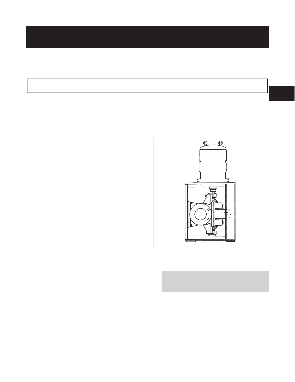
Vertical Application. Goulds Model 3410 is available in a
vertical configuration (3410V) (Fig. 1). This arrangement is
ideal for applications with limited space such as shipboard
service. A rugged fabricated steel frame supports the pump
and driver, providing a machined fit for positive alignment
when using standard P-base motors.
Fig 1
DESCRIPTION
Features. Pump sizes with an H designation are designed
for a higher flow than the equivalent size standard pump.
External casing dimensions are the same, but the H pumps
have wider casing cutwaters and impellers.
The complete model line has four different shafts with only
two bearing assemblies. Standard constructions are all iron,
bronze fitted, 316SS fitted, and all 316SS, with other
constructions available upon request.
Right hand rotation is standard with left hand available as
an option. The rotation can be changed in the field without
any additional parts.
3410 IOM 1/2010 11
Leakage of process liquid may result in creating an
!
explosive atmosphere. Ensure the materials of the
pump casing, impeller, shaft, sleeves, gaskets and
seals are compatible with the process liquid.
Casing - The casing is horizontally split. The upper and
lower halves are held together with capscrews plus studs on
each side of each stuffing box to aid in disassembly/
reassembly. Flanged suction and discharge connections are
located in the lower half of the casing and conform to
ANSI 16.1/16.5 class 125/150. The casing is supported by
integrally cast feet. Separate bearing housings are attached
directly to machined fits in each end of the casing with
capscrews. Fourteen of the 27 casings are double volute as
tabulated on the next page.
Page 14

DOUBLE VOLUTE CASINGS
4x6-11 8x10-21
impeller and held axially in place using threaded sleeve
nuts. The S group pumps are standard without shaft
sleeves, but sleeves are available.
4x6-11H 10x12-12
6x8-11 10x12-12H*
8x10-12 10x12-14
8x10-14 10x12-17
8x10-17 10x12-15
8x10-17H 12x14-14
12x14-15
*Casing uses a partial splitter.
125# flat face flanges are standard with 250# flat face
available as an option. The casings are standard with two
jack screws (except S group), two lifting lugs, two tapered
dowel pins for alignment, and a 0.030 inch (.0762 cm)
parting gasket.
The upper half casing is provided with a vent connection, a
priming connection, and two stuffing box seal ring
connections. The lower half is provided with two drain
connections.
Stuffing Box - Non-asbestos stuffing box packing is
standard. The stuffing box contains split lantern rings and
renewable stuffing box throat bushings. Tapped openings
are provided for water sealing from either the pump casing
or an outside source. Bypass piping is optional. Two-piece
investment cast 316SS non-quench glands are standard on
all 3410 pumps.
Mechanical Seals - Mechanical seals are available as an
option on the Model 3410. Oversize stuffing box bores are
standard on pumps provided with factory installed
mechanical seals, providing greater flexibility and an
improved operating environment.
Pumps which are originally supplied with standard packed
boxes can be converted to mechanical seals in the field.
This conversion requires either a remachine of the stuffing
boxes or a gland remachine to adapt to the existing stuffing
boxes. Remachining of the stuffing box bores allows use of
all standard Model 3410 mechanical seals and the standard
I.D. pilot glands. Conversion to stepped sleeves would be
required for balanced seals. Most unbalanced mechanical
seals will fit in the standard packed box bores, but this
requires remachining the I.D. pilot off the glands. In this
case, the glands must be centered on the shaft or sleeve
utilizing a feeler gauge.
Impeller - The impeller is an enclosed, double suction
design providing axial hydraulic balance. The impeller is
dynamically balanced as standard when the diameter to
width ratio is less than six. The impeller is key driven.
Wear Rings - Casing wear rings are supplied as standard to
maintain proper running clearance and to minimize leakage
between the suction and discharge chambers in the casing.
Each casing ring is held in place by a single anti-rotation
pin, located in a milled slot at the horizontal parting
surface. Optional impeller wear rings are available on all
pump sizes. The impeller wear rings are held in position by
axial set screws. Field installation of impeller rings requires
a remachining of the impeller hubs. The casing rings
remain the same for both the less-impeller ring and
with-impeller ring designs.
Shaft - The shaft is a heavy duty design that minimizes
deflection and vibration. The shaft deflection is a maximum
of .002 in (.005 mm) at the stuffing box face under the
worst operating conditions. The shaft on the M, L and XL
group pump is completely dry with gasket seals between
the impeller hubs and shaft sleeves. The S group does not
have a completely dry shaft. The S group is standard with a
420 stainless steel shaft. The M, L, and XL sizes have an
ANSI 4140 steel shaft standard, with an option for 316
stainless steel.
Shaft Sleeves -T he M, L and XL group pumps have
standard Shaft Sleeves. They are keyed to the shaft at the
Pumps supplied with mechanical seals can also be
converted to packed boxes in the field. A cartridge
conversion kit is available and includes a box of fittings,
plus sleeves to convert to oversize bores to standard packed
box bores.
Bearings - The Model 3410 is standard with double row
ball thrust bearings and a single row deep groove ball
bearing at the coupling end. There are only two sizes of
bearing housings and bearings utilized on the complete
Model 3410 product line. The S and M groups utilize
identical bearings, as do the L and XL groups. The thrust
bearing is held in position with a tapered snap ring and is
locked in the thrust bearing housing to take any unbalanced
axial thrust load. The radial bearing is free to float axially
in the bearing housing taking radial loads only.
Grease lubrication is standard. Oil lubrication is optional
and utilizes the same shaft, bearings, and bearing housings.
Bearing cooling is available with oil lubrication only, and
is required for temperatures over 250 degrees F (121
degrees C). The bearing housings are completely sealed by
Inpro VBS bearing isolators.
Bedplates - Cast iron bedplates are furnished as standard.
They include a drip collection chamber with a tapped drain
connection and an opening suitable for grouting. Fabricated
steel bedplates are available as an option.
12 3410 IOM 1/2010
Page 15
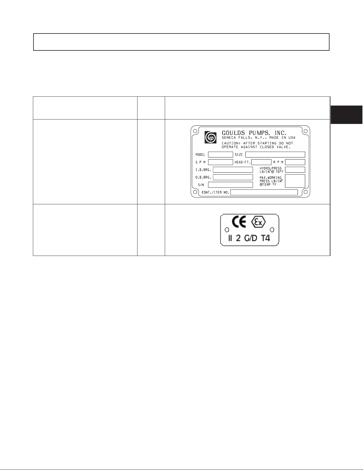
NAMEPLATE INFORMATION
Every pump has a Goulds nameplate that provides
information about the pump. The tags are located on
the pump casing.
Description Fig. No. Example
Pump Casing Tag - provides information
about the pump’s hydraulic
characteristics. Note the format of the
pump size: Discharge x Suction - Nominal
maximum Impeller Diameter in inches.
(Example: 2x3-11) (Fig. 2).
ATEX Tag - If applicable, your pump
unit may have the following ATEX tag
affixed to the pump and/or baseplate. See
the Safety section for a description of the
symbols and codes (Fig. 3).
Fig. 2
Fig. 3
When ordering parts, you will need to identify the pump model,
size, serial number, and the item number of the required parts.
Information can be taken from the pump casing tags. Item
numbers can be found later on in this manual.
2
3410 IOM 1/2010 13
Page 16

14 3410 IOM 1/2010
Page 17

INSTALLATION
RECEIVING THE PUMP .............................15
Storage Requirements .............................15
Lifting the Pump ................................16
Horizontal ...................................16
Vertical .....................................17
STORAGE......................................17
Temporary ...................................17
Long Term ...................................17
LOCATION .....................................18
FOUNDATION ...................................18
SETTING THE BASEPLATE ...........................18
Grouting Procedure...............................19
ALIGNMENT ....................................20
Alignment Checks ...............................20
DOWELING.....................................22
SUCTION AND DISCHARGE PIPING .....................22
Suction Piping .................................22
Discharge Piping ................................24
Pressure Gauges ................................24
3
Equipment that will operate in a potentially explosive environment must be installed in accordance with the
!
following instructions.
RECEIVING THE PUMP
Check pump for shortages and damage immediately upon
arrival (an absolute must!). Prompt reporting to the
carrier’s agent, with notations made on the freight bill, will
expedite satisfactory adjustment by the carrier.
Pumps and drivers are normally shipped from the factory
mounted on a baseplate. Couplings may either be
completely assembled or have the coupling hubs mounted
on the shafts and the connecting members removed. When
the connecting members are removed, they will be
packaged in a separate container and shipped with the
pump or attached to the baseplate.
STORAGE REQUIREMENTS
Short Term: (Less than 6 months): Goulds normal
packaging procedure is designed to protect the pump
during shipping. Upon receipt, store in a covered and dry
location.
Long Term: (More than 6 months): Preservative treatment
of bearings and machined surfaces will be required. Rotate
shaft several times every three months. Refer to driver and
coupling manufacturers for their long term storage
procedures. Store in a covered dry location.
NOTE: Long term storage treatment can be purchased
with the initial pump order.
3410 IOM 1/2010 15
Page 18

LIFTING THE PUMP
Bases supplied with lifting holes
! WARNING
s
Pump and components are heavy. Failure to properly
lift and support the equipment could result in serious
physical injury, or damage to the pump(s). Steel-toed
shoes must be worn at all times.
The following instructions are for the safe lifting of your
pump.
The unit should be unloaded and handled by lifting equally
at four or more points on the baseplate. The lugs on the
upper half casing are designed for lifting the upper half
casing only.
HORIZONTAL
Bare Pump
1. Using a nylon sling, chain, or wire rope, hitch around
both bearing housings. (See Fig. 4)
Large bases are supplied with lifting holes in the sides or
the ends of the base. (See Fig. 5)
Fig. 5
Using ANSI/OSHA Standard “S” hooks, place the “S” hooks in
the holes provided in the four corners of the base. Be sure the
points of the hooks do not touch the bottom of the pump base.
Attach nylon slings, chains, or wire rope to the “S” hooks. Size
the equipment for the load so the lift angle will be less than 45°
from the vertical.
Bases supplied without lifting holes
Fig. 4
Pump, Base, and Driver
2. Care must be taken to size equipment for unbalanced
loads which may exist if the driver is not mounted on
the base at the time of lifting. Driver may or may not
be mounted at the factory.
3. Pump, base, and driver assemblies where the base
length exceeds 100 inches may not be safe to lift as a
complete assembly. Damage to the baseplate may
occur. If the driver has been mounted on the baseplate
at the factory, it is safe to lift the entire assembly. If
driver has not been mounted at the factory and the
overall baseplate length exceeds 100 inches, do not lift
entire assembly consisting of pump, base, and driver.
Instead, lift the pump and baseplate to its final
location without the driver. Then mount the driver.
Place one sling around the outboard bearing housing.
! WARNING
s
Do not use lugs on top half of casing.
Place the remaining sling around the back end of the driver as
close to the mounting feet as possible. Make certain sling will not
damage housing cover or conduit boxes.
Join the free ends of the slings together and place over the lifting
hook. Use extreme care when positioning sling under the driver
and bearing housing so it cannot slip off (See Fig. 6).
Fig. 6
16 3410 IOM 1/2010
Page 19

VERTICAL
Half Pedestal
1. Place nylon sling chain or wire rope around both
flanges. Use a latch hook or standard shackle and end
loops.
Be sure the lifting equipment is of sufficient length to
keep the lift angle less than 30° from the vertical. (See
Fig. 7)
Fig. 7
Full Pedestal
2. Install eyebolts in the three holes provided at the top of the
support, being sure to tighten securely. Attach chain or wire
rope using latch hook or standard shackle and end loop.
Be sure to use shoulder eyebolts that are manufactured per
ANSI B18.15 and sized to fit the holes provided.
Be sure lifting equipment is of sufficient length to
keep the lift angle less than 30° from the vertical.
(See Fig. 8)
3
STORAGE
The following storage procedures apply to the pump only.
Other accessories such as motors, steam turbines, gears,
etc., must be handled per the respective manufacturer’s
recommendations.
TEMPORARY
Temporary storage is considered one month or less.
If the pump is not to be installed and operated soon after
arrival, store it in a clean, dry place having slow, moderate
changes in ambient temperature. Rotate the shaft
periodically to coat the bearings with lubricant and to
retard oxidation, corrosion, and to reduce the possibility of
false brinelling of the bearings. Shaft extensions and other
exposed machine surfaces should be coated with an easily
removable rust preventative such as Ashland Oil Tectyl
No. 502C.
Fig. 8
For oil lubricated bearings, fill the frame completely with
oil. Before putting equipment into operation, drain the oil
and refill to proper level.
LONG TERM
Storage longer than one month is considered long term
storage. Follow the same procedure for temporary storage
with the following addition. Add one half ounce of a
corrosion inhibiting concentrated oil such as Cortec Corp.
VCI-329 (for both grease and oil lubricated bearings). Seal
all vents and apply a water proof tape around the oil seals
in the bearing frame. Remember for oil lubricated bearings
to drain the oil from the frame and refill to the proper level
before running pump.
3410 IOM 1/2010 17
Page 20

LOCATION
All equipment being installed must be properly
!
grounded to prevent unexpected static electric
discharge.
The pump should be installed as near the suction supply as
possible, with the shortest and most direct suction pipe
practical. The total dynamic suction lift (static lift plus
friction losses in suction line) should not exceed the limits
for which the pump was sold.
The pump must be primed before starting. Whenever
possible, the pump should be located below the fluid level
to facilitate priming and assure a steady flow of liquid. This
condition provides a positive suction head on the pump. It
is also possible to prime the pump by pressurizing the
suction vessel.
When installing the pump, consider its location in relation
to the system to assure that sufficient Net Positive Suction
Head (NPSHA) is available at the pump inlet connection.
Available NPSH must always equal or exceed the required
NPSH (NPSHR) of the pump.
FOUNDATION
The pump should be installed with sufficient accessibility for
inspection and maintenance. A clear space with ample head
room should be allowed for the use of an overhead crane or
hoist sufficiently strong to lift the unit.
NOTE: Allow sufficient space to be able to dismantle
pump without disturbing the pump inlet and discharge
piping.
Select a dry place above the floor level wherever possible. Take
care to prevent pump from freezing during cold weather when
not in operation. Should the possibility of freezing exist during a
shut-down period, the pump should be completely drained, and
all passages and pockets where liquid might collect should be
blown out with compressed air.
Make sure there is a suitable power source available for the
pump driver. If motor driven, the electrical characteristics of the
power source should be identical to those shown on motor data
plate.
The foundation must be substantial enough to absorb
vibration. (Hydraulic Institute Standards recommends the
foundation weigh at least five (5) times the weight of the pump
unit.) It must form a permanent and rigid support for the
baseplate. This is important in maintaining the alignment of a
flexibly coupled unit.
Foundation bolts of the proper size should be embedded in the
concrete to a depth of eight (8) to twelve (12) inches and
locked with either a hook around a reinforcing bar or
alternatively, a nut and washer at the bottom. The bolts should
have a sleeve around them at least six (6) times the bolt
diameter in length and at least two (2) bolt sizes larger in I.D.
If a nut and washer are used for locking, the washer should
have an O.D. two (2) sizes larger than the sleeve. Foundation
bolts should be sized .125" less than the anchor bolt holes in
the base.
SETTING THE BASEPLATE
Pump units are checked at the factory for align ability to
required tolerances.
Due to flexibility of an ungrouted base and handling in
shipment, it should not be assumed that the unit is in
alignment when it is placed on the rough foundation.
If these directions are followed, the required alignment should
be readily achieved.
The foundation should be poured to within .75" - 1.5" of
the finished height. (See Fig. 9) Freshly poured foundations
should be allowed to cure for several days before the unit is
set in place and grouted.
Fig. 9
Initial or rough alignment must be done prior to grouting of
baseplate. Rough alignment is designated as .020" TIR (Total
Indicator Reading) parallel alignment and .009" TIR per inch of
radius angular alignment (See ALIGNMENT PROCEDURE).
Use blocks at anchor bolts and midway between to position
bottom of base at finished height (See Fig. 10) with foundation
bolts extending through holes in the baseplate. Metal wedges
with a small taper may be used in lieu of blocks and shims.
18 3410 IOM 1/2010
Page 21

Fig. 10
If the unit has a non-flexible coupling (e.g. Falk Gear
coupling), the coupling halves should be disconnected; this
is generally not necessary on flexible type couplings (e.g.
Wood’s Sure-Flex coupling).
Tighten up all pump and motor bolts to assure they have not
loosened or a “soft foot” has occurred due to base distortion in
shipment. A “soft foot” causes a change in the alignment when
unloosening one bolt.
NOTE: The baseplate does not have to be level.
After foundation bolts are lightly torqued, recheck
alignment requirements once more. Follow requirements
outlined at the beginning of this section. If alignment must
be corrected, add or remove shims or wedges under the
baseplate.
The unit can then be grouted. (See Fig. 10)
Grout compensates for the uneven foundation. Together
with the baseplate, it makes a very rigid interface between
the pump and the foundation distributing the weight over
the length of the base and preventing shifting.
Use an approved, non-shrinking grout such as Embeco 636
or 885 by Master Builders, Cleveland, Ohio or equivalent.
$
Do not grout until initial alignment is made.
CAUTION
GROUTING PROCEDURE
1. Build a strong form around the foundation to contain
the grout.
2. Soak the top of the foundation thoroughly, then
remove surface water.
3
If the driver is being field installed, it should be centered in its
bolt holes with shims added to bring the driver into rough
alignment with the pump. (The pump may have to be moved
also.)
$
Do not exceed six (6) shims, using as thick a shim as
possible, otherwise “sponginess” or “soft foot” will result.
Place thin shims in between thick shims.
Level and plumb the pump shaft, coupling faces and flanges by
adding or removing shims between the blocks and the bottom of
the base. Hand tighten the anchor bolt nuts at first. Being very
careful not to distort the base, snug down the nuts with a
wrench. The non-flexible coupling should not be reconnected
until the alignment operation has been completed.
!CAUTION
3. The baseplate should be completely filled with grout
and, if necessary, temporarily use air relief tubing or
drill vent holes to remove trapped air.
4. After the grout has thoroughly hardened
(approximately 24 hours), tighten the foundation bolts
fully.
5. Check the alignment after the foundation bolts are
tightened.
6. Approximately fourteen (14) days after the grout has
been poured and the grout has thoroughly dried, apply an
oil base paint to the exposed edges of the grout to prevent
air and moisture from coming in contact with the grout.
3410 IOM 1/2010 19
Page 22

ALIGNMENT
Alignment procedures must be followed to prevent
!
unintended contact of rotating parts. Follow
coupling manufacturer’s installation and operation
procedures.
B
Before beginning any alignment procedure, make sure
driver power is locked out. Failure to lock out driver
power may result in serious physical injury.
Alignment is achieved by adding or removing shims from
under the feet of the driver and shifting equipment
horizontally as needed.
NOTE: Proper alignment is the responsibility of the
installer and user of the unit.
Accurate alignment of the equipment must be attained.
ALIGNMENT CHECKS
Initial Alignment (Cold Alignment)
•
•
•
Final Alignment (Hot Alignment)
! WARNING
s
A
Before Grouting Baseplate - To ensure alignment can
be obtained.
After Grouting Baseplate - To ensure no changes have
occurred during grouting process.
After Connecting Piping - To ensure pipe strains have
not altered alignment. If changes have occurred, alter
piping to remove pipe strains on pump flanges.
NOTE: During installation phase, however, it is
necessary to set the parallel alignment in the vertical
direction to a different critera due to the differences in
expansion rates of the pump and driver. Table 2 shows
recommended preliminary (cold) settings for electric
motor driven pumps based on different pumpage
temperatures. Driver manufacturers should be
consulted for recommended cold settings of other types
of drivers (steam turbines, engines, etc.)
Pumpage
Temperature
Above
Ambient
Set Motor Shaft
Temperature
Ambient 0.002" (0.005mm) - .004" (0.010mm) Low
100° F (38° C) 0.000" (0.0mm) - .002" (0.005mm) High
200° F (93°C) 0.004" (0.010mm) - .006" (0.15mm) High
300° F (149°C) 0.008" (0.020mm) - .010" (0.25mm) High
400° F (204°C) 0.012" (0.030mm) - .014" (0.35mm) High
The necessary tools for checking alignment are: (1) a straight
edge and a taper gauge or set of feeler gauges or, (2) a dial
indicator with mounting magnet and extension bars.
Check and correct for angular misalignment before correcting
parallel alignment. Final alignment should be made by moving
and shimming the motor on its base until the coupling hubs are
within the recommended tolerances measured in total run out.
All measurements should be taken with the pump and driver
bolts tightened. Final alignment check should be made after the
unit has attained its final operating temperature.
After First Run - To obtain correct alignment when
•
both pump and driver are at operating temperature.
Thereafter, alignment should be checked periodically
in accordance with plant operating procedures.
NOTE: Alignment check must be made if process
temperature changes, piping changes and or pump
service is performed.
Proper rough alignment must be made during unit setting
and grouting. See previous section.
There are two forms of misalignment between the pump
shaft and the driver shaft as follows:
1. Angular misalignment — shafts have axis concentric
at intersection, but not parallel.
2. Parallel offset misalignment — shafts have axis
parallel, but offset.
Method 1 - Using straight edge and taper gauges or feelers
(Fig. 11):
Proceed with this method only if satisfied that face and
outside diameters of the coupling halves are square and
concentric with the coupling bores. If this condition does
not exist or elastomeric couplings do not make this method
convenient, use Method 2.
Check for angular alignment by inserting the taper or feeler
gauges between the coupling faces at 90° intervals. The
unit is in angular alignment when these four (4)
measurements are the same, or within recommended
tolerances.
Check for parallel alignment by placing a straight edge
across both coupling rims on all four sides. The unit is in
parallel alignment when the straight edge rests evenly
across both coupling rims in all four (4) positions.
20 3410 IOM 1/2010
Page 23

Fig. 10
3
Fig. 11
Method 2 - Dial Indicators (Fig. 12):
A dial indicator can be used to attain more accurate
alignment.
Fasten the indicator stand or magnetic base to the pump
half of the coupling and adjust the assembly until the
indicator button is resting on the other half coupling
periphery.
Set the dial to zero and chalk mark the coupling half where
the button rests. Also place a separator between the
coupling halves so bearing slack does not affect the
readings. (Chalk and separators are not necessary on the
elastomeric couplings that have not been disconnected.)
Rotate both shafts by the same amount; i.e., all readings
must be made with the button on the chalk mark.
The dial readings will indicate whether the driver has to be
raised, lowered or moved to either side. Accurate alignment
of shaft centers can be obtained with this method even
where faces or outside diameters of the coupling are not
square or concentric with the bores. After each adjustment,
recheck both parallel and angular alignments.
NOTE: Gross deviations in squareness or
concentricity may cause rotation unbalance problems
and if so must be corrected.
PERMISSIBLE COUPLING
MISALIGNMENT
Double Element
(spacer) Coupling
.060” TIR
per foot of spacer length
.002” TIR
per inch of radius
Parallel
Angular
Single Element
Coupling
.004” TIR
(4 mils)
.004” TIR
per inch of radius.
Fig. 12
3410 IOM 1/2010 21
Page 24

DOWELING
Pump units may, if desired, (or required in specification) be
doweled on diagonally opposite feet. This should not be
SUCTION AND DISCHARGE PIPING
Flange loads from the piping system, including
!
those from thermal expansion of the piping, must
not exceed the limits of the pump. Casing
deformation can result in contact with rotating parts
which can result in excess heat generation, sparks
and premature failure.
The introduction of pumpage into a piping system which is not
well designed or adjusted may cause strain on the pump, leading
to misalignment or even impeller rubbing. Since slight strain may
go unnoticed, final alignment should be done with the system full
and up to final temperature.
Pipe flanges should not impose any strain on the pump. This can
be checked by a dial indicator. Any strain must be corrected by
adjustments in the piping system.
When installing the pump piping, be sure to observe the following
precautions:
Piping should always be run to the pump.
Do not move the pump to pipe. This could make final alignment
impossible.
Both the suction and discharge piping should be independently
anchored near the pump and properly aligned so that no strain is
transmitted to the pump when the flange bolts are tightened. Use
pipe hangers or other supports at necessary intervals to provide
support. When expansion joints are used in the piping system they
must be installed beyond the piping supports closest to the pump.
Tie bolts and spacer sleeves should be used with expansion joints
to prevent pipe strain. Do not install expansion joints next to the
pump or in any way that would cause a strain on the pump
resulting from system pressure changes. When using rubber
expansion joints, follow the recommendations of the Technical
Handbook on Rubber Expansion Joints and Flexible Pipe
Connectors. It is usually advisable to increase the size of both
suction and discharge pipes at the pump connections to decrease
the loss of head from friction.
Install piping as straight as possible, avoiding unnecessary bends.
Where necessary, use 45° or long radius 90° fittings to decrease
friction losses.
Make sure that all piping joints are air-tight.
Where flanged joints are used, assure that inside diameters match
properly.
Remove burrs and sharp edges when making up joints.
done until the unit has been run for a sufficient length of
time and alignment is within the above alignment tolerance.
Do not “spring” piping when making any connections.
Provide for pipe expansion when hot fluids are to be pumped.
Fig. 13
SUCTION PIPING
When installing the suction piping, observe the following
precautions. (See Fig. 14)
The sizing and installation of the suction piping is extremely
important. It must be selected and installed so that pressure
losses are minimized and sufficient liquid will flow into the
pump when started and operated.
Many NPSH (Net Positive Suction Head) problems can be
directly attributed to improper suction piping systems.
Suction piping should be short in length, as direct as
possible, and never smaller in diameter than the pump
suction opening. A minimum of five (5) pipe diameters
between any elbow or tee and the pump should be allowed.
If a long suction pipe is required, it should be one or two
sizes larger than the suction opening, depending on its
length.
$
An elbow should not be used directly before the suction of
a double suction pump if its plane is parallel to the pump
shaft. This can cause an excessive axial load or NPSH
problems in the pump due to an uneven flow distribution
(See Fig. 13). If there is no other choice, the elbow should
have straightening vanes to help evenly distribute the flow.
Eccentric reducers should be limited to one pipe size
reduction each to avoid excessive turbulence and noise.
They should be of the conical type. Contour reducers are
not recommended.
CAUTION
22 3410 IOM 1/2010
Page 25

When operating on a suction lift, the suction pipe should
slope upward to the pump nozzle. A horizontal suction line
must have a gradual rise to the pump. Any high point in the
pipe can become filled with air and prevent proper
operation of the pump. When reducing the piping to the
suction opening diameter, use an eccentric reducer with the
eccentric side down to avoid air pockets.
NOTE: When operating on suction lift neveruse a
concentric reducer in a horizontal suction line, as it
tends to form an air pocket in the top of the reducer
and the pipe.
Fig. 14 shows some correct and incorrect suction piping
arrangements.
When installing valves in the suction piping, observe the
following precautions:
1. If the pump is operating under static suction lift
conditions, a foot valve may be installed in the suction
line to avoid the necessity of priming each time the
pump is started. This valve should be of the flapper
type, rather than the multiple spring type, sized to
avoid excessive friction in the suction line. (Under all
other conditions, a check valve, if used, should be
installed in the discharge line. See Discharge Piping.)
2. When foot valves are used, or where there are other
possibilities of “water hammer,” close the discharge
valve slowly before shutting down the pump.
3. Where two or more pumps are connected to the same
suction line, install gate valves so that any pump can
be isolated from the line. Gate valves should be
installed on the suction side of all pumps with a
positive pressure for maintenance purposes. Install
gate valves with stems horizontal to avoid air pockets.
Globe valves should not be used, particularly where
NPSH is critical.
$
The pump must never be throttled by the use of a valve
on the suction side of the pump. Suction valves should
be used only to isolate the pump for mainten- ance
purposes, and should always be installed in positions to
avoid air pockets.
CAUTION
3
3410 IOM 1/2010 23
Page 26

DISCHARGE PIPING
If the discharge piping is short, the pipe diameter can be the
same as the discharge opening. If the piping is long, the
pipe diameter should be one or two sizes larger than the
discharge opening. On long horizontal runs, it is desirable
to maintain as even a grade as possible. Avoid high spots,
such as loops, which will collect air and throttle the system
or lead to erratic pumping.
A check valve and an isolating gate valve should be
installed in the discharge line. The check valve, placed
between pump and gate valve, protects the pump from
excessive back pressure, and prevents liquid from running
back through the pump in case of power failure. The gate
valve is used in priming and starting, and when shutting the
pump down.
PRESSURE GAUGES
Properly sized pressure gauges should be installed in both
the suction and discharge nozzles in the gauge taps
provided. The gauges will enable the operator to easily
observe the operation of the pump, and also determine if
the pump is operating in conformance with the performance
curve. If cavitation, vapor binding, or other unstable
operation should occur, widely fluctuating discharge
pressure will be noted.
Fig. 14
24 3410 IOM 1/2010
Page 27

OPERATION
PREPARATION FOR STARTUP ..........................25
Checking Rotation ..................................25
Couple Pump and Driver ..............................25
Lubricating Bearings ................................26
Shaft Sealing Packing ................................27
Connection of Sealing Liquid (Packed Box) ....................29
Mechanical Seal Flushing/Cooling Piping .....................30
Connection of Drain Piping .............................30
Priming the Pump ..................................30
STARTING THE PUMP ...............................33
OPERATION ......................................33
SHUTDOWN ......................................34
FINAL ALIGNMENT .................................34
PREPARATION FOR STARTUP
Service temperature in an ATEX classified
!
environment is limited to the area classification
specified on the ATEX tag affixed to the pump
(reference Table 1 in the Safety section for ATEX
classifications).
4
2. Make sure coupling hubs are securely fastened to the
shafts and the coupling spacer has been removed.
NOTE: Pump is shipped with coupling spacer
removed.
3. Unlock driver power.
Ensure that pump and systems are free of foreign
!
objects before operating and that objects cannot
enter the pump during operation. Foreign objects in
the pumpage or piping system can cause blockage of
flow which can result in excess heat generation,
sparks and premature failure.
Cooling systems such as those for bearing
!
lubrication, mechanical seal systems, etc, where
provided, must be operating properly to prevent
excess heat generation, sparks, and premature
failure.
When installing in a potentially explosive
!
environment, ensure that the motor is properly
certified.
CHECKING ROTATION
$
A
Serious damage may result if pump is run in the wrong
rotation.
1. Lock out power to driver.
! WARNING
s
Lock out driver power to prevent accidental start-up
and physical injury.
CAUTION
4. Make sure everyone is clear. Jog driver just long enough
to determine direction of rotation. Rotation must
correspond to arrow on bearing housing.
5. Lock out power to driver.
COUPLE PUMP AND DRIVER
! WARNING
B
s
Lock out driver power to prevent accidental rotation
and physical injury.
The coupling used in an ATEX classified
!
environment must be properly certified.
1. Install and lubricate coupling per manufacturer’s
instructions.
2. Install coupling guard.
The coupling guard used in an ATEX classified
!
environment must be constructed from a
non-sparking material.
! WARNING
s
Never operate a pump without coupling guard properly
installed. Personal injury will occur if pump is run
without coupling guard.
3410 IOM 1/2010 25
Page 28

LUBRICATING BEARINGS
Bearings must be lubricated properly in order to
!
prevent excess heat generation, sparks and
premature failure.
They are included in box of fittings which accompanies the
pump. Oil adjustments must be set prior to lubrication. See
Preventive Maintenance for recommended lubricants and
supplies.
For Initial Oil Lubrication of New Bearings
Do not insulate bearing housings as this can result
!
in excess heat generation, sparks and premature
failure.
Grease Lubrication (Standard). Grease lubricated pumps
can be identified by grease fittings located on bearing
housing. Sufficient lubricant is inserted at factory for 2,000
hours of operation. See Preventive Maintenance for grease
lubrication instructions.
Oil Lubrication (Optional). Oil lubricated pumps are not
lubricated at factory. A high quality turbine type oil, with
rust and oxidation inhibitors, should be used. Constant
level oilers are supplied with most oil lubricated pumps.
1. Remove oiler (1), Fig. 15.
2. Remove adjustment assembly (2) from oiler.
3. Adjust bars to dimension A, as required, Table 3.
4. Lock in position.
5. Replace adjustment assembly in oiler.
6. Install oiler.
$
A
Bar adjust must be adjusted as stated in procedure c(3).
If not adjusted properly, bearing will not be lubricated.
NOTE: Never fill through oil vent or oiler housing.
CAUTION
TABLE 3
GROUP
S&M
L&XL
AB
in.
(mm)
9/16
(14.5mm)
9/16
(14.5mm)
in.
(mm)
1/2
(13mm)
1/2
(13mm)
OILER
SIZE
ounces
(ml)
#5 8oz
(204ml)
#5 8oz
(204ml)
CASING
CAPACITY
ounces
(ml)
9oz
(266ml)
16 1/2oz
(489ml)
Fig. 15
7. Fill each bottle with oil and replace in oiler
housing.Oil reservoir in bearing housing is filled
when oil remains visible in bottle. Several fillings of
bottle are required.
Bearing cooling is available with oil lubrication (optional)
only. When used, cooling water must be connected to
bearing housing, and a waste or return line must be used.
Water cooling is required when operating temperatures
exceed 250° F (121°C).
DRIVER BEARINGS
Check to be sure that driver bearings are properly
lubricated. Contact motor manufacturer for lubrication
instructions.
26 3410 IOM 1/2010
Page 29

SHAFT SEALING PACKING
Packing
Packed stuffing boxes are not allowed in an ATEX
!
classified environment.
1. Before packing stuffing box, make sure box is clean
and contains no foreign material.
2. Install gland studs into the casing if not already
installed.
3. Stuffing box packing furnished in box of fittings
which accompanies pump. When packing stuffing box
arrangement of packing and lantern rings is: two
packing rings, lantern ring; then last three packing
rings, as shown in Fig. 16.
Fig. 18
6. To pack stuffing box, install packing and lantern ring
in proper sequence. Each ring should be installed
separately. Firmly seat each ring. Use stuffing box
gland to push packing and lantern ring into box,
Fig. 19. Stagger joints in each ring 90 degrees. Make
sure center of lantern ring lines up with flush tap in
stuffing box. Any extra rings are spares.
4
Fig. 16
4. Twist packing ring sideways just enough to get it
around shaft or sleeve (Fig. 17).
Fig. 17
5. Two-piece Teflon lantern rings are supplied in all
3410s. Twist lantern ring halves just enough to get it
around shaft sleeve as shown in Fig. 18.
NOTE: Two pieces make one ring. Notches must face
one another but need not be aligned.
Fig. 19
7. Hand-tighten gland nuts evenly but not tight.
Removal of Packing
To remove packing from stuffing box, proceed as follows:
1. Remove gland assembly.
2. Remove packing with a packing hook.
3. Remove lantern ring by inserting a wire hook into
ring on outer edge.
4. Clean stuffing box.
An alternate method of removing packing is to remove
upper half casing (see Disassembly & Reassembly section.)
Remove packing and lantern ring and inspect sleeves
and/or shaft. Replace sleeves or shaft if deeply grooved.
3410 IOM 1/2010 27
Page 30

Mechanical Seals
The mechanical seal used in an ATEX classified
!
environment must be properly certified.
When mechanical seals are furnished, description and
identification is indicated on order write-ups. Separate seal
manufacturer’s installation drawings are attached to pump.
Most seals are installed and adjusted at the factory.
Manufacturer’s drawings should be filed for future use in
maintaining seal and in adjusting seal when pump is
disassembled. To properly prepare seal for operation,
various cooling and flushing flows may have to be
connected. In some cases, these flows are recirculated from
pump casing; in others, liquid from an outside source may
be used. Connect cooling and flushing flows to seal as
directed in manufacturer’s instructions.
All Model 3410 mechanical seals utilize o-ring
•
mounted stationary seats and a flush gland with a pilot
fit in the I.D. of the stuffing box as standard. All S
group pumps are standard less shaft sleeves, with
sleeves available as an option. M, L, and XL groups
are standard with shaft sleeves and sleeve nuts.
A single inside unbalanced or integrally balanced
(metal bellows) seal for an S group pump is illustrated
in Fig. 20. This design incorporates the standard
420SS sleeveless shaft and oversized stuffing box
bore. The stuffing box bore is used to pilot the
standard gland.
Conventional balanced seals require the use of a
•
stepped shaft sleeve. Figure 22 shows an S group
pump with a stub sleeve to accomplish the seal
balancing. A standard stepped sleeve is used on the M
group to reduce the mounting diameter down to the
standard sleeve nut O.D.. This is illustrated in Fig. 23.
Bellows type mechanical seals are integrally balanced
and do not require a step in the sleeve. They can be
mounted directly on the sleeveless S group shaft of on
the standard non-balanced M group sleeve (Fig. 21.)
Fig. 22
Figure 21 illustrates the same type of seal as sown in
•
Fig. 20, but for M group pumps. Note the shaft is
protected by sleeves and sleeve nuts as standard. All
other features and details are the same.
Fig. 20
Fig. 21
Pumps which are originally supplied with packing
•
boxes can be converted to mechanical seals in the
field. This conversion requires a remachine of the
stuffing box to allow for the standard gland pilot
feature (Figures 20 and 21) or a remachine operation
of the standard gland to remove the pilot lip (Figures
24 and 25.) In this case, a shimming operation is
required to center the gland on the shaft.
Fig. 23
Fig. 24
28 3410 IOM 1/2010
Page 31

Fig. 25
Figure 24 shows a single inside unbalanced
•
mechanical seal mounted in the S group standard
stuffing box. You will note that the pilot lip has been
machined off the gland since there is inadequate room
in the bore for the pilot. With this arrangement, it is
necessary to use a feeler gauge or shims to center the
gland on the shaft.
Figure 25 shows a bellows type balanced mechanical
•
seal mounted in an S group standard stuffing box.
There is inadequate room in the standard stuffing box
to mount a conventional balanced seal requiring a
stepped shaft sleeve. Use of these seals requires a
remachine of the stuffing box bores.
CONNECTION OF SEALING LIQUID
(PACKED BOX)
General
If stuffing box pressure is above atmospheric pressure and
pumpage is clean, normal gland leakage of 40 to 60 drops
per minute is usually sufficient to lubricate and cool
packing and sealing liquid is not required.
Clean sealing liquid is required when:
Abrasive particles in pumpage could score shaft of
•
sleeve.
Stuffing box pressure is below atmospheric pressure
•
due to pump running with suction lift, or when
suction source is under vacuum. Under these
conditions, packing will not be cooled and lubricated
and air will be drawn into pump.
Sealing Liquid
Sealing liquid may be supplied by recirculation of pumpage
through a line from casing to stuffing box. If pumpage is
abrasive, an outside source of clean compatible liquid must
be used at a pressure of 15 PSI or greater above suction
pressure.
4
The following mechanical seals can be installed in
standard stuffing boxes by utilizing a remachined,
non-pilot gland:
- Crane type 1, 81T, 9T, and Metal Bellows (680)
- Flowserve RO
Pumps supplied with mechanical seals can be
•
converted to packing. A packing conversion kit is
available as shown in Fig. 26. It includes all the
standard stuffing box fittings plus a liner sleeve that
presses into the oversize stuffing box bore.
CONNECTION OF COOLING
WATER PIPING TO OPTIONAL
PUMP FEATURES
Quench Gland
Tapped openings on top of the quench gland are provided
for water sealing. Bypass piping is connected from a “T”
installed in vent plug opening at top of upper casing to the
tapped opening in the stuffing box.
Fig. 26
3410 IOM 1/2010 29
Page 32

MECHANICAL SEAL FLUSHING/
COOLING PIPING
The mechanical seal must have an appropriate seal
!
flush system. Failure to do so will result in excess
heat generation and seal failure.
Sealing systems that are not self purging or self
!
venting, such as plan 23, require manual venting
prior to operation. Failure to do so will result in
excess heat generation and seal failure.
PRIMING THE PUMP
Pumps must be fully primed at all times during
!
operation.
A build up of gases within the pump, sealing system
!
and or process piping system may result in an
explosive environment within the pump or process
piping system. Ensure process piping system, pump
and sealing system are properly vented prior to
operation.
Mechanical Seals
For satisfactory operation, there must be a liquid film
between seal faces to lubricate them. If liquid flashes to
vapor, faces will run dry and be damaged. In general, this
requires that liquid be cooled so that vapor pressure is well
below stuffing box pressure. Doubtful cases should be
referred to Goulds for a recommendation. Refer to seal
manufacturer’s drawing for location of taps. Some methods
which may be used to flush/cool the seal are:
Cool Liquid Flushing – External Source. A clean,
•
cool compatible liquid is injected from an outside
source directly into seal gland. Flushing liquid must
be at a pressure 5 to 15 PSI greater than pressure in
stuffing box. One-half to two GPM (2-8 LPM)
should be injected. A control valve and rotometer can
be placed in the inlet line to permit accurate
regulation.
Cool Liquid Flushing – Product Cooling. In this
•
arrangement, pumped liquid is piped from the pump
casing, and is cooled in an external heat exchanger,
when required, then injected into seal gland. A control
valve and rotometer can be placed in the inlet line to
permit accurate regulation.
Other piping plans are available.
•
General
The pump must always be fully primed and suction pipe
full of liquid before pump is started.
If pump is run dry, rotating parts within pump may seize to
stationary parts since they depend upon liquid being
pumped for lubrication.
Several different methods of priming can be used,
depending upon type of installation and service involved.
Supply Above Pump
When pump is installed as shown in Fig. 27, pump will
prime itself. Open gate valve on suction and close
discharge gate valve. Remove vent plug until all air is
expelled and water flows through openings. Close air vent
valves, start pump, and open discharge gate valve. Pump
will continue to be primed for any future starting.
CONNECTION OF DRAIN PIPING
Tapped openings around stuffing box for draining leakage
are optional. Check assembly dimension print for size and
location.
Check rotor for free turning.
Rotate shaft by hand to ensure it rotates smoothly
!
and there is no rubbing which could lead to excess
heat generation and or sparks.
This method is simplest and, particularly for automatic
operation, safest. A float switch in suction reservoir can be
arranged to stop pump, should there be failure of liquid
supply.
Priming with Foot Valve
With pump installed on suction lift, with foot valve at end
of suction line, priming can be done any of following three
ways:
1. Outside Supply (Fig. 28). Close discharge gate valve,
remove vent plug, and open valve in priming supply
line until all air is expelled and water issues from vent
openings. Close air vents, close valve in priming
supply line, and start pump; then open discharge gate
valve.
Fig. 27
30 3410 IOM 1/2010
Page 33

Fig. 28
idle will permit pump to lose its time. During long
idle periods, pump can also lose its prime through
leakage from stuffing boxes.
3. Bypassing Around Discharge Check Valve
(Fig. 30).
This method can be used only when there is liquid
under some pressure in discharge line. The original
prime must be affected from some outside source.
After subsequent idle periods, open air vents and open
valve in bypass line around discharge check and gate
valves until liquid flows air vent openings. Close air
vents and bypass valve, start pump, and open
discharge gate valve.
2. Priming By Separate Hand, or Manually
Controlled, Priming Pump (Fig. 29).
Close discharge gate valve (do not remove vent plug)
•
and open valve in line to priming pump. Exhaust air
from pump and suction piping until water flows from
priming pump. With priming pump running, close
valve in priming line, start pump, and open discharge
gate valve.
An alternate method is to reverse connections on
•
priming pump and extending priming pump suction to
source of liquid supply. The pump may be primed by
pumping liquid into casing until liquid comes out of
open air vent plug removed.
4
Fig. 30
The valve in bypass can be left open, in which event,
during idle periods, loss through foot valve is
constantly replenished from discharge line. This
system is used for automatic operation where idle
periods are of short duration and there is no danger of
exhausting all liquid from discharge line, due to a
leaky foot valve. Foot valve must be capable of
withstanding static head pressure of system.
Priming by Ejection
1. On suction lift installation, an ejector, operated by
steam, compressed air, or water under pressure, and
connected to tapped opening in top of casing can be
used to remove air from casing and suction line, thus
priming pump. See Fig. 31.
2. Close discharge gate valve, open valve “E” in steam,
air or water pressure supply line. Open valve “S” in
Fig. 29
In either of these methods (1) and (2), pump will
•
remain primed, provided foot valve is tight. Any
failure, however, of foot valve when pump is standing
3410 IOM 1/2010 31
suction pipe of ejector connected to pump casing. Air
will be evacuated and liquid will be drawn up into
suction pipe and pump casing. When all air is
evacuated, start pump, close valve “S” and valve “E”,
and open discharge gate valve.
Page 34

Fig. 31
Priming by Automatic Primer Pump
Where there is a fluctuating suction lift that occasionally
might drop below normal limits of pump, or for
installations where there is any quantity of air entrained in
pumpage, system shown in Fig. 32 is very well adapted.
Fig. 32
A vacuum tank and a vacuum gauge can be installed near
primer pump and vacuum switch set to automatically start
or stop primer pump according to vacuum required to keep
system primed.
32 3410 IOM 1/2010
Page 35

STARTING THE PUMP
1. Make sure suction valve and any recirculation or
cooling lines are open.
2. Fully close or partially open discharge valve as
dictated by system conditions.
3. Start Driver.
!
$
Immediately observe pressure gauges. If discharge
pressure is not quickly attained - stop driver, reprime
and attempt to restart.
CAUTION
OPERATION
GENERAL CONSIDERATIONS
! CAUTION
$
Always vary capacity with regulating valve in the
discharge line. NEVER throttle flow from the suction
side.
! CAUTION
$
Driver may overload if the pumpage specific gravity
(density) is greater than originally assumed, or the
rated flow rate is exceeded.
4. Slowly open discharge valve until the desired flow
is obtained.
!
$
Observe pump for vibration levels, bearing temperature
and excessive noise. If normal levels are exceeded,
shut down and resolve.
! CAUTION
$
Damage occurs from:
1. Increased vibration levels - Affects bearings,
stuffing box or seal chamber, and mechanical seal.
2. Increased radial loads - Stresses on shaft and bearings.
3. Heat build up - Vaporization causing rotating parts to
score or seize.
4. Cavitation - Damage to internal surfaces of pump
CAUTION
4
! CAUTION
$
Always operate the pump at or near the rated
conditions to prevent damage resulting from cavitation
or recirculation.
OPERATING AT REDUCED
CAPACITY
! WARNING
s
DO NOT operate pump below minimum rated flows or
with suction and/or discharge valve closed. These
conditions may create an explosive hazard due to
vaporization of pumpage and can quickly lead to pump
failure and physical injury.
OPERATING AT REDUCED HEAD
On motor driven pumps, when discharge head or pressure
is allowed to drop considerably below the rated point for
any length of time, the motor should be watched for
heating because the pump capacity increases with reduced
head, as does horsepower consumption. If this condition is
likely to persist, arrangements should be made either to
manually or automatically throttle the discharge valve to
build up head to a safe point.
OPERATING WITH SURGE
CONDITIONS IN LINE
If a pump is installed with a quick closing valve in
discharge line that closes when pump is running, dangerous
pressure surges may be built up that can cause damage to
the pump or line. In services of this kind, some cushioning
arrangement must be provided to protect the pumping
equipment.
OPERATING UNDER FREEZING
CONDITIONS
When exposed to freezing conditions and pump is standing
idle, liquid inside the pump should be drained by removing
drain plugs in bottom of casing and opening vents at top.
3410 IOM 1/2010 33
Page 36

INITIAL INSPECTION AFTER
STARTING
Packed Box
With pump running at rated speed, stuffing box gland can
be adjusted. Draw gland nuts up evenly and only 1/6 of a
turn at a time, allowing sufficient time between adjustments
for packing to adjust itself and effect on leakage to be
observed. If any sign of heating is evident, shut down the
pump and allow the box to cool. Several starts may be
necessary before box runs cool. Do not back off the gland
nuts on a hot box as this will usually result in leaking
between the outer edge of the packing and the stuffing box
bore. Remember that it takes newly-installed packing some
time to run in and that during this period, frequent attention
and careful adjustments are necessary.
SHUTDOWN
Mechanical Seal
The mechanical seal was adjusted at the factory. If the seal
leaks slightly when the pump is first started, a few hours
run-in will allow the seal to adjust itself.
$
A
Never run seal dry. Make sure flush cooling lines, if
any, are operating properly.
CAUTION
1. Slowly close discharge valve.
2. Shut down and lock driver to prevent accidental
rotation.
FINAL ALIGNMENT
Alignment procedures must be followed to prevent
!
unintended contact of rotating parts. Follow
coupling manufacturer's coupling installation and
operation procedures.
1. Run the unit under actual operating conditions for a
sufficient length of time to bring the pump and driver
and associated system up to operating temperature.
! WARNING
s
When handling hazardous and/or toxic fluids, proper
personal protective equipment should be worn. If
pump is being drained, precautions must be taken to
prevent physical injury. Pumpage must be handled
and disposed of in conformance with applicable
environmental regulations.
2. Remove coupling guard.
3. Check alignment while unit is still hot per alignment
procedure in the Installation Section.
4. Reinstall coupling guard.
34 3410 IOM 1/2010
Page 37

PREVENTIVE MAINTENANCE
GENERAL MAINTENANCE AND PERIODIC INSPECTION ..........35
MAINTENANCE TIMETABLE ...........................35
MAINTENANCE OF FLOOD DAMAGED PUMPS ................36
LUBRICATION ....................................37
Grease Lubrication .................................37
Oil Lubrication ...................................37
Lubricant Recommendations ............................37
Initial Oil Lubrication of New Bearings.......................38
Bearing Temperatures ................................38
Emergency Ball Bearing Replacement .......................38
Bearing Conditions .................................38
Coupling Lubrication ................................39
SEALING INFORMATION..............................39
Packing (Non-Asbestos) ...............................39
Mechanical Seals ..................................39
Troubleshooting ...................................40
GENERAL MAINTENANCE and PERIODIC INSPECTION
5
The Preventive Maintenance section must be
!
adhered to in order to keep the applicable ATEX
classification of the equipment. Failure to follow
these procedures will void the ATEX classification
for the equipment.
Operating conditions vary so widely that to recommend one
schedule of preventive maintenance for all centrifugal
pumps is not possible. Yet, some sort of regular inspection
must be planned and followed. We suggest a permanent
record be kept of the periodic inspections and maintenance
performed on your pump. This recognition of maintenance
procedure will keep your pump in good working condition
and prevent costly breakdowns.
One of the best results to follow in the proper maintenance
of your centrifugal pump is to keep a record of actual
MAINTENANCE TIMETABLE
EVERY MONTH
Check bearing temperature with a thermometer, not by hand.
If bearings are running hot (over 180° F), it may be the result
of too much or too little lubricant. If changing the lubricant
and/or adjusting to proper level does not correct the condition,
disassemble and inspect the bearings.
operating hours. Then, after a predetermined period of
operation has elapsed, the pump should be given a
thorough inspection. The length of this operating period
will vary with different applications, and can only be
determined from experience. New equipment, however,
should be examined after a relatively short period of
operation. The next inspection period can be lengthened
somewhat. This system can be followed until a maximum
period of operation is reached which should be considered
the operating schedule between inspections.
INSPECTION INTERVALS
Inspection intervals should be shortened
!
appropriately if the pumpage is abrasive and/or
corrosive, or if the environment is classified as
potentially explosive.
EVERY3 MONTHS
Check the oil on oil lubricated units. Check grease lubricated
bearings for saponification. This condition is usually caused
by the infiltration of water or other fluid and can be noticed
immediately upon inspection, since it gives the grease a
whitish color. Wash out the bearings with a clean industrial
solvent and replace the grease with the proper type as
recommended.
3410 IOM 1/2010 35
Page 38

EVERY6 MONTHS
Check the packing and replace if necessary. Use the grade
recommended. Be sure the seal cages are centered in the
stuffing box at the entrance of the stuffing box piping
connection.
Take vibration readings on the bearing housings. Compare the
readings with the last set of readings to check for possible
pump component failure (e.g. bearings).
Check shaft or shaft sleeve for scoring. Scoring accelerates
packing wear.
Check alignment of pump and driver. Shim up units if
necessary. If misalignment reoccurs frequently, inspect the
entire piping system. Unbolt piping at suction and discharge
flanges to see if it springs away, thereby indicating strain on
the casing. Inspect all piping supports for soundness and
effective support of load. Correct as necessary.
EVERY YEAR
Remove the upper half of the casing. Inspect the pump
thoroughly for wear, and order replacement parts if
necessary.
Check wear ring clearances. Replace when clearances
become three (3) times their normal clearance or when a
significant decrease in discharge pressure for the same flow
rate is observed.
See Disassembly & Reassembly Section for standard
clearances.
Remove any deposit or scaling. Clean out stuffing box
piping.
Measure total dynamic suction and discharge head as a test of
pump performance and pipe condition. Record the figures and
compare them with the figures of the last test. This is important,
especially where the fluid being pumped tends to form a deposit
on internal surfaces. Inspect foot valves and check valves,
especially the check valve which safeguards against water
hammer when the pump stops. A faulty foot or check valve will
reflect also in poor performance of the pump while in operation.
NOTE: The above timetable is based on the assumption that
after startup, the unit has been constantly monitored and
such a schedule was found to be consistent with operation, as
shown by stable readings. Extreme or unusual applications
or conditions should be taken into consideration when
establishing the maintenance intervals.
MAINTENANCE OF FLOOD DAMAGED PUMPS
The servicing of centrifugal pumps after a flooded
condition is a comparatively simple matter under normal
conditions.
Bearings are a primary concern on pumping units. First,
dismantle the frame, clean and inspect the bearings for any
rusted or badly worn surfaces. If bearings are free from rust
and wear, reassemble and relubricate them with one of the
recommended lubricants. Depending on the length of time
the pump has remained in the flooded area, it is unlikely
that bearing replacement is necessary; however, in the
event that rust or worn surfaces appear, it may be necessary
to replace the bearings.
Next, inspect the stuffing box, and clean out any foreign matter
that might clog the box. Packing that appears to be worn, or no
longer regulates leakage properly should be replaced.
Mechanical seals should be cleaned and thoroughly flushed.
Couplings should be dismantled and thoroughly cleaned.
Lubricate the coupling with one of the coupling manufacturer’s
recommended lubricants where required.
Any pump that is properly sealed at all joints and connected to
both the suction and discharge should exclude outside liquid.
Therefore, it should not be necessary to go beyond the bearings,
stuffing box, and coupling when servicing the pump after flood
damage.
36 3410 IOM 1/2010
Page 39

LUBRICATION
Throughout this section on bearing lubrication,
!
different pumpage temperatures are listed. If the
equipment is ATEX certified and the listed
temperature exceeds the applicable value shown in
Table 1 under SAFETY, then that temperature is not
valid. Should this situation occur, please consult
with your ITT/Goulds representative.
GREASE LUBRICATION
Grease lubricated ball bearings are standard on all Model 3410
pumps. These units can be identified by grease fittings located on
the bearing housing.
• Grease should be of sodium or lithium base, NLGI #2
consistency. DO NOT USE GRAPHITE.
It is suggested that additional or replacement lubricant
•
be added after 2,000 hours or at three-month intervals.
Lubricant should be renewed in housings at least once
•
annually. This should be done when an overhaul is
made.
To grease bearings, proceed as follows:
•
$
Grease lubricated bearings are lubricated at the
factory. Do not grease at too frequent intervals.
1. Remove relief plug (1) on bearing housing. See Fig.
33.
CAUTION
3. Repeat steps 1 and 2 on other bearing.
4. Operate unit approximately 1/2 hour with relief holes
open to prevent overgreasing. After 1/2 hour, replace
relief plugs on both bearing housings.
OIL LUBRICATION
Flood oil lubricated ball bearings are optional on all Model
3410 units. Oil lubricated pumps are supplied with oilers
which maintain a constant oil level in the bearing housing.
$
Under normal operating conditions, an oil of 300 SSU
viscosity at 100°F (38°C) (approximately SAE-20)
should be used, (see lubricant recommendations
below). For extreme conditions refer to the factory or a
lubrication expert for a recommendation.
Fill auto oiler bottles on both bearing housings with the
proper grade of oil and place on oiler housing. Oil reservoir
in bearing housing is filled when a constant oil level
remains in the bottle. Several fillings of bottle are required
for initial lubrication. Never fill through the oiler housing
without use of the oiler bottle.
CAUTION
LUBRICANT RECOMMENDATIONS
The following have been recommended by various
suppliers as meeting their basic requirements:
5
2. Insert grease through fitting (2) until grease appears
through relief plug hole.
Fig. 33
EXXON TERESSTIC 68
CHEVRON GTS OIL 68
MOBIL MOBIL DTE 26 300 SSU @ 100°F
PHILLIPS MANGUS OIL GRADE 315
BELOW 80°F: REGAL OIL R&O-46 #10
TEXACO
SHELL
ROYAL PURPLE
WEIGHT
ABOVE 80°F: REGAL OIL R&O-46 #20
WEIGHT
32° TO 150°: TELLUS OIL 68
-20° TO 32°: TELLUS OIL 23
150° TO 200°: TURBO OIL 150
SYNFILM 150 VG 68 SYNTHETIC
LUBE
3410 IOM 1/2010 37
Page 40

Fig. 34
INITIAL OIL LUBRICATION OF
NEW BEARINGS
1. Remove oiler (1), Fig. 34.
2. Remove adjustment assembly (2) from oiler.
3. Adjust bars to dimension A, as required, Table 4.
4. Lock in position.
5. Replace adjustment assembly in oiler.
6. Install oiler.
NOTE: Never fill through oil vent or oiler housing.
7. Fill each oiler bottle with oil and replace in oiler
housing. Oil reservoir in bearing housing is filled
when oil remains visible in bottle. Several fillings of
bottle may be required.
$
Bar adjust must be adjusted as stated in step 3 above. If
not adjusted properly, bearing will not be lubricated.
CAUTION
Table 4
GROUP
S & M 9/16 (14.5) 1/2 (13) #5 - 8 (204) 9 (266)
L & XL 9/16 (14.5) 1/2 (13) #5 - 8 (204) 16-1/2 (489)
A
in. (mm)Bin. (mm)
OILER
SIZE
oz. (ml)
CASING
CAPACITY
ounces (ml)
BEARING TEMPERATURES
All bearings operate at some temperature above that of the
surrounding atmosphere, unless cooled. Heat is generated
within the bearing due to rolling friction, churning of oil,
and the drag of the race.
Do not use the human hand as a thermometer. A
temperature which feels hot varies from 120°F (49°C) to
130°F (54°C) depending upon the individual. Above this
temperature, the human hand is worthless in estimating
temperature.
Bearing temperatures up to 180°F (82°C) are normal.
Determine the temperature accurately by placing a contact
type thermometer against the bearing housing. It should be
recorded in a convenient location for reference. The
stability of the temperature, rather than the number of
degrees, is the best indication of normal operation. A
sudden increase in temperature is an indication of danger
and a signal to investigate. The unit should be checked for
abnormal hydraulic operation and unnecessary loads, such
as coupling misalignment, etc. See Troubleshooting.
EMERGENCY BALL BEARING
REPLACEMENT
If the outboard end ball bearing needs replacement and it is
not desirable to overhaul the entire pump, the bearing can
be replaced without disassembling the entire pump. See
Disassembly and Reassembly section for details.
B
A
Lock out power driver before starting this procedure to
prevent accidental turning.
NOTE: Coupling end bearing cannot be replaced in
this manner unless pump or driver is removed from
bedplate or spacer coupling is used.
! WARNING
s
BEARING CONDITIONS
The life of a bearing can be drastically reduced if
contaminated with even a small amount of dust or dirt. All
bearing assembly operations should be done in as dust-free
an atmosphere as possible. All tools, as well as hands,
should be kept clean.
If new bearings are to be installed, they should not be
unwrapped, cleaned, or washed until ready for installation.
If old bearings are contaminated, they should be replaced.
Washing bearings does not guarantee cleanliness and is
risky at best. If new bearings are not readily available and
immediate reassembly is necessary, contaminated bearings
can be cleaned as follows:
1. Pour one or two quarts of clean, water-free kerosene
into a clean pail. Dip the bearings into kerosene and
agitate slowly.
38 3410 IOM 1/2010
Page 41

2. Blow dry with clean, filtered compressed air. Hold the
two races together, but allow the inner race to rotate a
few turns now and then to dislodge the kerosene from
the retainer pockets.
3. When bearing has been blown dry, oil immediately
with a good grade of clean machine oil to prevent
corrosion or rust.
If there is any question as to the condition of bearings, it is
always best to replace them. This may prevent an
unplanned shutdown.
Check bearing housing seals and replace as required.
SEALING INFORMATION
COUPLING LUBRICATION
Grid or gear tooth couplings (Falk Grid Steelflex or Falk
Crowned Tooth coupling for instance) are initially lubricated
with Falk Long Term Grease (LTG) and do not require
relubrication for up to three years. If coupling leaks grease, or
is exposed to extreme temperatures or excessive moisture,
more frequent lubrication may be required.
Use coupling manufacturer’s recommended grease to provide
trouble free performance.
Flexible couplings (Wood’s Sure-Flex or Falk Torus coupling
for instance) provide smooth transmission of power. There is
no rubbing action of metal against rubber to cause wear.
Couplings are not affected by abrasives, dirt or moisture. This
eliminates the need for lubrication or maintenance, and
provides clean and quiet performance.
If other types of couplings are used, follow maintenance
instructions of coupling manufacturer.
PACKING (NON-ASBESTOS)
When a pump with fiber packing is first started it is advisable to
have the packing slightly loose without causing an air leak. As the
pump runs in, gradually tighten the gland bolts evenly. The gland
should never be drawn to the point where packing is compressed
too tightly and no leakage occurs. This will cause the packing to
burn, score the shaft sleeve and prevent liquid from circulating
through the stuffing box cooling the packing. The stuffing box is
improperly packed or adjusted if friction in the box prevents
turning the rotating element by hand. A properly operated stuffing
box should run lukewarm with a slow drip of sealing liquid. After
the pump has been in operation for some time, and the packing
has been in operation for some time, and the packing has been
completely run-in, drippage from the stuffing boxes should be at
least 40 to 60 drops per minute. This will indicate proper packing
and shaft sleeve lubrication and cooling.
NOTE: Eccentricity of the shaft or sleeve through the
packing could result in excess leakage that cannot be
compensated for. Correction of this defect is very important.
Packing should be checked frequently and replaced as service
indicates. Six months might be a reasonable expected life,
depending on operating conditions. It is impossible to give any
exact predictions. A packing tool should be used to remove all old
packing from the stuffing box. Never reuse old and lifeless
packing or merely add some new rings. Make sure the stuffing
box is thoroughly cleaned before new packing is installed. Also
check the condition of the shaft or sleeve for possible scoring or
eccentricity, make replacements where necessary.
New packing (non-asbestos) should be placed carefully into the
stuffing box. If molded rings are used, the rings should be opened
sideways and the joints pushed into the stuffing box first. The
rings are installed one at a time, each ring seated firmly and the
joints staggered at about a 90° rotation from each preceding joint.
MECHANICAL SEALS
General instructions for operation of the various
mechanical sealing arrangements are included below. It is
not feasible to include detailed instructions for all
mechanical seals in this booklet because of the almost
unlimited number of possible combinations and
arrangements. Instead, seal manufacturer’s instructions will
be included as a separate supplement to this book, where
required.
a. Mechanical seals are precision products and should be
treated with care. Use special care when handling
seals. Clean oil and clean parts are essential to prevent
scratching the finely lapped sealing faces. Even light
scratches on these faces could result in leaky seals.
b. Normally, mechanical seals require no adjustment or
maintenance except routine replacement of worn or
broken parts.
c. A mechanical seal which has been used should not be
put back into service until the sealing faces have been
replaced or relapped. (Relapping is generally
economical only in seals two inches in size and
above.)
Four important rules which should always be followed for
optimum seal life are:
1. Keep the seal faces as clean as possible.
2. Keep the seal as cool as possible.
3. Assure that the seal always has proper lubrication.
4. If seal is lubricated with filtered fluid, clean filter
frequently.
5
3410 IOM 1/2010 39
Page 42

TROUBLESHOOTING
INTRODUCTION
The troubleshooting table lists common malfunctions,
which you may find during the operation or maintenance of
the Model 3410. You should perform tests/inspections and
corrective actions in the order listed.
This manual cannot list all malfunctions, tests, inspections,
or corrective actions that may occur. If a malfunction is not
listed or is not corrected by listed corrective actions,
contact your Goulds representative.
Use the following symptom index to locate troubleshooting
procedures.
1. The Symptom column identifies the most common
malfunctions.
2. The adjacent Cause and Correction Key identifies
possible causes and corrective measures listed in the
troubleshooting table for each malfunction.
SYMPTOM INDEX
Symptom Cause and Correction Key
No liquid delivered, not enough liquid
delivered, or not enough pressure
Pump works awhile and then quits 4, 5, 7, 8 ,9, 11, 12, 20
Pump takes too much power 6, 14, 15, 16, 21, 22, 23, 24, 30, 31, 32
1, 2, 3, 4, 5, 6, 7, 8, 9, 10, 11, 12, 13, 14, 18, 19
Pump is noisy or vibrates 15, 16, 17, 28, 30
Pump leaks excessively at stuffing box 16, 17, 30
High bearing temperature 16, 17, 30, 32, 36
Stuffing box overheating 8, 24, 25, 26, 27, 35
Element turns hard or has a rub 16, 31, 32, 33, 34
40 3410 IOM 1/2010
Page 43

Troubleshooting Table
Key Cause Corrective Measures
1
2
3
4
5
6
7
8
9
10
11
Pump not primed or properly vented.
Speed too low.
System head too high Check system head (particularly friction losses).
Suction lift too high.
Impeller or piping obstructed. Check for obstructions.
Wrong direction of rotation. Check rotation.
Air product or leak in suction line. Check suction piping for air pockets and/or air leaks.
Stuffing box packing or seal worn allowing
leakage of air into pump casing.
Not enough suction head for hot or
volatile liquids.
Foot valve too small. Install correct size foot valve.
Foot valve or suction pipe not immersed
deep enough.
Check that casing and suction pipe are completely
filled with liquid.
Check whether motor wiring is correct and receives
full voltage or turbine receives full steam pressure.
Check NPSH Available (suction piping too small or
long may cause excessive friction losses). Check with
vacuum or compound gauge.
Check packing or seal and replace as required.
Check for proper lubrication.
Increase suction head, consult factory.
Consult factory for proper depth.
Use baffle to eliminate vortices.
5
12
13
14
15
16
17
18
19
20
21
22
23
Entrained air or gases in liquid. Consult factory.
Impeller clearance too great. Check for proper clearance.
Impeller damaged. Inspect and replace as required.
Rotating parts bind. Check internal wearing parts for proper clearances.
Shaft bent. Straighten or replace as required
Coupling or pump and driver misaligned. Check alignment and realign if required.
Impeller diameter too small. Consult factory for proper impeller diameter.
Improper pressure gauge location. Check correct position and discharge nozzle or pipe.
Casing gasket damaged. Check gaskets and replace as required.
Speed too high.
Head lower than rating, pumps too
much liquid.
Liquid heavier than anticipated. Check specific gravity and viscosity.
Check motor winding voltage or steam pressure
received by turbines.
Consult factory. Install throttle valve and cut impeller.
3410 IOM 1/2010 41
Page 44

Troubleshooting Table
Key Cause Corrective Measures
Stuffing box not properly packed
24
(insufficient packing, not properly inserted
or run in, packing too tight).
Check packing and repack stuffing box.
25
26
27
28
29
30
31
32
33
34
35
Incorrect packing or mechanical seal. Consult the factory.
Damaged mechanical seal. Inspect and replace as required. Consult factory.
Shaft sleeve scored. Remachine or replace as required.
Cavitation. Increase NPSH Available. Consult factory.
Pump capacity too low. Consult factory for minimum continuous flow.
Improper bearing lubrication or bearings
worn out.
Improper running clearances between
wear rings.
Excessive pipe strain on pump casing.
Excessive runout on shaft or impeller rings.
Dirt between impeller and casing wear rings.
Dirt in casing ring.
Packing too tight or mechanical seals not
properly adjusted.
Inspect and replace as required.
Check for proper clearance. Replace casing
and/or impeller wear rings as required.
Relieve strain and consult your Goulds representative.
Check alignment after strain is relieved.
Inspect rotating element and bearings. Replace worn
or damaged parts as required.
Clean and inspect wear rings. Replace as required.
Isolate and relieve source of dirt.
Check and adjust packing, replaceas required. Adjust
mechanical seals, refer to manufacturer’s instructions
supplied with pump,or consult factory
36
Excessive lubrication.
Take out the relief plug to allow the excess grease to
purge itself. If unit is oil lubricated, drain the oil to the
correct level.
42 3410 IOM 1/2010
Page 45

DISASSEMBLY & REASSEMBLY
DISASSEMBLY ....................................43
INSPECTION .....................................45
REASSEMBLY.....................................47
Leakage of process liquid may result in creating an explosive atmosphere. Follow all pump and seal assembly
!
procedures.
DISASSEMBLY
! WARNING
s
Pump components can be heavy. Proper methods of
lifting must be employed to avoid physical injury
and/or equipment damage. Steel toed shoes must be
worn at all times.
! WARNING
s
The pump may handle hazardous and/or toxic fluids.
Proper personal protective equipment should be worn.
Precautions must be taken to prevent physical injury.
Pumpage must be handled and disposed of in
conformance with applicable environmental
regulations.
NOTE: Before disassembling the pump for overhaul,
ensure all replacement parts are available.
! WARNING
B
A
1. Shut off all valves controlling flow to and from pump.
s
Lock out power supply to driver motor to prevent
accidental startup and physical injury.
! WARNING
s
Operator must be aware of pumpage and safety
precautions to prevent physical injury.
boxes, remove nut from stud and remove gland halves.
If equipped with mechanical seals, slide glands toward
bearings. Protect lapped stationary seat faces from
damage.
8. Remove casing screws (426) and nuts (425). Remove
Dowel Pins (469G). Loosen top half by:
S Group – Insert a prying tool into parting slot,
•
Fig. 35, pry upper casing half loose. Repeat on
other side as required.
M Group L and XL – Tighten two jacking bolts
•
(418) (Fig. 36) evenly until seal is broken.
Fig. 35
6
2. Drain liquid from pump, flush pump if necessary.
3. Disconnect all auxiliary tubing and piping.
4. Remove coupling guard.
5. Disconnect coupling.
6. If the unit is oil lubricated, remove reservoir bottle and
oil drain plugs from bottom of bearing housings and
drain oil. Replace plugs after draining.
7. Remove glands from casing. If unit has packed stuffing
3410 IOM 1/2010
Fig. 36
43
Page 46

NOTE: Refer to Fig. 38 and 39 at the end of this
chapter for illustrated detail of the following
procedures.
prevent damage to lapped seal faces. If unit has packed
stuffing boxes, remove nuts (355), gland (107), packing
(106), lantern rings (105), and stuffing box bushings
(125).
! WARNING
s
Never attempt to lift entire pump using lifting lugs.
9. Remove upper casing using sling and hoist or lift and
lifting lugs. Remove and discard gaskets.
10. Remove screws (372U) from bearing saddle.
11. Place sling on shaft (122). Using suitable hoist or lift,
remove rotating element and place on padded supports.
On units with mechanical seals, care should be taken to
insure the casing rings (103) do not slip and damage the
seals.
12. Mark coupling position on shaft (122) and remove
coupling (see manufacturer’s instructions).
13. Bearing removal.
a. Remove screws (371C). Slide housings (134) off
bearing (168 and 112) and shaft (122). Use care
not to damage oil seal (332).
b. Using snap ring pliers, remove retaining ring (361)
from thrust end of shaft.
$
Never use a hammer to drive shaft through bearings.
Doing so can cause severe shaft and bearing damage.
c. Remove bearings (168 and 112) using bearing
puller. Use care not to damage bearings. If bearing
is to be reinstalled, protect from contamination by
wrapping with a clean cloth or paper.
(S Group only). Use a two-jaw puller on end cover
(109). When pulling bearing, use caution not to
damage end cover.
CAUTION
15. Slide casing wear ring (103) off impeller and shaft.
16. Remove rotary portion of both seals.
17. Remove shaft sleeves (126):
a. When removing sleeve (126), use very fine emery
cloth to smooth shaft. This prevents binding.
NOTE: Optional shaft sleeve on S group should only be
removed when replacement is required.
b. S Group (sleeve option, Fig. 39). Loosen sleeve
(126) with low heat (350-400°F) (177-222°C) (use
temperature stick, etc. to monitor the temperature),
apply torque with strap wrench, slide sleeve
carefully off shaft.
c. M, L, XL Group (Fig. 38):
Loosen set screw (222B) on sleeve nut (124).
•
Using spanner or strap wrench, unscrew sleeve
•
nut (124).
Remove and discard O-rings (497).
•
Carefully slide sleeves (126) off shaft.
•
Remove and discard sleeve to impeller gasket
•
(428) located on end of sleeve nearest impeller.
18. Remove impeller.
a. S Group (Fig. 39).
Using snap ring pliers, remove retaining rings
•
(361H).
Drive or press impeller (101) off shaft.
•
Remove key (178).
•
b. M, L, XL Groups
(M, L, and XL Groups). Use split jaw puller on
back of bearing (168 and 112).
Discard old bearings.
NOTE: Bearing replacement is recommended whenever
bearings are removed from the shaft.
(L and XL Groups). Remove radial bearing spacer
(443T).
d. Remove gaskets (360), bearing end covers (109),
and deflectors (123). Discard gasket.
e. Remove outboard seal (332) from coupling end
bearing housing, and inboard seal (333) from each
end cover (109).
14. If unit has mechanical seals (not shown), slide glands
with stationary seat in place off shaft. Use care to
$
Do not damage impeller hub surface which is sealed by
sleeve gasket.
Scribe a mark on the shaft to mark the location
•
of the impeller hub.
Drive or press impeller (101) off shaft.
•
Remove key (178)
•
CAUTION
44 3410 IOM 1/2010
Page 47

INSPECTION
O-RINGS
Inspect O-rings (497) and replace if damaged (M, L, XL
Groups only).
Table 5
RADIAL CLEARANCE
WEAR RINGS
The original radial clearance between the impeller and the
casing wear rings is shown in Fig. 37 and Table 5. When
hydraulic performance is reduced substantially, the casing
rings should be replaced.
Fig. 37
Group Pump
2x3-11
3x4-10
4x6-9
S
M
4x6-11
4x6-11H
4x6-13
4x6-13H
4X6-15
6x8-11
6x8-14
6x8-14H
6x8-17
8x10-11
8x10-12
8x10-14
6X8-22
6x10-17
8x10-17
Iron &
Bronze
.005 - .007"
(.013 - .018 mm)
.005 - .007"
(.013 - .018 mm)
.005 - .007"
(.013 - .018 mm)
Steel
.009 - .011"
(.022 - .028 mm)
.009 - .011"
(.022 - .028 mm)
6
.009 - .011"
(.022 - .028 mm)
8x10-17H
L
XL
3410 IOM 1/2010 45
8x10-21
10x12-12
10x12-14
10x12-17
10x12-12H
10x12-15
12x14-15
.0055 - .0075"
(.014 - .019 mm)
.005 - .007"
(.013 - .018 mm)
.0055 - .0075"
(.014 - .019 mm)
.005 - .007"
(.013 - .018 mm)
.0065 - .0085"
(.017 - .022) mm)
.0055 - .0075"
(.014 - .019 mm)
.0065 - .0085"
(.017 - .022) mm)
.010 - .012"
(.025 - .030 mm)
.009 - .011"
(.022 - .028 mm)
.010 - .012"
(.025 - .030 mm)
.010 - .012"
(.025 - .030 mm)
.011 - .013"
(.028 - .033 mm)
.010 - .012"
(.025 - .030 mm)
.011 - .013"
(.028 - .033 mm)
Page 48

IMPELLER WEAR RINGS
(OPTIONAL)
If the unit has impeller wear rings (142) and it is necessary
to replace rings (Fig. 38), proceed as follows:
Excessive erosion of surfaces. If impeller diameter has
•
to be cut, it should be dynamically balanced.
Imbalance can be corrected by grinding outside of
shrouds near periphery.
NOTE: If impeller was supplied without wear rings and
excessive wear requires, wear rings may be fitted in the
field. Fitting wear rings will require remachining of
impeller. Contact your local Goulds representative for
details.
1. Remove old rings by removing three set screws (320)
and pulling ring (142) off impeller hub.
2. Clean hub and press on new ring (142).
3. Drill and tap three holes 120 degrees (1600 mils) apart
with 7/32 drill and 1/4" - 20NC tap on each ring. Use
5/16" x 1/4" cup point safety set screws. Tighten screws
and lightly upset threads. Do not use existing holes.
GASKET
Inspect parting gaskets (331). If torn or otherwise damaged,
cut a new gasket of 1/32" (.8 mm) non-asbestos (see
recommendations below). Use upper half casing as a
template. Strike the sheet with a soft face hammer. This will
cut the gasket against the edge of casing. The gasket must
cover entire surface of the parting flange, especially around
wear ring locks and stuffing box, or internal leakage from
high to low pressure zones in pump will occur.
The following gasket materials are recommended if pre-cut
replacement gaskets are not available:
Recommended Gasket Material
NOTE: Gasket thickness is 1/32".
JM - 961
•
Durable - Durlon
•
Garlock Blue Guard 3000
•
Armstrong - N8090
•
Rodgers - D7031
•
Or equivalent.
•
SHAFT
Check shaft (122) for runout to see that it is not bent.
Straighten if required. Bearing seats must be in perfect
condition. Replace shaft if necessary. Check keyways for
burrs or foreign matter.
SHAFT SLEEVE
The sleeve (126) surface in the stuffing box area must be
smooth and free of grooves. If grooved, replace. O-ring
groove in end of sleeve nut must be in good condition.
Impeller end of sleeve must be in good condition to ensure
gasket (428) will seal properly. The original diametric
clearance between shaft sleeve and the stuffing box bushing
is 0.030 - 0.034" (.76 - .86 mm). If this clearance has
increased to more than 0.050 - 0.060" (1.27 - 1.5 mm) the
sleeve, and at times, the stuffing box bushing, should be
replaced.
BEARINGS
Ball bearings (112 and 168) can be checked for visible wear
by slowly turning races and watching for pits or worn areas
on balls or raceways. Bearings can also be inspected by
holding inner race and spinning outer race. If any rasping
noises are emitted or bearing catches or binds, it should be
replaced. If any wear on race is apparent, replacement is
suggested.
Replace ball bearings if worn, loose, rough, or noisy when
rotated.
SEALS
Check seals (332 and 333) for wear, cracks, cuts,
deformities, and signs of excessive leakage. Check thrust
bearing end cover (109A) for signs of leakage and damage.
Check grease fittings (113) or oil breathers (113A) (oil
option) for serviceability, replace as required.
GENERAL
All parts should be cleaned before assembly. This is
especially important at O-ring grooves, mating surfaces and
bearing areas. Threads on dowels, screws, nuts, and studs
should be in good condition. Ensure anti-rotation pins
(445A) are firmly pressed into wear rings (103).
NOTE: See preventive Maintenance for specific
instruction for bearing cleaning.
IMPELLER
Check impeller (101) and replace if there is:
Excessive erosion, especially on inlet vanes.
•
Gasket mating surface deterioration to point that
•
gasket (428) cannot seal properly.
46 3410 IOM 1/2010
Page 49

REASSEMBLY
Check for magnetism on the pump shaft and degauss
!
the shaft if there is any detectable magnetism.
Magnetism will attract ferritic objects to the impeller,
seal and bearings which can result in excess heat
generation, sparks and premature failure.
Insert key (178) in shaft (122).
•
Determine correct positioning of impeller (101) on shaft
•
(122). Facing coupling end of shaft, determine proper
rotation of unit (clockwise or counterclockwise). Fig. 3-6
shows proper relationship between rotation and impeller
vane curvature for counterclockwise rotation.
S Group – Install retaining ring (361H) in inboard
(coupling end) retaining groove.
Slide impeller (101) on shaft. On S Group, drive
impeller flush with retaining ring (361H).
$
Do not damage end of shaft.
If same shaft and impeller are used, line up
impeller hub with scribe mark made on shaft
during disassembly.
Group M, L, XL Only (for S Group go to step 5) – Place
•
sleeve to impeller gasket (428) on impeller (101). Ensure
gasket is aligned with key (178).
Groups M, L, XL Only
•
a. Slide sleeve (126) on shaft.
b. Slide O-rings (497) on shaft by stretching over
threaded end of shaft.
c. Using spanner or strap wrench tighten sleeve nuts
(124), adjusting impeller to approximate center. Do
not tighten set screw. Additional impeller
adjustment will be required when rotating element
is placed in casing.
The impeller and wear ring clearance setting
!
procedures must be followed. Improperly setting the
clearance or not following any of the proper
procedures can result in sparks, unexpected heat
generation and equipment damage.
S Group Only – Install impeller retaining ring (361H) as
•
follows:
Outboard (thrust end) retaining ring groove and
retaining ring (361H) are tapered (see Fig. 39).
Install retaining ring so that tapered side is facing
outboard end of shaft. Inward pressure asserted by
double taper provides automatic centering of
impeller, and eliminates lateral play.
CAUTION
S Group with optional sleeve only – Ensure shaft is free
•
of dirt, grease, and bonding compounds. Apply a thin
coat of Locktite 635, or equal, to shaft sleeve area and
inside of sleeve. Slide sleeve on outboard end of shaft,
make sure sleeve is firmly seated against shaft shoulder.
Position casing wear rings (103) on impeller, ensure
•
anti-rotation pins (445A) are firmly seated.
Slide stuffing box bushing (125) on shaft or sleeve.
•
(Units with mechanical seals do not have a stuffing box
bushing.) If unit is equipped with mechanical seals,
install seals at this time. Refer to manufacturer’s
instructions for details.
Slide deflectors (123), bearing end covers (109), and
•
gaskets (360) on shaft.
Install bearings as follows:
•
a. Apply a thin film of machine oil to bearing seats on
shaft.
b. Start bearings (112 and 168) on shaft by tapping
inner race with a hammer or mallet, keeping
bearing square at all times.
c. Once bearing is started on shaft, a driving sleeve
should be used. Sleeve should contact only 1 inner
race. Press or drive bearing until it contacts
shoulder on inboard side of seal.
d. For outbound or thrust bearing. Install tapered
bearing retaining ring (361) in retaining ring
groove on outboard (thrust) end of shaft (122), as
shown in Fig. 39.
Slide bearing housings (134) over bearings.
•
To torque screws (371C) to 12 ft-lbs (16.3 N.M.) for all
•
3410 models, proceed as follows:
a. Using X pattern, torque screws to 8 ft-lbs
(11 N.M.).
b. Again, using X pattern, torque screws to 12 ft-lbs
(16.3 N.M.).
c. Repeat steps 1 and 2 on the other side.
Using sling, adequate hoist or lift, install rotating element
•
in lower casing.
a. Ensure casing wear ring (103) and anti-rotation
pins (445A) seat properly in wear ring grooves and
pin grooves.
b. Using strap wrench, adjust impeller so that it is
centered in seated wear rings by tightening or
loosening sleeve nuts as required. Torque sleeve
nuts (124) (M, L, XL only) to 30 ft-lbs (40.7
N.M.), tighten sleeve nut set screws (222B).
6
3410 IOM 1/2010
47
Page 50

The impeller and wear ring clearance setting
!
procedures must be followed. Improperly setting the
clearance or not following any of the proper
procedures can result in sparks, unexpected heat
generation and equipment damage.
c. Ensure stuffing box bushings (125) are aligned
properly in stuffing boxes.
To torque bearing housing to lower casing on each side
•
for all 3410 models, proceed as follows:
a. Install and tighten screws (372U) until snug.
b. Torque screws on each side to 40 ft-lbs (55 N.M.).
c. Torque each side to 59 ft-lbs (80 N.M.).
Ensure mating surfaces on upper and lower casing halves
•
are clean. Install gasket (351).
Using hoist, lift and sling attached to lifting lugs on upper
•
casing, carefully align and install upper casing. Install
dowel pins (496G).
Install screws (426) and parting nuts (425) on studs
•
(356A). Tighten until snug. To torque nuts and screws,
respectively, proceed as follows:
1. Using X pattern working out towards flanges,
torque to:
SandM–40ft-lbs (55 N.M.)
L and XL – 60 ft-lbs (80 N.M.)
2. Using the same pattern, increase torque to:
SandM–90ft-lbs (122 N.M.)
L and XL – 180 ft-lbs (245 N.M.)
3. Again, using the same pattern, torque to:
S and M – 105 ft-lbs (142 N.M.)
L and XL – 255 ft-lbs (345 N.M.)
4. Recheck torque on each nut and screw.
Install stuffing box packing (106), and lantern rings (105)
•
as outlined in para 2-13.
Install stuffing box gland (107) and nuts (355). Tighten
•
nut only finger tight. Adjust glands.
Install oiler (251) and drain plugs, if removed.
•
Perform the following as required:
•
1. Lubricate bearings.
2. Align pump and driver.
3. Connect coupling.
4. Replace coupling guard.
5. Replace sealing liquid.
6. Replace cooling water piping.
7. Prime pump.
8. Inspection after starting.
9. Check stuffing boxes.
48 3410 IOM 1/2010
Page 51

3410 EXPLODED VIEW
6
Fig. 38
3410 IOM 1/2010 49
Page 52

3410 RETAINING RING CONFIGURATION
Fig. 39
50 3410 IOM 1/2010
Page 53

SPARE PARTS
SPARE PARTS .....................................51
ORDERING SPARE PARTS .............................51
PARTS LIST AND MATERIALS OF CONSTRUCTION .............54
SPARE PARTS
To insure against possible long and costly downtime
period, especially on critical services, it is advisable to have
spare parts on hand.
The most desirable parts to have on hand are the following:
Rotating element. This is a group of assembled parts
•
including bearings, bearing housings with seals, shaft,
impeller, wear rings, stuffing box bushings, and all
rotating parts except the coupling.
Stuffing box packing and lantern ring (if any) – one
•
set for each stuffing box.
Mechanical seals (if any) – one seal for each stuffing
•
box.
With these parts on hand, pumps can be easily and quickly
reconditioned by replacing the worn parts.
An alternate, though not as desirable as that stated above, is
to have on hand parts that are most likely to wear and
which can be used as needed.
Following is a list of these suggested parts:
Stuffing box packing (if any) – one set for each
•
stuffing box.
Mechanical seal (if any).
•
Shaft sleeve (if any).
•
Ball bearings – one of each.
•
Wear rings (casing and impeller).
•
Shaft – one required.
•
Impeller key.
•
Stuffing box bushings (if any).
•
If it is not convenient or desirable to carry the spare parts
listed above, the following list is suggested as a minimum
for servicing the pump under ordinary conditions of wear:
Stuffing box packing (if any) – one set for each
•
stuffing box.
Shaft sleeve (if any).
•
Ball bearings – one of each.
•
7
ORDERING SPARE PARTS
Repair orders will be handled with the minimum of delay if
the following directions are followed:
Give Model No., size of the pump, and serial number.
•
These can all be obtained from the nameplate located
on lower half casing.
3410 IOM 1/2010
Write plainly the names, part numbers, and materials
•
of the parts required. These names and numbers
should agree with those in the Illustrated Parts List
(Table 6). Item numbers are illustrated in Figure 40.
Give the number of parts required.
•
Give complete shipping instructions.
•
51
Page 54

PARTS LIST AND MATERIALS OF CONSTRUCTION
Item
100
101 1 Impeller 1179 1000 316 316
102 2 Seal Tubing (optional) Brass Steel 316
103 2 Wear Ring, Casing 1618 1000 1071
105 2 Lantern Ring Glass Filled Teflon
106 1 set Stuffing Box Packing
107 2 Stuffing Box Gland AISI 316
109 2 Bearing End Cover 1000
109A 1 Bearing End Cover - Thrust Steel
112 1 Ball Bearing - Thrust Steel
113 2 Grease Fitting Steel
113A 2 Breather (Oil Lubrication Only) Steel
122 1 Shaft AISI 4140*
123 1 Deflector - (optional) Laminated Plastic
124 1 Sleeve Nut (M, L, and XL only) 1618 1000 1071
125 2 Stuffing Box Bushing 316
126 2 Shaft Sleeve (optional on S group) 1618 1000 316
134 2 Bearing Housing 1000
142 2 Impeller Wear Ring 1618 1000 316
168 1 Ball Bearing - Coupling Steel
178 1 Impeller Key AISI 1018*
222B 4 Set Screw - Sleeve Nuts Steel
250
251 2
317 2 Magnetic Seal, Thrust (Optional)*** Steel
317A 1 Magnetic Seal, Radial (Optional)*** Steel
320 6
332 1 Grease - Oil Seal Outboard Buna Rubber
332A 1
333 2 Oil Seal - I.B., Grease Buna Rubber
333A 1
351 1 Casing Gasket, Parting 1/32" Non-Asbestos
353 4 Studs, Gland 316
353B
355 4 Hex Nut - Gland Stud 304
356A 4 Stud - Casing Parting Steel
360 2
360Q 8 Gasket - Gland to Case Non-Asbestos
361 1 Retaining Ring, Thrust Bearing Steel
361H 2
371C 8 Hex Cap Screw Steel
372U 4 Hex Cap Screw Steel
418 2 Hex Cap Screw - Casing Jacking Steel
425 4 Hex Nuts, Parting Steel
Qty per
Pump
1 Upper
1 Lower
2
2
2
4 H.C. Screw (W/Stl. Mech. Seal Gld.) Steel
Casing 1003 1003 A743 CF-8M
Gland, Mech Seal
(Flush STD)***
Gland, Mech Seal
FL-VT-DR (Optional)
Sight Oiler (Optional Oil
Lubrication)
Retaining Set Screw - Impeller
Wearing Ring (Optional)
Labyrinth Seal Outboard
(Optional)***
Labyrinth Seal Inboard
(Optional)***
H.C. Screw (W/C.I. Mech. Seal
Gld.)
Gasket - End Cover to Bearing
Housing
Retaining Ring, Impeller (S Group
only)
Part Name Bronze Fitted All Iron
Square Non-Asbestos
(Die-Formed S&M Groups)
1179
Steel Stainless Steel
1003 1002 316
White Metal and Glass
303 SS
Kraft Paper
Steel
Steel
Steel
Steel
Iron / 316
Rot. El.
316SS
All
52 3410 IOM 1/2010
Page 55

PARTS LIST AND MATERIALS OF CONSTRUCTION
Item
426 var. Hex Cap Screw, Parting Steel
428 2
445A 2
469G 2 Tapered Pin W/Hex Nut Steel
494 2 Cooling Assembly (Optional) Copper Tube, Fitting
497 2
Qty per
Pump
Part Name Bronze Fitted All Iron
Gasket, Sleeve to Impeller (M, L,
and XL only)
Anti-Rotation Pin, Casing Wear
Ring
O-Ring - Sleeve Nut (M, L, and XL
only)
1/32" Non-Asbestos
AISI 420 AISI 316
Buna Rubber
Iron / 316
MATERIALS OF CONSTRUCTION
Code Specification
1000 Cast Iron - ASTM A48 Class 25B
1003 Cast Iron - ASTM A48 Class 30B
1179 Bronze - ASTM B584-UNS C87600
304 Wrought Stainless - ASTM A276, Type 304
AISI 1018 ASTM A108, Grade 1018 -B1112
AISI 420 ASTM A276, Type 420
AISI 4140 ASTM A322, Grade 4140
1618 Bronze -ASTM B584 Alloy C80500
1071 Nitronic 60 - ASTM A743 Grade CF10SMnN
Rot. El.
All
316SS
7
3410 IOM 1/2010 53
Page 56

HOW TO ORDER
When ordering parts call
1-800-446-8537, or
your local Goulds Pumps Representative
EMERGENCY SERVICE
Emergency Parts Service is available
24 hours / day, 365 days / year ...
Call 1-800-446-8537
Visit our Web site at www.gouldspumps.com
Form I3410 1/2010
© 2010 Goulds Pumps, Incorporated
a subsidiary of ITT Corporation
 Loading...