

Page 1
AC8744
Installation, Operation and Maintenance Instructions
Model 3408A
Page 2
Page 3
Page 4
Page 5
Page 6
Page 7
Page 8
Page 9
Page 10

Page 11

TABLE OF CONTENTS
PAGE
5 INTRODUCTION
7 SAFETY
11 GENERAL INSTRUCTIONS
19 OPERATION
SECTION
1
2
3
4
3408A IOM 6/08 3
Page 12

4 3408A IOM 6/08
Page 13
INTRODUCTION
DESCRIPTION
The 3408A centrifugal pumps are frame mounted pumps
which feature high efficiency, rugged construction,
compact design, foot mounted volute, center drop out
coupler, and regreasable bearings. These features, along
with the horizontal split case make installation, operation,
and service easy to perform.
PUMP APPLICATION
The standard 3408A centrifugal pump’s bronze fitted
construction make it ideal for service with the following
liquids: unheated domestic and fresh water, boiler feed
water, condensate, hydronic cooling or heating, pressure
boosting, general pumping and benign liquids.
For other applications contact your local Goulds Pumps
Pump representative.
OPERATIONAL LIMITS
Unless special provisions have been made for your pump
by Goulds Pumps, the operational limits for 3408A Pumps
are as follows:
175# Maximum Working Pressure
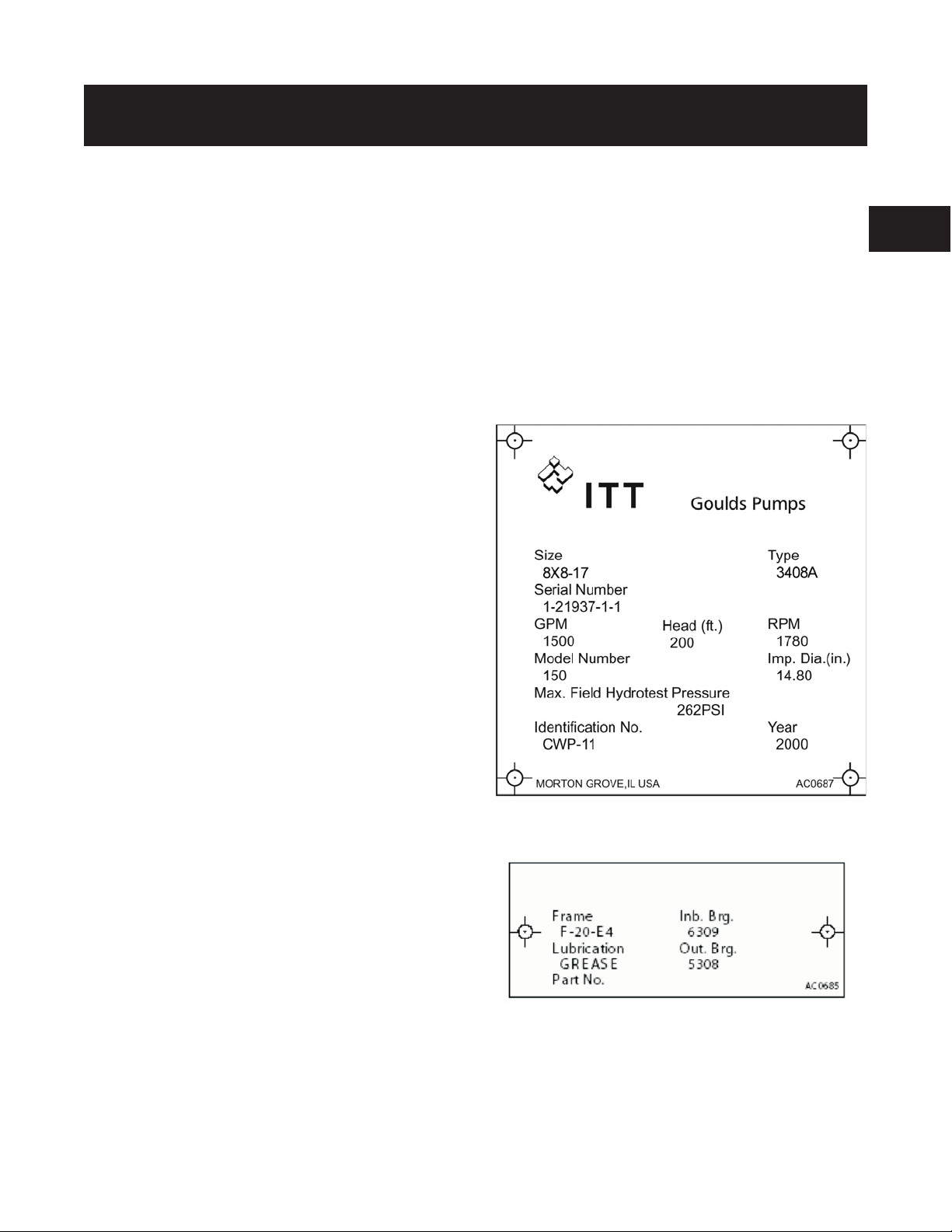
PUMP IDENTIFICATION
Pumps are designated by a series of numbers such as
3408A. The pump nameplate gives identification and rating
information as identified in Figure 1.
Permanent records for this pump are kept by serial number
and it must be used with all correspondence and spare parts
orders.
The frame plate shown in Figure 1A, gives information
concerning the bearings and their lubrication. The inboard
and outboard bearing numbers refer to the bearing
manufacturer’s numbers.
1
75# Maximum Suction Pressure
Listed on pump nameplate.
SEAL OPERATING LIMITS
Standard Self Flushing Mechanical Seals
BUNA-PH Limitations 7-9; Temperature Range -20 to
+225°F
EPT-PH Limitations 7-11; Temperature Range -20 to
+250°F
For use on closed or open systems which are relatively free
of dirt and/or other abrasive particles.
Figure 1: Rating Plate
Figure 2: Frame Plate
3408A IOM 6/08 5
Page 14

6 3408A IOM 6/08
Page 15

SAFETY
! SAFETY INSTRUCTION
s
This safety alert symbol will be used in this manual and
on the pump safety instruction decals to draw attention
to safety related instructions. When used, the safety
alert symbol means Attention! Become Alert! Your
Safety Is Involved!
Failure to follow the instructions may result in a
safety hazard.
Your 3408A pump should have the safety instruction
decals in Figure 2 displayed. If the decals are missing or
illegible, contact your local Goulds Pumps representative
for a replacement.
2
Figure 2: Safety Instruction Decals
3408A IOM 6/08 7
Page 16

ADDITIONAL SAFETY INSTRUCTIONS
1. Electrical connections to be made by qualified
electrician in accordance with all national, state, and
local codes.
2. Motor must have properly sized starter with properly
sized heaters to provide overload and undervoltage
protection.
3. If pump, motor, or piping is operating at extremely
high or low temperatures, guarding or insulation is
required.
4. The maximum working pressure of the pump is listed
on the pump nameplate; do not exceed this pressure.
Electrical Safety
! WARNING
s
Electrical Shock Hazard
Electrical connections to be made by a qualified electri
cian in accordance with all applicable codes, ordinances, and good practices.
Failure to follow these instructions could result in serious personal injury or death, or property damage.
! WARNING
s
Electrical Overload Hazard
Three-phase motors must have properly sized heaters to
provide overload and under voltage protection. Sinlephase motors have built-in overload protectors.
Failure to follow these instructions could result in
serious personal injury or death, or property damage.
Mechanical Safety
! WARNING
s
Disconnect and lockout power before servicing.
Failure to follow these instructions could result in
serious personal injury or death, or property damage.
! WARNING
s
Excessive System Pressure Hazard
The maximum working pressure of the pump is listed
on the nameplate. Do not exceed this pressure.
Failure to follow these instructions could result in
serious personal injury or death, or property damage.
! WARNING
-
s
The heating of water and other fluids causes
volumetric expansion. The associated forces may cause
failure of system components and release of high
temperature fluids. This will be prevented by installing
properly sized and located compression tanks and
pressure relief valves.
Failure to follow these instructions could result in
serious personal injury or death, or property damage.
Unexpected Startup Hazard
Excessive Pressure Hazard
Volumetric Expansion
Thermal Safety
! WARNING
s
Extreme Temperature Hazard
If pump, motor, or piping is operating at extremely
high or low temperatures, guarding or insulation is
required.
Failure to follow these instructions could result in
serious personal injury or death, or property damage.
8 3408A IOM 6/08
Page 17

LOCATION
Locate the pump so there is sufficient room for inspection,
maintenance, and service. If the use of a hoist or tackle is
needed, allow ample head room.
! WARNING
s
Falling Objects Hazard
Eyebolts or lifting lugs, if provided are for lifting only
the components to which they are attached.
Failure to follow these instructions could result in
serious personal injury or death, or property damage.
If lifting of the entire pump is required, do so with slings
placed under the base rails as shown in Figure 3.
The best pump location for sound and vibration absorption
is on a concrete floor with subsoil underneath. If the pump
location is overhead, special precautions should be
undertaken to reduce possible sound transmission. Consult
a sound specialist.
If the pump is not on a closed system, it should be placed as
near as possible to the source of the liquid supply and
located to permit installation with the fewest number of
bends or elbows in the suction pipe.
! WARNING
s
Do not install and operate pumps, 3D valves, suction
diffusers, etc., in closed systems unless the system is
constructed with properly sized safety devices and
control devices. Such devices include the use of
properly sized and located pressure relief valves,
compression tanks, pressure controls, temperature
controls, and flow controls as appropriate. If the
system does not include these devices, consult the
responsible engineer or architect before making pumps
operational.
2
Figure 3: Lifting the Pump
The installation must be evaluated to determine that the Net
Positive Suction Head Available (NPSHA) meets or
exceeds the Net Positive Suction Head Required (NPSHR),
as stated by the pump performance curve. See the section
entitled Suction and Discharge Piping for more details
regarding proper suction piping installation.
3408A IOM 6/08 9
Page 18

10 3408A IOM 6/08
Page 19

GENERAL INSTRUCTIONS
PURPOSE OF THE MANUAL
This manual is furnished to acquaint you with some of the
practical ways to install, operate, and maintain this pump.
Read it completely before any installation, operation, or
maintenance on your unit and keep it handy for future
reference.
Equipment cannot operate well without proper care. To
keep this unit at top efficiency, follow the recommended
installation and servicing procedures outlined in this
manual.
WARRANTY
Refer to your local representative for warranty coverage.
RECEIVING THE PUMP
Check the pump for shortages and damage immediately
upon arrival. (An absolute must!) Prompt reporting of any
damage to the carrier’s agent, with notations made on the
freight bill, will expedite satisfactory adjustment by the
carrier.
Pumps and drivers are normally shipped from the factory
mounted on a base plate and painted with primer and one
finish coat. Couplings may either be completely assembled
or have the coupling hubs mounted on the shafts and the
connecting members removed. When the connecting
members are removed, they will be packaged in a separate
container and shipped with the pump or attached to the base
plate.
Shafts are in alignment when the unit is shipped; however,
due to shipping, the pumps may arrive misaligned.
Alignment must be established during installation. Goulds
Pumps has determined that proper and correct alignment
can only be made by accepted erection practices. (See the
Foundation, Baseplate Setting, and Coupling Alignment
sections.)
TEMPORARY STORAGE
If the pump is not to be installed and operated soon after
arrival, store it in a clean, dry place having slow, moderate
changes in ambient temperature. Rotate the shaft
periodically to coat the bearings with lubricant, to retard
oxidation and corrosion, and to reduce the possibility of
false brinelling of the bearings.
line) should not exceed the limits for which the pump was
sold.
The pump must be primed before starting. Whenever
possible, the pump should be located below the fluid level
to facilitate priming and assure a steady flow of liquid. This
condition provides a positive suction head on the pump. It
may also be possible to prime the pump by pressurizing the
suction vessel.
When installing the pump, consider its location in relation
to the system to assure that sufficient Net Positive Suction
Head (NPSH) at pump suction is provided. Available
NPSH must always equal or exceed the required NPSH of
the pump.
The pump should be installed with sufficient accessibility
for inspection and maintenance. A clear space with ample
head room should be allowed for the use of an overhead
crane or hoist sufficiently strong to lift the unit.
NOTE: Allow sufficient space to be able to dismantle
the pump without disturbing the pump inlet and
discharge piping.
Select a dry place above the floor level wherever possible.
Take care to prevent the pump from freezing during cold
weather when not in operation. Should the possibility of
freezing exist during a shut-down period, the pump should be
completely drained, and all passages and pockets where liquid
might collect should be blown out with compressed air.
Make sure there is a suitable power source available for the
pump driver. If motor driven, electrical characteristics
should be identical to those shown on the motor data plate.
FOUNDATION
A substantial foundation and footing should be built to suit
local conditions. It should form a rigid support to maintain
alignment. The pump assembly must be mounted to a
suitable foundation having a mass ³ 1.5 times the weight of
the unit.
The foundation should be poured without interruption to
within 1/2 to 1-1/2 inches of the finished height. The top
surface of the foundation should be well scored and
grooved before the concrete sets; this provides a bonding
surface for the grout.
3
LOCATION
The pump should be installed as near the suction supply as
possible, but no less than five suction diameters with the
shortest and most direct suction pipe practical. See the
section entitled Suction and Discharge Piping. The total
dynamic suction lift (static lift plus friction losses in suction
3408A IOM 6/08 11
Foundation bolts should be set in concrete as shown in
Figure 4. An optional 4-inch long tube around the bolts at
the top of the concrete will allow some flexibility in bolt
alignment to match the holes in the base plate. Allow
enough bolt length for grout, shims, lower base plate
flange, nuts and washers. The foundation should be
allowed to cure for several days before the baseplate is
Page 20

shimmed and grouted.
NOTE: Reasonable alignment is defined as that which
is mutually agreed upon by pump contractor and the
accepting facility (final operator). Final alignment
procedures are covered in the section entitled
Alignment Procedure.
5. Check to make sure the piping can be aligned to the
pump flanges without placing pipe strain on either
flange.
6. Grout in baseplate completely and allow grout to dry
thoroughly before attaching piping to pump. See the
section entitled Grouting Procedure. 24 hours is
sufficient time with approved grouting procedure.
Figure 4: Foundation
BASEPLATE SETTING (BEFORE
PIPING)
NOTE: This procedure assumes that a concrete
foundation has been prepared with anchor or hold
down bolts extending up ready to receive unit. It must
be understood that pump and motor have been
mounted and rough aligned at the factory. If motor is
to be field mounted, consult factory for recommendations. Goulds Pumps cannot assume responsibility for
final alignment.
Figure 5: Setting Baseplate and Grouting
1. Use blocks and shims under base for support at anchor
bolts and midway between bolts, to position base
approximately 1 inch above the concrete foundation,
with studs extending through holes in the baseplate.
2. By adding or removing shims under the base, level and
plumb the pump shaft and flanges.
3. Draw anchor nuts tight against base, and observe pump
and motor shafts or coupling hubs for alignment.
(Temporarily remove coupling guard for checking
alignment.)
4. If alignment needs improvement, add shims or wedges
at appropriate positions under base, so that retightening
of anchor nuts will shift shafts into closer alignment.
Repeat this procedure until a reasonable alignment is
reached.
GROUTING PROCEDURE
Grout compensates for uneven foundation, distributes
weight of unit, and prevents shifting. Use an approved,
non-shrinking grout, after setting and leveling unit. See
Figure 5.
1. Build strong form around the foundation to contain
grout.
2. Soak top of concrete foundation thoroughly, then
remove surface water.
3. Baseplate should be completely filled with grout.
4. After the grout has thoroughly hardened, check the
foundation bolts and tighten if necessary.
5. Check the alignment after the foundation bolts are
tightened.
6. Approximately 14 days after the grout has been poured
or when the grout has thoroughly dried, apply an oil
base paint to the exposed edges of the grout to prevent
air and moisture from coming in contact with the
grout.
ALIGNMENT PROCEDURE
NOTE: A flexible coupling will only compensate for
small amounts of misalignment. Permissible
misalignment will vary with the make of coupling.
Consult coupling manufacturer’s data when in doubt.
Allowances are to be made for thermal expansion during
cold alignment, so that the coupling will be aligned at
operating temperature. In all cases, a coupling must be in
alignment for continuous operation. Even though the
coupling may be lubricated, misalignment causes excessive
wear, vibration, and bearing loads that result in premature
bearing failure and ultimate seizing of the pump.
Misalignment can be angular, parallel, or a combination of
these, and in the horizontal and vertical planes. Final
alignment should be made by moving and shimming the
motor on the baseplate, until the coupling hubs are within
the recommended tolerances measured in total run-out. All
measurements should be taken with the pump and motor
foot bolts tightened. The shaft of sleeve bearing motors
should be in the center of its mechanical float.
12 3408A IOM 6/08
Page 21

NOTE: Proper alignment is essential for correct pump
operation. This should be performed after baseplate
has been properly set and grout has dried thoroughly
according to instructions. Final alignment should be
made by shimming driver only. Alignment should be
made at operating temperatures.
! WARNING
s
Unexpected Startup Hazard
Disconnect and lockout power before servicing.
Failure to follow these instructions could result in seri
ous personal injury or death, or property damage.
ANSI/OSHA COUPLER GUARD
REMOVAL/INSTALLATION
! WARNING
s
Unexpected Startup Hazard
Disconnect and lockout power before servicing.
Failure to follow these instructions could result in serious personal injury or death, or property damage.
NOTE: Do not spread the inner and outer guards more
than necessary for guard removal or installation.
Overspreading the guards may alter their fit and
appearance.
a. For pumps with a motor saddle support
bracket: Ensure the outer guard is straddling
the support arm, and install but do not tighten
the two remaining capscrews.
b. For pumps without a motor saddle support
bracket: Insert the spacer washer between the
holes located closest to the motor in the outer
guard, and install, but do not tighten, the two
remaining capscrews.
6. Position the outer guard so it is centered around
-
the shaft, and so there is less than a 1/4 inch of
the motor shaft exposed. On guards that utilize a
slotted support bracket, the inner guard will
have to be positioned so there is only a 1/4 inch
of the pump shaft exposed.
7. Holding the guard in this position, tighten the
three capscrews.
3
Removal
1. Remove the two capscrews that hold the outer
(motor side) coupler guard to the support
bracket(s).
2. Spread the outer guard and pull it off the inner
guard.
3. Remove the capscrew that holds the inner guard
to the support bracket.
4. Spread the inner guard and pull it over the
coupler.
Installation
1. Check coupler alignment before proceeding.
Correct if necessary.
2. Spread the inner guard and place it over the
coupler.
3. With the inner guard straddling the support
bracket, install a capscrew through the hole (or
slot) in the support bracket and guard located
closest to the pump. Do not tighten the
capscrew.
4. Spread the outer guard and place it over the
inner guard.
5. Install the outer guard capscrews as required for
your pump.
3408A IOM 6/08 13
Page 22

Figure 6: ANSI/OSHA Coupling Guard
Alignment Method 1
Straight Edge Alignment for Standard Sleeve Type Coupler
with Black Rubber Insert
See Figure 7.
Before aligning the coupler, make sure there is at least 1/8
inch end clearance between the sleeve and the two coupler
halves.
1. Check angular misalignment using a micrometer or
caliper. Measure from the outside of one flange to the
outside of the opposite flange at four points 90° apart.
DO NOT ROTATE COUPLER. Misalignment up to
1/64 inch per inch of coupler radius is permissible.
2. At four points 90° apart (DO NOT ROTATE
COUPLER), measure the parallel coupler
misalignment by laying a straight edge across one
coupler half and measuring the gap between the
straight edge and opposite coupler half. Up to a 1/64
inch gap is permissible.
Figure 8: Checking Alignment (Method 2)
Alignment Method 2
For Orange Hytrel Inserts, 3500 RPM Operation, or All
Other Coupler Types
See Figure 8.
1. Make sure each hub is secured to its respective shaft
and that all connecting and/or spacing elements are
removed at this time.
2. The gap between the coupling hubs is set by the
manufacturer before the units are shipped. However,
this dimension should be checked. Refer to the
Figure 7: Checking Alignment (Method 1)
coupling manufacturer’s specifications supplied with
the unit.
14 3408A IOM 6/08
Page 23

3. Scribe index lines on coupling halves as shown in
Figure 8.
4. Mount dial indicator on one hub as shown for parallel
alignment. Set dial to zero.
5. Turn both coupling halves so that index lines remain
matched. Observe dial reading to see whether driver
needs adjustment. See paragraph i below.
6. Mount dial indicator on one hub as shown for angular
alignment. Set dial to zero.
7. Turn both coupling halves so that index lines remain
matched. Observe dial reading to see whether driver
needs adjustment. See paragraph i below.
8. Assemble coupling. Tighten all bolts and set screw(s).
It may be necessary to repeat steps c through f for a
final check.
DOWELING
Dowel the pump and driving unit as follows:
1. Drill holes through diagonally opposite feet and into
the base. Holes must be of a diameter 1/64 inch less
than the diameter of the dowel pins. Clean out the
chips.
2. Ream the holes in feet and base to the proper diameter
for the pins (light push fit). Clean out the chips.
3. Insert pins to be approximately flush with feet.
SUCTION AND DISCHARGE PIPING
When installing the pump piping, be sure to observe the
following precautions:
Piping should always be run to the pump.
3
9. For single element couplings, a satisfactory parallel
misalignment is .004" T.I.R., while a satisfactory
angular misalignment is .004" T.I.R. per inch of radius
R. See Figure 8.
Final Alignment
Final alignment cannot be accomplished until the pump has
been operated initially for a sufficient length of time to
attain operating temperature. When normal operating
temperature has been attained, secure the pump to re-check
alignment and compensate for temperature accordingly. See
the section entitled Alignment Procedure.
! WARNING
s
Rotating Components Hazard
Do not operate pump without all guards in place.
Failure to follow these instructions could result in serious personal injury or death, or property damage.
OPTIONAL Alignment Procedure
If desired, the pump and motor feet can be doweled to the
base after final alignment is complete. This should not be
done until the unit has been run for a sufficient length of
time and alignment is within the tolerance. See the section
entitled Doweling.
Do not move pump to pipe. This could make final
alignment impossible.
Both the suction and discharge piping should be supported
independently near the pump and properly aligned, so that
no strain is transmitted to the pump when the flange bolts
are tightened. Use pipe hangers or other supports at
necessary intervals to provide support. When expansion
joints are used in the piping system, they must be installed
beyond the piping supports closest to the pump. Tie bolts
should be used with expansion joints to prevent pipe strain.
Do not install expansion joints next to the pump or in any
way that would cause a strain on the pump resulting from
system pressure changes. It is usually advisable to increase
the size of both suction and discharge pipes at the pump
connections to decrease the loss of head from friction.
Install piping as straight as possible, avoiding unnecessary
bends. Where necessary, use 45-degree or long sweep
90-degree fitting to decrease friction losses.
Make sure that all piping joints are air-tight.
Where flanged joints are used, assure that inside diameters
match properly.
Remove burrs and sharp edges when making up joints.
! CAUTION
$
Extreme Temperature and/or
Do not “spring” piping when making any connections.
Provide for pipe expansion when hot fluids are to be pumped.
Flying Debris Hazard
Eye protection and gloves required.
Failure to follow these instructions could result in
property damage and/or moderate personal injury.
NOTE: Pump may have been doweled to base at factory.
3408A IOM 6/08 15
Page 24

Suction Piping
When installing the suction piping, observe the
following precautions. See Figure 9.
The sizing and installation of the suction piping is
extremely important. It must be selected and
installed so that pressure losses are minimized and
sufficient liquid will flow into the pump when
started and operated. Many NPSH (Net Positive
Suction Head) problems can be attributed directly
to improper suction piping systems.
Friction losses caused by undersized suction piping can
increase the fluid’s velocity into the pump. As
recommended by the Hydraulic Institute, Standard
ANSI/HI 1.1-1.5-1994, suction pipe velocity should not
exceed the velocity in the pump suction nozzle. In some
situations pipe velocity may need to be further reduced to
satisfy pump NPSH requirements and to control suction
line losses. Pipe friction can be reduced by using pipes that
are one to two sizes larger than the pump suction nozzle in
order to maintain pipe velocities less than 5 feet/second.
Suction piping should be short in length, as direct as
possible, and never smaller in diameter than the pump
suction opening. If the suction pipe is short, the pipe
diameter can be the same size as the suction opening. If
longer suction pipe is required, pipes should be one or two
sizes larger than the opening, depending on piping length.
Suction piping for horizontal double suction pumps should
not be installed with an elbow close to the suction flange of
the pump, except when the suction elbow is in the vertical
plane. A suction pipe of the same size as the suction nozzle,
approaching at any angle other than straight up or straight
down, must have the elbow located 10 pipe diameters from
the suction flange of the pump. Vertical mounted pumps
and other space limitations require special piping.
There is always an uneven turbulent flow around an elbow.
When it is in a position other than the vertical it causes
more liquid to enter one side of the impeller than the other.
See Figure 10. This results in high unequalized thrust loads
that will overheat the bearings and cause rapid wear, in
addition to affecting hydraulic performance.
Figure 9: Suction Pipe Installations
(Piping supports not shown)
16 3408A IOM 6/08
Page 25

Figure 10:
Unbalanced loading of a double suction impeller due to
uneven flow around an elbow adjacent to the pump.
When operating on a suction lift, the suction pipe should
slope upward to the pump nozzle. A horizontal suction line
must have a gradual rise to the pump. Any high point in the
pipe will become filled with air and thus prevent proper
operation on the pump. When reducing the piping to the
suction opening diameter, use an eccentric reducer with the
eccentric side down to avoid air pockets.
c. Where two or more pumps are connected to the
same suction line, install gate valves so that any
pump can be isolated from the line. Gate valves
should be installed on the suction side of all
pumps with a positive suction pressure for
maintenance purposes. Install gate valves with
stems horizontal to avoid air pockets. Globe
valves should not be used, particularly where
NPSH is critical.
d. The pump must never be throttled by the use of
a valve on the suction side of the pump. Suction
valves should be used only to isolate the pump
for maintenance purposes, and should always be
installed in positions to avoid air pockets.
e. A pump drain valve should be installed in the
suction piping between the isolation valve and
the pump.
3
Discharge Piping
If the discharge piping is short, the pipe diameter
can be the same as the discharge opening. If the
piping is long, pipe diameter should be one or two
sizes larger than the discharge opening. On long
horizontal runs, it is desirable to maintain as even a
grade as possible. Avoid high spots, such as loops,
which will collect air and throttle the system or lead
to erratic pumping.
NOTE: When operating on suction lift, never use a
straight taper reducer in a horizontal suction line, as it
tends to form an air pocket in the top of the reducer
and the pipe.
To facilitate cleaning pump liquid passage without
dismantling pump, a short section of pipe (Dutchman or
spool piece), so designed that it can be readily dropped out
of the line, can be installed adjacent to the suction flange.
With this arrangement, any matter clogging the impeller is
accessible by removing the nozzle or pipe section.
Valves in Suction Piping
When installing valves in the suction piping, observe
the following precautions:
a. If the pump is operating under static suction lift
conditions, a foot valve may be installed in the
suction line to avoid the necessity of priming
each time the pump is started. This valve should
be of the flapper type, rather than the multiple
spring type, sized to avoid excessive friction in
the suction line. (Under all other conditions, a
check valve, if used, should be installed in the
discharge line. See the section entitled Valves in
Discharge Piping.
b. When foot valves are used, or where there are
other possibilities of “water hammer,” close the
discharge valve slowly before shutting down the
pump.
Valves in Discharge Piping
A triple duty valve should be installed in the
discharge. The triple duty valve placed on the pump
protects the pump from excessive back pressure, and
prevents liquid from running back through the pump
in case of power failure.
Pressure Gauges
Properly sized pressure gauges should be installed in
both the suction and discharge nozzles in the gauge
taps, provided on request. The gauges will enable
the operator to easily observe the operation of the
pump, and also determine if the pump is operating in
conformance with the performance curve. If
cavitation, vapor binding, or other unstable
operation should occur, widely fluctuating discharge
pressure will be noted.
Pump Insulation
On chilled water applications most pumps are
insulated. As part of this practice, the pump bearing
housings should not be insulated since this would
tend to trap heat inside the housing. This could lead
to increased bearing temperatures and premature
bearing failures.
3408A IOM 6/08 17
Page 26

18 3408A IOM 6/08
Page 27

OPERATION
PRE-START CHECKS
Before initial start of the pump, make the following
inspections:
1. Check alignment between pump and motor.
2. Check all connections to motor and starting device
with wiring diagram. Check voltage, phase, and
frequency on motor nameplate with line circuit.
3. Check suction and discharge piping and pressure
gauges for proper operation.
4. Turn rotating element by hand to assure that it rotates
freely.
5. Check driver lubrication.
6. Assure that pump bearings are properly lubricated.
7. Assure that coupling is properly lubricated, if required.
8. Assure that pump is full of liquid and that all valves
are properly set and operational; the discharge valve
must close, and the suction valve must be open. See the
section entitled. Priming.
9. Check rotation. Be sure that the drive operates in the
direction indicated by the arrow on the pump casing, as
serious damage can result if the pump is operated with
incorrect rotation. Check rotation each time the motor
leads have been disconnected.
! WARNING
s
Rotating Components Hazard
Do not operate pump without all guards in place.
Failure to follow these instructions could result in seri
ous personal injury or death, or property damage.
! CAUTION
$
Seal Damage Hazard
Do not run pump dry. Seal damage may occur.
Failure to follow these instructions could result in
property damage and/or moderate personal injury.
NOTE: Pump may have been doweled to base at factory.
PRIMING
If the pump is installed with a positive head on the suction,
it can be primed by opening the suction and vent valve and
allowing the liquid to enter the casing.
If the pump is installed with a suction lift, priming must be
done by other methods such as foot valves, ejectors, or by
manually filling the casing and suction line.
! WARNING
s
Rotating Components Hazard
Do not operate pump without all guards in place.
Failure to follow these instructions could result in seri
ous personal injury or death, or property damage.
STARTING
1. Close drain valves and valve in discharge line.
2. Open fully all valves in the suction line.
3. Prime the pump.
NOTE: If the pump does not prime properly, or loses
prime during start-up, it should be shutdown and the
condition corrected before the procedure is repeated.
4. When the pump is operating at full speed, open the
discharge valve slowly. This should be done promptly
after start-up to prevent damage to pump by operating
at zero flow.
-
4
OPERATING CHECKS
1. Check the pump and piping to assure that there are no
-
leaks.
2. Check and record pressure gauge readings for future
reference.
3. Check and record voltage, amperage per phase, and
kW if an indicating wattmeter is available.
4. Check bearings for lubrication and temperature.
Normal temperature is 180° maximum.
5. Make all pump output adjustments with the discharge
line.
! CAUTION
$
Cavitation Damage Hazard
Do not throttle the suction line to adjust the pump
output.
Failure to follow these instructions could result in
property damage and/or moderate personal injury.
3408A IOM 6/08 19
Page 28

FREEZE PROTECTION
Pumps that are shut down during freezing conditions
should be protected by one of the following methods.
1. Drain the pump; remove all liquids from the casing.
2. Keep fluid moving in the pump and insulate or heat the
pump to prevent freezing.
! CAUTION
$
Bearing/Seal Damage Hazard
Do not let heated pump temperature rise above 150°F.
Failure to follow these instructions could result in
property damage and/or moderate personal injury.
CHANGING ROTATION
3408A centrifugal pumps can be operated clockwise or
counterclockwise when viewed from the coupling end of
the pump. If you wish to reverse the suction and discharge
nozzles, this can be accomplished with the same pump as
follows:
1. Remove the impeller from the shaft, turn it 180° and
replace it on the shaft.
NOTE: The impeller can only come off from the
outboard end.
2. With the rotating element out of the casing, remove the
casing from the bedplate and turn 180°.
3. Set the rotating element back in the casing and
reassemble the pump.
NOTE: The impeller and casing are in the same
relationship to each other as they were originally. The
shaft and motor are also in the same relationship to
each other as they were originally.
4. Reassemble pump and realign the coupling as called
for in the alignment instructions.
! WARNING
s
Rotating Components Hazard
Do not operate pump without all guards in place.
Failure to follow these instructions could result in seri
ous personal injury or death, or property damage.
-
IMPORTANT: Refer to the disassembly and assembly
procedures section of this manual for proper
disassembly and assembly techniques:
Figure 11: Correct Relationship of Impeller and Casing
NOTE: Unless the motor rotation is reversed, the
impeller will run backward.
20 3408A IOM 6/08
Page 29

Figure 12: Main Joint Bolts
4
3408A IOM 6/08 21
Page 30

22 3408A IOM 6/08
Page 31

PREVENTIVE MAINTENANCE
TROUBLESHOOTING
Between regular maintenance inspections, be alert for signs of motor or pump trouble. Common symptoms are listed below.
Correct any trouble immediately and avoid costly repair and shutdown.
CAUSES CURES
No Liquid Delivered
1. Lack of prime Fill pump and suction pipe completely with liquid.
2. Loss of prime
3. Suction lift too high
4. Discharge head too high
5. Speed too low
6. Wrong direction of rotation Check motor rotation with directional arrow on pump casing.
7. Impeller completely plugged Dismantle pump and clean impeller. Not Enough Liquid Delivered
8. Air leaks in suction piping
9. Speed too low See item 5.
10. Discharge head too high See item 4.
11. Suction lift too high See item 3.
12. Impeller partially plugged See item 7.
13. Cavitation; insufficient NPSH (depending
on installation)
14. Defective impeller
15. Foot valve too small or partially obstructed
16. Suction inlet not immersed deeply enough
17. Wrong direction of rotation
Check for leaks in suction pipe joints and fittings; vent casing to remove
accumulated air.
If no obstruction at inlet, check for pipe friction losses. However, static
lift may be too great. Measure with mercury column or vacuum gauge
while pump operates. If static lift is too high, liquid to be pumped must be
raised or pump lowered.
Check pipe friction losses. Large piping may correct condition. Check
that valves are wide open.
Check whether motor is directly across-the-line and receiving full voltage.
Or frequency may be too low; motor may have an open phase.
Not Enough Liquid Delivered
If liquid pumped is water or other non-explosive, and explosive gas or
dust is not present, test flanges for leakage with flame or match, or by
plugging inlet and putting line under pressure. A gauge will indicate a
leak with a drop of pressure.
a. Increase positive suction head on pump by lowering pump.b. Sub-cool
suction piping at inlet to lower entering liquid temperature.c.
Pressurization suction vessel.
Inspect impeller, bearings and shaft. Replace if damaged or vane sections
badly eroded.
Area through ports of valve should be at least as large as area of suction
pipe – preferably 1-1/2 times. If strainer is used, net clear area should be 3
to 4 times area of suction pipe.
If inlet cannot be lowered, or if eddies through which air is sucked persist
when it is lowered, chain a board to suction pipe. It will be drawn into
eddies, smothering the vortex
Symptoms are an overloaded drive and about 1/3 rated capacity from
pump. Compare the rotation of the motor with the directional arrow on the
pump casing.
4
3408A IOM 6/08 23
Page 32

CAUSES CURES
18. Too small impeller diameter (probable
cause if none of the above)
19. Air leaks in suction piping See item 8.
Check with the factory to see if a larger impeller can be used; otherwise,
cut the pipe losses or increase the speed, or both as needed. Be careful not
to overload the driver.
Not Enough Pressure
20. Mechanical defects See items 14 and 15.
21. Obstruction in liquid passages
22. Air or gases in liquid (Test in laboratory,
reducing pressure on liquid to pressure in
suction line. Watch for bubble formation.)
23. Too small impeller diameter (Probable
cause if none above)
24. Speed too low See item 5.
Dismantle pump and inspect passages of impeller and casing. Remove
obstruction.
May be possible to overrate pump to the point where it will provide
adequate pressure despite condition. Better to provide gas separation
chamber on suction line near pump, and periodically exhaust accumulated
gas. See item 13.
See item 18.
Pump Operates For Short Time, Then Stops
25. Incomplete priming
26. Suction lift too high See item 3.
27. Air leaks in suction piping See item 8.
28. Air or gases in liquid See item 22.
Free pump, piping and valves of all air. If high points in suction line
prevent this, they need correcting. See the section entitled Suction Piping.
Pump Takes Too Much Power
29. Head lower than rating; thereby pumping
too much liquid
30. Cavitation See item 13.
31. Mechanical defects. See items 14 and 15.
32. Suction inlet not immersed enough See item 16.
33. Liquid heavier (in either viscosity or
specific gravity) than allowed for
34. Wrong direction of rotation See item 6.
35. Casing distorted by excessive strains from
suction or discharge piping
36. Shaft bent due to damage – through
shipment, operation, or overhaul
37. Mechanical failure of critical pump parts
38. Misalignment Realign pump and driver.
39. Speed may be too high (brake hp of pump
varies as the cube of the speed; therefore, any
increase in speed means considerable increase
in power demand.)
40. Electrical defects
41. Mechanical defects in turbine, engine or
other type of drive exclusive of motor
Machine impeller’s OD to size advised by factory.
Use larger driver. Consult factory for recommended size. Test liquid for
viscosity and specific gravity.
Check alignment. Examine pump for friction between impeller and
casing. Replace damaged parts.
Check deflection of rotor by turning on bearing journals. Total indicator
run-out should not exceed 0.002” on shaft and 0.004” on impeller wearing
surface.
Check bearings and impeller for damage. Any irregularity in these parts
will cause a drag on shaft.
Check voltage on motor.
The voltage and frequency of the electrical current may be lower than that
for which the motor was built; or there may be defects in motor. The
motor may not be ventilated properly due to a poor location.
If trouble cannot be located, consult factory.
24 3408A IOM 6/08
Page 33

MAINTENANCE
GENERAL MAINTENANCE
Operating conditions vary so widely that to recommend one
schedule of preventative maintenance for all centrifugal
pumps is not possible. Yet some sort of regular inspection
must be planned and followed. We suggest a permanent
record be kept of the periodic inspections and maintenance
performed on your pump. This recognition of maintenance
procedure will keep your pump in good working condition,
and prevent costly breakdown.
One of the best rules to follow in the proper maintenance of
your centrifugal pump is to keep a record of actual
operating hours. Then, after a predetermined period of
operation has elapsed, the pump should be given a
thorough inspection. The length of this operating period
will vary with different applications, and can only be
determined from experience. New equipment, however,
should be examined after a relatively short period of
operation. The next inspection period can be lengthened
somewhat. This system can be followed until a maximum
period of operation is reached which should be considered
the operating schedule between inspections.
MAINTENANCE OF PUMP DUE TO
FLOOD DAMAGE
The servicing of centrifugal pumps after a flooded
condition is a comparatively simple matter under normal
conditions.
place prior to its first operation. The bearings should be
watched the first hour or so after the pump has been started
to see that they are operating properly.
The importance of proper lubrication cannot be over
emphasized. It is difficult to say how often a bearing
should be greased, since that depends on the conditions of
operation. It is well advised to add one ounce of grease at
regular intervals, but it is equally important to avoid adding
too much grease. For average operating conditions, it is
recommended that 1 oz. of grease be added at intervals of
three to six months, and only clean grease be used. It is
always best if unit can be stopped while grease is added to
avoid overloading.
The grease relief plug should be removed from the
outboard bearing housing before adding new grease to the
bearing. The plug should then be left out until the pump is
run for a minimum of 2 hours and the system has reached
its normal operating temperature.
NOTE: Excess grease is the most common cause of
overheating.
A lithium-based NLGI-2 grade grease should be used for
lubricating bearings where the ambient temperature is
above -20°F. Grease lubricated bearings are packed at the
factory with Shell Alvania No. 2. Other recommended
greases are Texaco Multifak No. 2 and Mobilux No. 2
grease.
4
Bearings are a primary concern on pumping units. First,
dismantle the bearings; clean and inspect them for any
rusted or badly worn surfaces. If bearings are free from rust
and wear, reassemble and relubricate them with one of the
recommended pump lubricants. Depending on the length of
time the pump has remained in the flooded area, it is
unlikely that bearing replacement is necessary; however, in
the event that rust or worn surfaces appear, it may be
necessary to replace the bearings.
Next, inspect the stuffing box, and clean out any foreign
matter that might clog the box. Mechanical seals should be
cleaned and thoroughly flushed.
Couplings should be dismantled and thoroughly cleaned.
Any pump that is properly sealed at all joints and connected
to both the suction and discharge should exclude outside
liquid. Therefore, it should not be necessary to go beyond
the bearings, stuffing box, and coupling when servicing the
pump.
BEARING LUBRICATION – GREASE
Grease lubricated ball bearings are packed with grease at
the factory and ordinarily will require no attention before
starting, provided the pump has been stored in a clean, dry
Greases made from animal or vegetable oils are not
recommended due to the danger of deterioration and
forming of acid. Do not use graphite.
The maximum desirable operating temperature for ball
bearings is 180°F. Should the temperature of the bearing
frame rise above 180°F, the pump should be shut down to
determine the cause.
MECHANICAL SEALS
1. Mechanical seals are precision products and should be
treated with care. Use special care when handling
seals. Clean parts are essential to prevent scratching
the finely lapped sealing faces. Even light scratches on
these faces could result in leaky seals.
2. Normally, mechanical seals require no adjustment or
maintenance, except routine replacement of worn or
broken parts.
3. A mechanical seal which has been used should not be
put back into service until the sealing faces have been
replaced or relapped. (Relapping is generally
economical only in seals two inches in size and
above.)
3408A IOM 6/08 25
Page 34

CLEANING WITHOUT
DISMANTLING PUMP
A short section of pipe, so designed that it can be readily
dropped out of the line, can be installed adjacent to the
suction flange. With this arrangement, any matter clogging
the impeller is accessible by removing the pipe section.
SERVICE
If the pump cannot be freed of clogging after the above
methods have been tried, dismantle the unit as previously
described to locate the trouble.
Figure 13: Mechanical View
26 3408A IOM 6/08
Page 35

REPLACING MECHANICAL SEALS
AND BEARINGS
(without removing the upper half of the casing)
NOTE: In order to replace the mechanical seal and
bearing housing on the coupler end, you must use a
spacer type coupler.
! WARNING
s
Unexpected Startup Hazard
Disconnect and lockout power before servicing.
bolt in the center of the fixture to remove the bearing
and gland plate from the shaft. See Figures 15 and 16.
! CAUTION
$
Pump Damage Hazard
Failure to remove the socket-head capscrews before
trying to pull the bearings off could cause damage to
the pump.
Failure to follow these instructions could result in
moderate personal injury or property damage.
Failure to follow these instructions could result in seri
ous personal injury or death, or property damage.
! CAUTION
$
Extreme Temperature Hazard
Allow pump temperatures to reach acceptable levels
before proceeding. Open the drain valve. Do not
proceed until liquid stops coming out of the drain
valve. If liquid does not stop flowing from the drain
valve, isolation valves are not sealing and should be
repaired before proceeding. After liquid stops flowing
from drain valve, leave the valve open and continue.
Remove the drain plug located on the bottom of the
pump housing. Do not reinstall the plug or closethe
drain valve until reassembly is completed.
Failure to follow these instructions could result in
moderate personal injury or property damage.
1. Close valves on suction and discharge sides of pump.
If no valves have been installed, it will be necessary to
drain the system.
2. Remove the coupler guard. For spacer coupler, loosen
the capscrews which secure the coupler flanges to the
coupler hubs. Remove the coupler flanges and sleeve
by compressing the flanges and pulling out from
beneath the hubs or by loosening the Allen set screws
and sliding the hubs back on the shafts. Remove the
coupler hubs from the pump shaft. For non-spacer
couplers, loosen set screws and slide flanges back on
shafts and remove rubber element.
-
4
Figure 14: Dimensions for Universal Fixture
(PN: AC2394)
7. Remove the inboard bearing and gland plate in the
same manner.
NOTE: The locknut and lockwasher are not used on
the inboard bearing.
! CAUTION
$
Do not reuse the ball bearings
3. Remove the capscrews from each of the bearing
housings and remove the bearing housings by placing
two 2.0" long full-threaded capscrews or Allen set
screws in the jackscrew holes provided.
4. Bend back the lockwasher tab and remove both the
lockwasher and locknut from the outboard end of the
shaft (the opposite side of the coupling).
5. Remove the socket-head capscrews holding the gland
plates to the stuffing boxes.
6. Insert threaded rods into the tapped holes in the gland
plate and install a fixture on the threaded rods to use a
puller. See Figure 14 for Dimensions of Universal
Fixture (PN: AC2394). Using the puller, tighten the
3408A IOM 6/08 27
Figure 15: Removing bearing and gland plate
using universal fixture
Page 36

Figure 16: Gland plate and bearing removed
from stuffing box
8. Remove the mechanical seal head from the pump shaft.
NOTE: To ease in the removal of the mechanical seal
heads, you may want to use 2 Allen wrenches as hooks
or form hooks from wire.
9. Drive the lip-seals, the mechanical seal seats, from
each of the gland plates by tapping on them from the
rear.
10. Remove the O-rings from each of the gland plates.
ASSEMBLING MECHANICAL
SEALS AND BEARINGS
(without removing the upper half of the casing)
NOTE: All bearings, O-rings, and lip-seals should be
replaced with new parts during assembly. All usable
parts should be cleaned of foreign matter before
reassembly.
NOTE: Reassemble the pump by starting on the
outboard end (the end opposite the coupling). This end
locks the rotating element into position in the casing.
1. Press the stationary mechanical seal seat into the gland
plate until it bottoms out against the bore. Lightly
lubricate the bore to ease assembly. See Figure 17.
Figure 17: Assembling mechanical seal seat
into gland plate
2. Press a new lip seal into the gland plate. Before
installing the lip seal, lubricate the lip-seal with
lightweight oil.
NOTE: Lip seals should sit against machined shoulder
in the gland plate. The lip seal should face away from
the mechanical seal seat. See Figure 18.
Figure 18: Assembling lip seal into the gland plate
3. Lubricate and roll the O-ring into the groove in the
gland plate.
IMPORTANT: Steps 4 and 5 must be completed within
10 to 12 minutes to assure proper placement of the
mechanical seals.
4. Lightly coat the outboard end of the pump shaft with
P-80 Rubber Lubricant Emulsion, vegetable oil, or
equal and slide the mechanical seal head onto the shaft.
Do not compress the seal spring at this time.
28 3408A IOM 6/08
Page 37

! CAUTION
$
Use a flashlight and make sure the mechanical seal
spring is seated properly into the spring holder and
around the bellows of the mechanical seal before
continuing. Without properly seating the spring, the
seal will fail.
5. Slide the gland plate, over the shaft, being very careful
that the head and the seat of the mechanical seal do not
get damaged. Then press the gland plate with the
O-ring into the stuffing box and tighten the
socket-head capscrews.
NOTE: Because of the compression of the O-ring, it
may be difficult to press the O-ring into the stuffing
box. Use longer socket-head capscrews to start the
gland plate into the stuffing box. Draw-up the bolts
evenly until the gland plate is secure in the stuffing
box. To prevent the mechanical seal spring from
pushing the gland plate back out of the stuffing box,
remove one long socket-head capscrew at a time and
replace with a regular sockethead capscrew.
6. Heat the ball bearings using dry heat or 10% – 15%
soluble oil and water, or an induction heater.
! CAUTION
$
Do not exceed a temperature of 275°F
7. Fill up the lip seal cavity with approximately .50
ounces of grease.
11. Remove the grease relief plug; coat the inside of the
bearing housing with grease, and then slide the
housing into place over the bearing. Alternately tighten
the bearing housing capscrews so as not to “cock” the
bearing housing causing bearing to bind. Leave the
grease relief plug out of the outboard housing until the
pump is run for a minimum of two hours and the
system has reached its normal operating temperature.
NOTE: A locknut and lockwasher are not installed on
the inboard end of the pump shaft. It is acceptable to
leave the grease relief plug installed on the inboard
side for Step 11.
12. Repeat steps 1 through 11 for the inboard.
13. Reinstall the coupler, check for alignment, and install
the coupler guard. See the sections entitled Alignment
Procedure and ANSI/OSHA Coupler Guard
Removal/Installation.
4
8. Using gloves, slide the heated bearing onto the shaft
against the shaft shoulder. See Figure 19.
Figure 19: Installing Bearing
9. Install the locknut and lockwasher on the outboard end
of the shaft. Make certain that the locknut is secure and
bend over the tabs on the lockwasher. See Figure 20.
10. Allow the bearing to cool to room temperature. Coat
the exposed sides of the bearing with two or three
ounces of recommended grease. Drive as much grease
as possible into the bearing using a putty knife or
similar tool.
Figure 20: Installing Lockwasher and Locknut
3408A IOM 6/08 29
Page 38

30 3408A IOM 6/08
Page 39

DISASSEMBLY & REASSEMBLY
DISMANTLING THE PUMP
(when removing the rotating element of the pump is
required)
! WARNING
s
Unexpected Startup Hazard
Disconnect and lockout power before servicing.
Failure to follow these instructions could result in seri
ous personal injury or death, or property damage.
! CAUTION
$
Extreme Temperature Hazard
Allow pump temperatures to reach acceptable levels
before proceeding. Open the drain valve. Do not proceed
until liquid stops coming out of the drain valve. If liquid
does not stop flowing from the drain valve, isolation valves
are not sealing and should be repaired before proceeding.
After liquid stops flowing from drain valve, leave the valve
open and continue. Remove the drain plug located on the
bottom of the pump housing. Do not reinstall the plug or
close the drain valve until reassembly is completed.
Failure to follow these instructions could result in
moderate personal injury or property damage.
1. Close valves on suction and discharge sides of pump.
If no valves have been installed, it will be necessary to
drain the system.
2. Remove the coupler guard. For spacer couplers, loosen
the capscrews which secure the coupler flanges to the
coupler hubs. Remove the coupler flanges and sleeve
by compressing the flanges and pulling out from
beneath the hubs or by loosening the Allen set screws
and sliding the hubs back on the shafts. Remove the
coupler hub from the pump shaft. For non-spacer
couplers, loosen Allen set screws and slide flanges
back on shafts and remove rubber element.
3. Remove all casing main joint capscrews and dowel pins.
two capscrews in the jackscrew holes provided.
7. Bend back the lockwasher tab and remove both the
lockwasher and locknut from the outboard end of the
shaft (the opposite side of the coupling).
8. Remove the capscrews holding gland plate to the
stuffing box.
-
9. Insert threaded rods into the tapped holes in the gland
plate and install a fixture on the threaded rods to use as
a puller. See Figure 14 for dimensions of Universal
Fixture. Using the puller, tighten the bolt in the center
of the fixture to remove the bearing and gland plate
from the shaft. If the bearing does not come off the
shaft, insert a spacer between the center bolt and the
shaft, and retighten the bolt. Remove the inboard
bearing and gland plate in the same manner. See
Figures 15 and 16.
NOTE: The locknut and lockwasher are not used on
the inboard bearing.
10. Remove the gland plates from the stuffing boxes and
remove the O-rings from the stuffing boxes.
! CAUTION
$
Do not reuse the ball bearings
11. Remove the mechanical seal head from the pump shaft.
12. Drive the lip-seals, the mechanical seal seats, from
each of the gland plates by tapping on them from the
rear.
13. Remove the O-rings from each of the gland plates.
14. Remove the two casing rings from the impeller and
remove the O-rings from each of the casing rings.
15. Remove the impeller-retaining ring with retaining
pliers. See Figure 22. Heat the impeller hub on both
ends to 350°F maximum, and pull or push the impeller
from the shaft. (Instead of heating the impeller, you
may press impeller off the shaft, if press is available.)
4
4. Tighten the jacking screws in the upper half of the
casing to separate the upper and lower casing halves.
Then lift off the upper half of the casing.
5. Tap the stuffing boxes with a soft-headed hammer to
break the seal between the stuffing box and lower
casing half, and lift the rotating element out of the
lower casing. Rotating element may be removed to a
suitable location for repair.
NOTE: A spare rotating element can be installed at this
point. See Figure 21.
6. Remove the capscrews from each of the bearing
housings and remove the bearing housings by placing
3408A IOM 6/08 31
NOTE: Press away from the coupling end.
NOTE: For impellers with replaceable rings; remove
the rings, if necessary, by cutting with a cold chisel.
16. Remove the impeller key from the shaft.
Page 40

Figure 21: Rotating Element
REASSEMBLING THE PUMP
(when removing the rotating element of the pump is
required)
NOTE: All bearings, O-rings, lip-seals, mechanical
seals, gaskets, impeller rings, and casing rings should
be replaced with the new parts during assembly. All
reusable parts should be cleaned of all foreign matter
before reassembling. The main casing joint gasket can
be made using the upper and lower half as a template.
Lay the gasket material on the casing joint. Trim the
gasket by lightly tapping with a ball peen hammer so
that it is flush with the inside edges of the casing. See
Figure 23. Do not hit casing edge with hammer hard
enough to round edge.
NOTE: Precut-casing gaskets can be ordered to
minimize the amount of trimming.
1. Before assembling the rotating element prepare the
casing and install the casing gaskets to the parting line.
2. Clean the gasket surfaces of the casing. Apply Scotch
3M-77 spray adhesive or equivalent to the lower half
of the casing.
3. Within one minute of spraying, set the untrimmed
gaskets in place on the lower half of the casing, align
the holes in the gaskets with the holes in the casing,
and press the gaskets firmly against the lower half of
the casing face in the area coated by the adhesive.
Figure 22: Removing Impeller Retaining Ring
Figure 23: Trimming Casing Gasket
4. Trim the gaskets flush with the lower casing bores. See
Figure 23.
! CAUTION
$
Machined-casing bores must remain sharp at the
casing parting line. Gaskets must be flush with the
bore in order to contact O-rings. Leakage can result
around the stuffing box O-ring if this step is not
properly followed.
5. Assemble the impeller key in the shaft key slot.
NOTE: For impeller with replaceable rings, heat each
new ring (approximately 300°F-400°F for bronze) and
slide onto the impeller. Using gloves, hold rings against
the impeller shoulder until cool.
6. Check the impeller and casing to determine the correct
relationship. Heat the impeller evenly to 300°F
maximum to expand the bore. Impeller may be pressed
onto the shaft instead of heating if a suitable press is
available. See Figure 24.
7. Using gloves, from the outboard end, slide the impeller
on the shaft against the shaft shoulder, and install the
retaining ring.
8. Lubricate and roll an O-ring into the groove in each of
the casing rings. Then slide the casing rings over the
impeller.
9. Thoroughly clean the gland plates and stuffing boxes
to prevent dirt from entering the seal during startup.
32 3408A IOM 6/08
Page 41

Press the stationary mechanical seal seats into both of the
gland plates. Lightly lubricate the gland plates to ease
assembly. See Figure 17.
IMPORTANT: Steps 11 through 21 must be completed,
on the outboard end, within 10 to 12 minutes to assure
proper placement of the mechanical seals
11. Press new lip seals into the gland plates. Before
installing the lip seals, lubricate the lip seals with
lightweight oil.
NOTE: Lip seals should sit against the machined
shoulder in the gland plates. The lip seals should face
away from the mechanical seal seats. See Figure 18.
12. Lubricate and roll the O-rings into the grooves in each
gland plate.
13. Press the gland plates into the stuffing boxes and
secure using the socket-head capscrews.
NOTE: Because of the compression of the O-ring, it
may be difficult to press the O-ring into the stuffing
box. Use longer socket-head capscrews to start the
gland plate into the stuffing box. To prevent the
mechanical seal spring from pushing the gland plate
back out of the stuffing box, remove one long
socket-head capscrew at a time and replace with a
regular socket-head capscrew.
Figure 26: Installing Stuffing Box
14 Lubricate and roll the O-rings into the groove in each
stuffing box.
NOTE: At this point reassemble the rotating element
by starting on the outboard end first (the end opposite
the coupling) as this end locates the settings of the
mechanical seal.
15. Lightly coat the outboard end of the pump shaft with
P-80 Rubber Lubricant Emulsion, vegetable oil, or
equal and slide the mechanical seal head onto the shaft.
See Figure 25.
4
Figure 24: Pressing Impeller on Shaft
Figure 25: Installing Mechanical Seal Head
16. Slide the stuffing box, with the gland plate, fully on
the shaft, being very careful that the head and seat of
the mechanical seal do not get damaged.
NOTE: Compress the seal spring only as far as
required to install the bearings. See Figure 26.
17. Fill lip seal cavity with approximately .50 ounces of
grease.
18. Heat the ball bearings using dry heat to 10% – 15%
soluble oil and water, or an induction heater.
! CAUTION
$
Do not exceed a temperature of 275°F..
19. Using gloves, slide the heated bearing onto the shaft
against the shaft shoulder. See Figure 19.
20. Install the locknut and lockwasher on the outboard end
of the shaft. Make certain that the locknut is secure and
bend over the tabs on the lockwasher. See Figure 20.
21. Allow the bearing to cool to room temperature. Coat the
exposed sides of the bearing with two or three ounces of
recommended grease. Drive as much grease as possible
into the bearing using a putty knife or similar tool.
22. Remove the grease relief plug; coat the inside of the
bearing housing with grease and then slide the housing
into place over the bearing. Attach the bearing housing
to the stuffing box with the capscrews. Leave the
grease relief plug out of the outboard housing until the
pump is run for a minimum of two hours and the
system has reached its normal operating temperature.
3408A IOM 6/08 33
Page 42

NOTE: A locknut and lockwasher are not installed on
the inboard end of the pump shaft. It is acceptable to
leave the grease relief plug installed on the inboard
side for Step 22.
23. Repeat steps 15 through 22 for the inboard end.
IMPORTANT: Steps 15 through 25 and must be
completed within 10 to 12 minutes to assure proper
placement of the mechanical seal.
24. Reinstall the coupler on the end of the shaft.
25. Set the rotating element in the pump casing, assuring
correct rotation. Locate both stuffing box tongues in
their respective casing grooves. Locate the pins in the
stuffing box and the casing wear rings in their
respective slots at the casing parting surface. Correct
any O-ring bulging. See Figure 27.
! CAUTION
$
DO NOT CUT OR DAMAGE THE O-RINGS WHEN
LOWERING THE ROTATING ELEMENT INTO
POSITION. WHEN ALL FOUR ANTI-ROTATION
PINS ARE LOCATED CORRECTLY, THERE WILL
BE SOME CASING RING LOOSENESS.
26. Apply a small bead of Dow Corning RTV silicone
sealant or equal at the parting line on top of gasket at
the stuffing box O-rings. See Figure 28.
Figure 28: Adding Sealant
Figure 27: Rotating element inside casing
Figure 29: Casing Main Joint
27. Locate the upper half of the casing into place using the
tapered dowel pins and install the casing main joint
bolts. See Figure 29. The casing joints should be
tightened to the following torques: 140 ft.-lb.
minimum for 5/8"-11 hex head cap screws (Grade 5);
350ft.-lb. minimum for 7/8"-9 Ferry Cap Counterbore
screws (Grade 8). Bolt torquing pattern is shown in
Figure 12.
NOTE: Torque values are essential in obtaining proper
gasket compression so no leakage can occur at the
main joint.
28. Rotate the shaft by hand to assure that it turns
smoothly and it is free from rubbing or binding.
29. Reinstall the coupler, check for alignment, and install
the coupler guard. See the sections entitled Alignment
Procedure and ANSI/OSHA Coupler Guard
Removal/Installation.
34 3408A IOM 6/08
Page 43

SPARE AND REPAIR PARTS
ORDERING PARTS
The pumps covered by this manual have been designed and
built with certain replaceable wearing parts. The
recommended inventory of spare parts depends upon the
installation and the importance of continued operation.
For critical service requiring a minimum of down-time, a
complete or quick-change rotating element is
recommended.
For normal service, with repairs to be made in the field, the
following parts are recommended for stock.
1 set of bearings
•
1 set of wearing rings
•
1 set of casing gaskets, O-rings and lip seals
•
2 mechanical seals (complete)
•
Parts should be ordered as far in advance of their use as
possible since circumstances beyond the control of the
company may reduce existing stock. Not all parts are
stocked and must be manufactured for each order.
To facilitate rapid handling of your order for spare parts, be
sure to include the following information:
1. Serial number of the pump. (See the pump nameplate.)
2. Name of the part.
3. Quantity of each part.
4. Material desired. (Parts will be furnished in original
materials unless specified as a material change. All
material substitutions should be discussed with the
factory.)
DEALER SERVICING
If trouble occurs that cannot be rectified, contact your local
Goulds Pumps representative. The representative will need
the following information in order to provide assistance:
1. Complete nameplate data of the pump and motor.
2. Suction and discharge pipe pressure gauge readings.
3. Ampere draw of the motor.
4. A sketch of the pumping hook-up and piping.
Capscrew Torque (Foot-Pound)
Capscrew Diameter
Capscrew Type Head Marking
SAE Grade w 6 13 25 38 60 120 190 210 300
Brass Stainless Steel 4 10 17 27 42 83 130 200 300
SAE Grade 5 10 20 35 60 90 180 325 525 800
SAE Grade 8 13 28 43 75 115 225 370 590 895
1/4 5/16 3/8 7/16 1/2 5/8 3/4 7/8 1
3408A IOM 6/08 35
Page 44

HOW TO ORDER
When ordering parts call
1-800-446-8537
or your local Goulds Representative
EMERGENCY SERVICE
Emergency parts service is available
24 hours/day, 365 days/year...
Call 1-800-446-8537
Visit our website at www.gouldspumps.com
Form I3408A 6/08 © copyright 2008 Goulds Pumps, Incorporated
subsidiary of ITT Corporation
 Loading...