

Page 1
I
nstallation, Operation and Maintenance Instructions
Model 3408
© 1999 Goulds Pumps
Page 2

Pump Safety Tips
Safety Apparel:
Insulated work gloves when handling hot bearings
•
or using bearing heater
Heavy work gloves when handling parts with sharp
•
edges, especially impellers
Safety glasses (with side shields) for eye
•
protection, especially in machine shop areas
Steel-toed shoes for foot protection when handling
•
parts, heavy tools, etc.
Other personal protective equipment to protect
•
against hazardous/toxic fluids
Coupling Guards:
Never operate a pump without a coupling guard
•
properly installed
Flanged Connections:
Never force piping to make a connection with a pump
•
Use only fasteners of the proper size and material
•
Operation:
Do not operate below minimum rated flow, or with
•
suction/discharge valves closed
Do not open vent or drain valves, or remove plugs
•
while system is pressurized
Maintenance Safety:
Always lock out power
•
Ensure pump is isolated from system and pressure
•
is relieved before disassembling pump, removing
plugs, or disconnecting piping
Use proper lifting and supporting equipment to
•
prevent serious injury
Observe proper decontamination procedures
•
Know and follow company safety regulations
•
Observe all cautions and warnings highlighted in
pump Installation, Operation and Maintenance
Instructions.
Ensure there are no missing fasteners
•
Beware of corroded or loose fasteners
•
Page 3

FOREWORD
3408 IOM 03/99 3
This manual provides instructions for the Installation, Operation, and Maintenance of the
Goulds Model 3408 Double Suction, Horizontally Split Case Pump. This manual covers the
standard product plus common options that are available. For special options, supplemental
instructions are supplied. This manual must be read and understood before installation
and maintenance.
The design, materials, and workmanship incorporated in the construction of Goulds pumps
make them capable of giving long, trouble-free service. The life and satisfactory service of any
mechanical unit, however, is enhanced and extended by correct application, proper
installation, periodic inspection, condition monitoring and careful maintenance. This instruction
manual was prepared to assist operators in understanding the construction and the correct
methods of installing, operating, and maintaining these pumps.
ITT Industries - Goulds Pumps shall not be liable for physical injury, damage or delays
caused by a failure to observe the instructions for Installation, Operation, and
Maintenance contained in this manual.
Warranty is valid only when genuine ITT Industries - Goulds Pumps parts are used.
Use of the equipment on a service other than stated in the order will nullify the warranty,
unless written approval is obtained in advance from ITT Industries - Goulds Pumps.
Supervision by an authorized ITT Industries - Goulds representative is recommended to
assure proper installation.
Additional manuals can be obtained by contacting your local ITT Industries - Goulds
representative or by calling 1-(800)-446-8537.
THIS MAN UAL EX PLAINS
Proper In stal la tion
n
Start- up Pro ce dures
n
Op era tion Pro ce dures
n
Rou tine Main te nance
n
Pump Over haul
n
Trou ble shoot ing
n
Or der ing Spare or Re pair Parts
n
Page 4

4 3408 IOM 03/99
Page 5

TABLE OF CONTENTS
3408 IOM 03/99 5
SECTION
PAGE
7 SAFETY
1
9 GENERAL INFORMATION
11 INSTALLATION
23 OPERATION
27 PREVENTIVE MAINTENANCE
35 DISASSEMBLY & REASSEMBLY
57 APPENDIX
2
3
4
5
6
7
Page 6

6 3408 IOM 03/99
Page 7

SAFETY
3408 IOM 03/99 7
DEFI NI TIONS .................................. 7
GEN ERAL PRE CAU TIONS ........................... 7
DEFINITIONS
1
This pump has been designed for safe and reliable
operation when properly used and maintained in
accordance with instructions contained in this manual.
A pump is a pressure containing device with rotating
parts that can be hazardous. Operators and
maintenance personnel must realize this and follow
safety measures. ITT Industries - Goulds Pumps
shall not be liable for physical injury, damage or
delays caused by a failure to observe the instructions
in this manual.
Throughout this manual the words WARNING ,
CAUTION , and NOTE are used to indicate
procedures or situations which require special
operator attention:
! WARNING
▲
Warning is used to indicate the presence of a
hazard which can cause severe personal injury,
death, or substantial property damage if the
warning is ignored.
▲!
Caution is used to indicate the presence of a
hazard which will or can cause minor pe rsonal
injury or property damage if the warning
is ignored.
NOTE: Operating procedure, condition, etc.
which is essential to observe.
CAUTION
EXAMPLES
! WARNING
▲
Pump shall never be operated without coupling
guard installed correctly.
▲!
Throttling flow from the suction side may
cause cavitation and pump damage.
NOTE: Proper alignment is essential for long
pump life.
CAUTION
GENERAL PRECAUTIONS
! WARN ING
▲
Personal injuries will result if procedures
outlined in this manual are not followed.
NEVER operate pump without coupling guard
•
correctly installed.
NEVER operate pump beyond the rated conditions
•
to which the pump was sold.
NEVER start pump without proper prime (sufficient
•
liquid in pump casing).
NEVER run pump below recommended minimum
•
flow or when no liquid is in pump.
ALWAYS lock out power to the driver before
•
performing pump maintenance.
NEVER operate pump without safety devices installed.
•
NEVER operate pump with discharge valve closed.
•
NEVER operate pump with suction valve closed.
•
DO NOT change conditions of service without
•
approval of an authorized Goulds representative.
! Warn ing
▲
If pump is to be used on process fluids above
120° F, pump surface temperatures could be
warm enough to cause burns. We recommend
pump surfaces be insulated. Failure to follow
these instructions could result in severe
personal injury.
Page 8

8 3408 IOM 03/99
Page 9
GENERAL INFORMATION
3408 IOM 03/99 9
PUMP DE SCRIP TION .............................. 9
NAME PLATE IN FOR MA TION ......................... 10
PUMP DESCRIPTION
2
This product line consists of 39 sizes of double
suction, horizontally split case pumps from size
2 x 3-11 through size 10 x 12-18.
Casing - The casing shall be (close-grained cast iron
for working pressures up to 175 psig), (ductile iron for
working pressures up to 400 psig), and shall be of
axially-split design with suction and discharge flanges
and mounting feet cast integral with the lower half
casing. Tapped and plugged holes shall be provided
for priming, vent drain and gauge connections. Upper
half casing shall be removable without disturbing
suction or discharge piping. Flanges shall be of (125#)
(250#) ASA Standard. Suction and discharge shall be
on a common centerline in both the horizontal and
vertical planes.
Impeller - The impeller shall be of the enclosed
double suction type made of bronze non-overloading
in operating characteristics and statically and
hydraulically balanced. The impeller shall be keyed to
the shaft and positioned axially by the shaft sleeves
which are, in turn, locked in place by shaft nuts. Hub
shall have sufficient metal thickness to allow
machining for installation of impeller rings.
Shaft - The shaft shall be made of ( SAE-1045 steel
(316 stainless steel
steel) of ample size to operate under load with a
minimum of deflection.
Shaft Sleeves - The Shaft Sleeves shall be made of
(bronze) (316 stainless steel) (cast iron) (420
stainless steel, 500 Brinnell ) and shall protect the
shaft from wear and from contact with the pumped
liquid. Shaft sleeves shall be locked in place by
threaded, bronze shaft sleeve nuts. An O-ring shall be
furnished under sleeve to prevent leakage.
•) (heat treated 416 stainless
•)
Stuffing Box Housing / Bearing Brackets - The
Stuffing Box Housing / Bearing Brackets shall be
made of cast iron separate from the casing mounted
in cylindrical fits in the casing. Stuff box/bearing
brackets will be drilled and tapped for drain
connection.
Casing Rings - The casing rings shall be made of
(bronze) (cast iron) ( Nitronic 60 stainless steel) and
shall be installed with an anti-rotation device and
designed to restrict leakage across the ring fit.
Bearings - The bearing shall be grease lubricated (oil
optional) ball type, single row inboard, double row
outboard, selected to carry radial and thrust loads.
The outboard bearing shall be retained by bearing
locknut and lockwasher.
Bearing Housings - The bearing housings shall be
bolted to the ends of the bearing bracket/stuffing box
and shall be male-female fitted for a full 360 degrees
to assure positive alignment. The housings shall
provide a fit for the inboard bearing that allows
freedom for thermal expansion while the outboard
bearing shall be clamped in place to take all thrust
loads and keep the rotating element in its proper axial
location. Openings for adding new grease and
draining old grease shall be provided.
Baseplate - The baseplate shall be steel, sufficiently
rigid to support the pump and driver.
Coupling - Coupling shall be of the flexible type.
Coupling hubs shall be secured to the driver and
driven shafts by a setscrew located over the key.
Coupling Guard - The coupling guard shall be the all
metal type.
Rotation - Pump shall have clockwise or
counterclockwise rotation when viewed from its
driven end.
• AISI 4140 Steel is standard on 4 x 6-11, 6 x 8-12M, and 8 x 10-20S & L, 10 x 12-18. 1045 & 316SS are no t available for these sizes.
Page 10
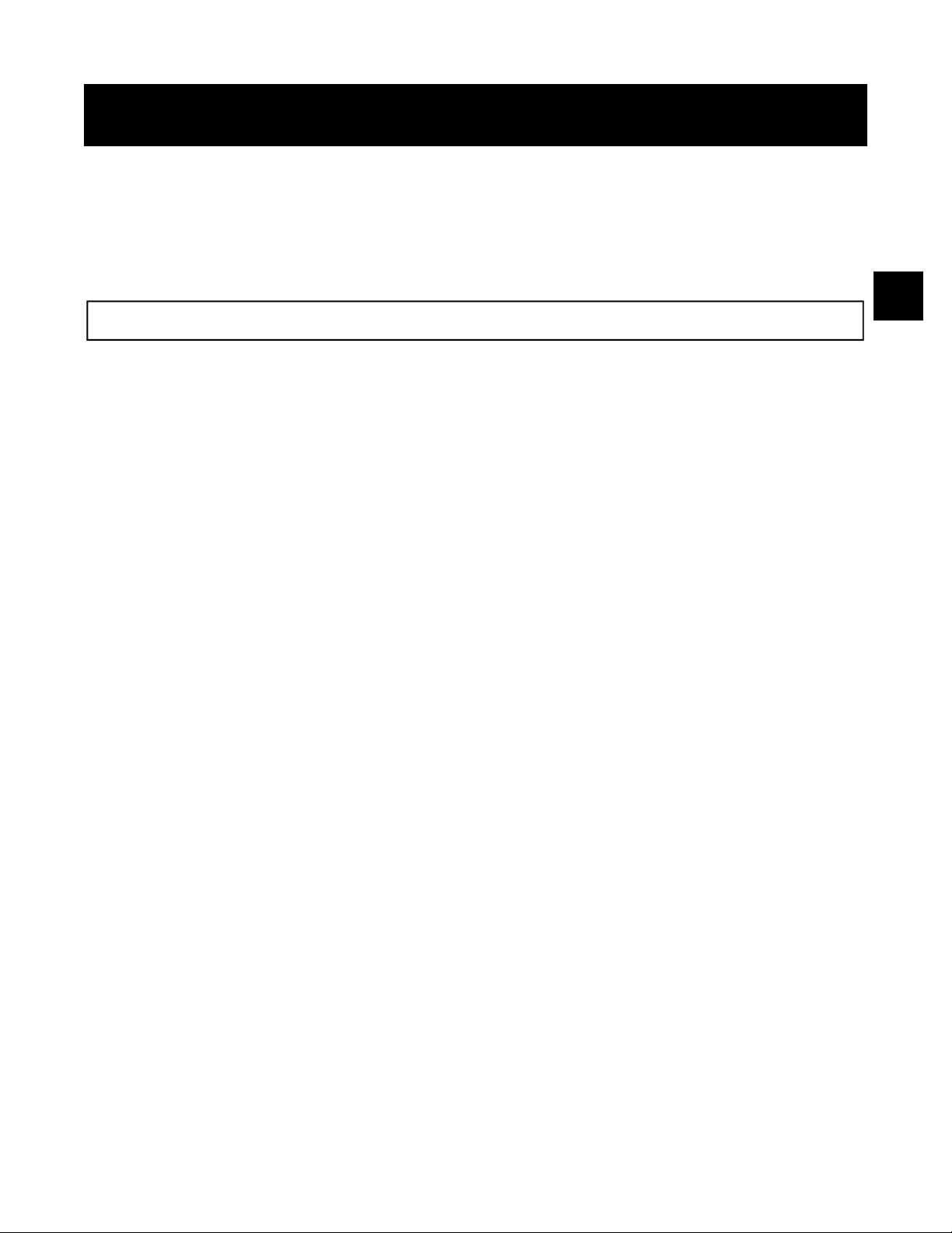
NAMEPLATE INFORMATION
Every pump has a Goulds nameplate that provides
information about the pump. The nameplate is located
on the pump casing.
Special tags which provide additional information
(mechanical seal data, etc.) and special tagging
required by customers are located on the pump
casing or on the bearing frame.
The standard nameplate (Fig. 1) provides information
about the pump size, type, serial number, rated head,
capacity, speed, impeller diameter, model number,
and maximum field hydrostatic test pressure.
The identification No. is a number which the end user
of pump requests to be put on the nameplate to
identify the pump in his operation.
The year indicates the year in which the pump was
built.
Rating and hydrostatic test pressure are expressed in
English units. Note the format of pump size:
Discharge x Suction - Nominal Impeller Diameter in
inches, for example, 2 x 3-11.
The frame plate (Fig. 2) provides information
concerning the bearings and their lubrication. The
inboard and outboard bearing numbers refer to the
bearing manufacturer’s numbers.
When ordering spare parts you will need to identify
pump model, size, serial number, and the catalog
number of required parts. Pump information can be
taken from the Goulds nameplate. Catalog numbers
can be found in this manual (Pg. 66).
Fig. 1
Fig. 2
10 3408 IOM 03/99
Page 11

INSTALLATION
3408 IOM 03/99 11
RE CEIVING THE PUMP ............................ 11
LIFTING THE PUMP .............................. 11
Hor i zon tal .................................. 11
Ver ti cal ................................... 12
STOR AGE ................................... 13
Tem po rary ................................. 13
Long Term ................................. 13
LO CA TION ................................... 14
FOUN DA TION ................................. 14
SETTING THE BASE PLATE ......................... 14
Grouting Pro ce dure ............................. 15
ALIGN MENT PRO CE DURE .......................... 15
Method One ................................. 16
Method Two ................................. 16
DOWELING .................................. 17
SUC TION AND DIS CHARGE PIPING ..................... 17
Suc tion Pip ing ................................ 17
Dis charge Pip ing .............................. 19
Pres sure Gauges .............................. 19
STUFFING BOX LU BRI CA TION ....................... 20
Packing ................................... 20
Me chan i cal Seals .............................. 21
Cartridge Seals ............................... 21
Cy clone Separators ............................. 21
3
RECEIVING THE PUMP
Check pump for shortages and damage immediately
upon arrival. (An absolute must!) Prompt reporting to
the carrier’s agent, with notations made on the freight
bill, will expedite satisfactory adjustment by the
carrier.
Pumps and drivers are normally shipped from the
factory mounted on a baseplate. Couplings may either
LIFTING THE PUMP
The following instructions are for the safe lifting of
your pump.
The unit should be unloaded and handled by lifting
equally at four or more points on the baseplate. The
lugs on the upper half casing are designed for lifting
the upper half casing only.
be completely assembled or have the coupling hubs
mounted on the shafts and the connecting members
removed. When the connecting members are
removed, they will be packaged in a separate
container and shipped with the pump or attached to
the baseplate.
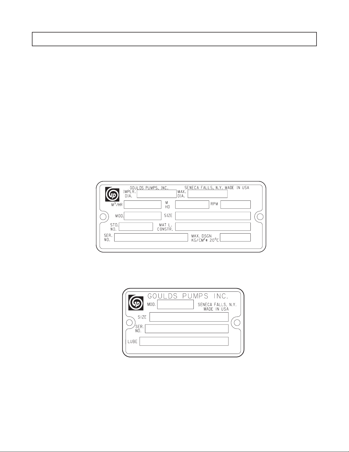
HORIZONTAL
Bare Pump (Model 100)
1. Using a nylon sling, chain, or wire rope, hitch
around both bearing housings. (See Fig. 3)
Page 12
12 3408 IOM 03/99
DO NOT LIFT
ENTIRE PUMP
WITH THESE
LUGS.
Pump, Base, and Driver (Model 150)
2. Care must be taken to size equipment for
unbalanced loads which may exist if the driver is
not mounted on the base at the time of lifting.
Driver may or may not be mounted at the factory.
Fig. 3
Using ANSI/OSHA Standard “S” hooks, place the “S”
hooks in the holes provided in the four corners of the base.
Be sure the points of the hooks do not touch the bottom of
the pump base. Attach nylon slings, chains, or wire rope to
the “S” hooks. Size the equipment for the load, and so the
lift angle will be less than 45° from the vertical.
Bases supplied without lifting holes
Place one sling around the outboard bearing housing.
! WARN ING
▲
Do not use lugs on top half of casing.
Place the remaining sling around the back end of the driver
as close to the mounting feet as possible. Make certain
sling will not damage housing cover or conduit boxes.
Join the free ends of the slings together and place over
the lifting hook. Use extreme care when positioning sling
under the driver so it cannot slip off. (See Fig. 5)
3. Pump, base, and driver assemblies where the
base length exceeds 100 inches may not be safe
to lift as a complete assembly. Damage to the
baseplate may occur. If the driver has been
mounted on the baseplate at the factory, it is safe
to lift the entire assembly. If driver has not been
mounted at the factory and the overall baseplate
length exceeds 100 inches, do not lift entire
assembly consisting of pump, base, and driver.
Instead lift the pump and baseplate to its final
location without the driver. Then mount the driver.
Bases supplied with lifting holes
Large bases are supplied with lifting holes in the
sides or the ends of the base. (See Fig. 4)
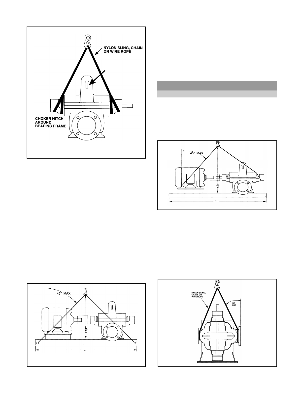
Fig. 5
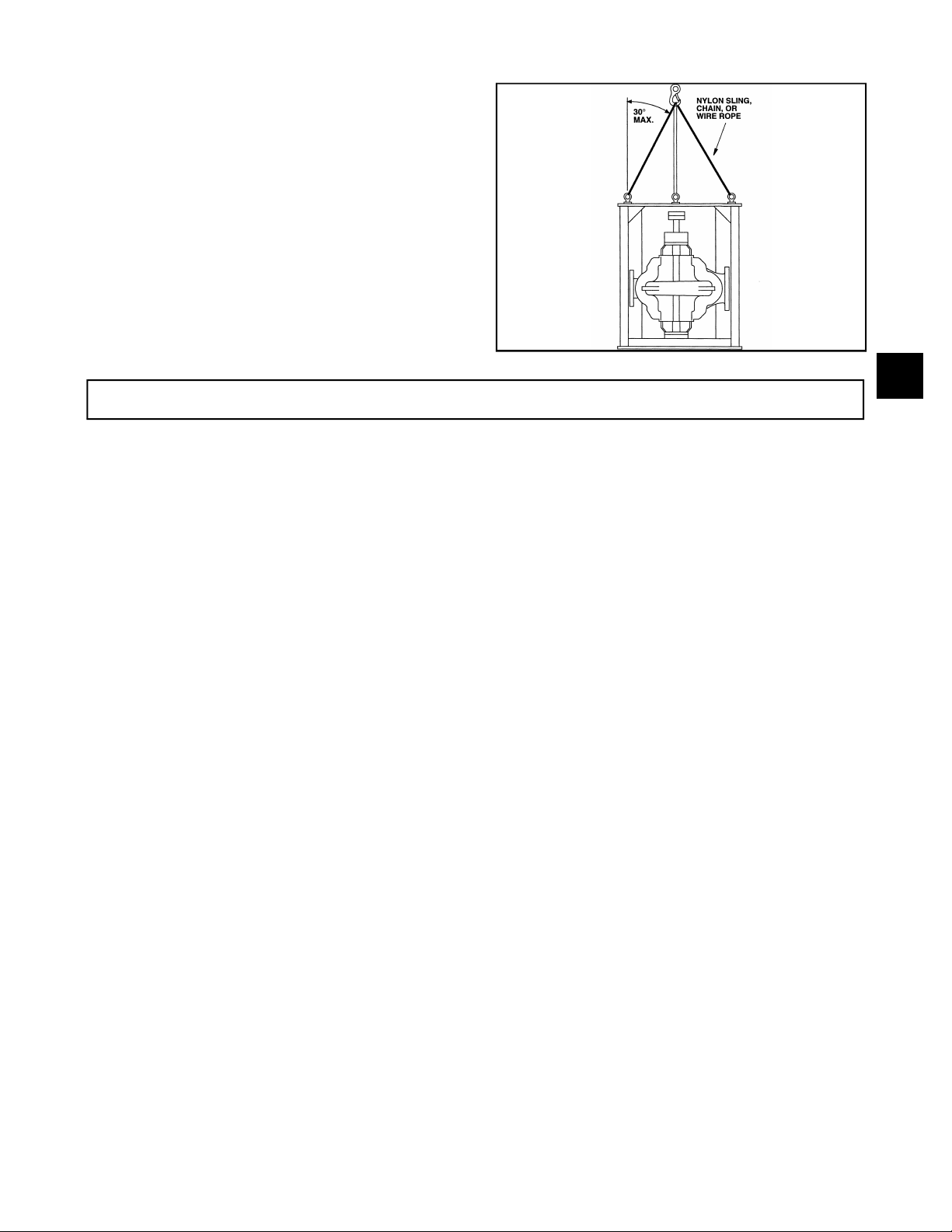
VERTICAL
Half Pedestal (Model 200)
1. Place nylon sling chain or wire rope around both
flanges. Use a latch hook or standard shackle and
end loops.
Be sure the lifting equipment is of sufficient length
to keep the lift angle less than 30° from the
vertical. (See Fig. 6)
Fig. 4
Fig. 6
Page 13
3408 IOM 03/99 13
Full Pedestal (Model 300)
2. Install eyebolts in the three holes provided at the top of
the support, being sure to tighten securely. Attach
chain or wire rope using latch hook or standard shackle
and end loop.
Be sure to use shoulder eyebolts that are
manufactured per ANSI B18.15 and sized to fit the
holes provided.
Be sure lifting equipment is of sufficient length to
keep the lift angle less than 30° from the vertical.
(See Fig. 7)
STORAGE
Fig. 7
3
The following storage procedures apply to the pump
only. Other accessories such as motors, steam
turbines, gears, etc., must be handled per the
respective manufacturer’s recommendations.
TEMPORARY
Temporary storage is considered one month or less.
If the pump is not to be installed and operated soon
after arrival, store it in a clean, dry place having slow,
moderate changes in ambient temperature. Rotate the
shaft periodically to coat the bearings with lubricant
and to retard oxidation, corrosion, and to reduce the
possibility of false brinelling of the bearings. Shaft
extensions and other exposed machine surfaces
should be coated with an easily removable rust
preventative such as Ashland Oil Tectyl No. 502C.
For oil lubricated bearings, fill the frame completely
with oil. Before putting equipment into operation, drain
the oil and refill to proper level.
LONG TERM
Storage longer than one month is considered long
term storage. Follow the same procedure for
temporary storage with the following addition. Add
one half ounce of a corrosion inhibiting concentrated
oil such as Cortec Corp. VCI-329 (for both grease and
oil lubricated bearings). Seal all vents and apply a
water proof tape around the oil seals in the bearing
frame. Remember for oil lubricated bearings to drain
the oil from the frame and refill to the proper level
before running pump.
Page 14
14 3408 IOM 03/99
LOCATION
The pump should be installed as near the suction
supply as possible, with the shortest and most direct
suction pipe practical. The total dynamic suction lift
(static lift plus friction losses in suction line) should not
exceed the limits for which the pump was sold.
The pump must be primed before starting. Whenever
possible, the pump should be located below the fluid
level to facilitate priming and assure a steady flow of
liquid. This condition provides a positive suction head
on the pump. It is also possible to prime the pump by
pressurizing the suction vessel.
When installing the pump, consider its location in
relation to the system to assure that sufficient Net
Positive Suction Head (NPSHA) is available at the
pump inlet connection. Available NPSH must always
equal or exceed the required NPSH ( NPSHR ) of the
pump.
FOUNDATION
The foundation must be substantial enough to absorb
vibration. ( Hydraulic Institute Standards recommends
the foundation weigh at least five (5) times the weight of
the pump unit.) It must form a permanent and rigid
support for the baseplate. This is important in
maintaining the alignment of a flexibly coupled unit.
The pump should be installed with sufficient accessibility
for inspection and maintenance. A clear space with ample
head room should be allowed for the use of an overhead
crane or hoist sufficiently strong to lift the unit.
NOTE: Allow sufficient space to be able to
dismantle pump without disturbing the pump inlet
and discharge piping.
Select a dry place above the floor level wherever
possible. Take care to prevent pump from freezing during
cold weather when not in operation. Should the possibility
of freezing exist during a shut-down period, the pump
should be completely drained, and all passages and
pockets where liquid might collect should be blown out
with compressed air.
Make sure there is a suitable power source available for
the pump driver. If motor driven, the electrical
characteristics of the power source should be identical to
those shown on motor data plate.
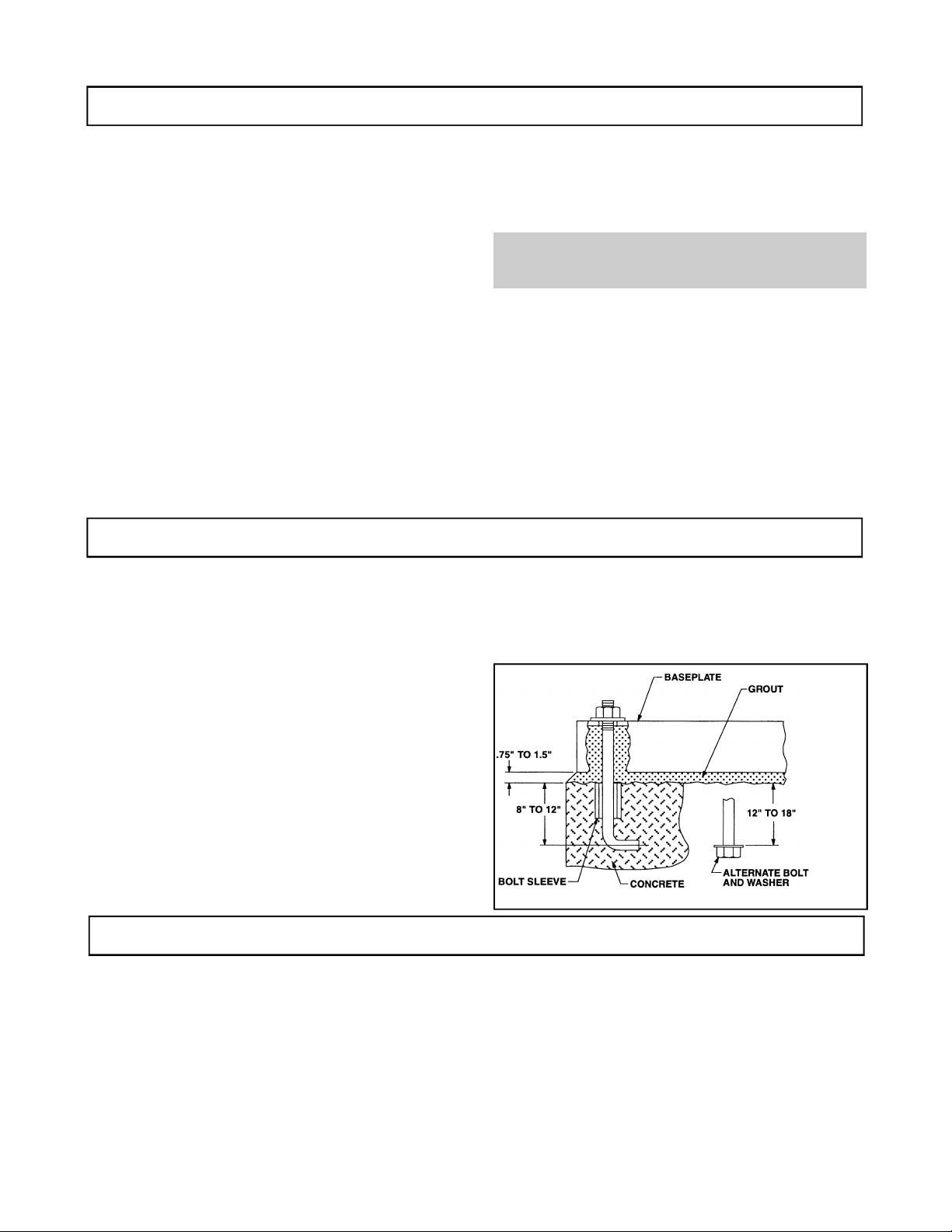
The foundation should be poured to within .75" - 1.5"
of the finished height. (See Fig. 8) Freshly poured
foundations should be allowed to cure for several
days before the unit is set in place and grouted.
Foundation bolts of the proper size should be embedded
in the concrete to a depth of eight (8) to twelve (12)
inches and locked with either a hook around a
reinforcing bar or alternatively, a nut and washer at the
bottom. The bolts should have a sleeve around them at
least six (6) times the bolt diameter in length and at least
two (2) bolt sizes larger in I.D. If a nut and washer are
used for locking, the washer should have an O.D. two
(2) sizes larger than the sleeve. Foundation bolts should
be sized .125" less than the anchor bolt holes in the
base.
SETTING THE BASEPLATE
Pump units are checked at the factory for align ability to
required tolerances.
Due to flexibility of an ungrouted base and handling in
shipment, it should not be assumed that the unit is in
alignment when it is placed on the rough foundation.
If these directions are followed, the required alignment
should be readily achieved.
Fig. 8
Initial or rough alignment must be done prior to grouting of
baseplate. Rough alignment is designated as .020" TIR
(Total Indicator Reading) parallel alignment and .009" TIR
per inch of radius angular alignment (See ALIGNMENT
PROCEDURE). Use blocks at anchor bolts and midway
between to position bottom of base at finished height
(See Fig. 9) with foundation bolts extending through holes
in the baseplate. Metal wedges with a small taper may be
used in lieu of blocks and shims.
Page 15

3408 IOM 03/99 15
NOTE: The baseplate does not have to be level.
After foundation bolts are lightly torqued , recheck
alignment requirements once more. Follow
requirements outlined at the beginning of this section.
If alignment must be corrected, add or remove shims
or wedges under the baseplate.
The unit can then be grouted. (See Fig. 9)
Grout compensates for the uneven foundation.
Together with the baseplate, it makes a very rigid
interface between the pump and the foundation
distributing the weight over the length of the base and
preventing shifting.
Fig. 9
If the unit has a non-flexible coupling (e.g. Falk Gear
coupling), the coupling halves should be disconnected;
this is generally not necessary on flexible type couplings
(e.g. Wood’s Sure-Flex coupling).
Tighten up all pump and motor bolts to assure they have
not loosened or a “soft foot” has occurred due to base
distortion in shipment. A “soft foot” causes a change in
the alignment when unloosening one bolt.
If the driver is being field installed, it should be centered in
its bolt holes with shims added to bring the driver into
rough alignment with the pump. (The pump may have to
be moved also.)
▲! CAUTION
Do not exceed six (6) shims, using as thick a
shim as possible, otherwise “sponginess” or
“soft foot” will result. Place thin shims in
between thick shims.
Level and plumb the pump shaft, coupling faces and
flanges by adding or removing shims between the blocks
and the bottom of the base. Hand tighten the anchor bolt
nuts at first. Being very careful not to distort the base,
snug down the nuts with a wrench. The non-flexible
coupling should not be reconnected until the alignment
operation has been completed.
Use an approved, non-shrinking grout such as
Embeco 636 or 885 by Master Builders, Cleveland,
Ohio or equivalent.
GROUTING PROCEDURE
1. Build a strong form around the foundation to
contain the grout.
2. Soak the top of the foundation thoroughly, then
remove surface water.
3. The baseplate should be completely filled with
grout and, if necessary, temporarily use air relief
tubing or drill vent holes to remove trapped air.
4. After the grout has thoroughly hardened
(approximately 24 hours), tighten the foundation
bolts fully.
5. Check the alignment after the foundation bolts
are tightened.
6. Approximately fourteen (14) days after the grout
has been poured and the grout has thoroughly
dried, apply an oil base paint to the exposed
edges of the grout to prevent air and moisture
from coming in contact with the grout.
3
ALIGNMENT PROCEDURE
Proper rough alignment must be made during unit
setting and grouting. See previous section.
There are two forms of misalignment between the
pump shaft and the driver shaft as follows:
1. Angular misalignment — shafts have axis
concentric at intersection, but not parallel.
2. Parallel offset misalignment — shafts have axis
parallel, but offset.
The necessary tools for checking alignment are: (1) a
straight edge and a taper gauge or set of feeler gauges
or, (2) a dial indicator with mounting magnet and
extension bars.
Check and correct for angular misalignment before
correcting parallel alignment. Final alignment should be
made by moving and shimming the motor on its base until
the coupling hubs are within the recommended tolerances
measured in total run out. All measurements should be
Page 16
16 3408 IOM 03/99
taken with the pump and driver bolts tightened. Final
alignment check should be made after the unit has
attained its final operating temperature.
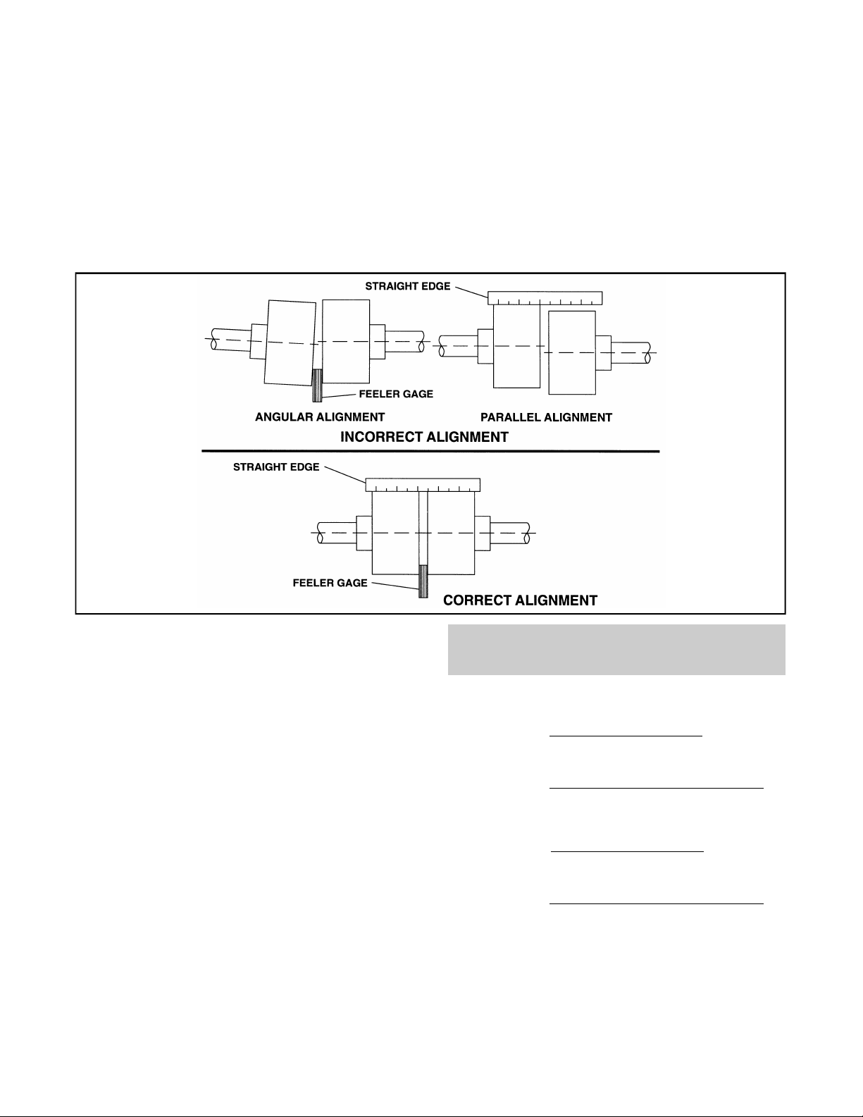
Method 1 - Using straight edge and taper gauges or
feelers (Fig. 10):
Proceed with this method only if satisfied that face
and outside diameters of the coupling halves are
square and concentric with the coupling bores. If this
condition does not exist or elastomeric couplings do
not make this method convenient, use Method 2.
Check for angular alignment by inserting the taper or
feeler gauges between the coupling faces at 90°
intervals. The unit is in angular alignment when these
four (4) measurements are the same, or within
recommended tolerances.
Check for parallel alignment by placing a straight
edge across both coupling rims on all four sides. The
unit is in parallel alignment when the straight edge
rests evenly across both coupling rims in all four (4)
positions.
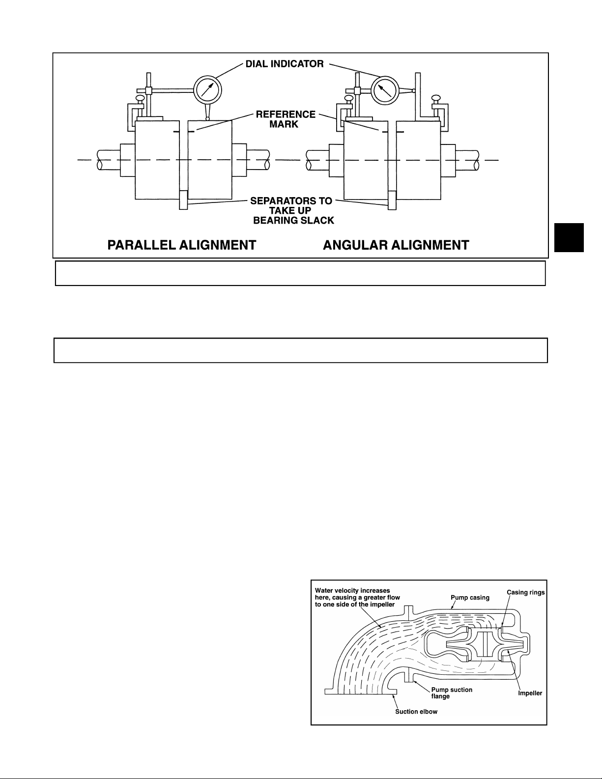
Method 2 - Dial Indicators (Fig. 11):
A dial indicator can be used to attain more accurate
alignment.
Fasten the indicator stand or magnetic base to the
pump half of the coupling and adjust the assembly
until the indicator button is resting on the other half
coupling periphery.
Set the dial to zero and chalk mark the coupling half
where the button rests. Also place a separator
between the coupling halves so bearing slack does
not affect the readings. (Chalk and separators are not
necessary on the elastomeric couplings that have not
been disconnected.) Rotate both shafts by the same
amount; i.e., all readings must be made with the
button on the chalk mark.
The dial readings will indicate whether the driver has
to be raised, lowered or moved to either side.
Accurate alignment of shaft centers can be obtained
with this method even where faces or outside
diameters of the coupling are not square or concentric
with the bores. After each adjustment, recheck both
parallel and angular alignments.
Fig. 10
NOTE: Gross deviations in squareness or
concentricity may cause rotation unbalance
problems and if so must be corrected.
Permissible Coupling Misalignment:
Parallel: Single element coupling:
.004" TIR (4 mils)
Double element (spacer) coupling:
.060" TIR per foot of spacer length
Angular: Single element coupling:
.004" TIP per inch of radius
Double element (spacer) coupling:
.002" TIR per inch of radius
Page 17
3408 IOM 03/99 17
DOWELING
Fig. 11
3
Pump units may, if desired, (or required in
specification) be doweled on diagonally opposite feet.
This should not be done until the unit has been run for
SUCTION AND DISCHARGE PIPING
The introduction of pumpage into a piping system which is
not well designed or adjusted may cause strain on the
pump, leading to misalignment or even impeller rubbing.
Since slight strain may go unnoticed, final alignment should
be done with the system full and up to final temperature.
Pipe flanges should not impose any strain on the pump.
This can be checked by a dial indicator. Any strain must be
corrected by adjustments in the piping system.
When installing the pump piping, be sure to observe the
following precautions:
Piping should always be run to the pump.
Do not move the pump to pipe. This could make final
alignment impossible.
Both the suction and discharge piping should be
independently anchored near the pump and properly
aligned so that no strain is transmitted to the pump when
the flange bolts are tightened. Use pipe hangers or other
supports at necessary intervals to provide support. When
expansion joints are used in the piping system they must be
installed beyond the piping supports closest to the pump.
Tie bolts and spacer sleeves should be used with
expansion joints to prevent pipe strain. Do not install
expansion joints next to the pump or in any way that would
cause a strain on the pump resulting from system pressure
changes. When using rubber expansion joints, follow the
recommendations of the Technical Handbook on Rubber
Expansion Joints and Flexible Pipe Connectors. It is usually
a sufficient length of time and alignment is within the
above alignment tolerance.
advisable to increase the size of both suction and discharge
pipes at the pump connections to decrease the loss of head
from friction.
Install piping as straight as possible, avoiding unnecessary
bends. Where necessary, use 45° or long radius 90° fittings
to decrease friction losses.
Make sure that all piping joints are air-tight.
Where flanged joints are used, assure that inside diameters
match properly.
Remove burrs and sharp edges when making up joints.
Do not “spring” piping when making any connections.
Provide for pipe expansion when hot fluids are to be
pumped.
Fig. 12
Page 18

Page 19

Page 20

18 3408 IOM 03/99
Suction Piping
When installing the suction piping, observe the following
precautions. (See Fig. 13)
The sizing and installation of the suction piping is
extremely important. It must be selected and installed so
that pressure losses are minimized and sufficient liquid
will flow into the pump when started and operated.
Many NPSH (Net Positive Suction Head) problems
can be directly attributed to improper suction piping
systems.
When installing valves in the suction piping, observe
the following precautions:
1. If the pump is operating under static suction lift
conditions, a foot valve may be installed in the
suction line to avoid the necessity of priming each
time the pump is started. This valve should be of
the flapper type, rather than the multiple spring
type, sized to avoid excessive friction in the
suction line. (Under all other conditions, a check
valve, if used, should be installed in the discharge
line. See Discharge Piping.)
Suction piping should be short in length, as direct as
possible, and never smaller in diameter than the
pump suction opening. A minimum of five (5) pipe
diameters between any elbow or tee and the pump
should be allowed. If a long suction pipe is required, it
should be one or two sizes larger than the suction
opening, depending on its length.
▲! CAUTION
An elbow should not be used directly before the
suction of a double suction pump if its plane is
parallel to the pump shaft. This can cause an
excessive axial load or NPSH problems in the pump
due to an uneven flow distribution. (See Fig. 12) If
there is no other choice, the elbow should have
straightening vanes to help evenly distribute the
flow.
Eccentric reducers should be limited to one pipe size
reduction each to avoid excessive turbulence and
noise. They should be of the conical type. Contour
reducers are not recommended.
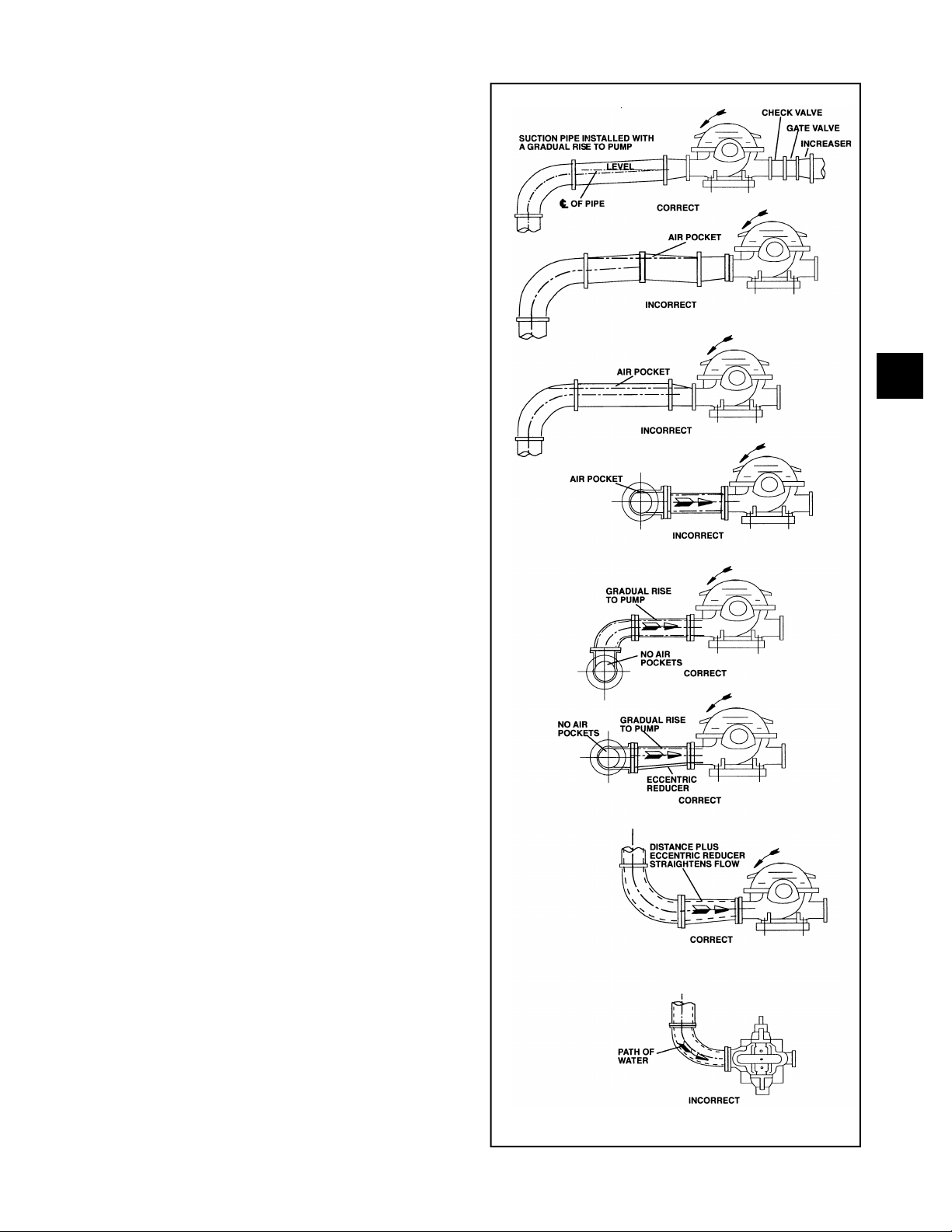
When operating on a suction lift, the suction pipe
should slope upward to the pump nozzle. A horizontal
suction line must have a gradual rise to the pump.
Any high point in the pipe can become filled with air
and prevent proper operation of the pump. When
reducing the piping to the suction opening diameter,
use an eccentric reducer with the eccentric side down
to avoid air pockets.
2. When foot valves are used, or where there are
other possibilities of “water hammer”, close the
discharge valve slowly before shutting down the
pump.
3. Where two or more pumps are connected to the
same suction line, install gate valves so that any
pump can be isolated from the line. Gate valves
should be installed on the suction side of all
pumps with a positive pressure for maintenance
purposes. Install gate valves with stems
horizontal to avoid air pockets. Globe valves
should not be used, particularly where NPSH is
critical.
4. The pump must never be throttled by the use of a
valve on the suction side of the pump. Suction
valves should be used only to isolate the pump
for maintenance purposes, and should always be
installed in positions to avoid air pockets.
3
NOTE: When operating on suction lift never
use a concentric reducer in a horizontal
suction line, as it tends to form an air pocket in
the top of the reducer and the pipe.
Fig. 13 shows some correct and incorrect suction
piping arrangements.
Page 21
3408 IOM 03/99 19
Discharge Piping
If the discharge piping is short, the pipe diameter can
be the same as the discharge opening. If the piping is
long, the pipe diameter should be one or two sizes
larger than the discharge opening. On long horizontal
runs, it is desirable to maintain as even a grade as
possible. Avoid high spots, such as loops, which will
collect air and throttle the system or lead to erratic
pumping.
A check valve and an isolating gate valve should be
installed in the discharge line. The check valve,
placed between pump and gate valve, protects the
pump from excessive back pressure, and prevents
liquid from running back through the pump in case of
power failure. The gate valve is used in priming and
starting, and when shutting the pump down.
Pressure Gauges
Properly sized pressure gauges should be installed in
both the suction and discharge nozzles in the gauge
taps provided. The gauges will enable the operator to
easily observe the operation of the pump, and also
determine if the pump is operating in conformance
with the performance curve. If cavitation, vapor
binding, or other unstable operation should occur,
widely fluctuating discharge pressure will be noted.
3
Fig. 13
Page 22

20 3408 IOM 03/99
STUFFING BOX LUBRICATION
Contaminants in the pumped liquid must not enter the
stuffing box. These contaminants may cause severe
abrasion or corrosion of the shaft, or shaft sleeve, and
rapid packing or mechanical seal deterioration; they
can even plug the stuffing box flushing and lubrication
system. The stuffing box must be supplied at all times
with a source of clean, clear liquid to flush and
lubricate the packing or seal. The most important
consideration is to establish the optimum flushing
pressure that will keep contaminants from the stuffing
box cavity. If this pressure is too low, fluid being
pumped may enter the stuffing box. If the pressure is
too high, excessive packing or seal wear may result;
and extreme heat may develop in the shaft causing
higher bearing temperatures. The most desirable
condition, therefore, is to use a seal water pressure
15-20 psig above the maximum stuffing box pressure.
If the pump system pressure conditions vary, packing
adjustment becomes difficult. Consideration should be
given to using a mechanical seal. (See Mechanical
Seals.)
Packing
Standard pumps are normally packed before shipment . If the pump is installed within 60 days after
shipment, the packing will be in good condition with a
sufficient supply of lubrication. If the pump is stored
for a longer period, it may be necessary to repack the
stuffing box. In all cases, however, inspect the
packing before the pump is started.
NOTE: Packing adjustment is covered in the
MAINTENANCE SECTION of this manual.
On some applications, it is possible to use internal
liquid lubrication (pumped liquid) to lubricate packing.
Only when all of the conditions prevail, can this be
done:
1. Liquid is clean, free from sediment and chemical
precipitation and is compatible with seal
materials.
2. Temperature is above 32° F and below 160° F.
3. Suction pressure is below 75 psig .
4. Lubrication (pumped liquid) has lubricating
qualities.
5. Liquid is non-toxic and non-volatile.
When the liquid being pumped contains solids or is
otherwise not compatible with packing materials, an
outside supply of seal liquid should be furnished. In
general, external-injection liquid (from an outside
source) is required when any of the above conditions
cannot be met.
The standard stuffing box consists of rings of packing
(see assembly section for number of rings), a seal
cage (optional), and a gland. A shaft sleeve which
extends through the box and under the gland is
provided to protect the shaft.
A tapped hole is supplied in the stuffing box directly
over the seal cage to introduce a clean, clear sealing
medium. The stuffing box must, at all times, be
supplied with sealing liquid at a high enough pressure
to keep the box free from foreign matter, which would
quickly destroy the packing and score the shaft
sleeve.
Only a sufficient volume of sealing liquid to create a
definite direction of flow from the stuffing box inward
to the pump casing is required, but the pressure is
important. Apply seal water at a rate of approximately
.25 GPM at a pressure approximately 15 to 20 psig
above the suction pressure. (Approximately one (1)
drop per second.)
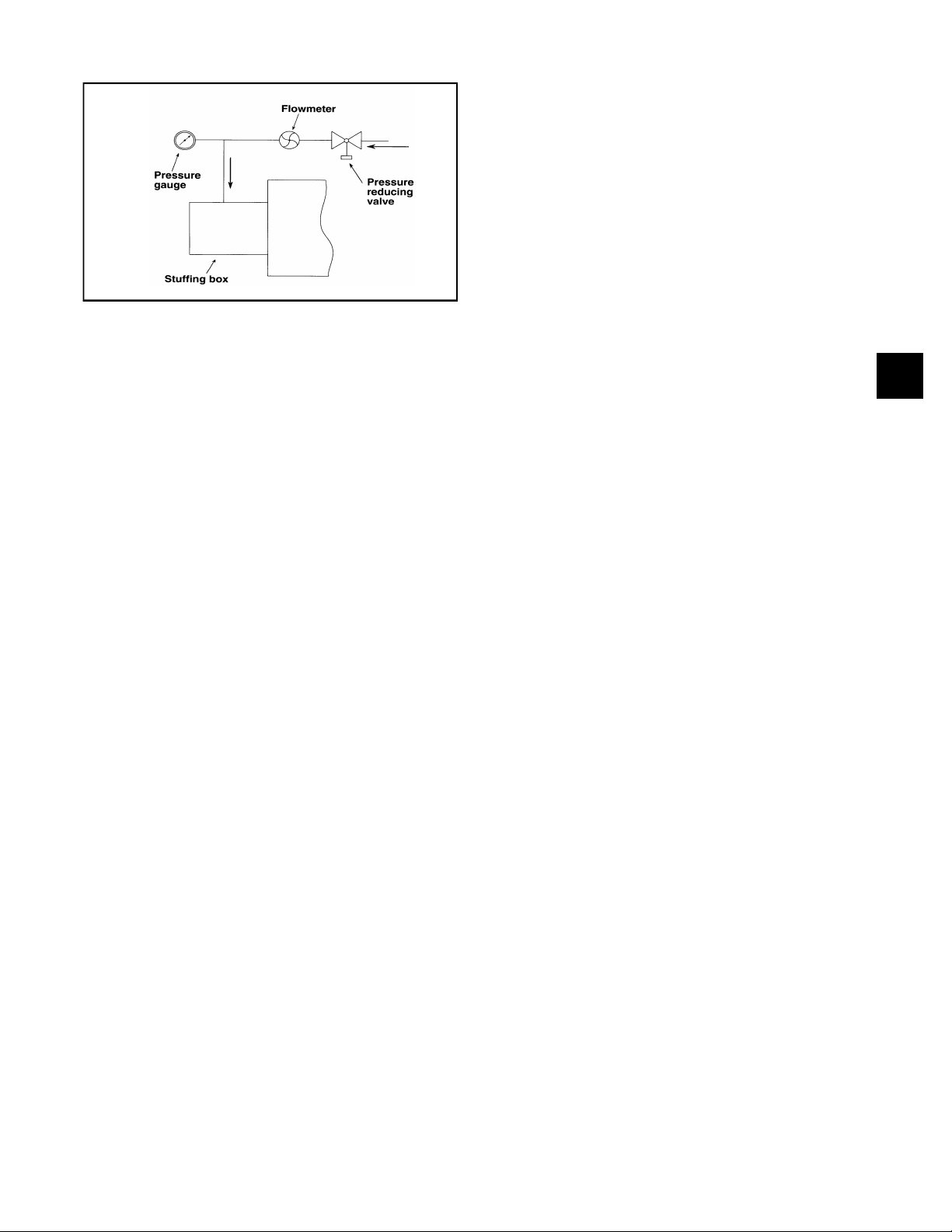
One recommended method to minimize error in
regulating flushing water is a “Controlled Pressure
System.” (Fig. 14) Most important is the pressure
reducing valve adjusted to a value slightly exceeding
the maximum stuffing box operating pressure
(assuming it is reasonably constant). A flow indicating
device will serve to indicate a failing of the bottom
packing rings allowing leakage in the pump.
External sealing liquid should be adjusted to the point
where the packing runs only slightly warm, with a very
slow drip from the stuffing box. Excess pressure from
an external source can be very destructive to packing.
More pressure is required, however, for abrasive
slurries than for clear liquids. Examination of the
leakage will indicate whether to increase or decrease
external pressure. If slurry is present in the leakage,
increase the pressure until only clear liquid drips from
the box. If the drippage is corrosive or harmful to
personnel, it should be collected and piped away.
A common error is to open the external piping valve
wide and then control the drippage by tightening the
packing gland. Actually, a combination of both
adjustments is essential to arrive at the optimum
condition. The life of packing and sleeve depends on
this careful control more than any other factor.
Page 23
3408 IOM 03/99 21
Pump
Casing
Fig. 14
Mechanical Seals
Mechanical seals are preferred over packing on some
applications because of better sealing qualities and
longer serviceability. Leakage is eliminated when a
seal is properly installed, and normal life is much
greater than that of packing on similar applications. A
mechanical shaft seal is supplied in place of a packed
stuffing box when specifically requested. The change
from packing to an alternate arrangement may be
made in the field by competent service personnel.
Conversion parts may be ordered from your Goulds
Pump Sales Representative.
Just as with packing, the mechanical seal chamber
must be supplied, at all times, with a source of clean,
clear liquid to flush and lubricate the seal. The most
important consideration is to establish the optimum
flushing pressure that will keep contaminants from the
seal cavity. If this pressure is too low, fluid being
pumped may enter the stuffing box. If the pressure is
too high, excessive seal wear may result.
When contaminants are present in the pumpage, an
external source of clean seal water must be supplied.
Supply approximately .25 GPM at a pressure
approximately 15 to 20 psig above the suction
pressure.
Fig. 14 shows the recommended “Controlled Pressure
System” for a mechanical seal. Seal water enters the
seal chamber, lubricates the seal face, and exits into
the pump itself. Positive flow in the seal water line
indicates adequate seal water pressure.
Cartridge Seals
Follow the appropriate lubrication directions for
mechanical seals given in this section. Most cartridge
seals provide flushing connections on their glands.
Use the cartridge seal gland flushing taps (if provided)
for your seal water connections instead of the stuffing
box tap. The quench taps on the glands (if present)
are normally only used in chemical applications.
Consult seal manufacturer’s literature for more
detailed information.
Cyclone Separator
If the fluid being pumped contains sediment and there
is no external, clean water source available to flush
the mechanical seals, a cyclone separator can be
used to remove most of the sediment from the liquid
being pumped so it can be used to flush the seals.
The separator is placed in the seal water piping line
and removes the sediment to an external drain
(normally back to the pump suction line).
3
Page 24

22 3408 IOM 03/99
Page 25

OPERATION
3408 IOM 03/99 23
PRE-START CHECKS ............................. 23
PRIMING .................................... 23
Flushing ................................... 23
Fill ing .................................... 23
STARTING ................................... 24
OP ER A TIONAL CHECK LIST ......................... 24
SHUT DOWN .................................. 25
FREEZE PRO TEC TION ............................ 25
FIELD TESTS ................................. 25
PRE-START CHECKS
Before the initial start of the pump, make the following
inspections:
1. Check alignment between pump and driver. See the
section on alignment for alignment requirements.
2. Check all connections to motor and starting device
with wiring diagram. Check voltage, phase, and
frequency on motor nameplate with line circuit.
3. Check suction and discharge piping and pressure
gauges for proper operation.
4. Turn rotating element by hand to assure that it rotates
freely.
5. Check stuffing box adjustment, lubrication, and
piping.
PRIMING
If the pump is installed with a positive head on the
suction, it can be primed by opening the suction
valve, and loosening the vent plug on the top of the
casing (Do not remove), allowing air to be purged
from the casing.
If the pump is installed with a suction lift, priming must
be done by other methods such as foot valves,
ejectors, or by manually filling the casing and suction
line.
▲! CAUTION
Under either condition, the pump must be
completely filled with liquid before starting. The
pump must not be run dry in the hope it will
prime itself. Serious damage to the pump may
result if it is started dry.
6. Check driver lubrication.
4
7. Assure that pump bearings are properly lubricated.
8. Assure that coupling is properly lubricated, if required.
9. Assure that pump is full of liquid and all valves are
properly set and operational, with the discharge valve
and the suction valve open. Purge all air from top of
casing.
10. Check rotation. Be sure that the driver operates in the
direction indicated by the arrow on the pump casing
as serious damage can result if the pump is operated
with incorrect rotation. Check rotation each time the
motor leads have been disconnected.
FLUSHING
New and old systems should be flushed to eliminate all
foreign matter. Heavy scale, welding splatter and wire or
other large foreign matter can clog the pump impeller.
This will reduce the capacity of the pump causing
cavitation, excessive vibration, and/or damage to close
clearance parts (wear rings, seals, sleeves, etc.)
FILLING
Vents should be located at the highest point so entrained
gases and air can escape. However, if the gases are
flammable, toxic, or corrosive they should be vented to an
appropriate place to prevent harm to personnel or other
parts of the system. Pipe hangers and anchors should be
checked to make sure they are properly set to take the
additional weight of the pumpage.
Page 26

24 3408 IOM 03/99
All drains should be closed when filling the system.
Filling should be done slowly so that excessive velocities
do not cause rotation of the pumping elements which
may cause damage to the pump or its driver. The
adequacy of the anchors and hangers may be checked
by mounting a dial indicator off of any rigid structure not
STARTING
tied to the piping and setting the indicator button on the
pump flange in the axial direction of the nozzle. If the
indicator moves, as the filling proceeds, the anchors and
supports are not adequate or set properly and should be
corrected.
1. Close drain valves.
2. Open fully all valves in the suction and discharge
lines.
3. Turn on seal water to the stuffing box. (If pumped
fluid is dirty or if leaking of air is to be prevented,
these lines should be always left open.)
4. Prime the pump.
NOTE: If the pump does not prime properly,
or loses prime during start-up, it should be
shutdown and the condition corrected before
the procedure is repeated.
OPERATIONAL CHECKLIST
1. Driver/Pump Rotation
Check rotation each time the motor leads have
been disconnected. Be sure that the driver
operates in the direction indicated by the arrow on
the pump casing. Rough operation and extreme
vibration can result if the pump is operated in the
wrong direction.
5. Start the pump driver (turbines and engines may
require warming up; consult the manufacturer’s
instructions).
6. When the pump is operating at full speed, check
to see that the check valve has opened up. Check
valve must open 5 seconds or less after start-up
to prevent damage to pump by operating at zero
flow.
7. Adjust the liquid seal valves to produce the
recommended pressure for either the mechanical
seal or packed stuffing box.
5. Temperature
Check and record bearing temperatures using a
thermometer. Temperature should not exceed
180° F.
NOTE: Just because bearing housings are too
hot to touch does not mean that they are
running too hot for proper operation.
2. Stuffing Box Adjustment
Make stuffing box packing gland and lubrication
adjustments.
3. Flow
An accurate measurement of flow rate
(volume/time) is difficult in the field. Venturi
meters, flow nozzles, orifice plates, or timing the
draw down in the wet well are all possible
methods. Record any reading for future reference.
4. Pressure
Check and record both suction and discharge
pressure gauge readings for future reference.
Also, record voltage, amperage per phase,
kilowatts if an indicating wattmeter is available,
and pump speed.
6. Vibration and Sound
The acceptable vibration level of a centrifugal
pump depends on the rigidity of the pump and the
supporting structure. Recommended values for
vibration can vary between .20 ips (inches per
second) velocity to .60 ips velocity depending on
the operating characteristics and the structure.
Refer to the Centrifugal Pump section of the
Hydraulic Institute Standards for a complete
description and charts on various pumps.
Field sound levels are difficult to measure
because of background noise from piping, valves,
drivers, gears, etc. Follow recommendations in
the Hydraulic Institute Standards.
Page 27

3408 IOM 03/99 25
SHUTDOWN
The following steps will take care of most normal
shutdowns of the pump, i.e. maintenance. Make any
further adjustments of process piping, valves, etc., as
required. If the pump is to be removed from service for
an extended period of time, refer to the sections on
storage and freeze protection.
1. Shut down the driver. (Consult manufacturer’s
instructions for special operations.)
FREEZE PROTECTION
Pumps that are shut down during freezing conditions
should be protected by one of the following methods.
1. Drain the pump; remove all liquid from the casing.
2. Keep fluid moving in the pump and insulate or
heat the pump to prevent freezing.
FIELD TESTS
A typical performance curve for a specific pump can
be obtained from Goulds Pumps. This can be used in
conjunction with a field test, if one is required. Goulds
Pumps tests and curves are based on the Hydraulic
Institute Standards . Any field test must be conducted
according to these Standards.
2. Close suction and discharge valves.
3. Close seal liquid valves. (If pumped liquid is dirty,
or if in leakage is to be prevented, these lines
should always be left open, except when the
pump is completely drained.)
4. Open drain valves as required.
▲! CAUTION
If heat is used to keep the pump from freezing,
do not let the temperature rise above 150° F.
4
Unless otherwise specifically agreed, all capacity,
head, and efficiencies are based on shop tests when
handling clear, cold, fresh water at a temperature not
over 85° F.
Appendix “C” contains a field test report sheet and
some useful equations, which can be used when
conducting a field test.
Page 28

26 3408 IOM 03/99
Page 29

PREVENTIVE MAINTENANCE
3408 IOM 03/99 27
GEN ERAL MAIN TE NANCE AND
PE RI ODIC IN SPEC TION ............................ 27
MAIN TE NANCE TIME TA BLE ......................... 27
MAIN TE NANCE OF FLOODED PUMPS ................... 28
LU BRI CA TION ................................. 28
Grease Lu bri ca tion of Bear ings ....................... 28
Pe ri odic Ad di tion of Grease ......................... 29
Bear ing Tem per a ture ............................ 29
Oil Lu bri ca tion of Bear ings ......................... 29
Cou pling Lu bri ca tion ............................ 30
SEALING IN FOR MA TION ........................... 30
Packing (Non-Asbestos) .......................... 30
Me chan i cal Seals .............................. 31
TROU BLE SHOOT ING ............................ 32
GENERAL MAINTENANCE & PERIODIC INSPECTION
Operating conditions vary so widely that to
recommend one schedule of preventative
maintenance for all centrifugal pumps is not possible.
Yet, some sort of regular inspection must be planned
and followed. We suggest a permanent record be
kept of the periodic inspections and maintenance
performed on your pump. This recognition of
maintenance procedure will keep your pump in good
working condition, and prevent costly breakdowns.
One of the best results to follow in the proper
maintenance of your centrifugal pump is to keep a
MAINTENANCE TIME TABLE
EVERY MONTH
Check bearing temperature with a thermometer, not by
hand. If bearings are running hot (over 180° F), it may
be the result of too much or too little lubricant. If
changing the lubricant and/or adjusting to proper level
does not correct the condition, disassemble and inspect
the bearings. Lip seals bearing on the shaft may also
cause the housing to run hot. Lubricate lip seals to
correct this condition.
record of actual operating hours. Then, after a
predetermined period of operation has elapsed, the
pump should be given a thorough inspection. The
length of this operating period will vary with different
applications, and can only be determined from
experience. New equipment, however, should be
examined after a relatively short period of operation.
The next inspection period can be lengthened
somewhat. This system can be followed until a
maximum period of operation is reached which should
be considered the operating schedule between
inspections.
whitish color. Wash out the bearings with a clean
industrial solvent and replace the grease with the proper
type as recommended.
EVERY 6 MONTHS
Check the packing and replace if necessary. Use the
grade recommended. Be sure the seal cages are
centered in the stuffing box at the entrance of the
stuffing box piping connection.
5
EVERY 3 MONTHS
Check the oil on oil lubricated units. Check grease
lubricated bearings for saponification . This condition is
usually caused by the infiltration of water or other fluid
past the bearing shaft seals and can be noticed
immediately upon inspection, since it gives the grease a
Take vibration readings on the bearing housings.
Compare the readings with the last set of readings to
check for possible pump component failure (e.g.
bearings).
Check shaft or shaft sleeve for scoring. Scoring
accelerates packing wear.
Page 30

28 3408 IOM 03/99
Check alignment of pump and driver. Shim up units if
necessary. If misalignment reoccurs frequently, inspect
the entire piping system. Unbolt piping at suction and
discharge flanges to see if it springs away, thereby indicating
strain on the casing. Inspect all piping supports for
soundness and effective support of load. Correct as
necessary.
EVERY YEAR
Remove the upper half of the casing. Inspect the pump
thoroughly for wear, and order replacement parts if
necessary.
Check wear ring clearances. Replace when clearances
become three (3) times their normal clearance or when a
significant decrease in discharge pressure for the same flow
rate is observed.
See Engineering Data Section for standard clearances.
MAINTENANCE OF FLOOD DAMAGED PUMPS
Remove any deposit or scaling. Clean out stuffing box
piping.
Measure total dynamic suction and discharge head as a
test of pump performance and pipe condition. Record the
figures and compare them with the figures of the last test.
This is important, especially where the fluid being pumped
tends to form a deposit on internal surfaces. Inspect foot
valves and check valves, especially the check valve which
safeguards against water hammer when the pump stops.
A faulty foot or check valve will reflect also in poor
performance of the pump while in operation.
NOTE: The above time table is based on the
assumption that after startup, the unit has been
constantly monitored and such a schedule was
found to be consistent with operation, as shown by
stable readings. Extreme or unusual applications
or conditions should be taken into consideration
when establishing the maintenance intervals.
The servicing of centrifugal pumps after a flooded
condition is a comparatively simple matter under
normal conditions.
Bearings are a primary concern on pumping units.
First, dismantle the frame, clean and inspect the
bearings for any rusted or badly worn surfaces. If
bearings are free from rust and wear, reassemble and
relubricate them with one of the recommended
lubricants. Depending on the length of time the pump
has remained in the flooded area, it is unlikely that
bearing replacement is necessary; however, in the
event that rust or worn surfaces appear, it may be
necessary to replace the bearings.
LUBRICATION
GREASE LUBRICATION
OF BEARINGS
Grease lubricated ball bearings are packed with grease
at the factory and ordinarily will require no attention
before starting, provided the pump has been stored in a
clean, dry place prior to its first operation. The bearings
should be watched the first hour or so after the pump
has been started to see that they are operating properly.
A lithium based NLGI-2 grade grease should be used for
lubricating bearings where the ambient temperature is
above -20° F. Grease lubricated bearings are packed at
the factory with Mobilux EP No. 2 grease. Other
recommended greases are Texaco Multifak EP-2 and
Shell Alvania EP-2.
Next, inspect the stuffing box, and clean out any foreign
matter that might clog the box. Packing that appears to
be worn, or no longer regulates leakage properly should
be replaced. Mechanical seals should be cleaned and
thoroughly flushed.
Couplings should be dismantled and thoroughly
cleaned. Lubricate the coupling with one of the coupling
manufacturer’s recommended lubricants where
required.
Any pump that is properly sealed at all joints and
connected to both the suction and discharge should
exclude outside liquid. Therefore, it should not be
necessary to go beyond the bearings, stuffing box, and
coupling when servicing the pump after flood damage.
Greases made from animal or vegetable oils are not
recommended due to the danger of deterioration and
forming of acid. Do not use graphite.
In greasing anti-friction bearings, the use of high
pressure equipment is not only unnecessary, but is
actually undesirable unless used with great care. High
pressure may damage the bearings or seals, cause
unnecessary loss of grease, create a danger of
overheating due to over greasing, and produce unsightly
conditions around the bearing. Excess grease is the
most common cause of overheating. Adequate
lubrication is assured if the level of grease is maintained
at about the capacity of the bearing and 1/3 to 1/2 of the
Page 31

3408 IOM 03/99 29
cavity between the bearing and grease fitting. Any greater
amount will, as a rule, be discharged by the seal or vent
and be wasted.
The importance of proper lubrication cannot be over
emphasized. Lubrication frequency depends upon the
speed, size and type of bearing, and operating
temperature or environmental conditions. Generally, the
smaller the bearing and faster the speed, the more
frequent the interval for relubrication with grease. It is
recommended that a certain amount of grease be added
at intervals of three to six months to replace the small
quantity of grease lost between grease flushing intervals.
For average bearing housing designs, one (1) ounce of
grease will be sufficient at these intervals. For larger or
smaller bearing housings this amount may have to be
adjusted.
Unfortunately, there is not a grease available which will
not harden over time and become less suitable for its
purpose due to oxidation. Therefore, it is good practice to
remove all the old grease about once a year and
thoroughly clean the bearings. This should be done
during major overhauls. After gaining experience with
each individual pump and its operating characteristics, the
relubrication and flushing intervals may be adjusted
accordingly. Keep good records and add grease at
regular intervals. Then adjustments can be made after the
first overhaul, if necessary.
OIL LUBRICATION OF BEARINGS
Oil lubrication on 3408 pumps is considered special.
Oil lubricated pumps are installed with Trico oilers.
(See Fig. 15) The oilers keep the oil level in the
housings constant at proper level.
After the pump has been installed, flush the housing
to remove dirt, grit, and other impurities that may have
entered the bearing housing during shipment or
installation. Then refill the housing with proper
lubricant. (The housing must be filled using the Trico
oiler.) The oil level will be maintained by the Trico
oiler. (See the SERVICE section for the proper
instructions.)
5
PERIODIC ADDITION OF GREASE
Grease lubricated ball bearings are packed with grease at
the factory. Store the pump in a clean, dry place prior to
its first operation.
If one is uncertain about the amount of grease in a
bearing at relubrication intervals, the safe rule is to add
grease slowly (one ounce at a time) as the bearing
operates (if this is safe). Remember, a ball or roller
bearing in most applications is assured of adequate
lubrication if the level of grease is maintained at about the
capacity of the bearing and 1/3 to 1/2 of the cavity
between the bearing and grease fitting. Any greater
amount will, as a rule, be discharged by the seals or vent
and be wasted. Excess grease is the most common
cause of overheating of the bearings. Remove vent plugs
for the first 24 hours of operation after regreasing .
BEARING TEMPERATURE
Normally the maximum desirable operating temperature
for ball bearings is 180° F. Special designs may have
higher limits. Should the temperature of the bearing frame
rise above the limit, the pump should be shut down to
determine the cause. A bearing frame which feels hot to
the touch of the hand is not necessarily running hot.
Check with an accurate temperature measuring device to
be sure.
Fig. 15
A Mobil Oil, DTE Medium, or equal, meeting the
following specification will provide satisfactory
lubrication. Similar oils can be furnished by all major
oil companies. It is the responsibility of the oil vendor
to supply a suitable lubricant.
(1) Saybolt viscosity at 100° F ........ 215 SSU-240 SSU
(2) Saybolt viscosity at 210° F ............. .49 SSU
(3) Viscosity index, minimum ................ 95
(4) API gravity ..................... .28-33
(5) Pour point, maximum ................ +20° F
(6) Flash point, minimum ................ 400° F
(7) Additives ............. Rust & Oxidation Inhibitors
(8) ISO viscosity ...................... 46
NOTE: Oils from different suppliers should not
be mixed. Engine oils are not recommended.
The oil should be a non-foaming, well refined, good
grade, straight cut, filtered mineral oil. It must be free
from water, sediment, resin, soaps, acid and fillers of
any kind.
Page 32

30 3408 IOM 03/99
In installations with moderate temperature changes,
low humidity, and a clean atmosphere, the oil should
be changed after approximately 1000 hours of
operation. The oil should be inspected at this time to
determine the operating period before the next oil
change. Oil change periods may be increased up to
2000-4000 hours based on an 8000 hour year. Check
the oil frequently for moisture, dirt or signs of
“breakdown”, especially during the first 1000 hours.
▲! CAUTION
Do not over oil; this causes the bearings to run
hot. The maximum desirable bearing housing
operating temperature for all ball bearings is
180° F. Should the temperature of the bearing
frame exceed 180° F (measured by
thermometer) shut down pump to determine
the cause.
SEALING INFORMATION
COUPLING LUBRICATION
Flexible couplings (Wood’s Sure-Flex or Falk Torus
coupling for instance) provide smooth transmission of
power. There is no rubbing action of metal against
rubber to cause wear. Couplings are not affected by
abrasives, dirt or moisture. This eliminates the need
for lubrication or maintenance, and provides clean
and quiet performance.
If other type couplings are used, follow maintenance
instructions of coupling manufacturer.
PACKING (NON-ASBESTOS)
On packed pumps the packing is installed prior to
shipment. All packings used are the highest grade
material. Before pump is put into operation check the
condition of the packing. If pump is installed within sixty
(60) days after shipment the packing will be in good
condition with a sufficient supply of lubrication. If pump is
stored for a longer period it may be necessary to repack
the stuffing box. In all cases, however, we recommend an
inspection of the packing before pump is started.
The standard 3408 pump packing is made from braided
acrylic yarn impregnated with graphite.
A soft, well-lubricated packing reduces stuffing box
resistance and prevents excessive wear on the shaft or
shaft sleeve. Many brands of packing on the market have
the desired qualities. Standard packing is John Crane
Style 1340, or equal.
When a pump with fiber packing is first started it is
advisable to have the packing slightly loose without
causing an air leak. As the pump runs in, gradually tighten
the gland bolts evenly. The gland should never be drawn
to the point where packing is compressed too tightly and
no leakage occurs. This will cause the packing to burn,
score the shaft sleeve and prevent liquid from circulating
through the stuffing box cooling the packing. The stuffing
box is improperly packed or adjusted if friction in the box
prevents turning the rotating element by hand. A properly
operated stuffing box should run lukewarm with a slow
drip of sealing liquid. After the pump has been in
operation for some time, and the packing has been in
operation for some time, and the packing has been
completely run-in, drippage from the stuffing boxes should
be at least 40 to 60 drops per minute. This will indicate
proper packing and shaft sleeve lubrication and cooling.
NOTE: Eccentricity of the shaft or sleeve
through the packing could result in excess
leakage that cannot be compensated for.
Correction of this defect is very important.
Packing should be checked frequently and replaced as
service indicates. Six months might be a reasonable
expected life, depending on operating conditions. It is
impossible to give any exact predictions. A packing tool
should be used to remove all old packing from the stuffing
box. Never reuse old and lifeless packing or merely add
some new rings. Make sure the stuffing box is thoroughly
cleaned before new packing is installed. Also check the
condition of the shaft or sleeve for possible scoring or
eccentricity, make replacements where necessary.
New packing (non-asbestos) should be placed carefully
into the stuffing box. If molded rings are used, the rings
should be opened sideways and the joints pushed into
the stuffing box first. The rings are installed one at a time,
each ring seated firmly and the joints staggered at about a
90° rotation from each preceding joint.
If coil packing is used, cut one ring to accurate size with
either a butt or mitered joint. An accurately cut butt joint is
superior to a poor fitting mitered joint. Fit the ring over the
shaft to assure proper length. Then remove and cut all
other rings to the first sample. When the rings are placed
around the shaft a tight joint should be formed. Place the
first ring in the bottom of the stuffing box. Then install
each succeeding ring, staggering the joints as described
above, making sure each ring is firmly seated.
Page 33

3408 IOM 03/99 31
If your pump is supplied with seal cages (optional)
make sure they are properly located in the stuffing
boxes under the sealing water inlets. The function of
the seal cage is to establish a liquid seal around the
shaft, prevent leakage of air through the stuffing box
and lubricate the packing. If it is not properly located it
serves no purpose.
MECHANICAL SEALS
General instructions for operation of the various
mechanical sealing arrangements are included below.
It is not feasible to include detailed instructions for all
mechanical seals in this booklet because of the
almost unlimited number of possible combinations
and arrangements. Instead, seal manufacturer’s
instructions will be included as a separate supplement
to this book, where required.
a. Mechanical seals are precision products and
should be treated with care. Use special care
when handling seals. Clean oil and clean parts
are essential to prevent scratching the finely
lapped sealing faces. Even light scratches on
these faces could result in leaky seals.
b. Normally, mechanical seals require no adjustment
or maintenance except routine replacement of
worn or broken parts.
c. A mechanical seal which has been used should
not be put back into service until the sealing faces
have been replaced or relapped. (Relapping is
generally economical only in seals two inches in
size and above.)
Four important rules which should always be followed
for optimum seal life are:
1. Keep the seal faces as clean as possible.
2. Keep the seal as cool as possible.
3. Assure that the seal always has proper
lubrication.
4. If seal is lubricated with filtered fluid, clean filter
frequently.
5
Page 34

32 3408 IOM 03/99
TROUBLE SHOOTING
Between regular maintenance inspections, be alert for signs of driver or pump trouble. Common symp toms are
listed below. Correct any trouble immediately and AVOID COSTLY REPAIR AND SHUTDOWN.
Prob lem Item s Prob a ble Cause Rem edy
1 Lack of prime. Fill pump and suction pipe completely with liquid.
Check for leaks in suction pipe joints and fittings; vent casing to remove
accumulated air. Check mechanical seal or packing.
If there is no obstruction at inlet and suction valves are open, check for pipe
friction losses. However, static lift may be too great. Measure with mercury
column or vacuum gauge while pump operates. If static lift is too high, liquid
to be pumped must be raised or pump lowered.
Check with factory to see if a larger impeller can be used; otherwise, cut pipe
losses or increase speed — or both, as needed. But be careful not to
seriously overload driver.
Check whether motor is directly across-the-line and receiving full voltage.
Frequency may be too low. Motor may have an open phase.
Check motor rotation with directional arrow on pump casing. If rotation is
correct with arrow, check the relationship of the impeller with casing. (This
will require removing casing upper half.)
Check pipe friction losses. Large piping may correct condition. Check that
valves are wide open.
If liquid pumped is water or other non-explosive and explosive gas or dust
is not present, test flanges for leakage with flame or match. For such
liq uids as gasoline, suction line can be tested by shutting off or plug ging
in let and putting line under pressure. A gauge will indicate a leak with a
drop of pressure.
Replace packing and sleeves if appropriate or increase seal lubricant
pressure to above at mo sphere.
a. Increase positive suction head on pump by lowering pump or in creas ing
suc tion pipe and fittings size.
b. Sub-cool suction piping at inlet to lower entering liquid temperature.
c. Pressurize suction vessel.
In spect im pel ler and wear rings. Re place if dam aged or vane sec tions
are badly eroded or if wear ring clear ance is 3 times normal.
Area through ports of valve should be at least as large as area of suc tion
pipe (pref er a bly 1.5 times). If strainer is used, net clear area should be
3 to 4 times area of suc tion pipe.
If in let can not be low ered or if ed dies through which air is sucked per sists
when it is low ered, chain a board to suc tion pipe. It will be drawn into
ed dies, smoth er ing the vor tex.
Symp toms are an over loaded driver and about one third rated ca pac ity from
pump. Com pare ro ta tion of mo tor with di rec tional ar row on pump cas ing.
If ro ta tion is cor rect with ar row, im pel ler may have to be turned 180º. (see
CHANGING RO TA TION)
Check to see if suc tion and dis charge valves are fully open. Dis man tle
pump and in spect pas sages and cas ing. Re move ob struc tion.
May be pos si ble to over rate pump to a point where it will pro vide ad e quate pres sure de spite con di tion. Better pro vide gas sep a ra tion cham ber on
suc tion line near pump and pe ri od i cally ex haust ac cu mu lated gas. See item 17.
No Liquid
Delivered
Not
Enough
Liquid
Delivered
Not
Enough
Pres sure
2 Loss of prime.
Suction lift too high (a negative suc tion
3
gauge reading).
4 System static head too high.
5 Speed to low.
6 Wrong direction of rotation.
7 No rotation. Check power, coupling, line shaft and shaft keys.
8 Impeller loose on shaft. Check key, locknut and set screws.
9 Impeller completely plugged. Dismantle pump and clean impeller.
System head or required discharge head
10
too high.
11 Air leaks in suction piping.
12 Air leaks in stuffing box.
13 Speed too low. See item 5.
14 Discharge head too high. See item 10.
15 Suction lift too high. See item 3.
16 Impeller partially plugged. See item 9.
Cavitation; insufficient NPSHA (Net Positive
17
Suction Head Available).
18 De fec tive Im pel ler and/or wear rings.
19 Foot valve too small or par tially ob structed.
20 Suc tion in let not im mersed deep enough.
21 Wrong di rec tion of ro ta tion.
22 Sys tem head too high. See item 4.
23 De fec tive me chan i cal seal. Re pair or re place seal.
24 Speed too low. See item 5.
25 Air leaks in suc tion pip ing or stuff ing box. See item 11.
26 Mechanical de fects. See item 18.
27 Vor tex at suc tion in let. See item 20.
28 Ob struc tion in liq uid pas sages.
29 Air or gases in liq uid.
Page 35

3408 IOM 03/99 33
Prob lem Item Prob a ble cause Rem edy
Pump
Op er ates
For a
Short
Time,
Then
Stops
Pump
Takes
Too Much
Power
30 In suf fi cient NPSHA . See item 17
31 Sys tem head too high. See items 4 & 10.
Head lower than rat ing; thereby pump ing too
32
much liq uid.
33 Cav i ta tion. See item 17.
34 Me chan i cal de fects. See items 18, 19, 21, and 23.
35 Suc tion in let not im mersed. See item 20.
Liq uid heavier (in ei ther vis cos ity or spe cific
36
grav ity) than al lowed for.
37 Wrong di rec tion of ro ta tion. See item 6.
38 Stuff ing box glands too tight.
Cas ing dis torted by ex ces sive strains from
39
suc tion or dis charge pip ing.
Shaft bent due to dam age — through
40
ship ment, op er a tion, or over haul.
41 Me chan i cal fail ure of crit i cal pump parts.
42 Mis align ment. Re align pump and driver.
43 Speed may be too high Check volt age on mo tor. Check speed ver sus pump name plate rat ing.
44 Elec tri cal de fects
Me chan i cal de fects in tur bine, en gine or other
45
type of drive ex clu sive of mo tor.
Ma chine im pel ler’s O.D. to size ad vised by fac tory, or re duce speed.
Use larger driver. Con sult fac tory for rec om mended size. Test liq uid
for vis cos ity and spe cific grav ity.
Re lease gland pres sure. Tighten rea son ably. If seal ing liq uid does
not flow while pump op er ates, re place pack ing.
Check align ment. Ex am ine pump for rub bing be tween im pel ler and
cas ing. Re place dam aged parts. Re-pipe pump.
Check de flec tion of ro tor by turn ing on bear ing jour nals. To tal
in di ca tor run-out should not ex ceed .002" on shaft and .004"
on im pel ler wear ing sur face.
Check wear rings and im pel ler for dam age. Any ir reg u lar ity in these
parts will cause a drag on shaft.
The volt age and fre quency of the elec tri cal cur rent may be lower than
that for which mo tor was built, or there may be de fects in mo tor. The
mo tor may not be ven ti lated prop erly do to a poor lo ca tion.
If trou ble can not be lo cated con sult fac tory.
5
Page 36

34 3408 IOM 03/99
Page 37

DISASSEMBLY & REASSEMBLY
3408 IOM 03/99 35
PRO CE DURES ................................. 35
CHANGING ROTATION ............................ 36
DIS MAN TLING (PUMP WITH PACKING) ................... 37
ASSEMBLY (PUMP WITH PACKING) .................... 39
DIS MAN TLING (ME CHAN I CAL SEALS ON SHAFT) ............. 42
AS SEM BLY (ME CHAN I CAL SEALS ON SHAFT) .............. 44
DIS MAN TLING (ME CHAN I CAL SEALS ON SHAFT SLEEVES) ....... 47
AS SEM BLY (ME CHAN I CAL SEALS ON SHAFT SLEEVES) ........ 49
OIL LU BRI CATED BEARINGS ........................ 52
VER TI CAL UNITS (MODEL 200, 250, 300) .................. 53
Up per Cas ing Half Re moval ........................ 53
Ro tating El e ment Re moval ......................... 54
Reassembly of Ro tating El e ment ...................... 54
Re placing Up per Cas ing Half ........................ 54
Com plete Pump Re moval .......................... 55
PROCEDURES
The procedures outlined in this section cover the
dismantling and reassembly of three different types of
3408 pump construction.
A. 3408 pump with pack ing on shaft sleeves.
B. 3408 pump with me chan i cal seals on shaft.
C. 3408 pump with me chan i cal seals on shaft
sleeves.
Each procedure provides the step-by-step instructions
for dismantling and then reassembling the pump,
depending upon the type of shaft seal used.
When working on the pump, use accepted mechanical
practices to avoid unnecessary damage to parts.
Check clearances and conditions of parts when pump
is dismantled and replace if necessary. Steps should
usually be taken to restore impeller and casing ring
clearance when it exceeds three times the original
clearance.
▲! CAUTION
For pumps in the vertical configuration,
(Models 200 and 300) please follow the
instructions for the disassembly and
reassembly of a vertical rotating element
starting on page 53.
66
Page 38

36 3408 IOM 03/99
CHANGING ROTATION
3408 centrifugal pumps can be operated clockwise or
counterclockwise when viewed from the coupling end
of the pump. If you wish to reverse the suction and
discharge nozzles; i.e. change rotation, this can be
accomplished with the same pump as follows:
1. Re move the im pel ler from the shaft, turn it 180°
and re place it on the shaft. (Fol low the
dis as sem bly pro ce dures given in this man ual.)
2. With the ro tat ing el e ment out of the cas ing,
re move the cas ing from the baseplate and turn
180°. (Fac tory baseplates are drilled for both
ro ta tions.)
3. Set the ro tat ing el e ment back in the cas ing and
re as sem ble the pump.
NOTE: The impeller and casing are in the same
relationship to each other as they were
originally. The shaft and motor are also in the
same relationship to each other as they were
originally.
4. Reassemble the pump and realign the coupling as
called for in the alignment instructions.
5. The rotation of the motor must be changed by
switching the motor leads.
NOTE: Unless the motor rotation is reversed
the impeller will run backward.
▲! CAUTION
Check motor fan to make sure it is
bidirectional. If not, motor fan will have to be
turned around or replaced. Failure to do this
could cause motor to run hot.
Fig. 16
Page 39

3408 IOM 03/99 37
DISMANTLING (PUMP WITH PACKING)
! WARNING
▲
Prior to working on the pump, the power source
should be disconnected with lockout provisions so
the power cannot be re-energized to the motor.
Close isolating suction and discharge valves.
Failure to follow these instructions could result in
property damage, severe personal injury, or death.
(See exploded view on page 63.)
A- VENT PLUG
TABLE “A”
Pump
Dim.
Size
4 x 6-9 9.312
6 x 6-9 9.312
6 x 8-9 9.755
10.625
11.4958 x 10⁻¹²
12.995
11.49510 x 12-17
“A”
9.755
2 x 3-11 8.755
4 x 6-10 10.625 1/2
4 x 6-11 10.750
4 x 6-12
4 x 6-14
6 x 8-10 10.625 1/2
6 x 8-12 9.755 3/8
6 x 8-12M
6 x 8-13
6 x 8-17
6 x 8-18
8 x 8-12
8 x 8-17
8 x 10-17
8 x 10-20 11.620
10 x 10-12
10 x 12-12
10 x 12-14
10 x 12-18
Fig. 17
Packing
Size
3/8
3/8
1/2
6
1. Drain the pump by open ing vent plug (A, Fig. 18)
and re move drain plugs (B and C) on the suc tion
and dis charge noz zles.
B- DRAIN PLUG
2. Re move all cas ing main joint cap screws
(2-904-1) and dow els (2-916-1). Re move ex ter nal
tub ing (0-952-0) if sup plied.
C- DRAIN PLUG
3. In sert a screw driver or pry bar into the slots
be tween the up per and lower cas ing halves, and
sep a rate the halves, lift ing off the up per cas ing
half.
NOTE: Some casings have jacking screws.
Fig. 18
Page 40

Page 41

Page 42

38 3408 IOM 03/99
4. Tap the stuff ing boxes with a soft-headed ham mer
to break the seal be tween the stuff ing box and lower
cas ing half, and lift the ro tat ing el e ment out of the
lower cas ing. Ro tating el e ment may now be moved
to a suit able work ing lo ca tion. (See Fig. 19)
NOTE: A spare rotating element can be
installed at this point.
NOTE: Each casing ring on 8 x 10-20 and
10 x 12-18 has 2 O-rings. (See Fig. 21B, page 39)
Fig. 20
Fig. 19
5. Re move four cap screws (3-904-9) from each
bear ing hous ing (3-025-3 and -4) and re move the
bear ing hous ings from the shaft (3-007-0).
6. Bend back lockwasher tab and re move locknut
(3-516-4) and lockwasher (3-517-4) from the
out board end of the shaft and, us ing a puller,
re move the outboard bear ing (3-026-4) from the
shaft. Re move the in board end bear ing (3-026-3)
in the same man ner.
NOTE: Locknut and lockwasher are not used
on inboard end bearing.
▲! CAUTION
Do not reuse the ball bearings.
7. Slide both stuff ing boxes (3-073-9) off of the shaft,
work ing de flec tor rings (3-136-9) off the shaft at
the same time. (See Fig. 20.)
8. Re move lip seals (3-177-9) from the stuff ing
boxes.
11. Loosen set screw (3-902-3) in shaft nuts (3-015-9)
and then re move shaft nuts us ing pin span ner
wrench. Re move O-rings (3-914-9) from
counterbore in shaft sleeves.
NOTE: Both shaft nuts have right handed
threads.
12. To remove the sleeve, hold the shaft vertically
and tap it on a block of wood. The impeller weight
should force both the impeller and sleeve from the
shaft.
(3-009-9)
SLEEVE
(0-004-0)
IMPELLER RING
(3-003-9)
CASING RING
9. Re move the two gland bolts (1-904-9), gland
halves (1-014-9), pack ing (1-924-9) and, if
sup plied, seal cage (1-013-9) from each stuff ing
box. Re move the O-rings (3-914-1) from the
stuff ing boxes.
10. Re move the two cas ing rings (3-003-9) from the
im pel ler (4-002-0) and re move O-rings (3-914-2)
from each cas ing ring.
LOCKING PIN
(3-943-9)
CASING
(2-001-0)
Fig. 21A
IMPELLER
(4-002-0)
Page 43

3408 IOM 03/99 39
NOTE: There is a silicone adhesive/sealant
between the sleeve and the impeller.
13. Re move the other shaft sleeve, nut and sleeve
O-ring as de scribed in steps 11 and 12.
NOTE: For impellers with replaceable rings —
remove the rings (0-004-0), if necessary, by
cutting with a cold chisel. (See Fig. 21A)
14. Re move the im pel ler key (3-911-1) from the shaft.
ASSEMBLY (PUMP WITH PACKING)
O-RING
O-RING
Fig. 21B
All bearings, O-rings, lip seals, gasket, impeller rings,
and casing wear rings should be replaced with new
parts during assembly. All reusable parts should be
cleaned of all foreign matter before reassembling. The
main casing joint gasket can be made using the upper
or lower half as a template. Lay the gasket material on
the casing joint. Trim the gasket, lightly tapping with a
ball peen hammer so that it is flush with the inside
edges of the casing.
NOTE: Precut casing gaskets (2-123-5 & 6) can
be ordered to minimize the amount of trimming.
1. As sem ble the im pel ler key (3-911-1) in the shaft
key slot.
2. Check the im pel ler (4-002-0) and cas ing to
de ter mine the cor rect re la tion ship (See Fig. 16)
and lo cate the im pel ler on the shaft per di men sion
“A” given in the ta ble on Fig. 17.
NOTE: For impeller with replaceable rings, heat
each new ring (0-004-0) (approximately 300° 400° F for bronze) and slide onto the impeller.
Using gloves, hold rings against the impeller
shoulder until they cool.
▲! CAUTION
The pin in each shaft sleeve must seat in the
impeller key slot.
5. Place the sleeve O-ring (3-914-9) onto the shaft,
into the sleeve counterbore. Assemble the shaft
sleeve nut (3-015-9).
6. Repeat steps 3 through 5 for the inboard shaft
sleeve, O-ring and nut. Wipe off excess RTV .
7. Verify that Dimension “A” is maintained, then
using a pin spanner wrench and hammer,
securely tighten the shaft sleeve nuts. Then, drill
a shallow recess in the shaft through the set
screw hole in each of the shaft sleeve nuts. Lock
each shaft sleeve nut in position with serrated
head set screws (3-902-3). (See Fig. 22) A low
strength sealant, such as Loctite 271, can be
used to retain set screws.
6
3. Starting with the outboard end, apply a 1/4" bead
of RTV (DOW CORNING SILICONE SEALANT or
equivalent) at the impeller hub face, making sure
to fill up the keyway .
4. Slide the sleeve (3-009-9) onto shaft, rotating the
sleeve to evenly distribute the sealant applied in
step 3. Refer to Optional Method of Installing
Packing at the end of this section before mounting
sleeve on shaft.
Fig. 22
Page 44

40 3408 IOM 03/99
8. Lubricate and roll an O-ring (3-914-2) into the
groove in each casing ring (3-003-9) and slide the
casing rings over the impeller (See Fig. 23).
NOTE: 8 x 10-20 and 10 x 12-18 utilize
“Floating” Casing Ring Design. Each ring
requires 2 O-rings. (See Fig. 21B).
9. Press a new lip seal (3-177-9) into each stuffing
box. Before installing the seal, lubricate the lip
seal with a lightweight oil.
NOTE: Lip seals should seat against machined
shoulder in bracket.
Fig. 23
NOTE: Seal lip should point away from the
bearings (3-026-3 and -4), if the bearings are
grease lubricated, and towards the bearings, if
the bearings are oil lubricated. (See Fig. 24)
13. Heat the ball bearing (3-026-4), using either dry
heat or a 10-15% soluble oil and water solution.
▲! CAUTION
Do not exceed 275° F.
14. Using gloves, slide the heated bearing onto the
shaft against the shaft shoulder (See Fig. 25).
15. Install lockwasher (3-517-4) and locknut (3-516-4)
Fig. 25
on the outboard end of the shaft. Make certain
locknut is secured and then bend over tabs on
lockwasher .
16. Allow the bearing to cool to room temperature. On
grease lubricated bearings only, coat the exposed
sides with two or three ounces of recommended
grease.
Fig. 24
10. Lubricate and roll O-ring (3-914-1) into the groove
in each stuffing box.
11. Slide outboard stuff box onto the shaft so that the
shaft end extends through the packing area, but
does not enter the lip seal. This will permit
installation of deflector (3-136-9).
12. Slide the deflector over the shaft end; then
carefully push the shaft end through the lip seal
and slide stuffing box fully onto the shaft.
17. On grease lubricated bearings, coat the inside of
the bearing housing (3-025-4) with grease and
slide into place over bearing. Attaching the
bearing housing to the stuffing box with four cap
screws (3-904-9).
18. Repeat steps 11 through 14, 16, and 17 for the
inboard end.
NOTE: A locknut and lockwasher are not
installed on the inboard end of the shaft.
19. Clean the gasket surfaces of the casing. Apply
Scotch 3M-77 spray adhesive or equivalent to the
lower half of the casing.
20. Within one minute of spraying, set the untrimmed
gaskets (2-123-5 and -6) in place on the lower
half casing, align the holes in the gaskets with the
holes in the casing and press the gaskets firmly
against the lower half casing face in the area
coated by the adhesive.
21. Trim the gaskets flush with the lower casing
bores, if this has not been done as yet.
Page 45

3408 IOM 03/99 41
▲! CAUTION
Machined casing bores must remain sharp at
the casing parting line. Gaskets must be flush
with bore in order to contact O-rings. Leakage
can result around stuff box O-ring if this step
is not properly followed.
22. Set the rotating element in the pump casing
(2-001-0), assuring correct rotation. Locate both
stuffing box tongues in their respective casing
grooves. Locate pins (3-943-9) in the stuffing box
and the casing wear rings in their respective slots
at the casing parting surface. Correct any O-ring
bulging. (See Fig. 26)
Fig. 26
▲! CAUTION
Do not cut or damage O-rings when lowering
the rotating element into position. When all four
anti-rotation pins (3-943-9) are correctly located,
there will be some casing ring looseness.
23. Lower the upper half casing (2-001-0) into place
using the tapered dowel pins (2-916-1) and install
casing main joint bolts (2-904-1). The casing joint
bolts should be tightened to the following torques:
140 ft-lb minimum for 5/8"-11 hex head cap
screws (Grade 5); 350 ft-lb minimum for 7/8"-9
Ferry Cap Countr-bor screws (Grade 8). Bolt
torquing pattern is shown in Fig. 58, page 55.
25. Install seal water piping (0-952-0), if supplied.
PACKING (NON-ASBESTOS)
26. Install 12 full rings of packing (6 per stuffing box)
so that the ends butt, leaving no gap between the
packing and the stuffing box. (Refer to the table in
Fig. 17 for packing size.) Tamp the packing fully
to the bottom of the stuffing box. Stagger the
joints of each packing ring at least 90 degrees.
For 3 adjacent rings, use the 4, 8 and 12 o’clock
positions.
NOTE: The last ring in each box may not be
required until after the pump has operated for
a period of time.
NOTE: When supplied, the seal cage will
replace the third packing ring from the bottom,
requiring only 5 rings of packing per stuffing
box. The seal cage must aligned with the seal
water inlet when the packing is compressed.
Assemble the glands (1-014-9), washers
(0-909-0), and bolts (1-904-9) square with the
stuffing box and pull up tight. Then loosen the
gland bolts (1-904-9) to permit the packing to
expand. Then retighten finger tight. Final
adjustment of the gland bolts must be done with
the pump running. Allow 30 minutes between
adjustments. A good adjustment should allow
approximately one (1) drip per second from each
gland.
OPTIONAL METHOD FOR INSTALLING PACKING
(AFTER PUMP DISASSEMBLY)
Place stuffing box (3-073-9) on a table or workbench
with the stuffing box opening up. Assemble the packing
per step 26 with the shaft sleeve placed in the stuffing
box. After completing step 26, remove shaft sleeve and
continue to assemble pump per step 4.
The entire assembly may then be placed into position
over the sleeve in step 11.
6
NOTE: Torquing bolts to proper values in
proper sequence is essential in obtaining
proper gasket compression so no leakage
can occur at main joint.
24. Rotate the shaft by hand to assure that it turns
smoothly and is free from rubbing or binding.
Page 46

42 3408 IOM 03/99
Dowel Pin Location
at Parting Line
Fig. 27
DISMANTLING (PUMP WITH MECHANICAL SEALS ON SHAFT)
! WARNING
▲
Prior to working on pump the power source
should be disconnected with lockout provisions
so power cannot be re-energized
to the motor. Close isolating suction and
discharge valves. Failure to follow these
instructions could result in properly damage,
sever personal injury, or death. (See exploded
view on page 64.)
1. Drain the pump by opening vent plug (A, Fig. 28)
and remove drain plugs (B and C) on the suction
and discharge nozzles.
2. Remove all casing main joint cap screws
(2-904-1) and dowels (2-916-1). Remove external
tubing (0-952-0).
3. Insert a screwdriver or pry bar into the slots
between the upper and lower casing halves, and
separate the halves, lifting off the upper casing
half.
NOTE: Some casings have jacking screws.
A- VENT PLUG
B- DRAIN PLUG
......
è
C- DRAIN PLUG
...........
..........
è
è
Fig. 28
Page 47

3408 IOM 03/99 43
4. Tap the stuffing boxes with a soft-headed
hammer to break the seal between the stuffing
box and lower casing half, and lift the rotating
element out of the lower casing. Rotating
element may now be removed to suitable
location to work on.
NOTE: A spare rotating element can be
installed at this point.
8. Remove lip seals (3-177-9) and O-rings (3-914-1)
from the stuffing boxes.
9. Drive both mechanical seal seats (3-401-0)
from both the stuffing boxes.
Fig. 29
5. Remove four cap screws (3-904-9) from each
bearing housing (3-025-3 and -4) and remove
the bearing housings from the shaft (3-007-0).
6. Bend back lockwasher tab and remove locknut
(3-516-4) and lockwasher (3-517-4) from the
outboard end of the shaft and, using a puller,
remove the outboard bearing (3-026-4) from
the shaft. Remove the inboard end bearing
(3-026-3) in the same manner.
NOTE: Locknut and lockwasher are not used
on inboard end bearing.
▲! CAUTION
Do not reuse the ball bearings.
Fig. 31
10. Remove mechanical seal head (3-402-0) from
the pump shaft.
11. Remove two casing rings (3-003-9) from the
impeller (4-002-0) and remove O-ring
(3-914-2) from each casing ring. (See Fig. 31)
12. Remove the impeller retaining ring (3-915-1)
with retaining ring pliers (Fig. 32). Heat the
impeller hub on both ends to 350° F maximum,
and pull or push the impeller from the shaft.
(Instead of heating impeller, you may press
impeller off of shaft, if a press is available.)
NOTE : Press away from coupling end.
NOTE: For impellers with replaceable rings —
remove the rings (0-004-0), if necessary, by
cutting with a cold chisel. (See Fig. 33)
13. Remove the impeller key (3-911-1) from the shaft.
6
Fig. 30
7. Slide both stuffing boxes (3-073-9) off of the shaft,
working deflector rings (3-136-9) off the shaft at
the same time. (See Fig. 30)
Page 48

44 3408 IOM 03/99
Fig. 32
(3-009-9)
SLEEVE
(0-004-0)
IMPELLER RING
(3-003-9)
CASING RING
Fig. 33
LOCKING PIN
(3-943-9)
CASING
(2-001-0)
ASSEMBLY (PUMP WITH MECHANICAL SEALS ON SHAFT)
All bearings, O-rings, lip seals, mechanical seals,
gaskets, impeller rings, and casing rings should
be replaced with new parts during assembly. All
reusable parts should be cleaned of all foreign
matter before reassembling. The main casing joint
gasket can be made using the upper or lower half
as a template. Lay the gasket material on the
casing joint. Trim the gasket by lightly tapping with
a ball peen hammer so that it is flush with the
inside edges of the casing.
NOTE: Precut casing gaskets (2-123-5 & -6) can
be ordered to minimize the amount of trimming.
1. Assemble the impeller key (3-911-1) in the shaft
key slot.
IMPELLER
(4-002-0)
Fig. 34
2. Check the impeller (4-002-0) and casing to
determine the correct relationship (See Fig. 16).
Heat the impeller evenly to 300° F maximum to
expand the bore. (Impeller may be pressed onto
the shaft instead of heating if a suitable press is
available. (See Fig. 34)
NOTE: For impeller with replaceable rings, heat
each new ring (0-004-0) (approximately 300° F 400° F for bronze) and slide onto the impeller.
Using gloves, hold rings against the impeller
should until they cool.
3. From the outboard end, slide the heated impeller
(4-002-0), using gloves, onto the shaft (3-007-0) against
the shaft shoulder, and install retaining ring (3-915-1).
Page 49

3408 IOM 03/99 45
4. Lubricate and roll an O-ring (3-914-2) into the groove in
each casing ring (3-003-9) and slide the casing rings
over the impeller.
5. Thoroughly clean the stuffing boxes (3-073-9) to prevent
dirt from entering the seal during startup.
6. Press the stationary seats (0-400-0) of the mechanical
seals into both stuffing boxes, with the lapped surface
facing the impeller. Lightly lubricate the stuffing box bore
to ease assembly. (See Fig. 35)
Fig. 35
Fig. 36
10. Slide one of the stuffing boxes on the shaft so that
the shaft end extends through the mechanical
seal area, but does not enter the lip seal. This will
permit installation of deflector (3-136-9).
11. Slide the deflector over the shaft end; then carefully
push the shaft end through the lip seal and slide
stuffing box fully onto the shaft.
7. Press a new lip seal (3-177-9) into each stuffing
box. Before installing the lip seal, lubricate the lip
seal with a lightweight oil.
NOTE: Lip seals should seat against machined
shoulder in bracket.
NOTE: Seal lip should point away from the
bearings (3-026-3 and -4), if the bearings are
grease lubricated, and towards the bearings,
if the bearings are oil lubricated.
8. Lubricate and roll O-ring (3-914-1) into the groove
in each stuffing box.
NOTE: Steps 9 through 21 must be completed
within 10 to 12 minutes to assure proper placement
of mechanical seal. The mechanical seal used has
an adhesive on the inner diameter of the elastomer.
The rotating element must go into the casing
before this sealant bonds to sleeve.
9. Lightly coat the outboard end of the shaft with
STP motor oil treatment or equal and slide the
mechanical seal head (0-400-0) onto the shaft
(See Fig. 36).
NOTE: Standard mechanical seal for this
arrangement is a modified John Crane, Type
21 Mechanical Seal.
NOTE: Compress the seal spring only as far as
required to install bearings.
12. Heat the ball bearing (3-026-4), using either dry heat
or a 10-15% soluble oil and water solution.
▲! CAUTION
Do not exceed 275° F.
13. Using gloves, slide the heated bearing onto the shaft
against the shaft shoulder. (See Fig. 37)
Fig. 37
6
Page 50

46 3408 IOM 03/99
14. Install lockwasher (3-517-4) and locknut(3-516-4)
on the outboard end of the shaft. Make certain
locknut is secured and then bend over tabs on
lockwasher.
15. Allow the bearing to cool to room temperature. On
grease lubricated bearings only, coat the exposed
sides with two or three ounces of recommended
grease.
16. On grease lubricated bearings, coat the inside of the
bearing housing (3-025-4) with grease and slide into
place over bearing. Attaching the bearing housing to
the stuffing box with four cap screws (3-904-9).
Fig. 38
17. Repeat steps 9 through 13, 15 and 16 for the
inboard end.
NOTE: A locknut and lockwasher are not installed
on the inboard end of the shaft.
18. Clean the gasket surfaces of the casing. Apply
Scotch 3M-77 spray adhesive or equivalent to the
lower half of the casing.
19. Within one minute of spraying, set the untrimmed
gaskets (2-123-5 and -6) in place on the lower half
casing, align the holes in the gaskets with the holes in
the casing and press the gaskets firmly against the
lower half casing face in the area coated by the
adhesive.
20. Trim the gaskets flush with the lower casing bores, if
this has not been done as yet.
▲! CAUTION
Machined casing bores must remain sharp at the
casing parting line. Gaskets must be flush with
bore in order to contact O-rings. Leakage can
result around stuff box O-ring if this step is not
properly followed.
21. Set the rotating element (Fig. 38) in the pump
casing (2-001-0), assuring correct rotation. Locate
both stuffing box tongues in their respective
casing grooves. Locate pins (3-943-9) in the
stuffing box and the casing wear rings in their
respective slots at the casing parting surface.
Correct any O-ring bulging.
▲! CAUTION
Do not cut or damage O-rings when lowering the
rotating element into position. When all four
anti-rotation pins (3-943-9) are correctly located,
there will be some casing ring looseness.
22. Lower the upper half casing (2-001-0) into place
using the tapered dowel pins (2-916-1) and install
casing main joint bolts (2-904-1). The casing joint
bolts should be tightened to the following torques:
140 ft-lb minimum for 5/8"-11 hex head cap screws
(Grade 5); 350 ft-lb minimum for 7/8"-9 Ferry Cap
Countr-bor screws (Grade 8). bolt torquing pattern is
shown in Fig. 58, page 55.
NOTE: Torquing bolts to proper values in
proper sequence is essential in obtaining
proper gasket compression so no leakage can
occur at main joint.
23. Rotate the shaft by hand to assure that it turns
smoothly and is free from rubbing or binding.
24. Install seal water piping (0-952-0).
Page 51

3408 IOM 03/99 47
Dowel Pin Location
at Parting Line
DISMANTLING
(PUMP WITH MECHANICAL SEALS ON SHAFT SLEEVES)
! WARNING
▲
Prior to working on pump the power source
should be disconnected with lockout
provisions so power cannot be re-energized
to the motor. Close isolating suction and
discharge valves. Failure to follow these
instructions could result in property
damage, severe personal injury, or death.
(See explosion view on page 65.)
1. Drain the pump by opening vent plug (A, Fig. 40)
and remove drain plugs (B and C) on the suction
and discharge nozzles.
SETTING DIMENSIONS
PUMP
MECH . SEAL
SIZE
“A” “B” “A” “B” “A” “B” “C”
2 x 3-11 6.62 6.75 6.00 6.12 7.00 7.12 8.755
4 x 6-9 9.312
4 x 6-10 7.56 7.75 6.94 7.12 8.06 8.25 10.625
4 x 6-11 7.56 7.75 6.94 7.12 8.06 8.25 10.625
4 x 6-12 6.62 6.75 6.00 6.12 7.00 7.12 9.755
4 x 6-14 6.62 6.75 6.00 6.12 7.00 7.12 9.755
6 x 6-9 9.312
6 x 8-9 6.62 6.75 6.00 6.12 7.00 7.12 9.755
6 x 8-10 10.625
6 x 8-12 6.62 6.75 6.00 6.12 7.00 7.12 9.755
6 x 8-12M 7.56 7.75 6.94 7.12 8.06 8.25 10.625
6 x 8-13 7.31 7.50 6.69 6.88 7.81 8.00 10.625
6 x 8-17 7.31 7.50 6.69 6.88 7.81 8.00 10.625
6 x 8-18 7.31 7.50 6.69 6.88 7.81 8.00 10.625
8 x 8-12 7.31 7.50 6.69 6.88 7.81 8.00 10.625
8 x 8-17 7.88 8.00 7.06 7.18 8.25 8.36 11.495
8 x 10-12 7.88 8.00 7.06 7.18 8.25 8.36 11.495
8 x 10-17 7.88 8.00 7.06 7.18 8.25 8.36 11.495
8 x 10-20 7.88 8.00 7.06 7.18 8.25 8.36 11.495
10 x 10-12 7.88 8.00 7.06 7.18 8.25 8.36 12.995
10 x 12-12 7.88 8.00 7.06 7.18 8.25 8.36 12.995
10 x 12-14 7.88 8.00 7.06 7.18 8.25 8.36 11.495
10 x 12-17 7.88 8.00 7.06 7.18 8.25 8.36 11.495
10 x 12-18 7.88 8.00 7.06 7.18 8.25 8.36 11.495
SEAL
(STANDARD)
SEAL
LOCATING
DIMENSIONS
TYPE 21 MECH . TYPE 1B MECH . IMPELLER
TYPE 1
Fig. 39
2. Remove all casing main joint cap screws(2-904-1)
and dowels (2-916-1). Remove external tubing
(0-952-0) if supplied.
3. Insert a screwdriver or pry bar into the slots
between the upper and lower casing halves, and
separate the halves, lifting off the upper casing
half.
NOTE: Some casings have jacking screws.
4. Tap the stuffing boxes with a soft-headed hammer
to break the seal between the stuffing box and
lower casing half, and lift the rotating element out
of the lower casing. Rotating element may now be
removed to a suitable location to work on.
(See Fig. 41)
6
Page 52

48 3408 IOM 03/99
A- VENT PLUG .................
B- DRAIN PLUG ..... è
C- DRAIN PLUG .............. è
è
Remove lip seals (3-177-9) and O-rings (3-914-1)
from the stuffing boxes.
9. Drive both mechanical seal seats (3-401-0) from
both the stuffing boxes.
10. Remove mechanical seal head (0-400-0) from the
pump shaft sleeve. If the set collar (3-421-9) must
be removed, scribe a line on the shaft sleeve
(3-009-9) flush with the end of the seal (to record
mechanical seal location).
11. Remove two casing rings (3-003-9) from the
impeller (4-002-0) and remove O-rings (3-914-2)
from each casing ring. (See Fig. 43)
NOTE: A spare rotating element can be
installed at this point.
5. Remove four cap screws (3-904-9) from each
bearing housing (3-025-3 and -4) and remove the
bearing housings from the shaft (3-007-0).
6. Bend back lockwasher tab and remove locknut
(3-516-4) and lockwasher (3-517-4) from the
outboard end of the shaft and, using a puller, remove
the bearing (3-026-4) from the shaft. Remove the
inboard end bearing (3-026-3) in the same manner.
NOTE: Locknut and lockwasher are not used on
inboard end bearing.
Fig. 40
Fig. 41
NOTE: Each casing ring on 8 x 10-20 and
10 x 12-18 has 2 O-rings. (See Fig. 21B)
Fig. 43
12. Loosen set screw (3-902-3) in shaft nuts
(3-015-9) and then remove sleeve nuts using pin
spanner wrench. Remove O-rings (3-914-9) from
counterbore in shaft sleeves.
▲! CAUTION
Do not reuse the ballbearings .
7. Slide both stuffing boxes (3-073-9) off of the shaft,
working deflector rings (3-136-9) off the shaft at the
same time. (See Fig. 42)
8.
Fig. 42
NOTE: Both shaft nuts have right hand threads.
13. To remove the sleeve, hold the shaft vertically
and tap it on a block of wood. The impeller weight
should force both the impeller (4-002-0) and
sleeve (3-009-9) from the shaft.
NOTE: There is a silicone adhesive/sealant
between the sleeve and the impeller.
14. Remove the other seal, shaft sleeve, sleeve O-ring
and nut as described in steps 11, 12, and 13.
15. Remove the impeller key (3-911-1) from the
shaft (3-007-0).
Page 53

3408 IOM 03/99 49
NOTE: For impellers with replaceable rings remove the rings (0-004-0), if necessary, by
cutting with a cold chisel. (See Fig. 44)
(3-009-9)
SLEEVE
LOCKING PIN
(3-943-9)
(0-004-0)
IMPELLER RING
CASING
(2-001-0)
(3-003-9)
CASING RING
Fig. 44
IMPELLER
(4-002-0)
6
ASSEMBLY (PUMP WITH MECHANICAL SEALS ON SHAFT SLEEVES)
All bearings, O-rings, lip seals, mechanical seals,
gaskets, impeller rings, and casing rings should be
replaced with new parts during assembly. All
reusable parts should be cleaned of all foreign
matter before reassembling. The main casing joint
gasket can be made using the upper or lower half as
a template. Lay the gasket material on the casing
joint. Trim the gasket by lightly tapping with a ball
peen hammer so that it is flush with the inside edges
of the casing.
NOTE: Precut casing gaskets (2-123-5 & -6)
can be ordered to minimize the amount of
trimming.
1. Assemble the impeller key (3-911-1) in the shaft
key slot.
2. Check the impeller (4-002-0) and casing to
determine the correct relationship (See Fig. 16)
and locate the impeller on the shaft per
dimension “C” given in the table on Fig. 39.
NOTE: For impeller with replaceable rings,
heat each new ring (0-004-0) (approximately
300° - 400° F for bronze) and slide onto the
impeller. Using gloves, hold rings against the
impeller should until they cool.
3. Starting with the outboard end, apply a 1/4" bead
of RTV (DOW CORNING SILICONE SEALANT
or equivalent) at the impeller hub face, making
sure to fill up the keyway .
4. Slide the sleeve (3-009-9) onto shaft, rotating the
sleeve to evenly distribute the sealant applied in
step 3.
▲! CAUTION
The pin in each shaft sleeve must seat in the
impeller key slot.
Page 54

Page 55

Page 56

50 3408 IOM 03/99
5. Place the sleeve O-ring (3-914-0) onto the shaft,
into the sleeve counterbore. Assemble the shaft
sleeve nut (3-015-9).
6. Repeat steps 3 through 5 for the inboard shaft
sleeve, O-ring and nut. Wipe off excess RTV .
7. Verify that dimension “C” is maintained, then
using a pin spanner wrench and hammer,
securely tighten the shaft sleeve nuts. Then drill
a shallow recess in the shaft through the set
screw hole in each of the shaft sleeve nuts.
Lock each shaft sleeve nut in position with set
screws (3-902-3). A low strength sealant, such
as Loctite 271, can be used to retain set
screws. (See Fig. 45)
Fig. 45
8. Lubricate and roll an O-ring (3-914-2) into the groove
in each casing ring (3-003-9) and slide the casing
rings over the impeller.
NOTE: 8 x 10-20 and 10 x 12-18 utilize “Floating”
Casing Ring Design. Each ring requires 2 O-rings.
(See Fig. 21B)
Fig. 46
12. Lubricate and roll O-ring (3-914-1) into the groove in
each stuffing box.
13. Obtain the set collar (3-421-9) locating dimension
from the table on Fig. 39 and scribe the dimension
on the shaft sleeve. Install set collar on sleeve per
this dimension. (Reference dimensions “A” and “B”
on Fig. 39.)
NOTE: Each set collar has two set screws. To
positively secure each set collar, drill a shallow
recess in sleeve through the set screw holes.
Retain set screws with a low strength Loctite , 271,
or equal.
NOTE: Steps 14 through 26 must be completed
within 10 to 12 minutes to assure proper placement
of mechanical seals. The mechanical seal used has
an adhesive on the inner diameter of the elastomer.
The rotating element must go into the casing
before this sealant bonds to sleeve.
14. Lightly coat the outboard end of the shaft sleeve with
STP motor oil treatment or equal and slide the
mechanical seal head (0-400-0) onto the shaft sleeve
against the set collar. (See Fig. 47)
9. Thoroughly clean the stuffing boxes (3-073-9) to
prevent dirt from entering the seal during startup.
10. Press the stationary seats (0-400-0) of the
mechanical seals into both stuffing boxes with the
lapped surface facing the impeller. Lightly lubricate
the stuffing box bore to ease assembly.
11. Press a new lip seal (3-177-9) into each stuffing box.
Before installing the lip seal, lubricate the lip seal with
a lightweight oil.
NOTE: Lip seals should seat against machined
shoulder in bracket.
NOTE: Seal lip should point away from the
bearings (3-026-3 and -4), if the bearings are
grease lubricated, and towards the bearings,
If the bearings are oil lubricated.
15. Slide outboard end of stuff box onto the shaft so that
the shaft end extends through the mechanical seal
area, but does not enter the lip seal. This will
permit installation of deflector (3-136-9).
Fig. 47
Page 57

3408 IOM 03/99 51
16. Slide the deflector over the shaft end; then
carefully push the shaft end through the lip seal
and slide stuffing box fully onto the shaft.
NOTE: Compress the seal spring only as far as
required to install bearings.
17. Heat the ball bearing (3-026-4), using either dry
heat or a 10-15% soluble oil and water solution.
▲! CAUTION
Do not exceed 275° F.
18. Using gloves, slide the heated bearing onto the
shaft against the shaft shoulder (See Fig. 48).
24. Within one minute of spraying, set the untrimmed
gasket (2-123-5 and -6) in place on the lower half
casing, align the holes in the gaskets with the
holes in the casing and press the gaskets firmly
against the lower half casing face in the area
coated by the adhesive.
Fig. 49
25. Trim the gaskets flush with the lower casing
bores, if this has not been done as yet.
Fig. 48
19. Install lockwasher (3-517-4) and locknut (3-516-4)
on the outboard end of the shaft. Make certain
locknut is secured and then bend over tabs on
lockwasher .
20. Allow the bearing to cool to room temperature.
On grease lubricated bearings only, coat the
exposed sides with two or three ounces of
recommended grease.
21. On grease lubricated bearings, coat the inside of
the bearing housing (3-025-4) with grease and
slide into place over bearing. Attaching the
bearing housing to the stuffing box with four cap
screws (3-904-9)
22. Repeat steps 14 through 18, 20 and 21 for the
inboard end.
NOTE: A locknut and lockwasher are not
installed on the inboard end of the shaft.
▲! CAUTION
Machined casing bores must remain sharp at
the casing parting line. Gaskets must be flush
with bore in order to contact O-rings. Leakage
can result around stuff box O-ring if this step is
not properly followed.
26. Set the rotating element (Fig. 49) in the pump
casing (2-001-0), assuring correct rotation. Locate
both stuffing box tongues in their respective
casing grooves. Locate pins (3-943-9) in the
stuffing box and the casing wear rings in their
respective slots at the casing parting surface.
Correct any O-ring bulging. (See Fig. 50)
6
23. Clean the gasket surfaces of the casing. Apply
Scotch 3M-77 spray adhesive or equivalent to the
lower half of the casing.
Fig. 50
Page 58

52 3408 IOM 03/99
▲! CAUTION
Do not cut or damage O-ring when lowering the
rotating element into position. When all four
anti-rotation pins (3-943-9) are correctly located,
there will be some casing ring looseness.
27. Lower the upper half casing (2-001-0) into place
using the tapered dowel pins (2-916-1) and install
casing main joint bolts (2-904-1). The casing joint
bolts should be tightened to the following torques:
140 ft-lb minimum for 5/8"-11 hex head cap screws
(Grade 5); 350 ft-lb minimum for 7/8”-9 Ferry Cap
Counter-bor screws (Grade 8). Bolt pattern is shown
in Fig. 58, page 55.
OIL LUBRICATED BEARING S
NOTE: Torquing bolts to proper values in proper
sequence is essential in obtaining proper gasket
compression so no leakage can occur at main
joint.
28. Rotate the shaft by hand to assure that it turns
smoothly and is free from rubbing or binding.
29. Install seal water piping (0-952-0).
This section describes how to change the oil for oil
lubricated bearings. Fig. 51 shows a typical oiler assembly.
Fig. 51
1. Remove the vent assembly from the top of the
bearing housing.
2. Remove the pipe plug from the bottom of the bearing
housing.
3. Loosen the thumb screw on the side of the oiler. Lift
and remove the reservoir.
4. Flush the oiler and bearing housing with a light grade
of oil. Flush until all foreign particles have been
removed.
5. Screw the pipe plug and vent assembly back into place.
6. Using the predetermined heights from Table 1, set
the level adjuster mechanism.
7. Place the level adjuster back in the lower casting.
TABLE 1 - LEVEL ADJUSTER HEIGHTS
PUMP SIZE
8 x 8-17, 8 x 10-12, 8 x 10-17
10 x 10-12, 10 x 12-12
10 x 12-14, 10 x 12-17
8 x 10-20, 10 x 12-18
4 x 6-10, 6 x 8-13, 4 x 6-11
6 x 8-12M, 8 x 8-12
2 x 3-11, 4 x 6-9, 4 x 6- 12
6 x 8-12
“A” DIMENSION
Inboard Outboard
1.22 0.53
0.53 0.566 x 8-10, 6 x 8-17, 6 x 8-18
1.12 1.124 x 6-14, 6 x 6-9, 6 x 8- 9
8. Fill the reservoir with a good grade of filtered mineral
oil. Refer to oil lubrication instructions given
previously in this manual for type of oil.
NOTE: You must fill through Trico reservoir.
9. Back out the thumb screw on the side of the lower
casting so it will not interfere with setting the reservoir
in the lower casting.
10. Place thumb over reservoir spout, invert and place
reservoir on lower casting while removing thumb.
Allow reservoir to empty, filling the bearing housing.
Several fillings of the reservoir may be required
before the actual level is reached. When the oil level
is reached, no more oil will run out of the reservoir.
11. Retighten thumb screw.
After the pump has been started, trial adjustments should
be made to the level adjuster mechanism to prevent too
high or too low of oil levels. Adjust by repeating steps 6
through 11.
A periodic filling of the reservoir is required. When the oil
becomes dirty, repeat steps 1 through 12.
Page 59

3408 IOM 03/99 53
VERTICAL UNITS (MODELS 200, 250, 300)
Upper Casing Half Removal
NOTE: If only the upper half casing is to be
removed for inspection of the rotating element, it
will not be necessary to remove the line shafting
or motor.
1. The rotating element must be restrained to the lower
half casing or to the pedestal by means of straps.
! WARNING
▲
Injury may result due to rotating element falling
out of lower half casing if the above procedure is
not followed.
2. Remove the larger of the two pipe plugs from the top
of the casing upper half and install an 18" to 24" solid
bar threaded at one end into the exposed tapped
hole. If a threaded bar is not available, it is
permissible to use standard pipe.
NOTE: This bar will be used to stabilize upper
half during disassembly of casing upper half.
(See Fig. 52)
Stabilizer Bar
↓
5. Sling around casing upper half ears using nylon fling,
pulling slings taught so it is not possible for slings to
slip off. (See Fig. 54)
6. Remove two lower most bolts and then one of the
two upper most bolts.
▲! CAUTION
Maintain downward pressure on the stabilizing rod
(end furthest from the pump) during this step.
Fig. 54
6
7. While maintaining a downward pressure on the
stabilizer bar, unloosen the remaining upper most
bolt.
Fig. 52
3. Disconnect the seal water lines at the stuff boxes.
4. Remove dowel pins and all parting line bolts except
for two upper most and two lower most.
(See Fig. 53)
Fig. 53
! WARNING
▲
Do not remove completely at this point. Failure to
follow these instructions could result in property
damage, severe personal injury, or death.
8. Separate the upper and lower halves by use of a pry
bar between the two halves or by the use of jacking
screws if the top half is provided with tapped holes.
9. When halves separate, slide upper half away from
lower half, maintain a downward pressure on the
stabilizer bar and slowly remove completely the
remaining upper most bolt.
10. Balancing the upper half with the stabilizer bar, lower
the top half to the ground allowing the upper half to
rotate so that its main joint flange sets on the ground.
(See Fig. 55)
11. Rotating element is now ready for inspection or
removal. If element is inspected and does not need to
be removed then refer to upper half reassembly
procedures.
Page 60

54 3408 IOM 03/99
Fig. 55 Fig. 57
Rotating Element Removal
12. For these procedures it will be necessary to remove
the line shafting or motor. Then remove the pump half
coupling.
13. Thread a long bolt, washer and nut through the hole
at the end of the shaft. (See Fig. 56)
COUPLING END OF
SHAFT DRILLED
THRU FOR A LONG
BOLT WITH NUT &
WASHER
Fig. 56
14. Sling around eye bolt, putting slight amount of
tension on sling.
15. Remove restraining straps if rotating element is not
securely fastened to casing lower half.
16. Lightly tapping on inboard and outboard bearing
housings, slide rotating element away from lower half.
17. Lower rotating element to ground by sliding outboard
bearing housing away from pedestal enabling element
to be set on floor with shaft in an horizontal position.
(See Fig. 57)
18. Rotating element can now be serviced following
disassembly procedure given previously in this
manual.
Reassembly of Rotating Element
19. Inspect main joint gasket and replace if
necessary. (Follow replacement instructions in
disassembly procedures section.)
20. Sling around the bolt in end of pump shaft.
21. On full pedestals, the lifting sling must come
through hole in top plate of pedestal.
(See Fig. 57)
22. When rotating element is off the ground and in
the vertical position, align any anti-rotation pins in
the casing rings and stuffing boxes for proper
orientation in the slots in the casing lower half.
23. Moving element towards casing lower half,
engage the stuffing box tongue first.
24. As the stuffing box tongue begins to go into the
respective casing fit, raise the inboard bearing
housing into its respective fit.
25. When the stuffing box tongues are firmly seated
in their respective fits and all the anti-rotation pins
are seated in their slots, restrain the rotating
element to the lower half.
Replacing Upper Casing Half
26. Sling around lifting ears and with stabilizer bar
installed, pick casing upper half off the ground
and rotate top half so that main joint flange is
vertical. (Reference Fig. 55 with rotation in
opposite direction shown.)
27. Move upper half towards lower half.
28. Prior to complete engagement of upper half onto
lower half, use dowel pins to guide the upper half
into its final exact position.
Page 61

Page 62

Page 63

3408 IOM 03/99 55
29. Reinstall all main joint bolts, following tightening
sequence illustrated in Fig. 58, page 55. (The
number of casing bolts varies with the size of the
pump.) Torque bolts 140 ft-lb minimum for 5/8"-11
hex head cap screws (Grade 5) and 350 ft-lb
minimum for 7/8"-9 Ferry Cap Countr-bor screws
(Grade 8)
NOTE: Torquing bolts to proper values in proper
sequence is essential in obtaining proper gasket
compression so no leakage can occur at main
joint.
30. Rotate shaft making sure it spins free. If the motor or
line shafting has been removed it will now be possible
to reinstall.
Complete Pump Removal
Should it be necessary to remove a complete pump, it
will be necessary to remove the line shafting or motor,
disconnect the pedestal from its anchor bolts, disconnect
and remove, if necessary, sections of the suction and
discharge piping, and turn the entire pedestal horizontal
enabling complete pump removal from horizontal position.
Fig. 58
6
Page 64

56 3408 IOM 03/99
Page 65

APPENDIX
IN STRUC TIONS FOR OR DERING PARTS .................. 58
TOOLS ..................................... 58
EN GI NEERING IN FOR MA TION ........................ 59
EXPLOSION VIEW (PACK ING) ........................ 63
EX PLO SION VIEW (ME CHAN I CAL SEALS ON SHAFT) ........... 64
EX PLO SION VIEW (ME CHAN I CAL SEALS ON SHAFT SLEEVES) ..... 65
PARTS LIST .................................. 66
USE FUL FOR MU LAS ............................. 68
FIELD TEST RE PORT ............................ 69
7
3408 IOM 03/99 57
Page 66

INSTRUCTIONS FOR ORDERING PARTS
When ordering parts for 3408 pumps, be sure to furnish the following information to the Goulds Pump s
stocking distributor in your area:
Serial Number
•
Pump Size & Type
•
Pump Model Number
•
Pump Frame Number
•
Description of Part
•
Catalog Code
•
Quantity Required
•
Definite Billing and Shipping Instructions
•
Date Required
•
Refer to parts list on page 66 for a complete parts list and recommended spare parts.
Parts should be ordered as far in advance of their need as possible, since circumstances beyond the
control of Goulds Pumps may reduce existing stocks. All parts are not carried in stock. Some are ma de
for each order. If replacement parts required are to be made of different materials than originally
specified, give exact requirements and the reason for changing. Special care in furnishing the abov e
information with the original order for parts will facilitate shipment.
APPENDIX “B”
TOOLS
To disassemble and assemble 3408 pumps, use conventional tools.
58 3408 IOM 03/99
Page 67

Pump Size 2 x 3-11S 2 x 3-11L 4 x 6-9 4 x 6-10S 4 x 6-10M 4 x 6-10L 4 x 6-10XL 4 x 6-11 4 x 6-12S 4 x 6-12M
APPENDIX “A” ENGINEERING DATA
125# FF Std Max. Suction Pressure 75 75 75 75 75 75 75 75 75 75
ASA Flanges Max. Working Pressure 175 175 175 175 175 175 175 175 175 175
NOMINAL 175 PSI Max. Hydrostatic Test Pressure 262 262 262 262 262 262 262 262 262 262
Ã
Working Press. Casing Material Cast Iron Cast Iron Cast Iron Cast Iron Cast Iron Cast Iron Cast Iron Cast Iron Cast Iron Cast Iron
Å
Max. Suction Pressure 200 200 200 200 200 200 200 200 200 200
250# FF Max. Working Pressure 280 280 280 280 280 280 280 280 280 280
Ä
NOMINAL 280 PSI Max. Hydrostatic Test Pressure 420 420 420 420 420 420 420 420 420 420
À
Working Press. Casing Material
Å
Ä
250# FF Max. Working Pressure 400 400 400 400 400 400 400 400 400 400
Á
NOMINAL 400 PSI Max. Hydrostatic Test Pressure 600 600 600 600 600 600 600 600 600 600
Â
Working Press. Casing Material
Å
Max. Suction Pressure 300 300 300 300 300 300 300 300 300 300
Casing Wall Thickness .375 .375 .50 .50 .50 .50 .50 .50 .44 .44
Ductile
Iron
Ductile
Iron
Ductile
Iron
Ductile
Iron
Ductile
Iron
Ductile
Iron
Ductile
Iron
Ductile
Iron
Ductile
Iron
Ductile
Iron
Ductile
Iron
Ductile
Iron
STUFFING BOX DATA
CASING DATA
Bore 2.625 2.625 2.625 3.25 3.25 3.25 3.25 3.25 2.625 2.625
Depth 2.56 2.56 2.56 3.50 3.50 3.50 3.50 3.50 2.56 2.56
Packing
Dimensions
Mechanical Seal
On Shaft
Æ
Dimensions
Mechanical Seal
On Sleeves
Dimensions
Sleeve O.D. 1.875 1.875 1.875 2.25 2.25 2.25 2.25 2.25 1.875 1.875
Packing Size/No. Rings w/o S. Cage 6/.375 6/.375 6/.375 6/.50 6/.50 6/.50 6/.50 6/.50 6/.375 6/.375
Packing Size/No. Rings with S. Cage 5/.375 5/.375 5/.375 5/.50 5/.50 5/.50 5/.50 5/.50 5/.375 5/.375
Seal Cage Width .50 .50 .50 .75 .75 .75 .75 .75 .50 .50
Bore 2.25 2.25 2.75 2.75 2.75 2.75 2.75 2.25 2.25
Depth 2.62 2.62 3.12 3.12 3.12 3.12 3.12 2.62 2.62
Mechanical Seal Size (Type 21 or 1) 1.38 1.38 1.75 1.75 1.75 1.75 1.75 1.38 1.38
Balanced Mechanical Major Dia. à 1.50 1.50 1.88 1.88 1.88 1.88 1.88 1.50 1.50
{
É
Seal Size (Type 1B) Minor Dia.
Bore 3.00 3.00 3.38 3.38 3.38 3.38 3.38 3.00 3.00
Depth 2.56 2.56 2.88 2.88 2.88 2.88 2.88 2.56 2.56
Mechanical Seal Size (Type 21 or 1) 1.875 1.875 2.25 2.25 2.25 2.25 2.25 1.875 1.875
Balanced Mechanical Major Dia. à 2.00 2.00 2.38 2.38 2.38 2.38 2.38 2.00 2.00
{
É
Seal Size (Type 1B) Minor Dia.
à 1.38 1.38 1.75 1.75 1.75 1.75 1.75 1.38 1.38
à 1.88 1.88 2.25 2.25 2.25 2.25 2.25 1.88 1.88
IMPELLER DESIGN DATA
Number of Vanes 6 6 6 6 6 6 6 6 6 6
Inlet Area (Sq. Inches) 7.7 9.6 5.9 10.5 15.9 17.8 28.0 19.6 23.1 10.2
Inlet Velocity per 100 GPM (Ft/Sec) 4.2 3.3 5.4 3.1 2.0 1.8 1.1 1.6 1.4 3.1
Maximum Diameter 11.0 11.0 9.8 11.0 12.0 11.0 12.3 11.6 12.8 13.7
Minimum Diameter 5.5 5.5 6.0 5.5 6.5 5.5 6.5 6.5 5.5 7.5
Maximum Sphere .25 .38 .44 .34 .50 .62 .37 .70 .40 .50
∧
WR
2 for Maximum Diameter (Lbs-Ft∧2)
Wear Ring Clearance— Diameter 175# & 280# W.P. .010-.012 .010-.012 .010-.012 .010-.012 .010-.012 .010-.012 .010-.012 .010-.012 .010-.012 .010-.012
Ç
Wear Ring Clearance— Diameter 400# W.P. .020-.024 .020-.024 .020-.024 .020-.024 .020-.024 .020-.024 .020-.024 .020-.024 .020-.024 .020-.024
ÂÇ
3.6 3.2 2.4 2.6 2.9 2.8 3.2 3.0 3.0 3.0
SHAFT AND BEARING DATA
Under Sleeve 1.499 1.499 1.499 1.874 1.874 1.874 1.874 1.874 1.499 1.499
Under Mechanical Seal on Shaft Type 21 or Type 1 1.375 1.375 1.750 1.750 1.750 1.750 1.750 1.375 1.375
Under Mechanical Seal on Shaft Type 1B 1.500 1.500 1.875 1.875 1.875 1.875 1.875 1.500 1.500
At Coupling 1.125 1.125 1.125 1.375 1.375 1.375 1.375 1.375 1.125 1.125
Thru Impeller with Packing — Mechanical Seal on Sleeve 1.686 1.686 1.687 1.937 1.937 1.937 1.937 1.937 1.686 1.686
Thru Impeller with Mechanical Seal on Shaft 1.689 1.689 1.939 1.939 1.939 1.939 1.939 1.689 1.689
È
Shaft Span Bearing to Bearing Centerline 20.90 20.90 22.00 25.25 25.25 25.25 25.25 25.25 22.90 22.90
Ball Bearings
Frame Designation
Inboard 6206 6206 6206 6208 6208 6208 6208 6208 6206 6206
Outboard 5206 5206 5206 5307 5307 5307 5307 5307 5206 5206
Packing F20-A4 F20-A4 F20-G4 F20-B4 F20-B4 F20-B4 F20-B4 F20-B4 F20-C4 F20-C4
Mechanical Seal on Shaft F20-A5 F20-A5 F20-B5 F20-B5 F20-B5 F20-B5 F20-B5 F20-C5 F20-C5
Mechanical Seal on Shaft Sleeve F20-A6 F20-A6 F20-B6 F20-B6 F20-B6 F20-B6 F20-B6 F20-C6 F20-C6
(All Dimensions in Inches)
Ductile
Ductile
Ductile
Iron
Iron
Iron
Ductile
Iron
(All Dimensions in Inches)
(All Dimensions in Inches)
(All Dimensions in Inches)
Ductile
Iron
Ductile
Iron
Ductile
Iron
Ductile
Iron
7
À With 250# FF flanges and 280# PSIG working pressure refer to
pump as M2 x 3-11S.
- With 250# FF flanges and 400# PSIG working pressure refer
to pump as H2 x 3-11S.
® For pumps with 400 PSI working pressure, wear ring clearances are
doubled. Derate pump efficiencies by 2 percentage points.
¯ Flange dimensions are in accordance with ANSI A21.10, AWWA
C110 & ANSI B16.1 Class 125.
° Flange dimensions are in accordance with ANSI B16. 1 class
250 except flanges are flat faced, i.e. FF.
3408 IOM 03/99 59
± The hydrostatic test will be in accordance with the latest edition of the
Hydraulic Institute Standards, test will be maintained for a minimum of
5 minutes.
² Type 1 and 21 seals have the same working lengths.
³ For bronze impellers and casing rings. For diametral clearances for
other materials, consult factory.
´ Impeller is a light press fit on shaft, do not use construction with stainless
steel impellers.
µ Balanced mechanical seals have a major diameter and a minor diameter as listed.
11
Not available in mechanical seal on shaft arrangement.
Page 68

Pump Size 4 x 6-12L 4 x 6-12XL 4 x 6-14S 4 x 6-14L 6 x 6-9 6 x 8-9 6 x 8-10 6 x 8-12S 6 x 8-12M 6 x 8-12L 6 x 8-12XL
APPENDIX “A” ENGINEERING DATA
125# FF Std Max. Suction Pressure 75 75 75 75 75 75 75 75 75 75 75
ASA Flanges Max. Working Pressure 175 175 175 175 175 175 175 175 175 175 175
NOMINAL 175 PSI Max. Hydrostatic Test Pressure 262 262 262 262 262 262 262 262 262 262 262
¯
Working Press. Casing Material Cast Iron Cast Iron Cast Iron Cast Iron Cast Iron Cast Iron Cast Iron Cast Iron Cast Iron Cast Iron Cast Iron
±
Max. Suction Pressure 200 200 200 200 200 200 200 200 200 200 200
250# FF Max. Working Pressure 280 280 280 280 280 280 280 280 280 280 280
°
NOMINAL 280 PSI Max. Hydrostatic Test Pressure 420 420 420 420 420 420 420 420 420 420 420
¬
Working Press. Casing Material
±
°
250# FF Max. Working Pressure 400 400 400 400 400 400 400 400 400 400 400
-
NOMINAL 400 PSI Max. Hydrostatic Test Pressure 600 600 600 600 600 600 600 600 600 600 600
®
Working Press. Casing Material
±
Max. Suction Pressure 300 300 300 300 300 300 300 300 300 300 300
Casing Wall Thickness .44 .44 .44 .44 .44 .44 .44 .44 .44 .44 .44
Ductile
Iron
Ductile
Iron
Ductile
Iron
Ductile
Iron
Ductile
Iron
Ductile
Iron
Ductile
Iron
Ductile
Iron
Ductile
Iron
Ductile
Iron
Ductile
Iron
Ductile
Iron
Ductile
Ductile
STUFFING BOX DATA
CASING DATA
Bore 2.625 2.625 2.625 2.625 2.625 2.625 3.25 2.625 3.25 2.625 2.625
Depth 2.56 2.56 2.56 2.56 2.56 2.56 3.50 2.56 3.50 2.56 2.56
Packing
Dimensions
Mechanical Seal
On Shaft
Æ
Dimensions
Mechanical Seal
On Sleeves
Dimensions
Sleeve O.D. 1.875 1.875 1.875 1.875 1.875 1.875 2.25 1.875 2.25 1.875 1.875
Packing Size/No. Rings w/o S. Cage 6/.375 6/.375 6/.375 6/.375 6/.375 6/.375 6/.50 6/.375 6/.50 6/.375 6/.375
Packing Size/No. Rings with S. Cage 5/.375 5/.375 5/.375 5/.375 5/.375 5/.375 5/.50 5/.375 5/.50 5/.375 5/.375
Seal Cage Width .50 .50 .50 .50 .50 .50 .75 .50 .75 .50 .50
Bore 2.25 2.25 2.25 2.25 2.25 2.25 2.25
Depth 2.62 2.62 2.62 2.62 2.62 2.62 2.62
Mechanical Seal Size (Type 21 or 1) 1.38 1.38 1.38 1.38 1.38 1.38 1.38
Balanced Mechanical Major Dia. à 1.50 1.50 1.50 1.50 1.50 1.50 1.50
{
É
Seal Size (Type 1B) Minor Dia.
Bore 3.00 3.00 3.00 3.00 3.00 3.38 3.00 3.00
Depth 2.56 2.56 2.62 2.62 2.62 2.88 2.62 2.62
Mechanical Seal Size (Type 21 or 1) 1.875 1.875 1.875 1.875 1.875 2.25 1.875 1.875
Balanced Mechanical Major Dia. à 2.00 2.00 2.00 2.00 2.00 2.38 2.00 2.00
{
É
Seal Size (Type 1B) Minor Dia.
à 1.38 1.38 1.38 1.38 1.38 1.38 1.38
à 1.88 1.88 1.88 1.88 1.88 2.25 1.88 1.88
IMPELLER DESIGN DATA
Number of Vanes 6 7 6 6 6 6 6 5 5 7 7
Inlet Area (Sq. Inches) 19.1 28.4 19.1 22.9 5.9 12.0 15.2 27.0 20.4 38.9 40.6
Inlet Velocity per 100 GPM (Ft/Sec) 1.7 1.1 1.7 1.4 5.4 2.7 2.1 1.2 1.6 .83 .79
Maximum Diameter 12.8 14.0 13.8 13.8 9.8 9.8 10.0 12.8 12.8 12.8 13.7
Minimum Diameter 6.0 7.0 6.5 7.0 6.5 6.5 7.6 7.0 6.5 7.0 7.0
Maximum Sphere .60 .37 .47 .68 .48 .64 .75 .72 .87 1.0 1.0
WR
^
2 for Maximum Diameter (Lbs-Ft^2)
Wear Ring Clearance— Diameter 175# & 280# W.P. .010-.012 .010-.012 .010-.012 .010-.012 .010-.012 .010-.012 .010-.012 .010-.012 .010-.012 .010-.012 .010-.012
Ç
Wear Ring Clearance— Diameter 400# W.P. .020-.024 .020-.024 .020-.024 .020-.024 .020-.024 .020-.024 .020-.024 .020-.024 .020-.024 .020-.024 .020-.024
ÂÇ
3.1 3.5 7.5 8.0 2.5 2.6 3.1 3.6 3.7 3.8 8.5
SHAFT AND BEARING DATA
Under Sleeve 1.499 1.499 1.499 1.499 1.499 1.499 1.874 1.499 1.874 1.499 1.499
Under Mechanical Seal on Shaft Type 21 or Type 1 1.375 1.375 1.375 1.375 1.375 1.375 1.375
Under Mechanical Seal on Shaft Type 1B 1.500 1.500 1.500 1.500 1.500 1.500 1.500
At Coupling 1.125 1.125 1.125 1.125 1.125 1.125 1.375 1.125 1.375 1.125 1.125
Thru Impeller with Packing — Mechanical Seal on Sleeve 1.686 1.686 1.686 1.686 1.687 1.687 1.937 1.686 1.937 1.686 1.686
Thru Impeller with Mechanical Seal on Shaft 1.689 1.689 1.689 1.689 1.689 1.689 1.689
È
Shaft Span Bearing to Bearing Centerline 22.90 22.90 22.90 22.90 22.00 25.25 25.25 22.90 25.25 22.90 22.90
Ball Bearings
Frame Designation
Inboard 6206 6206 6206 6206 6206 6206 6208 6206 6208 6206 6206
Outboard 5206 5206 5206 5206 5206 5206 5307 5206 5307 5206 5206
Packing F20-C4 F20-C4 F20-C4 F20-C4 F20-G4 F20-H4 F20-I4 F20-C4 F20-B4 F20-C4 F20-C4
Mechanical Seal on Shaft F20-C5 F20-C5 F20-C5 F20-C5 F20-C5 F20-C5 F20-C5
Mechanical Seal on Shaft Sleeve F20-C6 F20-C6 F20-C6 F20-C6 F20-C6 F20-B6 F20-C6 F20-C6
(All Dimensions in Inches)
Ductile
Iron
Iron
Iron
Ductile
Iron
(All Dimensions in Inches)
(All Dimensions in Inches)
(All Dimensions in Inches)
11
Ductile
Iron
Ductile
Iron
Ductile
Iron
Ductile
Iron
Ductile
Iron
Ductile
Iron
¬ With 250# FF flanges and 280# PSIG working pressure refer to
pump as M2 x 3-11S
- With 250# FF flanges and 400# PSIG working pressure refer
to pump as H2 x 3-11S
® For pumps with 400 PSI working pressure, wear ring clearances are
doubled. Derate pump efficiencies by 2 percentage points.
¯ Flange dimensions are in accordance with ANSI A21.10, AWWA
C110 & ANSI B16.1 Class 125.
° Flange dimensions are in accordance with ANSI B16. 1 class
250 except flanges are flat faced, i.e. FF.
60 3408 IOM 03/99
± The hydrostatic test will be in accordance with the latest edition of the
Hydraulic Institute Standards, test will be maintained for a minimum of
5 minutes.
² Type 1 and 21 seals have the same working lengths.
³ For bronze impellers and casing rings. For diametral clearances for
other materials, consult factory.
´ Impeller is a light press fit on shaft, do not use construction with stainless
steel impellers.
µ Balanced mechanical seals have a major diameter and a minor diameter as listed.
11
Not available in mechanical seal on shaft arrangement.
Page 69

Pump Size 6 x 8-13 6 x 8-17M 6 x 8- 17L 6 x 8-18 8 x 8-12 8 x 8-17 8 x 10-12S 8 x 10-12L 8 x 10-17S 8 x 10-17L 8 x 10-20S
APPENDIX “A” ENGINEERING DATA
125# FF Std Max. Suction Pressure 75 75 75 75 75 75 75 75 75 75 75
ASA Flanges Max. Working Pressure 175 175 175 175 175 175 175 175 175 175 175
NOMINAL 175 PSI Max. Hydrostatic Test Pressure 262 262 262 262 262 262 262 262 262 262 262
¯
Working Press. Casing Material
±
Max. Suction Pressure 200 200 200 200 200 200 200 200 200 200 200
250# FF Max. Working Pressure 280 280 280 280 280 280 280 280 280 280 280
°
NOMINAL 280 PSI Max. Hydrostatic Test Pressure 420 420 420 420 420 420 420 420 420 420 420
¬
Working Press. Casing Material
±
°
250# FF Max. Working Pressure 400 400 400 400 400 400 400 400 400 400 400
-
NOMINAL 400 PSI Max. Hydrostatic Test Pressure 600 600 600 600 600 600 600 600 600 600 600
®
Working Press. Casing Material
±
Max. Suction Pressure 300 300 300 300 300 300 300 300 300 300 300
Casing Wall Thickness .44 .44 .44 .44 .44 .44 .44 .44 .50 .50 .62
Cast
Iron
Ductile
Iron
Ductile
Iron
Cast
Iron
Ductile
Iron
Ductile
Iron
Cast
Iron
Ductile
Iron
Ductile
Iron
Cast
Iron
Ductile
Iron
Ductile
Iron
Cast
Iron
Ductile
Iron
Ductile
Iron
Cast
Iron
Ductile
Iron
Ductile
Iron
Ductile
Ductile
STUFFING BOX DATA
CASING DATA
Bore 3.25 3.25 3.25 3.25 3.25 3.75 3.75 3.75 3.75 3.75 3.75
Depth 3.50 3.50 3.50 3.50 3.50 3.62 3.62 3.62 3.62 3.62 3.62
Packing
Dimensions
Mechanical Seal
On Shaft
Æ
Dimensions
Mechanical Seal
On Sleeves
Dimensions
Sleeve O.D. 2.25 2.25 2.25 2.25 2.25 2.75 2.75 2.75 2.75 2.75 2.75
Packing Size/No. Rings w/o S. Cage 6/.50 6/.50 6/.50 6/.50 6/.50 6/.50 6/.50 6/.50 6/.50 6/.50 6/.50
Packing Size/No. Rings with S. Cage 5/.50 5/.50 5/.50 5/.50 5/.50 5/.50 5/.50 5/.50 5/.50 5/.50 5/.50
Seal Cage Width .75 .75 .75 .75 .75 .94 .94 .94 .94 .94 .94
Bore 2.75 2.75 2.75 2.75 2.75 3.125 3.125 3.125 3.125 3.125
Depth 3.00 3.00 3.00 3.00 3.00 3.25 3.25 3.25 3.25 3.25
Mechanical Seal Size (Type 21 or 1) 1.75 1.75 1.75 1.75 1.75 2.000 2.000 2.000 2.000 2.000
Balanced Mechanical Major Dia. à 1.88 1.88 1.88 1.88 1.88 2.12 2.12 2.12 2.12 2.12
{
µ
Seal Size (Type 1B) Minor Dia.
Bore 3.38 3.38 3.38 3.38 3.38 4.00 4.00 4.00 4.00 4.00 4.00
Depth 3.00 3.00 3.00 3.00 3.00 3.12 3.12 3.12 3.12 3.12 3.12
Mechanical Seal Size (Type 21 or 1) 2.25 2.25 2.25 2.25 2.25 2.75 2.75 2.75 2.75 2.75 2.75
Balanced Mechanical Major Dia. à 2.38 2.38 2.38 2.38 2.38 2.88 2.88 2.88 2.88 2.88 2.88
{
µ
Seal Size (Type 1B) Minor Dia.
à 1.75 1.75 1.75 1.75 1.75 2.00 2.00 2.00 2.00 2.00
à 2.25 2.25 2.25 2.25 2.25 2.75 2.75 2.75 2.75 2.75 2.75
IMPELLER DESIGN DATA
Number of Vanes 7 6 6 6 7 7 6 6 7 5 6
Inlet Area (Sq. Inches) 44.4 29.5 38.7 18.3 61.9 40.2 62.9 57.4 57.5 65.4 68.4
Inlet Velocity per 100 GPM (Ft/Sec) .73 1.09 .83 1.75 .52 .90 .51 .56 .56 .49 .47
Maximum Diameter 12.2 17.0 17.0 17.2 12.8 17.7 12.8 12.8 17.7 17.3 20.2
Minimum Diameter 7.0 10.0 10.0 13.0 8.0 10.0 8.0 8.5 10.0 12.0 12.0
Maximum Sphere 1.0 .47 .50 .70 1.13 .98 1.4 1.47 .97 1.16 .53
WR^2 for Maximum Diameter (Lbs-Ft^2) 5.3 16.5 18.0 18.0 8.1 17.0 9.8 11.2 20.7 22.4 21.7
Wear Ring Clearance— Diameter 175# & 280# W.P. .010-.012 .010-.012 .010-.012 .010-.012 .010-.012 .010-.012 .010-.012 .010-.012 .010-.012 .010-.012 .010-.012
³
Wear Ring Clearance— Diameter 400# W.P. .020-.024 .020-.024 .020-.024 .020-.024 .020-.024 .020-.024 .020-.024 .020-.024 .020-.024 .020-.024 .020-.024
®³
SHAFT AND BEARING DATA
Under Sleeve 1.874 1.874 1.874 1.874 1.874 2.374 2.374 2.374 2.374 2.374 2.374
Under Mechanical Seal on Shaft Type 21 or Type 1 1.750 1.750 1.750 1.750 1.750 2.000 2.000 2.000 2.000 2.000
Under Mechanical Seal on Shaft Type 1B 1.875 1.875 1.875 1.875 1.875 2.125 2.125 2.125 2.125 2.125
At Coupling 1.375 1.375 1.375 1.375 1.375 1.625 1.625 1.625 1.625 1.625 1.625
Thru Impeller with Packing — Mechanical Seal on Sleeve 1.937 1.937 1.937 1.937 1.937 2.437 2.437 2.437 2.437 2.437 2.437
Thru Impeller with Mechanical Seal on Shaft 1.939 1.939 1.939 1.939 1.939 2.439 2.439 2.439 2.439 2.439
È
Shaft Span Bearing to Bearing Centerline 27.25 27.25 27.25 27.25 27.25 29.90 29.90 29.90 29.90 29.90 29.90
Ball Bearings
Frame Designation
Inboard 6208 6208 6208 6208 6208 6309 6309 6309 6309 6309 6309
Outboard 5307 5307 5307 5307 5307 5308 5308 5308 5308 5308 5308
Packing F20-D4 F20-D4 F20-D4 F20-D4 F20-D4 F20-E4 F20-E4 F20-E4 F20-E4 F20-E4 F20-E4
Mechanical Seal on Shaft F20-D5 F20-D5 F20-D5 F20-D5 F20-D5 F20-E5 F20-E5 F20-E5 F20-E5 F20-E5
Mechanical Seal on Shaft Sleeve F20-D6 F20-D6 F20-D6 F20-D6 F20-D6 F20-E6 F20-E6 F20-E6 F20-E6 F20-E6 F20-E6
(All Dimensions in Inches)
Cast
Iron
Iron
Iron
Cast
Iron
Ductile
Iron
Ductile
Iron
(All Dimensions in Inches)
(All Dimensions in Inches)
(All Dimensions in Inches)
Cast
Iron
Ductile
Iron
Ductile
Iron
Cast
Iron
Ductile
Iron
Ductile
Iron
Cast
Iron
Ductile
Iron
Ductile
Iron
11
7
À With 250# FF flanges and 280# PSIG working pressure refer to
pump as M2 x 3-11S.
- With 250# FF flanges and 400# PSIG working pressure refer
to pump as H2 x 3-11S.
® For pumps with 400 PSI working pressure, wear ring clearances are
doubled. Derate pump efficiencies by 2 percentage points.
¯ Flange dimensions are in accordance with ANSI A21.10, AWWA
C110 & ANSI B16.1 Class 125.
° Flange dimensions are in accordance with ANSI B16. 1 class
250 except flanges are flat faced, i.e. FF.
3408 IOM 03/99 61
± The hydrostatic test will be in accordance with the latest edition of the
Hydraulic Institute Standards, test will be maintained for a minimum of
5 minutes.
² Type 1 and 21 seals have the same working lengths.
³ For bronze impellers and casing rings. For diametral clearances for
other materials, consult factory.
´ Impeller is a light press fit on shaft, do not use construction with stainless
steel impellers.
µ Balanced mechanical seals have a major diameter and a minor diameter as listed.
11
Not available in mechanical seal on shaft arrangement.
Page 70

Pump Size 8 x 10-20L 10 x 10-12 10 x 12-12 10 x 12-12XL 10 x 12-14 10 x 12-17 10 x 12-18
APPENDIX “A” ENGINEERING DATA
125# FF Std Max. Suction Pressure 75 75 75 75 75 75 75
ASA Flanges Max. Working Pressure 175 175 175 175 175 175 175
NOMINAL 175 PSI Max. Hydrostatic Test Pressure 262 262 262 262 262 262 262
¯
Working Press. Casing Material
±
Max. Suction Pressure 200 200 200 200 200 200 200
250# FF Max. Working Pressure 280 280 280 280 280 280 280
°
NOMINAL 280 PSI Max. Hydrostatic Test Pressure 420 420 420 420 420 420 420
¬
Working Press. Casing Material
±
°
250# FF Max. Working Pressure 400 400 400 400 400 400 400
-
NOMINAL 400 PSI Max. Hydrostatic Test Pressure 600 600 600 600 600 600 600
®
Working Press. Casing Material
±
Max. Suction Pressure 300 300 300 300 300 300 300
Casing Wall Thickness .62 .44 .44 .56 .56 .56 .56
Cast
Iron
Ductile
Iron
Ductile
Iron
Cast
Iron
Ductile
Iron
Ductile
Iron
Cast
Iron
Ductile
Iron
Ductile
Iron
Ductile
Ductile
STUFFING BOX DATA
CASING DATA
Bore 3.75 3.25 3.25 3.25 3.75 3.75 3.75
Depth 3.62 3.50 3.50 3.50 3.62 3.62 3.62
Packing
Dimensions
Mechanical Seal
On Shaft
²
Dimensions
Mechanical Seal
On Sleeves
Dimensions
Sleeve O.D. 2.75 2.25 2.25 2.25 2.75 2.75 2.75
Packing Size/No. Rings w/o S. Cage 6/.50 6/.50 6/.50 6/.50 6/.50 6/.50 6/.50
Packing Size/No. Rings with S. Cage 5/.50 5/.50 5/.50 5/.50 5/.50 5/.50 5/.50
Seal Cage Width .94 .75 .75 .75 .94 .94 .94
Bore 2.75 2.75 2.75 3.125 3.125
Depth 3.00 3.00 3.00 3.25 3.25
Mechanical Seal Size (Type 21 or 1) 1.75 1.75 1.75 2.000 2.000
Balanced Mechanical Major Dia. à 1.88 1.88 1.88 2.12 2.12
{
µ
Seal Size (Type 1B) Minor Dia.
Bore 4.00 3.38 3.38 3.38 4.00 4.00 4.00
Depth 3.12 3.00 3.00 3.00 3.12 3.12 3.12
Mechanical Seal Size (Type 21 or 1) 2.75 2.25 2.25 2.25 2.75 2.75 2.75
Balanced Mechanical Major Dia. à 2.88 2.38 2.38 2.38 2.88 2.88 2.88
{
µ
Seal Size (Type 1B) Minor Dia.
à 1.75 1.75 1.75 2.00 2.00
à 2.75 2.25 2.25 2.25 2.75 2.75 2.75
IMPELLER DESIGN DATA
Number of Vanes 6 6 6 6 6 7 8
Inlet Area (Sq. Inches) 74.0 86.4 77.2 87.3 93.6 86.4 53.4
Inlet Velocity per 100 GPM (Ft/Sec) .43 .37 .42 .37 .34 .37 .60
Maximum Diameter 20.2 12.8 12.8 13.8 14.0 17.5 18.0
Minimum Diameter 12.0 9.3 8.7 8.7 10.0 10.0 12.5
Maximum Sphere .72 1.54 1.12 1.56 1.62 1.36 .90
WR^2 for Maximum Diameter (Lbs-Ft^2) 22.5 11.7 11.7 15.5 18.0 22.3 24.2
Wear Ring Clearance— Diameter 175# & 280# W.P. .010-.012 .010-.012 .010-.012 .010-.012 .010-.012 .010-.012 .010-.012
³
Wear Ring Clearance— Diameter 400# W.P. .020-.024 .020-.024 .020-.024 .020-.024 .020-.024 .020-.024 .020-.024
®³
SHAFT AND BEARING DATA
Under Sleeve 2.374 2.374 2.374 2.374 2.374 2.374 2.374
Under Mechanical Seal on Shaft Type 21 or Type 1 2.000 2.000 2.000 2.000 2.000
Under Mechanical Seal on Shaft Type 1B 2.125 2.125 2.125 2.125 2.125
At Coupling 1.625 1.625 1.625 1.625 1.625 1.625 1.625
Thru Impeller with Packing — Mechanical Seal on Sleeve 2.437 2.437 2.437 2.437 2.437 2.437 2.437
Thru Impeller with Mechanical Seal on Shaft 2.439 2.439 2.439 2.439 2.439
´
Shaft Span Bearing to Bearing Centerline 29.90 32.90 32.90 32.90 29.90 29.90 29.90
Ball Bearings
Frame Designation
Inboard 6309 6309 6309 6309 6309 6309 6309
Outboard 5308 5308 5308 5308 5308 5308 5308
Packing F20-E4 F20-F4 F20-F4 F20-F4 F20-E4 F20-E4 F20-E4
Mechanical Seal on Shaft F20-F5 F20-F5 F20-F5 F20-E5 F20-E5
Mechanical Seal on Shaft Sleeve F20-E6 F20-F6 F20-F6 F20-F6 F20-E6 F20-E6 F20-E6
(All Dimensions in Inches)
Cast
Iron
Iron
Iron
Ductile
Ductile
(All Dimensions in Inches)
(All Dimensions in Inches)
(All Dimensions in Inches)
Cast
Iron
Iron
Iron
Cast
Iron
Ductile
Iron
Ductile
Iron
Cast
Iron
Ductile
Iron
Ductile
Iron
11
¬ With 250# FF flanges and 280# PSIG working pressure refer to
pump as M2 x 3-11S
- With 250# FF flanges and 400# PSIG working pressure refer
to pump as H2 x 3-11S
® For pumps with 400 PSI working pressure, wear ring clearances are
doubled. Derate pump efficiencies by 2 percentage points.
¯ Flange dimensions are in accordance with ANSI A21.10, AWWA
C110 & ANSI B16.1 Class 125.
° Flange dimensions are in accordance with ANSI B16. 1 class
250 except flanges are flat faced, i.e. FF.
62 3408 IOM 03/99
± The hydrostatic test will be in accordance with the latest edition of the
Hydraulic Institute Standards, test will be maintained for a minimum of
5 minutes.
² Type 1 and 21 seals have the same working lengths.
³ For bronze impellers and casing rings. For diametral clearances for
other materials, consult factory.
´ Impeller is a light press fit on shaft, do not use construction with stainless
steel impellers.
µ Balanced mechanical seals have a major diameter and a minor diameter as listed.
11
Not available in mechanical seal on shaft arrangement.
Page 71

APPENDIX “B”
EXPLOSION VIEW: PACKING
7
63 3408 IOM 03/99
Page 72

APPENDIX “B”
EXPLOSION VIEW: MECHANICAL SEALS ON SHAFT
3408 IOM 03/99 64
Page 73

APPENDIX “B”
EXPLOSION VIEW: MECHANICAL SEALS ON SHAFT SLEEVES
7
65 3408 IOM 03/99
Page 74

APPENDIX “B”
REPLACEMENT PARTS LIST
Catalog
Number
0-400-0*
0-910-0
0-912-0
0-944-0
0-950-0
0-952-0
1-013-9
1-014-9
1-904-9
1-924-9*
2-001-0
2-001-0
2-123-5*
2-123-6*
2-904-1
2-916-1
3-003-9*
3-007-0
3-009-9*
3-015-9
3-025-3
3-025-4
3-026-3*
3-026-4*
3-073-9
3-136-9
3-177-9*
3-421-9
3-516-4
3-517-4
3-902-3
3-904-9
3-910-9
3-911-1
3-911-2
3-914-1*
3-914-2*
3-914-9*
3-915-1*
3-943-9
QUANTITY
Part Name
Mechanical Seal 2 2
Pipe Plug (casing) 5 5 5
Pipe Fitting 3 (optional) 3 3
Spiral Pin (shaft sleeve) 2 2
Pipe Nipple 2 (optional) 2 2
Tubing and Connectors 2 (optional) 2 2
Seal Cage 2 (optional)
Gland, Packing 2
Cap Screw (gland) 4
Packing 12 Rings
Casing, Lower Half 1 1 1
Casing , Upper Half 1 1 1
Gasket Casing (suction) 1 1 1
Gasket Casing (discharge) 1 1 1
Cap Screw (casing) Varies w/ pump size Varies w/ pump size Varies w/ pump size
Taper Pin 2 2 2
Casing Ring 2 2 2
Shaft 1 1 1
Shaft Sleeve 2 2
Shaft Sleeve Nut 2 2
Bearing Housing (Inboard) 1 1 1
Bearing Housing (Outboard) 1 1 1
Bearing, Inboard 1 1 1
Bearing, Outboard 1 1 12
Stuffing Box 2 2 2
Deflector 2 2 2
Lip Seal 2 2
Set Collar 2 1
Locknut 1 1 1
Lockwasher 1 1
Set Screw 2 6 8
Cap Screw (Bearing Housing) 8 8 4
Piping Plug (Bearing Housing) 4 4 1
Key (Impeller) 1 1 1
Key (Coupling) 1 1
O-Ring (Stuffing Box) 2 2 2
O-Ring (Casing Ring) 2 2 2
O-Ring (Shaft Sleeve) 2 2
Retaining Ring (Impeller) 1
Spiral Pin 4 4 4
PACKING
MECHANICAL SEAL ON
SLEEVE
MECHANICAL SEAL ON
SHAFT
3408 IOM 03/99 66
Page 75

APPENDIX “C” FIELD TEST REPORT
USEFUL FORMULAS
1) Head (ft.) =
Pressure(psig) x 2.31
S.G.
S.G. = Specific gravity; S.G. of water = 1.0 at 70° F
2) TDH (ft.) = Total Dynamic Head (ft.) = ( Disch . Pressure gauge reading - Suct . Pressure gauge reading +
(Discharge velocity head - Suction velocity head +
(Elevation correction to disch . gauge - Elevation correction to suct . gauge)
3) PUMP INPUT HP (BHP) - calculated:
Single Phase Motor
BHP =
Where n
4) Pump Efficiency ( n
= motor efficiency, p.f. = Motor power factor, Avg. Amps =
m
Ampsx Volts xn xp.f.
): np =
p
m
746
GPMx TDH
3960 xBHP
Three Phase Motor
BHP =
Avg.Ampsx Voltsx1.732xn xp.f.
746
leg 1+ leg 2+ leg 3
3
m
5) Affinity Laws for correcting GPM, TDH , and BHP for speed (RPM):
GPM
GPM
TDH
TDH
BHP
BHP
1
2
1
= (
2
1
= (
2
=
RPM
1
or GPM1 = GPM2 x
2
RPM
RPM
RPM
RPM
RPM
2
1
) or TDH
2
3
1
) or BHP
2
= TDH
1
= BHP
1
x (
2
x (
2
RPM
RPM
RPM
RPM
RPM
RPM
1
2
2
1
)
2
3
1
)
2
6) NPSHA determination:
NPSHA = Net Positive Suction Head Available
NPSHA = (Atmospheric pressure - Vapor pressure of liquid + Total suction head)
Total Suction Head = (Suction pressure gauge reading + Suction velocity head + Elevation correc tion to
suction gauge)
NOTE: NPSHA must always be greater than NPSHR ( NPSHA
≥ NPSHR ) for the pump to operate without concern
of cavitation.
NPSHR refers to Net Positive Suction Head Required
by pump. This is a published value obtained from the
Pump Manufacturer’s curve.
68 3408 IOM 03/99
Page 76

APPENDIX “C” FIELD TEST REPORT
Field Test Report
Date ________________
Pump Size _______________________ Pump Type _______________________ RATING: GPM _______________ Head ____________ RPM _____________
Pump Serial Number _______________ Impeller Diameter (in.) ______________ Suction gauge pipe size ___________________________ inches
Manufacturer’s Pump Curve Number ___________________________________ Discharge gauge connection pipe size _________________ inches
Discharge gauge elevation corr. ______________________ feet
Suction gauge elevation corr. _______________________ feet
MOTOR:** Rated HP ____________ Volts _______________ S.F. ___________ Barometric pressure ____________ inches Hg x 1.13 = __________ feet water
F.L. Amps ____________ F.L. Eff _____________ P.F. ___________ Liquid pumped ________________ S.G. __________
Phase _______________ Liquid temperature _____________ °F
Liquid vapor pressure ___________ psi x 2.31 = __________feet water
Affinity Law
Corrections
1
P
O
I
Discharge
Pressure
Gauge
Suction
Pressure
Gauge
N
T
(PSI.) (ft.) (PSI.) (ft.) Disc. Suct.
Velocity
Head
(feet)
Total
Dynamic
Head
(TDH2)
Read-
ing
FLOW
Convert to
GPM
Motor Amps
RPM
2
Motor
2
Volts
Leg1Leg2Leg
Avg.
Amps
3
Pump
BHP
(calc’d)
Pump
Eff.
2
(calc’d)
RPM1TDH1GPM
1
2
3
4
5
6
7
8
9
BHP
Calc’d
1
N
N
P
P
S
S
H
H
R*
A
* NPSHR taken from manufacturer’s pricebook curve. Type of flow measurement device: ____________________________________
** Motor information taken off motor nameplate.
See sheet 2 of 2 for useful formulas. Readings taken by: ________________________________________________
Comments: _______________________________________________________________
_______________________________________________________________
Page 77

APPENDIX “C” FIELD TEST REPORT
Field Test Report
Date ________________
Pump Size _______________________ Pump Type _______________________ RATING: GPM _______________ Head ____________ RPM _____________
Pump Serial Number _______________ Impeller Diameter (in.) ______________ Suction gauge pipe size ___________________________ inches
Manufacturer’s Pump Curve Number ___________________________________ Discharge gauge connection pipe size _________________ inches
Discharge gauge elevation corr. ______________________ feet
Suction gauge elevation corr. _______________________ feet
MOTOR:** Rated HP ____________ Volts _______________ S.F. ___________ Barometric pressure ____________ inches Hg x 1.13 = __________ feet water
F.L. Amps ____________ F.L. Eff _____________ P.F. ___________ Liquid pumped ________________ S.G. __________
Phase _______________ Liquid temperature _____________ °F
Liquid vapor pressure ___________ psi x 2.31 = __________feet water
Affinity Law
Corrections
1
P
O
I
Discharge
Pressure
Gauge
Suction
Pressure
Gauge
N
T
(PSI.) (ft.) (PSI.) (ft.) Disc. Suct.
Velocity
Head
(feet)
Total
Dynamic
Head
(TDH2)
Read-
ing
FLOW
Convert to
GPM
Motor Amps
RPM
2
Motor
2
Volts
Leg1Leg2Leg
Avg.
Amps
3
Pump
BHP
(calc’d)
Pump
Eff.
2
(calc’d)
RPM1TDH1GPM
1
2
3
4
5
6
7
8
9
BHP
Calc’d
1
N
N
P
P
S
S
H
H
R*
A
* NPSHR taken from manufacturer’s pricebook curve. Type of flow measurement device: ____________________________________
** Motor information taken off motor nameplate.
See sheet 2 of 2 for useful formulas. Readings taken by: ________________________________________________
Comments: _______________________________________________________________
_______________________________________________________________
Page 78

HOW TO ORDER
When ordering parts call
1-800-466-8537
Or your local Goulds Representative
EMERGENCY SERVICE
Emergency parts service is available
24 hours/day, 365 days/year...
Call 1-800-446-8537
Form # IPG - 264 03/99
Printed in the U.S.A.
 Loading...