

Goulds Pumps 3393 User Manual

Installation, Operation,
and Maintenance Manual
Model 3393


Table of Contents
Introduction and Safety .......................................................................................................... 4
Introduction ............................................................................................................................. 4
Safety ...................................................................................................................................... 4
Safety terminology and symbols ........................................................................................... 5
Environmental safety ............................................................................................................ 5
User safety ........................................................................................................................... 6
Safety regulations for Ex-approved products in potentially explosive atmospheres ................ 7
Product warranty ..................................................................................................................... 8
Transportation and Storage ................................................................................................. 10
Inspect the delivery ............................................................................................................... 10
Inspect the package ........................................................................................................... 10
Inspect the unit ................................................................................................................... 10
Transportation guidelines ...................................................................................................... 10
Pump handling and lifting ................................................................................................... 10
Storage guidelines ................................................................................................................ 12
Long-term storage .............................................................................................................. 12
Product Description .............................................................................................................. 13
General description ............................................................................................................... 13
Pump description .................................................................................................................. 14
General description i-ALERT™ Condition Monitor ................................................................ 15
Nameplate information .......................................................................................................... 16
Table of Contents
Installation ............................................................................................................................. 19
Preinstallation ....................................................................................................................... 19
Pump location guidelines .................................................................................................... 19
Foundation requirements ................................................................................................... 19
Baseplate-mounting procedures ........................................................................................... 20
Prepare the baseplate for mounting ................................................................................... 20
Prepare the foundation for mounting .................................................................................. 21
Install and level the baseplate ............................................................................................ 21
Install the pump, driver and coupling ............................................................................... 22
Pump-to-driver alignment ...................................................................................................... 23
Alignment checks ............................................................................................................... 24
Permitted indicator values for alignment checks ................................................................ 24
Alignment measurement guidelines ................................................................................... 25
Attach the dial indicators for alignment ............................................................................... 25
Perform angular alignment for a vertical correction ............................................................ 26
Perform angular alignment for a horizontal correction ........................................................ 26
Perform parallel alignment for a vertical correction ............................................................. 27
Perform parallel alignment for a horizontal correction ........................................................ 28
Perform complete alignment for a vertical correction .......................................................... 28
Perform complete alignment for a horizontal correction ..................................................... 29
Grout the baseplate .............................................................................................................. 29
Piping checklists ................................................................................................................... 29
General piping checklist ..................................................................................................... 29
Suction-piping checklist ...................................................................................................... 31
Discharge piping checklist .................................................................................................. 32
Auxiliary-piping checklist .................................................................................................... 32
Final piping checklist .......................................................................................................... 33
Model 3393 Installation, Operation, and Maintenance Manual 1

Table of Contents
Commissioning, Startup, Operation, and Shutdown ......................................................... 34
Preparation for startup .......................................................................................................... 34
Remove the coupling guard .................................................................................................. 35
Check the rotation ................................................................................................................. 35
Couple the pump and driver .................................................................................................. 36
Coupling guard assembly ................................................................................................... 37
Bearing lubrication ................................................................................................................ 39
Oil volumes ......................................................................................................................... 40
Lubricating oil requirements ............................................................................................... 40
Lubricate the bearings with oil ............................................................................................ 40
Purge Oil Mist ..................................................................................................................... 41
Lubricate the bearings after a shutdown period .................................................................. 41
Shaft sealing with a mechanical seal .................................................................................... 41
Connection of sealing liquid for mechanical seals ................................................................. 42
Prime the pump with the suction supply above the pump ..................................................... 42
Start the pump ...................................................................................................................... 43
Activate the i-ALERT Condition Monitor ................................................................................ 43
i-ALERT™ Condition Monitor routine operation .................................................................... 44
Pump operation precautions ................................................................................................. 45
Shut down the pump ............................................................................................................. 46
Deactivate the i-ALERT™ Condition Monitor ........................................................................ 46
Reset the i-ALERT™ Condition Monitor ................................................................................ 46
Make the final alignment of the pump and driver ................................................................... 46
Maintenance ........................................................................................................................... 48
Maintenance precautions ...................................................................................................... 48
Maintenance schedule .......................................................................................................... 48
Bearing maintenance ............................................................................................................ 49
Bearing replacement ............................................................................................................. 49
Maintenance of Bearings .................................................................................................... 49
Mechanical-seal maintenance ............................................................................................ 50
Disassembly ......................................................................................................................... 50
Introduction ......................................................................................................................... 50
Disassembly precautions ................................................................................................... 51
Required Tools ................................................................................................................... 51
Disassembly ....................................................................................................................... 51
Disassembly of suction end bearing ................................................................................... 52
Disassembly of discharge end bearing ............................................................................... 56
Disassembly of the mechanical seal - end and radial suction pumps ................................. 57
Disassembly of the balance drum rotor and stator - end and radial suction pumps ............ 58
Disassembly of complete pump .......................................................................................... 61
Guidelines for i-ALERT™ Condition Monitor disposal ........................................................ 74
Pre-assembly inspections ..................................................................................................... 74
Preassembly inspections .................................................................................................... 74
Reassembly .......................................................................................................................... 81
Preliminary work ................................................................................................................. 81
Assembly of suction end bearing ........................................................................................ 81
Assembly of discharge end bearing .................................................................................... 85
Assembly of mechanical seal - end and radial suction pumps ............................................ 87
Assembly of the balance drum rotor and stator - end and radial suction pumps ................. 88
Assembly of complete pump .............................................................................................. 90
Attach the i-ALERT™ Condition Monitor to the pump ...................................................... 104
Troubleshooting .................................................................................................................. 106
Alignment troubleshooting .................................................................................................. 106
i-ALERT™ Condition Monitor troubleshooting .................................................................... 106
Operation troubleshooting ................................................................................................... 107
2 Model 3393 Installation, Operation, and Maintenance Manual

Table of Contents
Parts Listings and Cross-Sectionals ................................................................................. 112
Parts ................................................................................................................................... 112
Appendix .............................................................................................................................. 116
Torque Values ..................................................................................................................... 116
Running clearances ............................................................................................................ 116
Maximum allowable forces and moments ........................................................................... 117
Tie-Rod Torque Specifications and Procedure ................................................................... 118
Model 3393 Installation, Operation, and Maintenance Manual 3

Introduction and Safety
Introduction and Safety
Introduction
Purpose of this manual
The purpose of this manual is to provide necessary information for:
• Installation
• Operation
• Maintenance
CAUTION:
Read this manual carefully before installing and using the product. Improper use of the product can
cause personal injury and damage to property, and may void the warranty.
NOTICE:
Save this manual for future reference, and keep it readily available at the location of the unit.
Requesting other information
Special versions can be supplied with supplementary instruction leaflets. See the sales
contract for any modifications or special version characteristics. For instructions, situations, or
events that are not considered in this manual or in the sales documents, please contact the
nearest ITT representative.
Always specify the exact product type and identification code when requesting technical
information or spare parts.
Safety
WARNING:
• The operator must be aware of safety precautions to prevent physical injury.
• Any pressure-containing device can explode, rupture, or discharge its contents if it is overpressurized. Take all necessary measures to avoid over-pressurization.
• Operating, installing, or maintaining the unit in any way that is not covered in this manual could
cause death, serious personal injury, or damage to the equipment. This includes any modification to
the equipment or use of parts not provided by ITT. If there is a question regarding the intended use of
the equipment, please contact an ITT representative before proceeding.
• This manual clearly identifies accepted methods for disassembling units. These methods must be
adhered to. Trapped liquid can rapidly expand and result in a violent explosion and injury. Never
apply heat to impellers, propellers, or their retaining devices to aid in their removal unless explicitly
stated in this manual.
• Do not change the service application without the approval of an authorized ITT representative.
CAUTION:
You must observe the instructions contained in this manual. Failure to do so could result in physical
injury, damage, or delays.
4 Model 3393 Installation, Operation, and Maintenance Manual
Safety terminology and symbols
About safety messages
It is extremely important that you read, understand, and follow the safety messages and
regulations carefully before handling the product. They are published to help prevent these
hazards:
• Personal accidents and health problems
• Damage to the product
• Product malfunction
Hazard levels
Hazard level Indication
DANGER: result in death or serious injury
Introduction and Safety
A hazardous situation which, if not avoided, will
Hazard categories
WARNING: result in death or serious injury
CAUTION: result in minor or moderate injury
NOTICE:
A hazardous situation which, if not avoided, could
A hazardous situation which, if not avoided, could
• A potential situation which, if not avoided,
could result in undesirable conditions
• A practice not related to personal injury
Hazard categories can either fall under hazard levels or let specific symbols replace the
ordinary hazard level symbols.
Electrical hazards are indicated by the following specific symbol:
Electrical Hazard:
These are examples of other categories that can occur. They fall under the ordinary hazard
levels and may use complementing symbols:
• Crush hazard
• Cutting hazard
• Arc flash hazard
The Ex symbol
The Ex symbol indicates safety regulations for Ex-approved products when used in
atmospheres that are potentially explosive or flammable.
Environmental safety
The work area
Always keep the station clean to avoid and/or discover emissions.
Model 3393 Installation, Operation, and Maintenance Manual 5

Introduction and Safety
Waste and emissions regulations
Observe these safety regulations regarding waste and emissions:
• Appropriately dispose of all waste.
• Handle and dispose of the processed liquid in compliance with applicable environmental
regulations.
• Clean up all spills in accordance with safety and environmental procedures.
• Report all environmental emissions to the appropriate authorities.
WARNING:
Do NOT send the product to the ITT manufacturer if it has been contaminated by any nuclear radiation.
Inform ITT so that accurate actions can take place.
Electrical installation
For electrical installation recycling requirements, consult your local electric utility.
Recycling guidelines
Always follow local laws and regulations regarding recycling.
User safety
General safety rules
These safety rules apply:
• Always keep the work area clean.
• Pay attention to the risks presented by gas and vapors in the work area.
• Avoid all electrical dangers. Pay attention to the risks of electric shock or arc flash hazards.
• Always bear in mind the risk of drowning, electrical accidents, and burn injuries.
Safety equipment
Use safety equipment according to the company regulations. Use this safety equipment within
the work area:
• Helmet
• Safety goggles, preferably with side shields
• Protective shoes
• Protective gloves
• Gas mask
• Hearing protection
• First-aid kit
• Safety devices
Electrical connections
Electrical connections must be made by certified electricians in compliance with all international, national, state, and local regulations. For more information about requirements, see sections
dealing specifically with electrical connections.
Precautions before work
NOTICE:
Never operate a unit unless safety devices are installed. Also see specific information
about safety devices in other chapters of this manual.
Observe these safety precautions before you work with the product or are in connection with
the product:
6 Model 3393 Installation, Operation, and Maintenance Manual

• Provide a suitable barrier around the work area, for example, a guard rail.
• Make sure that all safety guards are in place and secure.
• Make sure that you have a clear path of retreat.
• Make sure that the product cannot roll or fall over and injure people or damage property.
• Make sure that the lifting equipment is in good condition.
• Use a lifting harness, a safety line, and a breathing device as required.
• Allow all system and pump components to cool before you handle them.
• Make sure that the product has been thoroughly cleaned.
• Disconnect and lock out power before you service the pump.
• Check the explosion risk before you weld or use electric hand tools.
Wash the skin and eyes
1. Follow these procedures for chemicals or hazardous fluids that have come into contact with
your eyes or your skin:
Condition Action
Chemicals or hazardous
fluids in eyes
Chemicals or hazardous
fluids on skin
1. Hold your eyelids apart forcibly with your fingers.
2. Rinse the eyes with eyewash or running water for at least
15 minutes.
3. Seek medical attention.
1. Remove contaminated clothing.
2. Wash the skin with soap and water for at least 1 minute.
3. Seek medical attention, if necessary.
Introduction and Safety
Safety regulations for Ex-approved products in potentially explosive atmospheres
Description of ATEX
The ATEX directives are a specification enforced in Europe for electrical and non-electrical
equipment. ATEX deals with the control of potentially explosive atmospheres and the
standards of equipment and protective systems used within these atmospheres. The relevance
of the ATEX requirements is not limited to Europe. You can apply these guidelines to
equipment installed in any potentially explosive atmosphere.
Guidelines for compliance
NOTICE:This manual clearly identifies accepted methods for disassembling units. These
methods must be adhered to. Trapped liquid can rapidly expand and result in a violent
explosion and injury. Never apply heat to impellers, propellers, or their retaining devices to aid
in their removal. If there are any questions regarding these requirements, the intended use, or if
the equipment requires modification, contact an ITT representative before you proceed.
Compliance is only fulfilled when the pump is operated within its intended use, for example
within its intended hydraulic range. The conditions of the service must not be changed without
approval of an authorized ITT representative. When installing or maintaining explosion-proof
pumps, follow these guidelines:
• Always install ATEX-approved equipment in compliance with the directive and applicable
standards (IEC/EN 60079–14).
• Do not install explosion proof products in locations that are classified as hazardous in the
national electric code, ANSI/NFPA 70–2005.
Personnel requirements
ITT disclaims all responsibility for work done by untrained and unauthorized personnel.
Model 3393 Installation, Operation, and Maintenance Manual 7

Introduction and Safety
These are the personnel requirements for Ex-approved products in potentially explosive
atmospheres:
• All work on the product must be carried out by certified electricians and ITT-authorized
mechanics. Special rules apply to installations in explosive atmospheres.
• All users must know about the risks of electric current and the chemical and physical
characteristics of the gas and/or vapor present in hazardous areas.
• Any maintenance for Ex-approved products must conform to international and national
standards (for example IEC/EN 60079-17).
Product and product handling requirements
These are the product and product handling requirements for Ex-approved products in
potentially explosive atmospheres:
• Only use the product in accordance with the approved motor data stated on the
nameplates.
• The Ex-approved product must never run dry during normal operation. Dry running during
service and inspection is only permitted outside the classified area.
• Never start a pump without the proper priming.
• Before you start working with the product, make sure that the product and the control panel
are isolated from the power supply and the control circuit, so they cannot be energized.
• Do not open the product while it is energized or in an explosive gas atmosphere.
• Make sure that thermal contacts are connected to a protection circuit according to the
approval classification of the product.
• Intrinsically safe circuits are normally required for the automatic level-control system by the
level regulator if mounted in zone 0.
• The yield stress of fasteners must be in accordance with the approval drawing and the
product specification.
• Do not modify the equipment without approval from an authorized ITT representative.
• Only use parts that have been provided by an authorized ITT representative.
Equipment for monitoring
For additional safety, use condition-monitoring devices. Condition-monitoring devices include
but are not limited to these devices:
• Pressure gauges
• Flow meters
• Level indicators
• Motor load readings
• Temperature detectors
• Bearing monitors
• Leak detectors
• PumpSmart control system
Product warranty
Coverage
ITT undertakes to remedy faults in products from ITT under these conditions:
• The faults are due to defects in design, materials, or workmanship.
• The faults are reported to an ITT representative within the warranty period.
• The product is used only under the conditions described in this manual.
• The monitoring equipment incorporated in the product is correctly connected and in use.
• All service and repair work is done by ITT-authorized personnel.
8 Model 3393 Installation, Operation, and Maintenance Manual

Limitations
Warranty claim
Introduction and Safety
• Genuine ITT parts are used.
• Only Ex-approved spare parts and accessories authorized by ITT are used in Ex-approved
products.
The warranty does not cover faults caused by these situations:
• Deficient maintenance
• Improper installation
• Modifications or changes to the product and installation made without consulting ITT
• Incorrectly executed repair work
• Normal wear and tear
ITT assumes no liability for these situations:
• Bodily injuries
• Material damages
• Economic losses
ITT products are high-quality products with expected reliable operation and long life. However,
should the need arise for a warranty claim, then contact your ITT representative.
Model 3393 Installation, Operation, and Maintenance Manual 9

Transportation and Storage
Transportation and Storage
Inspect the delivery
Inspect the package
1. Inspect the package for damaged or missing items upon delivery.
2. Note any damaged or missing items on the receipt and freight bill.
3. File a claim with the shipping company if anything is out of order.
If the product has been picked up at a distributor, make a claim directly to the distributor.
Inspect the unit
1. Remove packing materials from the product.
Dispose of all packing materials in accordance with local regulations.
2. Inspect the product to determine if any parts have been damaged or are missing.
3. If applicable, unfasten the product by removing any screws, bolts, or straps.
For your personal safety, be careful when you handle nails and straps.
4. Contact your sales representative if anything is out of order.
Transportation guidelines
Pump handling and lifting
Precautions for moving the pump
Use care when moving pumps. Consult with a lifting and rigging specialist before lifting or
moving the pump to avoid possible damage to the pump or injury to personnel.
WARNING:
Make sure that the unit cannot roll or fall over and injure people or damage property.
NOTICE:
Use a forklift truck with sufficient capacity to move the pallet with the pump unit on top.
Precautions for lifting the pump
WARNING:
Crush hazard. The unit and the components can be heavy. Use proper lifting methods and wear steeltoed shoes at all times. Assembled units and their components are heavy. Failure to properly lift and
support the equipment can result in serious physical injury and/or equipment damage. Lift equipment only
at the specifically identified lifting points. Lifting devices such as eye bolts, slings and spreaders must be
rated, selected and used for the entire load being lifted.
NOTICE:
• Make sure that the lifting equipment supports the entire assembly and is only used by
authorized personnel.
• Do not attach sling ropes to shaft ends.
Lifting the pump
Hoist a bare pump using suitable slings under the bearing housing saddle on each end.
10 Model 3393 Installation, Operation, and Maintenance Manual
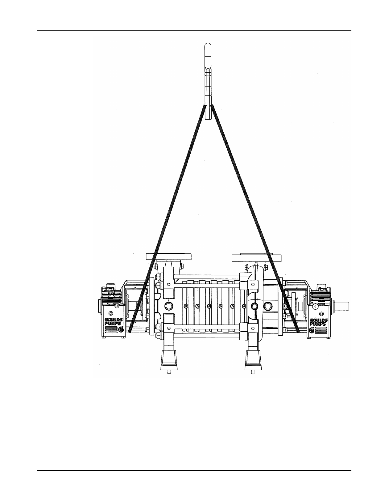
Transportation and Storage
Figure 1: Example of the proper lifting method for a bare pump
Baseplate-mounted units have lifting points for use with proper lifting devices.
Model 3393 Installation, Operation, and Maintenance Manual 11
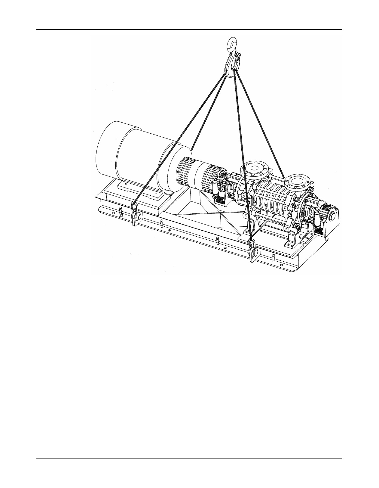
Transportation and Storage
Figure 2: Example of the proper lifting method for baseplate-mounted units
Storage guidelines
Long-term storage
If the unit is stored for more than 6 months, these requirements apply:
• Store in a covered and dry location.
• Store the unit free from heat, dirt, and vibrations.
• Rotate the shaft by hand several times at least every three months.
Treat bearing and machined surfaces so that they are well preserved. Refer to the drive unit
and coupling manufacturers for their long-term storage procedures.
For questions about possible long-term storage treatment services, please contact your local
ITT sales representative.
12 Model 3393 Installation, Operation, and Maintenance Manual
Product Description
General description
The Model 3393 is a radially split, segmented casing, multistage pump with these characteristics:
• Modular interstage components
• Varying numbers of stages, hydraulics, materials, and configurations
• Multiple suction nozzle and discharge nozzle orientations.
• Multiple hydraulics for each pump size
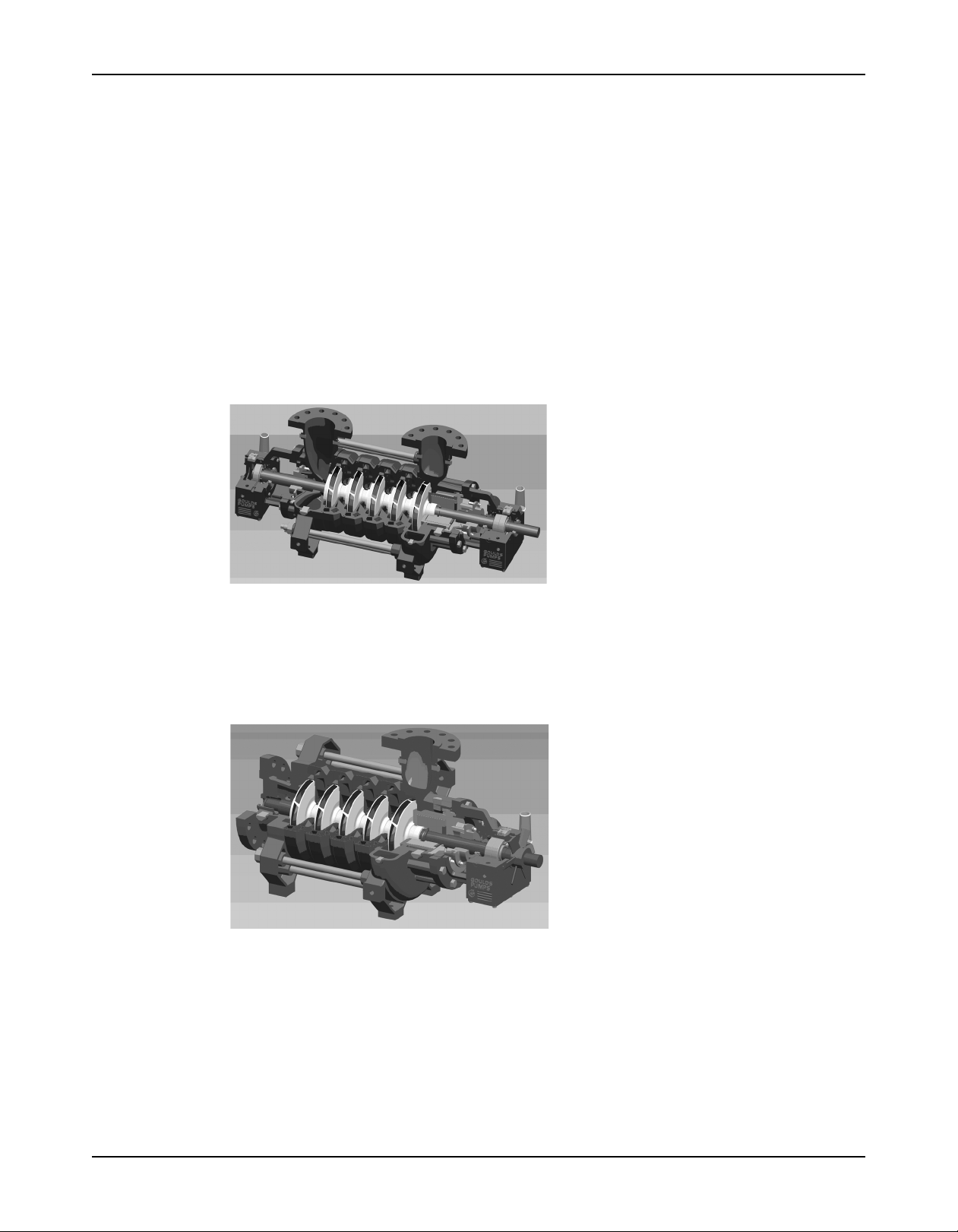
Radial suction configuration features radial suction and discharge nozzles. The suction and
discharge nozzles can be positioned either vertical or horizontally at 90º to either side. This
design consists of two robust, finned bearing housings with traditional anti-friction bearings and
mechanical seals on each end of the pump.
Product Description
Casing
Figure 3: Radial suction design
End suction configuration features an end suction nozzle in conjunction with a radial discharge
nozzle. The suction end of the pump utilizes a product-lubricated bearing eliminating the need
for a second bearing housing and mechanical seal. Because of the positioning of the sleeve
bearing in the end suction casing, the suction flange size is one size larger than the size for the
radial suction arrangement. The discharge nozzle can be positioned either vertically or
horizontally at 90º to either side.
Figure 4: End suction design
The pressure boundary consists of three basic casings and a mechanical seal chamber.
• The suction casing is available in an end or radial suction arrangement and is rated to a
lower pressure that the interstage or discharge casings.
• The interstage casings are combined with the diffuser into a single piece and are rated to
the full discharge pressure.
• The discharge casing is of dual volute construction.
Model 3393 Installation, Operation, and Maintenance Manual 13

Product Description
Flange ratings
Flange Options
Suction
ANSI B16.5 150 lb RF / ISO 7005-1 PN 20
ANSI B16.5 300 lb RF / ISO 7005-1 PN 50
EN 1092-1 PN 40
Discharge
EN 1092-1 PN 63
ANSI B16.5 600 lb RF / ISO 7005-1 PN 110
EN 1092-1 PN 100
ANSI B16.5 900 lb RF / ISO 7005-1 PN 150
(12 Chrome casing only)
Impeller
The impeller is a single suction, enclosed impeller. It is keyed to the shaft.
Seal chamber
The seal chamber accepts single or double cartridge seals and various piping plans. It is
dimensioned based on DIN 24960.
Bearing frame and bearings
The bearing frame is cast iron, finned for additional cooling and oil lubricated. Bearings are as
noted in the following table.
Pump Size 2.5x4-8 4x5-10 5x6-11 6x8-13
Bearing - driver end 7408 BCBM 7409 BCBM 7311 BECBM 7214 BECBM
(thrust)
Bearing - outboard SiC/SiC SiC/SiC SiC/SiC SiC/SiC
(ES) (radial)
Bearing - outboard 6408 6409 6311 6214
(RS) (radial)
Shaft
The shaft is of heavy-duty construction of 17-4 pH or super duplex depending on the casing
material. It is designed for cartridge mechanical seals to limit shaft deflection to .002 in. (0.051
mm) at worst case condition.
Baseplate
The baseplate is of fabricated steel and supports the pump, driver, and any accessories.
Pump description
The Goulds Model 3393 is a radially split, segmented casing, multistage pump designed with
modular interstage components. These identical components can be assembled to produce
pumps of varying numbers of stages, hydraulics, materials, and configurations to meet the
customer's specific requirements. Its multiple suction nozzle and discharge nozzle orientations
allow the 3393 to adapt to multiple piping installations and provide the piping designer with
flexibility in plant layout. Multiple hydraulics for each pump size optimize efficiency across a
vast range of applications. All intermediate stage components are identical which reduces
spare parts inventory.
The 3393 is designed as a two-pole speed pump. There will be times when the pump will be
operated at variable speed. The 3393 can be operated between 2700 and 3600 rpm without
reference to the factory. At speeds above 3600 rpm and below 2700 rpm, a lateral critical
speed analysis must be conducted by the factory. Contact your local representative for pricing.
In all cases it is imperative that the pump be brought up to its minimum operating speed as
quickly as possible. This ramp up time should not exceed 5 seconds.
14 Model 3393 Installation, Operation, and Maintenance Manual
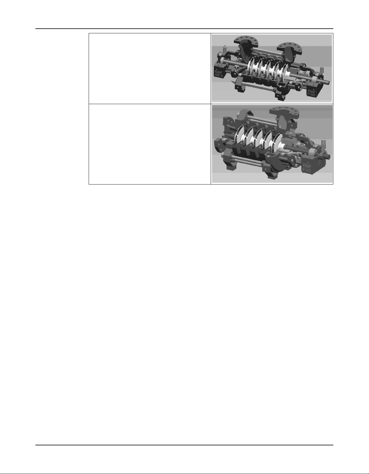
RS - Radial Suction configuration features radial
suction and discharge nozzles. The suction and
discharge nozzles can be positioned either vertically
or horizontally at 90Oto either side. This design
consists of two robust, finned bearing housings with
traditional anti-friction bearings and mechanical
seals on each end of the pump.
ES - End Suction configuration features an end
suction nozzle in conjunction with a radial discharge
nozzle. The suction end of the pump utilizes a
product-lubricated bearing eliminating the need for
a second bearing housing and mechanical seal.
Because of the positioning of the sleeve bearing in
the end suction casing, the suction flange size is
one size larger than the size for the radial suction
arrangement. The discharge nozzle can be positioned either vertically or horizontally at 90Oto either
side.
Product Description
General description i-ALERT™ Condition Monitor
Description
The i-ALERT Condition Monitor is a compact, battery-operated monitoring device that
continuously measures the vibration and temperature of the pump power end. The condition
monitor uses blinking red LEDs to alert the pump operator when the pump exceeds pre-set
vibration and temperature limits. This allows the pump operator to make changes to the
process or the pump before a catastrophic failure occurs. The condition monitor is also
equipped with a single green LED to indicate when it is operational and has sufficient battery
life.
Software License Agreement
BY USING THE i-Alert™ CONDITION MONITOR, YOU AGREE TO BE BOUND BY THE
TERMS AND CONDITIONS OF THE FOLLOWING LICENSE AGREEMENT. PLEASE READ
THIS AGREEMENT CAREFULLY.
ITT Corporation and its subsidiaries, affiliates, either directly, or through its authorized
sublicensees ("ITT") grants you a limited, non-exclusive license to use the software embedded
in this device ("Software") in binary executable form in the normal operation of the i-Alert™
condition monitor for monitoring the condition of an Goulds Pump Inc. model. Title, ownership
rights, and intellectual property rights in and to the Software remain in ITT or its third-party
providers. You agree that this license agreement does not need to be signed for it to take
effect.
You acknowledge that this Software is the property of ITT and is protected under United States
of America copyright laws and international copyright treaties. You further acknowledge that
the structure, organization, and code of the Software are valuable trade secrets of ITT and/or
its third-party providers and that the Software in source code form remains a valuable trade
secret of ITT. You agree not to decompile, disassemble, modify, reverse assemble, reverse
engineer, or reduce to human readable form the Software or any part thereof or create any
derivative works based on the Software. You agree not to export or re-export the Software to
any country in violation of the export control laws of the United States of America.
Model 3393 Installation, Operation, and Maintenance Manual 15

Product Description
Alarm mode
The condition monitor enters alarm mode when either vibration or temperature limits are
exceeded over two consecutive readings within a ten minute period. Alarm mode is indicated
with two red flashing LEDs within two second intervals.
Temperature and vibration limits
Variable Limit
Temperature 195°F (91°C)
Vibration 100% increase over the baseline level
Battery life
The i-ALERT Condition Monitor battery is not replaceable. You must replace the entire unit
once the battery runs out of power.
The battery life is not covered as part of the standard five-year pump warranty.
This table shows the average condition monitor battery life under normal and alarm-mode operating
conditions.
Condition monitor operational state Battery life
Normal operating and environmental conditions Three to five years
Alarm mode One year
Nameplate information
Important information for ordering
Every pump has a nameplate that provides information about the pump. The nameplate is
located on the pump casing.
When you order spare parts, identify this pump information:
• Model
• Size
• Serial number
• Item numbers of the required parts
Nameplate types
Nameplate Description
Pump casing Provides information about the hydraulic characteristics of the pump.
Bearing frame Provides information about the lubrication system used.
ATEX If applicable, your pump unit might have an ATEX nameplate affixed to the pump, the
IECEx If applicable, your pump unit might have the following IECEx nameplate affixed to the
Other If applicable, additional information, warnings or cautions may be noted.
The formula for the pump size is: Discharge x Suction - Nominal Maximum Impeller
Diameter in inches.
(Example: 2x3-8)
baseplate, or the discharge head. The nameplate provides information about the
ATEX specifications of this pump.
pump and/or baseplate. The nameplate provides information about the IECEx
specifications of this pump.
16 Model 3393 Installation, Operation, and Maintenance Manual
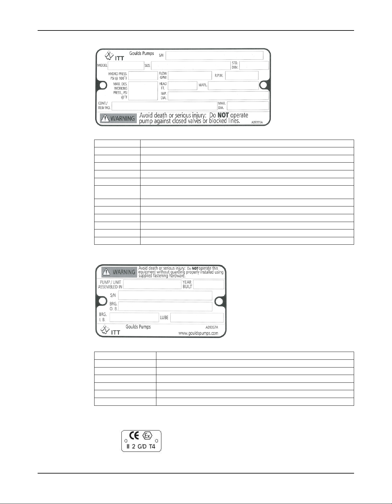
Nameplate on the pump casing using English units
Table 1: Explanation of nameplate on the pump casing
Nameplate field Explanation
S/N Goulds serial number
Model Pump model
Size Size of the pump
Std. Dim Standard Dimensional designation
Hydro Pressure Hydrostatic pressure at 70°F, in pounds per square inch
Max. Design Maximum working pressure in pounds per square inch
Working Press.
RPM Rated pump speed, in revolutions per minute
Head Rated pump head in feet
Material Pump material
Impeller Diameter Impeller trim diameter
Cont/Item No Purchaser's contract or item number
Max. Dia Impeller maximum diameter
Product Description
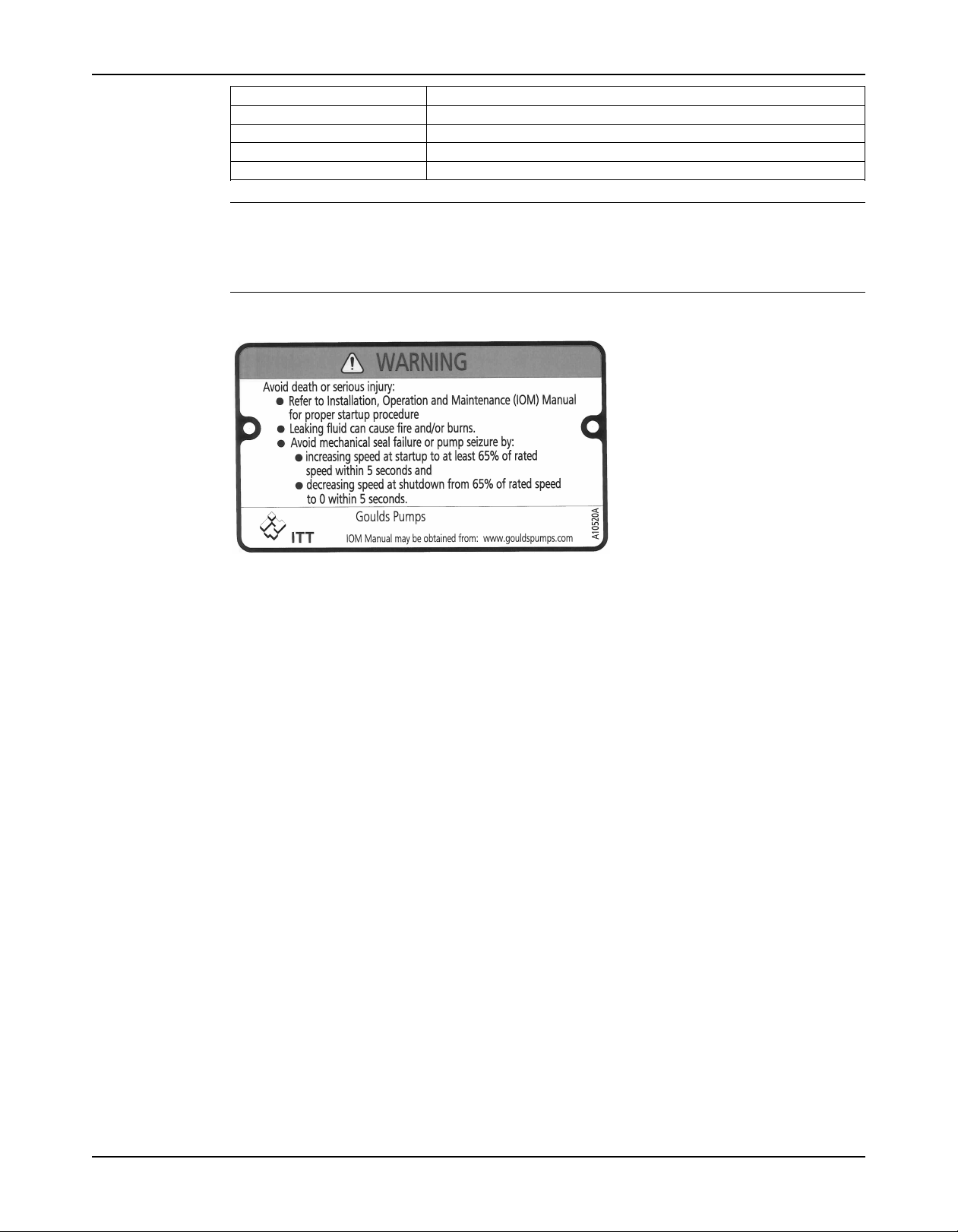
Nameplate on the bearing frame
Table 2: Explanation of the nameplate on the bearing frame
Nameplate field Explanation
Assembled in Country in which final unit built
Year built Year in which final unit built
S/N Serial number
Bearing O.B. Outboard bearing number/designation
Bearing I.B. Inboard bearing number/designation
Lubrication Type of lubrication of pump
ATEX nameplate
Model 3393 Installation, Operation, and Maintenance Manual 17
Product Description
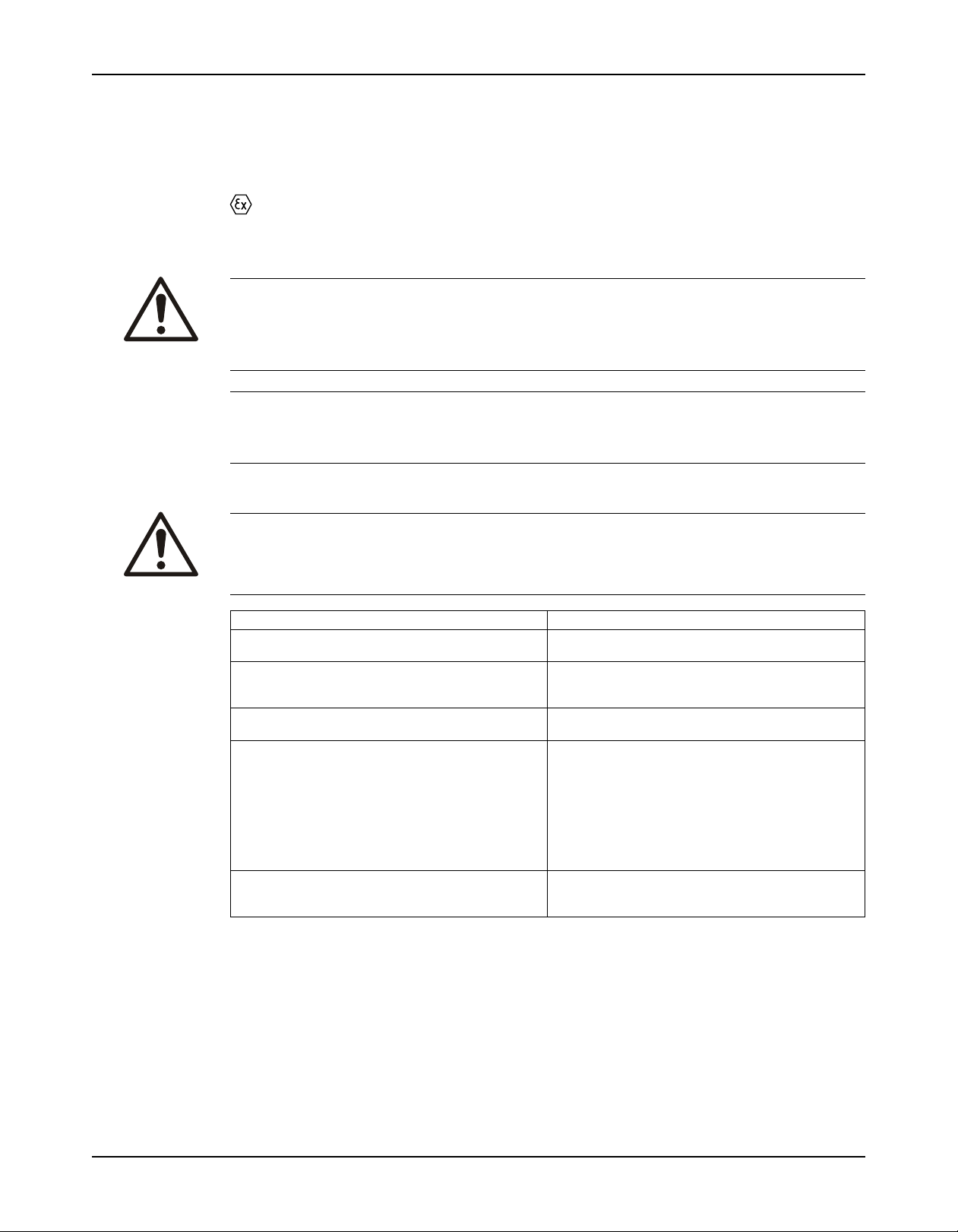
Warning nameplate
Nameplate field Explanation
II Group 2
2 Category 2
G/D Pump can be used when gas and dust are present
T4 Temperature class
NOTICE:
Make sure that the code classifications on the pump are compatible with the specific
environment in which you plan to install the equipment. If they are not compatible, do not
operate the equipment and contact your ITT representative before you proceed.
The nameplate shown is the standard warning and is applicable for most pumps. You must
refer to the startup procedures in the IOM for any specific instructions that may be different.
The instructions in the IOM will take precedence.
18 Model 3393 Installation, Operation, and Maintenance Manual
Installation
Preinstallation
Equipment that will operate in a potentially explosive environment must be installed in
accordance with the following instructions.
Precautions
WARNING:
• When installing in a potentially explosive environment, make sure that the motor is properly certified
and that all equipment is installed in accordance with appropriate instructions for that environment.
• You must earth (ground) all equipment. This applies to the pump equipment, the driver, and any
monitoring equipment. Test the earth (ground) lead to verify that it is connected correctly.
NOTICE:
Supervision by an authorized ITT representative is recommended to ensure proper installation.
Failure to do so may result in equipment damage or decreased performance.
Pump location guidelines
Installation
WARNING:
Assembled units and their components are heavy. Failure to properly lift and support this equipment can
result in serious physical injury and/or equipment damage. Lift equipment only at the specifically identified
lifting points. Lifting devices such as eyebolts, slings, and spreaders must be rated, selected, and used for
the entire load being lifted.
Guideline Explanation/comment
Make sure that the space around the pump is This facilitates ventilation, inspection, maintenance,
sufficient. and service.
If you require lifting equipment such as a hoist or This makes it easier to properly use the lifting
tackle, make sure that there is enough space above equipment and safely remove and relocate the
the pump. components to a safe location.
Protect the unit from weather and water damage This is applicable if nothing else is specified.
due to rain, flooding, and freezing temperatures.
Do not install and operate the equipment in closed Acceptable devices:
systems unless the system is constructed with
properly-sized safety devices and control devices.
Take into consideration the occurrence of unwanted The best pump location for noise and vibration
noise and vibration. absorption is on a concrete floor with subsoil
Foundation requirements
• Pressure relief valves
• Compression tanks
• Pressure controls
• Temperature controls
• Flow controls
If the system does not include these devices,
consult the engineer or architect in charge before
you operate the pump.
underneath.
Requirements
• The foundation must be able to absorb any type of vibration and form a permanent, rigid
support for the unit.
• Provide a flat, substantial concrete foundation in order to prevent strain and distortion
when you tighten the foundation bolts.
• Sleeve-type and J-type foundation bolts are most commonly used. Both designs allow
movement for the final bolt adjustment.
Model 3393 Installation, Operation, and Maintenance Manual 19
Installation
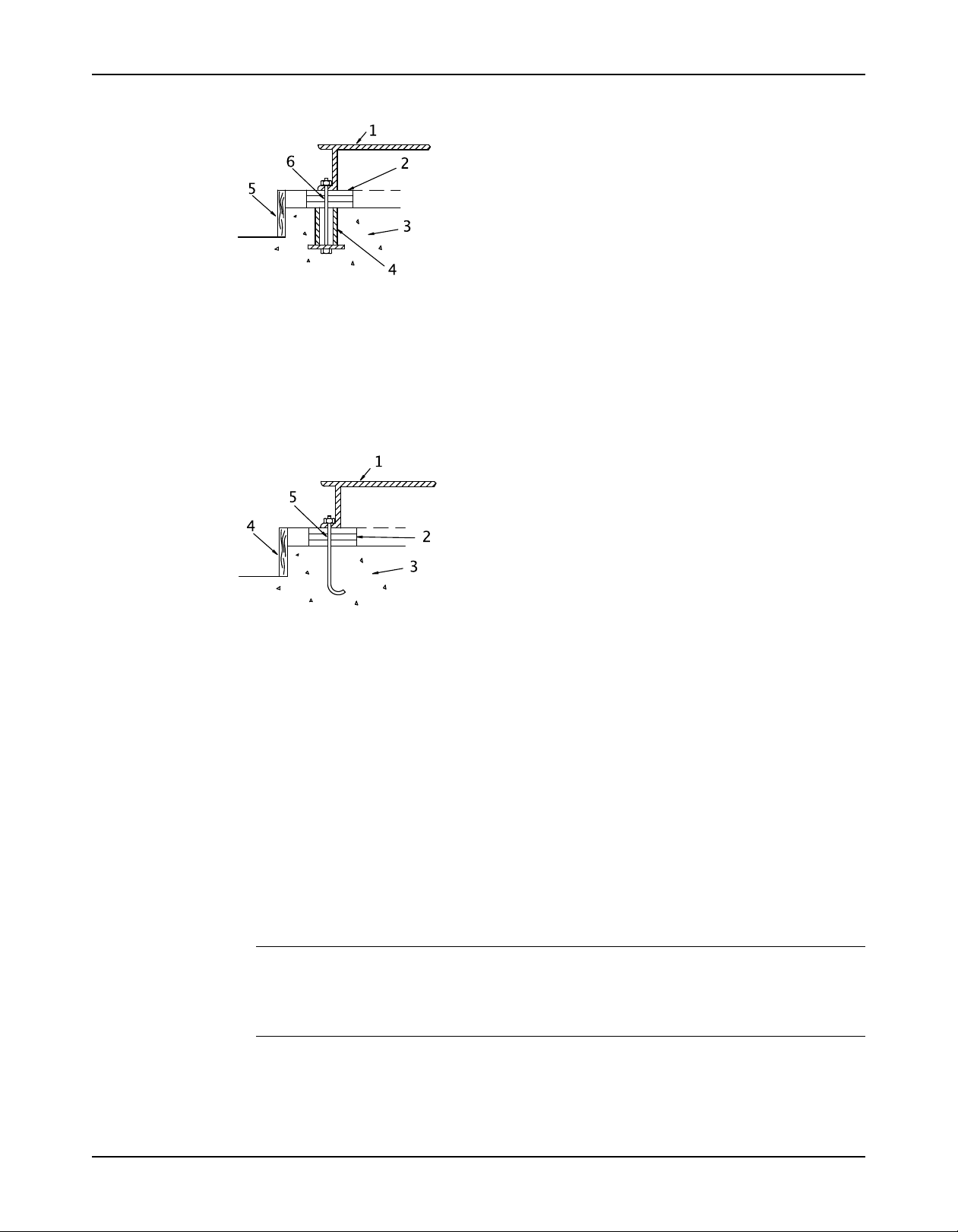
Sleeve-type bolts
J-type bolts
1. Baseplate
2. Shims or wedges
3. Foundation
4. Sleeve
5. Dam
6. Bolt
1. Baseplate
2. Shims or wedges
3. Foundation
4. Dam
5. Bolt
Baseplate-mounting procedures
Prepare the baseplate for mounting
This procedure assumes you have a basic knowledge of baseplate and foundation design and
installation methods. Follow industry-standard procedures, such as API RP 686/ PIP REIE 686,
or this procedure before you grout the baseplate.
1. Make sure that all baseplate surfaces that will contact grout are free from contamination
such as rust, oil, and grime.
2. Thoroughly clean all baseplate surfaces that will come in contact with grout.
Make sure to use a cleaner that will not leave residue.
NOTICE:
You may need to sandblast the surfaces of a baseplate that come in contact with grout, and
then coat those surfaces with a primer that is grout-compatible. Make sure to remove all
equipment before sandblasting.
3. Make sure that all machined surfaces are free from burrs, rust, paint, or any other type of
contamination.
If necessary, use a honing stone to remove burrs.
20 Model 3393 Installation, Operation, and Maintenance Manual
Prepare the foundation for mounting
1. Chip the top of the foundation to a minimum of 1.0 in. (25.0 mm) in order to remove porous
or low-strength concrete.
If you use a pneumatic hammer, make sure that it does not contaminate the surface with oil
or other moisture.
NOTICE:
Do not chip the foundation using heavy tools such as jackhammers. This can damage the
structural integrity of the foundation.
2. Remove water or debris from the foundation bolt holes or sleeves.
3. If the baseplate uses sleeve-type bolts, then fill the sleeves with a non-binding, moldable
material. Seal the sleeves in order to prevent the grout from entering.
4. Coat the exposed portion of the anchor bolts with a non-bonding compound such as paste
wax in order to prevent the grout from adhering to the anchor bolts.
Do not use oils or liquid wax.
5. If recommended by the grout manufacturer, coat the foundation surface with a compatible
primer.
Install and level the baseplate
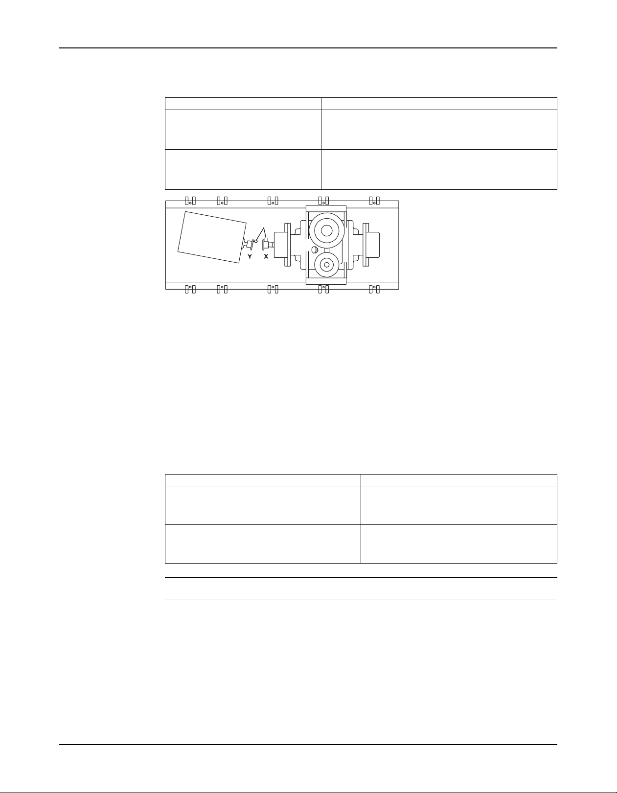
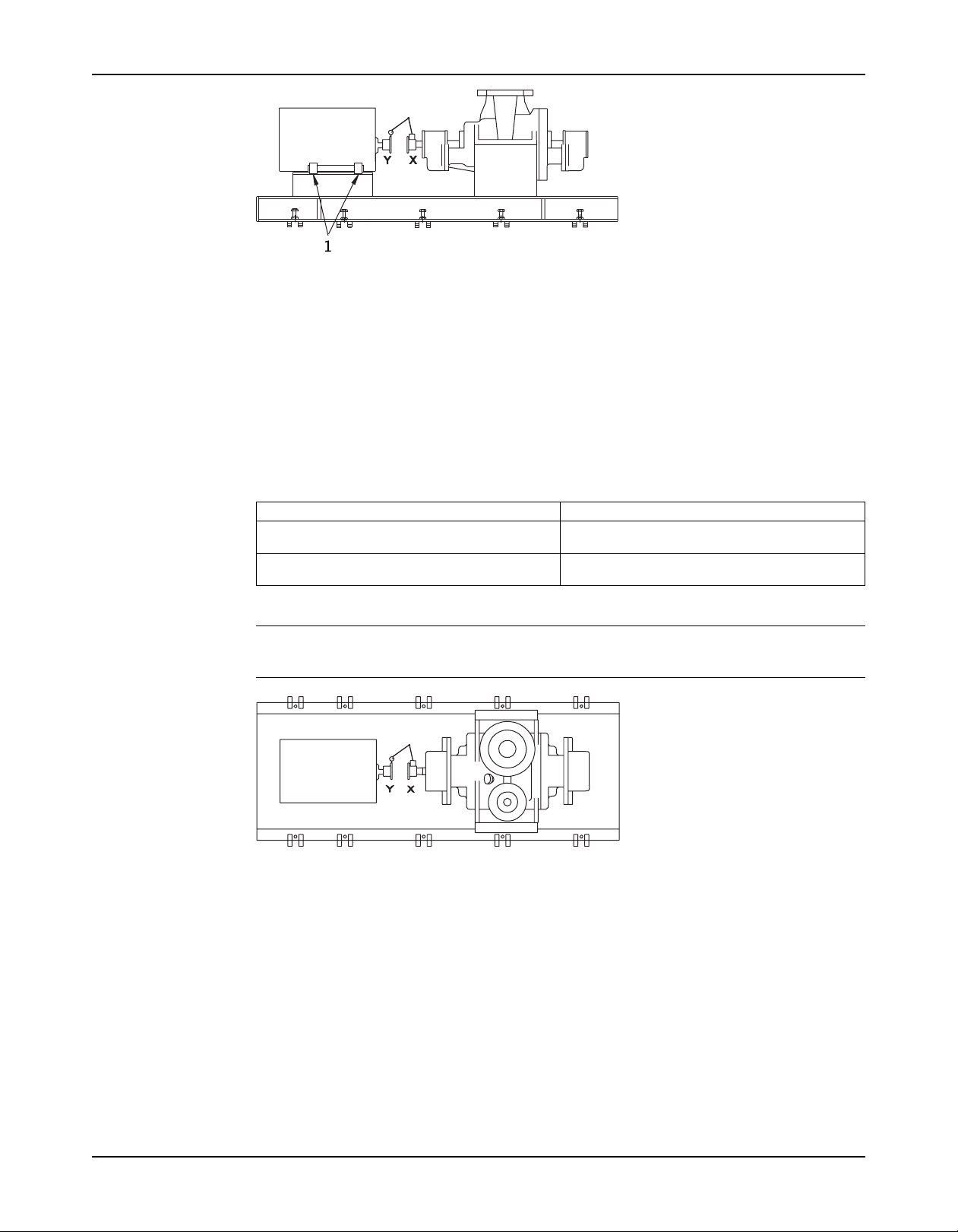
NOTICE:Illustrations are for reference only and may not depict the particular pump model.
Installation
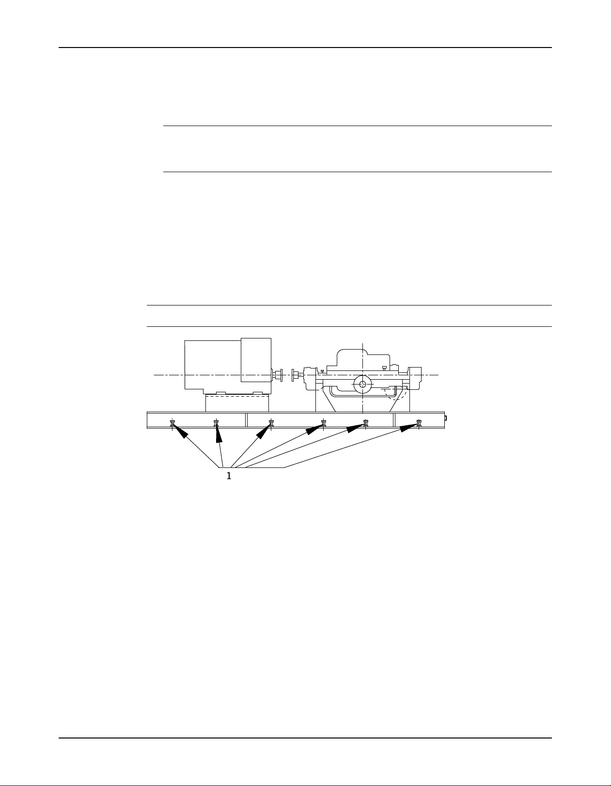
1. Jackscrews
Figure 5: Jackscrew locations, side view
1. Jackscrews
Figure 6: Jackscrew locations, top view
1. Lower the baseplate carefully onto the foundation bolts.
The baseplate will rest on top of the foundation on the jackscrews provided on the
baseplate.
2. Adjust the leveling jackscrews, located adjacent to the foundation bolt holes, until the
baseplate rests 1 to 2 in. (25 to 50 mm) above the foundation in order to allow for adequate
grouting.
This provides even support for the baseplate after grouting.
3. Level the baseplate to within 0.002 in./ft. (0.167 mm/m) of the length or width of the
baseplate by adjusting the jackscrews.
• The maximum total variation from one end or side of the baseplate to the other is
0.015 in. (0.38 mm).
• Use the equipment mounting surfaces in order to establish the level.
4. Use a non-bonding (anti-seize) compound such as paste wax to coat the portions of the
jackscrews that will contact the grout.
Model 3393 Installation, Operation, and Maintenance Manual 21

Installation
This facilitates removal of the screws after grouting.
NOTICE:
Do not use oils or liquid wax.
5. Thread the nuts onto the foundation bolts and hand-tighten.
Install the pump, driver and coupling
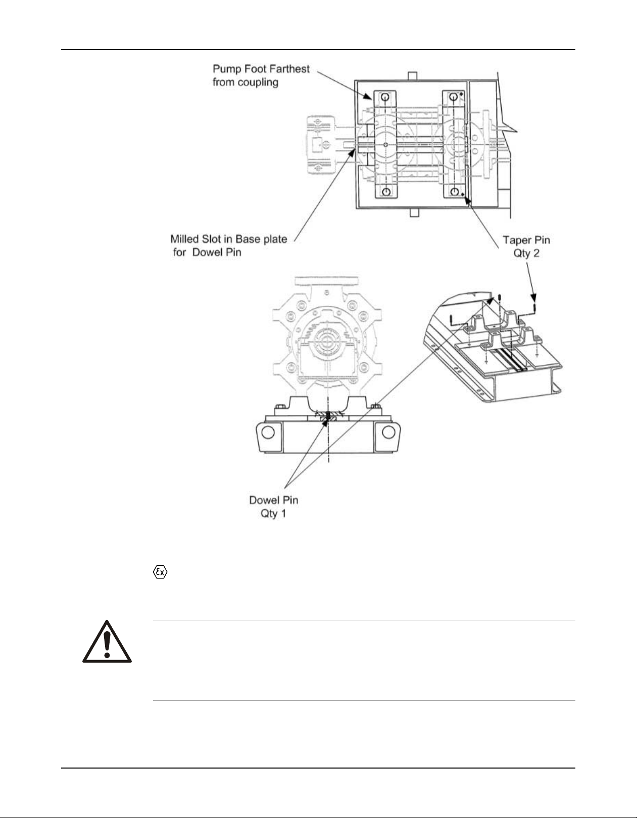
1. Mount and fasten the pump on the baseplate. Use applicable bolts.
NOTICE:Two tapered dowel pins are provided in case there is a need to provide
repeatable location between the pump and base plate. Installation of the dowel pins is not
mandatory.
2. Mount the driver on the baseplate.
3. Install the coupling. See the installation instructions from the coupling manufacturer.
4. If the pump baseplate has a slot for high temperature dowelling the following must be
performed after final alignment.
a) Verify that the parallel dowel has been installed in the center of the pump foot furthest
from the drive end. It should locate fully in a slot parallel to the shaft that has been
machined in the base plate.
b) Torque the bolts closest to the driver to the standard values.
c) Torque the bolts on the outboard end to 15% of the standard value. This will allow the
pump to expand axially with increasing temperature while maintaining pump to driver
alignment.
5. If repeatable location of the pump to base plate is desired perform either 5.a. or 5.b.
a) For pumps without high temperature doweling, drill through each pump foot (drive end
and non drive end), into the base plate then taper ream to suit the supplied taper dowel
pins.
b) For pumps fitted with high temperature doweling, drill through the drive end pump foot
into the base plate then taper ream to suit the supplied taper dowel pin. Discard the
unused taper dowel pin.
22 Model 3393 Installation, Operation, and Maintenance Manual
Installation
Pump-to-driver alignment
Alignment procedures must be followed to prevent unintended contact of rotating parts.
Follow coupling manufacturer's installation and operation procedures.
Precautions
WARNING:
• Follow shaft alignment procedures in order to prevent catastrophic failure of drive components or
unintended contact of rotating parts. Follow the coupling installation and operation procedures from
the coupling manufacturer.
• Always disconnect and lock out power to the driver before you perform any installation or
maintenance tasks. Failure to disconnect and lock out driver power will result in serious physical
injury.
Model 3393 Installation, Operation, and Maintenance Manual 23

Installation
NOTICE:
Proper alignment is the responsibility of the installer and the user of the unit. Check the
alignment of frame-mounted units before you operate the unit. Failure to do so can result in
equipment damage or decreased performance.
Alignment methods
Three common alignment methods are used:
• Dial indicator
• Reverse dial indicator
• Laser
Follow the instructions from the equipment manufacturer when you use the reverse dial
indicator or laser methods. Detailed instructions for using the dial indicator method are
contained in this chapter.
Alignment checks
When to perform alignment checks
You must perform alignment checks under these circumstances:
• The process temperature changes.
• The piping changes.
• The pump has been serviced.
Types of alignment checks
Type of check When it is used
Initial alignment (cold alignment) Prior to operation when the pump and the driver are at ambient
check temperature.
Final alignment (hot alignment) After operation when the pump and the driver are at operating
check temperature.
Initial alignment (cold alignment) checks
When Why
Before you grout the baseplate This ensures that alignment can be accomplished.
After you grout the baseplate This ensures that no changes have occurred during the grouting
After you connect the piping This ensures that pipe strains have not altered the alignment.
process.
If changes have occurred, you must alter the piping to remove pipe
strains on the pump flanges.
Final alignment (hot alignment) checks
When Why
After the first run This ensures correct alignment when both the pump and the driver
Periodically This follows the plant operating procedures.
are at operating temperature.
Permitted indicator values for alignment checks
NOTICE:
The specified permitted reading values shown in the tables are valid only for motors with the
temperature rise noted. For other drivers such as steam turbines, engines or motors with a
different temperature rise, the correct settings must be recalculated. If the pump is driven
through a speed reduction or speed increasing gear, contact the factory. You must use the
correct tolerances. Failure to do so can result in misalignment and reduced pump reliability.
Alignment Criteria: Cold parallel vertical alignment setting
24 Model 3393 Installation, Operation, and Maintenance Manual

Installation
NOTICE:A positive value indicates that the pump shaft should be set higher than the motor
shaft; a negative value indicates that the pump shaft should be set lower than the motor shaft.
Table 3: Pump operating temperature for 2.5x4-8 and 2.5x5-8
Motor Temperature English units (inches) Metric units (mm)
Rise
<100oF 100- 201- 301-400oF <38oC 38-93oC 94- 150-
104oF (40oC) 0.004 0.000 -0.009 -0.018 0.11 0.00 -0.23 -0.46
122oF (50oC) 0.006 0.001 -0.007 -0.017 0.15 0.04 -0.19 -0.42
Table 4: Pump operating temperature for 4x5-10 and 4x6-10
Motor Temperature English units (inches) Metric units (mm)
Rise
<100oF 100- 201- 301- <38oC 38- 94-149oC 150-
104oF (40oC) 0.005 0.000 -0.010 -0.021 0.13 0.00 -0.26 -0.53
122oF (50oC) 0.007 0.002 -0.009 -0.019 0.17 0.04 -0.22 -0.48
Table 5: Pump operating temperature for 5x6-11 and 5x8-11
Motor Temperature English units (inches) Metric units (mm)
Rise
<100oF 100- 201- 301-400oF <38oC 38-93oC 94- 150-
104oF (40oC) 0.006 0.000 -0.012 -0.023 0.14 -0.01 -0.30 -0.59
122oF (50oC) 0.008 0.002 -0.010 -0.021 0.20 0.05 -0.24 -0.54
200oF 300oF 149oC 204oC
200oF 300oF 400oF 93oC 204oC
200oF 300oF 149oC 204oC
Table 6: Pump operating temperature for 6x8-13 and 6x10-13
Motor Temperature English units (inches) Metric units (mm)
Rise
<100oF 100- 201- 301- <38oC 38- 94-149oC 150-
104oF (40oC) 0.006 0.000 -0.013 -0.027 0.16 -0.01 -0.34 -0.68
122oF (50oC) 0.009 0.002 -0.011 -0.024 0.22 0.05 -0.28 -0.62
200oF 300oF 400oF 93oC 204oC
Alignment measurement guidelines
Guideline Explanation
Rotate the pump coupling half and the driver This prevents incorrect measurement.
coupling half together so that the indicator rods
have contact with the same points on the driver
coupling half.
Move or shim only the driver in order to make This prevents strain on the piping installations.
adjustments.
Make sure that the hold-down bolts for the driver This keeps the driver stationary since movement
feet are tight when you take indicator measure- causes incorrect measurement.
ments.
Make sure that the hold-down bolts for the driver This makes it possible to move the driver when you
feet are loose before you make alignment correc- make alignment corrections.
tions.
Check the alignment again after any mechanical This corrects any misalignments that an adjustment
adjustments. may have caused.
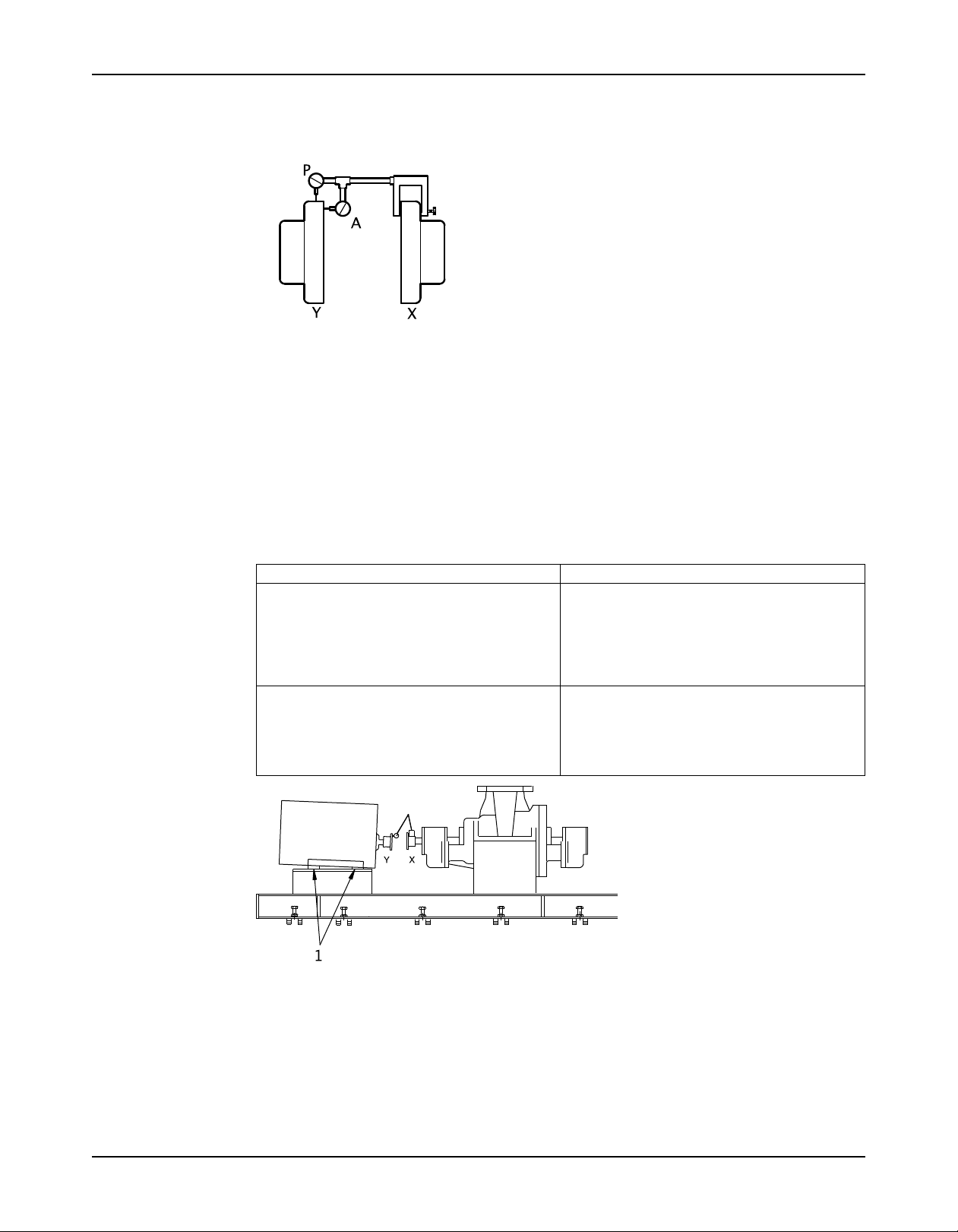
Attach the dial indicators for alignment
You must have two dial indicators in order to complete this procedure.
1. Attach two dial indicators on the pump coupling half (X):
a) Attach one indicator (P) so that the indicator rod comes into contact with the perimeter
of the driver coupling half (Y).
This indicator is used to measure parallel misalignment.
Model 3393 Installation, Operation, and Maintenance Manual 25
Installation
b) Attach the other indicator (A) so that the indicator rod comes into contact with the inner
end of the driver coupling half.
This indicator is used to measure angular misalignment.
2. Rotate the pump coupling half (X) in order to check that the indicators are in contact with
the driver coupling half (Y) but do not bottom out.
3. Adjust the indicators if necessary.
Perform angular alignment for a vertical correction
Illustrations are for reference only and may not depict the particular pump model.
1. Set the angular alignment indicator to zero at the top-center position (12 o’clock) of the
driver coupling half (Y).
2. Rotate the indicator to the bottom-center position (6 o’clock).
3. Record the indicator reading.
When the reading value is... Then...
Negative The coupling halves are farther apart at the
Positive The coupling halves are closer at the bottom than
bottom than at the top. Perform one of these
steps:
• Add shims in order to raise the feet of the
driver at the shaft end.
• Remove shims in order to lower the feet of the
driver at the other end.
at the top. Perform one of these steps:
• Remove shims in order to lower the feet of the
driver at the shaft end.
• Add shims in order to raise the feet of the
driver at the other end.
1. Shims
Figure 7: Example of incorrect vertical alignment (side view)
4. Repeat the previous steps until the permitted reading value is achieved.
Perform angular alignment for a horizontal correction
1. Set the angular alignment indicator (A) to zero on left side of the driver coupling half (Y),
90° from the top-center position (9 o’clock).
26 Model 3393 Installation, Operation, and Maintenance Manual
Installation
2. Rotate the indicator through the top-center position to the right side, 180° from the start
position (3 o’clock).
3. Record the indicator reading.
When the reading value is... Then...
Negative The coupling halves are farther apart on the right side than
Positive The coupling halves are closer together on the right side
Figure 8: Example of incorrect horizontal alignment (top view)
the left. Perform one of these steps:
• Slide the shaft end of the driver to the left.
• Slide the opposite end to the right.
than the left. Perform one of these steps:
• Slide the shaft end of the driver to the right.
• Slide the opposite end to the left.
4. Repeat the previous steps until the permitted reading value is achieved.
Perform parallel alignment for a vertical correction
Refer to the alignment table in "Permitted indicator values for alignment checks" (see Table of
Contents for location of table) for the proper cold alignment value based on the motor
temperature rise and the pump operating temperature.
Before you start this procedure, make sure that the dial indicators are correctly set up.
A unit is in parallel alignment when the parallel indicator (P) does not vary by more than
0.002 in. (0.05 mm) as measured at four points 90° apart at the operating temperature.
1. Set the parallel alignment indicator (P) to zero at the top-center position (12 o’clock) of the
driver coupling half (Y).
2. Rotate the indicator to the bottom-center position (6 o’clock).
3. Record the indicator reading.
When the reading value is... Then...
Negative The pump coupling half (X) is lower than the
Positive The pump coupling half (X) is higher than the
NOTICE:
driver coupling half (Y). Remove shims of a
thickness equal to half of the indicator reading
value under each driver foot.
driver coupling half (Y). Add shims of a thickness
equal to half of the indicator reading value to each
driver foot.
Model 3393 Installation, Operation, and Maintenance Manual 27
Installation
1. Shims
Figure 9: Example of incorrect vertical alignment (side view)
4. Repeat the previous steps until the permitted reading value is achieved.
Perform parallel alignment for a horizontal correction
A unit is in parallel alignment when the parallel indicator (P) does not vary by more than
0.002 in. (0.05 mm) as measured at four points 90° apart at the operating temperature.
1. Set the parallel alignment indicator (P) to zero on the left side of the driver coupling half (Y),
90° from the top-center position (9 o’clock).
2. Rotate the indicator through the top-center position to the right side, 180° from the start
position (3 o’clock).
3. Record the indicator reading.
When the reading value is... Then...
Negative The driver coupling half (Y) is to the left of the
Positive The driver coupling half (Y) is to the right of the
pump coupling half (X).
pump coupling half (X).
4. Slide the driver carefully in the appropriate direction.
NOTICE:Make sure to slide the driver evenly. Failure to do so can negatively affect
horizontal angular correction.
Figure 10: Example of incorrect horizontal alignment (top view)
5. Repeat the previous steps until the permitted reading value is achieved.
Perform complete alignment for a vertical correction
A unit is in complete alignment when both the angular indicator (A) and the parallel indicator (P)
do not vary by more than 0.002 in. (0.05 mm) as measured at four points 90° apart.
1. Set the angular and parallel dial indicators to zero at the top-center position (12 o’clock) of
the driver coupling half (Y).
2. Rotate the indicators to the bottom-center position (6 o’clock).
3. Record the indicator readings.
4. Make corrections according to the separate instructions for angular and parallel alignment
until you obtain the permitted reading values.
28 Model 3393 Installation, Operation, and Maintenance Manual
 Loading...