

Page 1
Installation, Operation,
and Maintenance Manual
Model 3355
Page 2

Page 3

Table of Contents
Introduction and Safety .......................................................................................................... 3
Introduction ............................................................................................................................. 3
Safety ...................................................................................................................................... 3
Safety terminology and symbols ........................................................................................... 3
Environmental safety ............................................................................................................ 4
User safety ........................................................................................................................... 5
Ex-approved products .......................................................................................................... 5
Product warranty ..................................................................................................................... 6
Transportation and Storage ................................................................................................... 8
Inspect the delivery ................................................................................................................. 8
Inspect the package ............................................................................................................. 8
Inspect the unit ..................................................................................................................... 8
Transportation guidelines ........................................................................................................ 8
Pump handling and lifting ..................................................................................................... 8
Storage guidelines .................................................................................................................. 9
Pump storage requirements ................................................................................................. 9
Product Description .............................................................................................................. 10
General description ............................................................................................................... 10
Part description .................................................................................................................. 11
Nameplate information .......................................................................................................... 12
Table of Contents
Installation ............................................................................................................................. 14
Preinstallation ....................................................................................................................... 14
Pump location guidelines .................................................................................................... 14
Foundation requirements ................................................................................................... 14
Baseplate-mounting procedures ........................................................................................... 15
Prepare the baseplate for mounting ................................................................................... 15
Install the baseplate using shims or wedges ...................................................................... 15
Pump-to-driver alignment ...................................................................................................... 16
Alignment checks ............................................................................................................... 16
Permitted indicator values for alignment checks ................................................................ 17
Alignment measurement guidelines ................................................................................... 17
Attach the dial indicators for alignment ............................................................................... 17
Pump-to-driver alignment instructions ................................................................................ 18
Grout the baseplate .............................................................................................................. 19
Piping checklists ................................................................................................................... 20
General piping checklist ..................................................................................................... 21
Suction-piping checklist ...................................................................................................... 22
Discharge piping checklist .................................................................................................. 23
Final piping checklist .......................................................................................................... 23
Commissioning, Startup, Operation, and Shutdown ......................................................... 25
Preparation for startup .......................................................................................................... 25
Remove the coupling guard .................................................................................................. 26
Check the rotation - Frame Mounted ..................................................................................... 26
Couple the pump and driver .................................................................................................. 27
Install the coupling guard .................................................................................................... 27
Pump priming ........................................................................................................................ 29
Prime the pump with the suction supply above the pump ................................................... 29
Prime the pump with the suction supply below the pump ................................................... 29
Other methods of priming the pump ................................................................................... 30
Model 3355 Installation, Operation, and Maintenance Manual 1
Page 4

Table of Contents
Start the pump ...................................................................................................................... 30
Pump operation precautions ................................................................................................. 31
Shut down the pump ............................................................................................................. 31
Make the final alignment of the pump and driver ................................................................... 32
Maintenance ........................................................................................................................... 33
Maintenance schedule .......................................................................................................... 33
Bearing maintenance ............................................................................................................ 34
Ball bearing types ............................................................................................................... 34
Grease lubrication schedule ............................................................................................... 34
Lubricating-grease requirements ........................................................................................ 34
Regrease the grease-lubricated bearings .......................................................................... 34
Lubricate the bearings after a shutdown period .................................................................. 35
Shaft-seal maintenance ........................................................................................................ 35
Mechanical-seal maintenance ............................................................................................ 35
Disassembly ......................................................................................................................... 36
Disassembly precautions ................................................................................................... 36
Tools required .................................................................................................................... 36
Drain the pump ................................................................................................................... 37
Prepare for disassembly ..................................................................................................... 37
Disassemble the discharge end ball bearing for the radial suction configuration ................ 37
Disassemble the pump body .............................................................................................. 38
Disassemble the suction end ball bearings ........................................................................ 38
Remove the shaft seal ........................................................................................................ 38
Preassembly inspections ...................................................................................................... 39
Replacement guidelines ..................................................................................................... 39
Reassembly .......................................................................................................................... 39
Prepare for reassembly ...................................................................................................... 39
Reassemble the shaft seal ................................................................................................. 39
Reassemble the suction end ball bearings ......................................................................... 40
Reassemble the pump body ............................................................................................... 41
Complete the reassembly for the end suction configuration ............................................... 41
Reassemble the discharge end ball bearings for the radial suction configuration .............. 42
Assembly references ............................................................................................................ 43
Torque values ..................................................................................................................... 43
Gap widths ......................................................................................................................... 43
Nozzle loads ....................................................................................................................... 44
Recommended minimum flows .......................................................................................... 46
Wearing parts and dimensions ........................................................................................... 46
Troubleshooting .................................................................................................................... 48
Alignment troubleshooting .................................................................................................... 48
Operation troubleshooting ..................................................................................................... 48
Parts Listings and Cross-sectional Drawings .................................................................... 53
Recommended spare parts ................................................................................................... 53
Radial suction all-iron cross-sectional ................................................................................... 54
Radial suction all iron with stainless steel impeller cross sectional ....................................... 55
Radial suction stainless steel cross-sectional ....................................................................... 56
End-suction all-iron cross-sectional ...................................................................................... 57
End-suction all-iron with stainless steel impeller cross-sectional .......................................... 58
End-suction stainless steel cross-sectional ........................................................................... 59
Radial suction (counterclockwise rotation) all-iron cross-sectional ....................................... 60
Radial suction (counterclockwise rotation) all-iron with stainless steel impeller cross-
sectional ................................................................................................................................ 61
Radial suction (counterclockwise rotation) stainless steel cross-sectional ........................... 62
2 Model 3355 Installation, Operation, and Maintenance Manual
Page 5
Introduction and Safety
Introduction
Purpose of this manual
The purpose of this manual is to provide necessary information for:
• Installation
• Operation
• Maintenance
CAUTION:
Read this manual carefully before installing and using the product. Improper use of the product can
cause personal injury and damage to property, and may void the warranty.
NOTICE:
Save this manual for future reference, and keep it readily available at the location of the unit.
Introduction and Safety
Requesting other information
Special versions can be supplied with supplementary instruction leaflets. See the sales
contract for any modifications or special version characteristics. For instructions, situations, or
events that are not considered in this manual or in the sales documents, please contact the
nearest ITT representative.
Always specify the exact product type and identification code when requesting technical
information or spare parts.
Safety
WARNING:
• The operator must be aware of safety precautions to prevent physical injury.
• Any pressure-containing device can explode, rupture, or discharge its contents if it is overpressurized. Take all necessary measures to avoid over-pressurization.
• Operating, installing, or maintaining the unit in any way that is not covered in this manual could
cause death, serious personal injury, or damage to the equipment. This includes any modification to
the equipment or use of parts not provided by ITT. If there is a question regarding the intended use of
the equipment, please contact an ITT representative before proceeding.
• Do not change the service application without the approval of an authorized ITT representative.
• Never operate the pump without safety devices installed.
• Never operate the pump with the discharge valve closed.
Safety terminology and symbols
About safety messages
It is extremely important that you read, understand, and follow the safety messages and
regulations carefully before handling the product. They are published to help prevent these
hazards:
• Personal accidents and health problems
• Damage to the product
• Product malfunction
Model 3355 Installation, Operation, and Maintenance Manual 3
Page 6
Introduction and Safety
Hazard levels
Hazard level Indication
A hazardous situation which, if not avoided, will
DANGER: result in death or serious injury
Hazard categories
WARNING: result in death or serious injury
CAUTION: result in minor or moderate injury
NOTICE:
A hazardous situation which, if not avoided, could
A hazardous situation which, if not avoided, could
• A potential situation which, if not avoided,
could result in undesirable conditions
• A practice not related to personal injury
Hazard categories can either fall under hazard levels or let specific symbols replace the
ordinary hazard level symbols.
Electrical hazards are indicated by the following specific symbol:
Electrical Hazard:
These are examples of other categories that can occur. They fall under the ordinary hazard
levels and may use complementing symbols:
• Crush hazard
• Cutting hazard
• Arc flash hazard
The Ex symbol
The Ex symbol indicates safety regulations for Ex-approved products when used in
atmospheres that are potentially explosive or flammable.
Environmental safety
The work area
Always keep the station clean to avoid and/or discover emissions.
Waste and emissions regulations
Observe these safety regulations regarding waste and emissions:
• Appropriately dispose of all waste.
• Handle and dispose of the processed liquid in compliance with applicable environmental
regulations.
• Clean up all spills in accordance with safety and environmental procedures.
• Report all environmental emissions to the appropriate authorities.
4 Model 3355 Installation, Operation, and Maintenance Manual
Page 7
WARNING:
Do NOT send the product to the ITT manufacturer if it has been contaminated by any nuclear radiation.
Inform ITT so that accurate actions can take place.
Electrical installation
For electrical installation recycling requirements, consult your local electric utility.
User safety
General safety rules
These safety rules apply:
Safety equipment
Use safety equipment according to the company regulations. Use this safety equipment within
the work area:
Introduction and Safety
• Always keep the work area clean.
• Pay attention to the risks presented by gas and vapors in the work area.
• Avoid all electrical dangers. Pay attention to the risks of electric shock or arc flash hazards.
• Always bear in mind the risk of drowning, electrical accidents, and burn injuries.
• Helmet
• Safety goggles, preferably with side shields
• Protective shoes
• Protective gloves
• Gas mask
• Hearing protection
• First-aid kit
• Safety devices
NOTICE:
Never operate a unit unless safety devices are installed. Also see specific information
about safety devices in other chapters of this manual.
Electrical connections
Electrical connections must be made by certified electricians in compliance with all international, national, state, and local regulations. For more information about requirements, see sections
dealing specifically with electrical connections.
Wash the skin and eyes
1. Follow these procedures for chemicals or hazardous fluids that have come into contact with
your eyes or your skin:
Condition Action
Chemicals or hazardous
fluids in eyes
Chemicals or hazardous
fluids on skin
1. Hold your eyelids apart forcibly with your fingers.
2. Rinse the eyes with eyewash or running water for at least
15 minutes.
3. Seek medical attention.
1. Remove contaminated clothing.
2. Wash the skin with soap and water for at least 1 minute.
3. Seek medical attention, if necessary.
Ex-approved products
Follow these special handling instructions if you have an Ex-approved unit.
Model 3355 Installation, Operation, and Maintenance Manual 5
Page 8

Introduction and Safety
Personnel requirements
These are the personnel requirements for Ex-approved products in potentially explosive
atmospheres:
• All work on the product must be carried out by certified electricians and ITT-authorized
mechanics. Special rules apply to installations in explosive atmospheres.
• All users must know about the risks of electric current and the chemical and physical
characteristics of the gas, the vapor, or both present in hazardous areas.
• Any maintenance for Ex-approved products must conform to international and national
standards (for example, IEC/EN 60079-17).
ITT disclaims all responsibility for work done by untrained and unauthorized personnel.
Product and product handling requirements
These are the product and product handling requirements for Ex-approved products in
potentially explosive atmospheres:
• Only use the product in accordance with the approved motor data.
• The Ex-approved product must never run dry during normal operation. Dry running during
service and inspection is only permitted outside the classified area.
• Before you start work on the product, make sure that the product and the control panel are
isolated from the power supply and the control circuit, so they cannot be energized.
• Do not open the product while it is energized or in an explosive gas atmosphere.
• Make sure that thermal contacts are connected to a protection circuit according to the
approval classification of the product, and that they are in use.
• Intrinsically safe circuits are normally required for the automatic level-control system by the
level regulator if mounted in zone 0.
• The yield stress of fasteners must be in accordance with the approval drawing and the
product specification.
• Do not modify the equipment without approval from an authorized ITT representative.
• Only use parts that are provided by an authorized ITT representative.
Description of ATEX
The ATEX directives are a specification enforced in Europe for electrical and non-electrical
equipment installed in Europe. ATEX deals with the control of potentially explosive atmospheres and the standards of equipment and protective systems used within these atmospheres. The relevance of the ATEX requirements is not limited to Europe. You can apply these
guidelines to equipment installed in any potentially explosive atmosphere.
Guidelines for compliance
Compliance is fulfilled only when you operate the unit within its intended use. Do not change
the conditions of the service without the approval of an ITT representative. When you install or
maintain explosion proof products, always comply with the directive and applicable standards
(for example, IEC/EN 60079–14).
Product warranty
Coverage
ITT undertakes to remedy faults in products from ITT under these conditions:
• The faults are due to defects in design, materials, or workmanship.
• The faults are reported to an ITT representative within the warranty period.
• The product is used only under the conditions described in this manual.
• The monitoring equipment incorporated in the product is correctly connected and in use.
• All service and repair work is done by ITT-authorized personnel.
6 Model 3355 Installation, Operation, and Maintenance Manual
Page 9

Limitations
Warranty claim
Introduction and Safety
• Genuine ITT parts are used.
• Only Ex-approved spare parts and accessories authorized by ITT are used in Ex-approved
products.
The warranty does not cover faults caused by these situations:
• Deficient maintenance
• Improper installation
• Modifications or changes to the product and installation made without consulting ITT
• Incorrectly executed repair work
• Normal wear and tear
ITT assumes no liability for these situations:
• Bodily injuries
• Material damages
• Economic losses
ITT products are high-quality products with expected reliable operation and long life. However,
should the need arise for a warranty claim, then contact your ITT representative.
Model 3355 Installation, Operation, and Maintenance Manual 7
Page 10
Transportation and Storage
Transportation and Storage
Inspect the delivery
Inspect the package
1. Inspect the package for damaged or missing items upon delivery.
2. Note any damaged or missing items on the receipt and freight bill.
3. File a claim with the shipping company if anything is out of order.
If the product has been picked up at a distributor, make a claim directly to the distributor.
Inspect the unit
1. Remove packing materials from the product.
Dispose of all packing materials in accordance with local regulations.
2. Inspect the product to determine if any parts have been damaged or are missing.
3. If applicable, unfasten the product by removing any screws, bolts, or straps.
For your personal safety, be careful when you handle nails and straps.
4. Contact your sales representative if anything is out of order.
Transportation guidelines
Precautions
WARNING:
• Stay clear of suspended loads.
• Observe accident prevention regulations in force.
Pump handling and lifting
Precautions for moving the pump
Use care when moving pumps. Consult with a lifting and rigging specialist before lifting or
moving the pump to avoid possible damage to the pump or injury to personnel.
WARNING:
Make sure that the unit cannot roll or fall over and injure people or damage property.
NOTICE:
Use a forklift truck with sufficient capacity to move the pallet with the pump unit on top.
Precautions for lifting the pump
WARNING:
Crush hazard. The unit and the components can be heavy. Use proper lifting methods and wear steeltoed shoes at all times.
NOTICE:
• Make sure that the lifting equipment supports the entire assembly and is only used by
authorized personnel.
• Do not attach sling ropes to shaft ends.
8 Model 3355 Installation, Operation, and Maintenance Manual
Page 11
Lifting the pump
Transportation and Storage
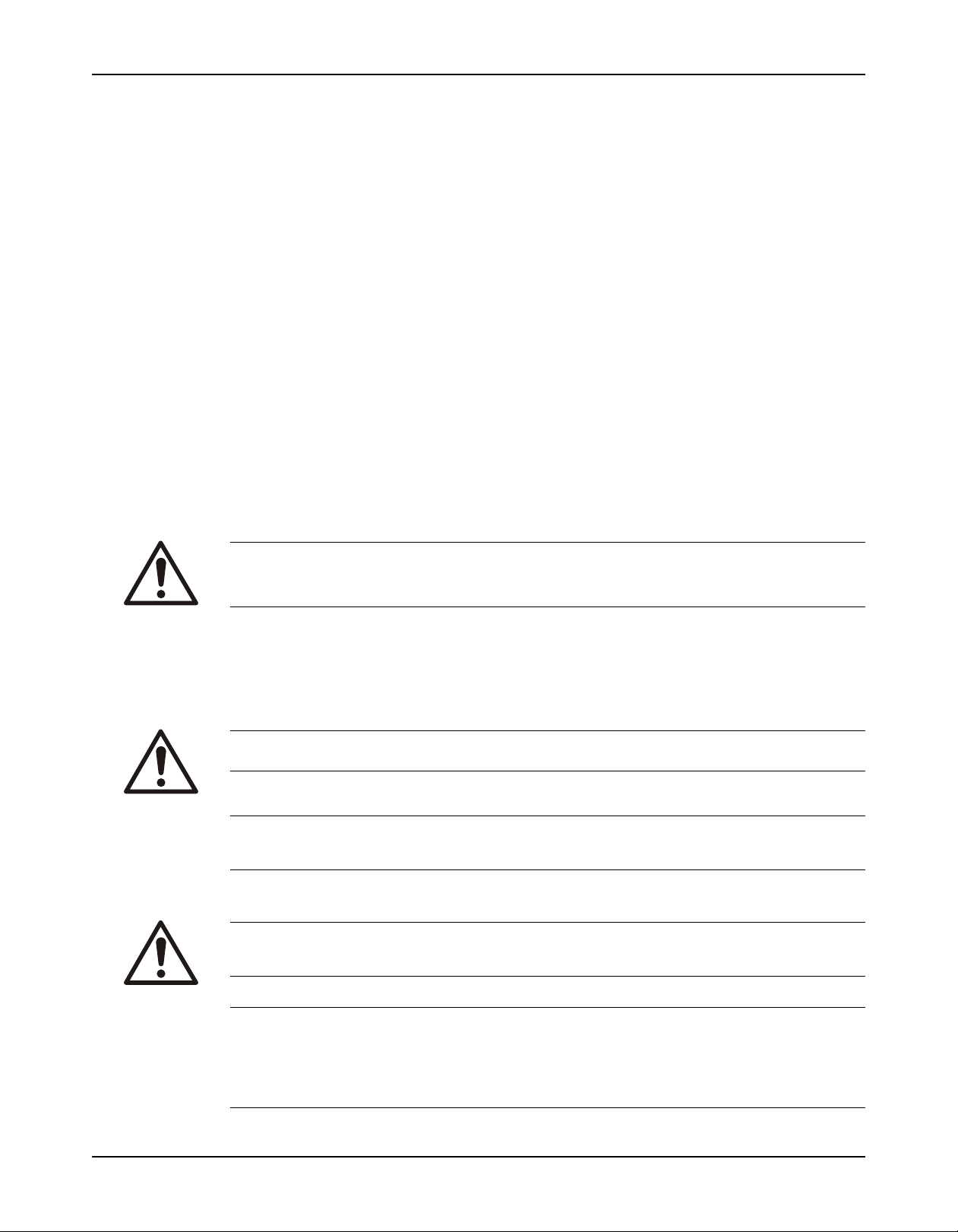
Hoist a bare pump using suitable slings under the bearing housing saddle on each end.
Figure 1: Example of the proper lifting method for a bare pump
Figure 2: Example of the proper lifting method for a bare pump
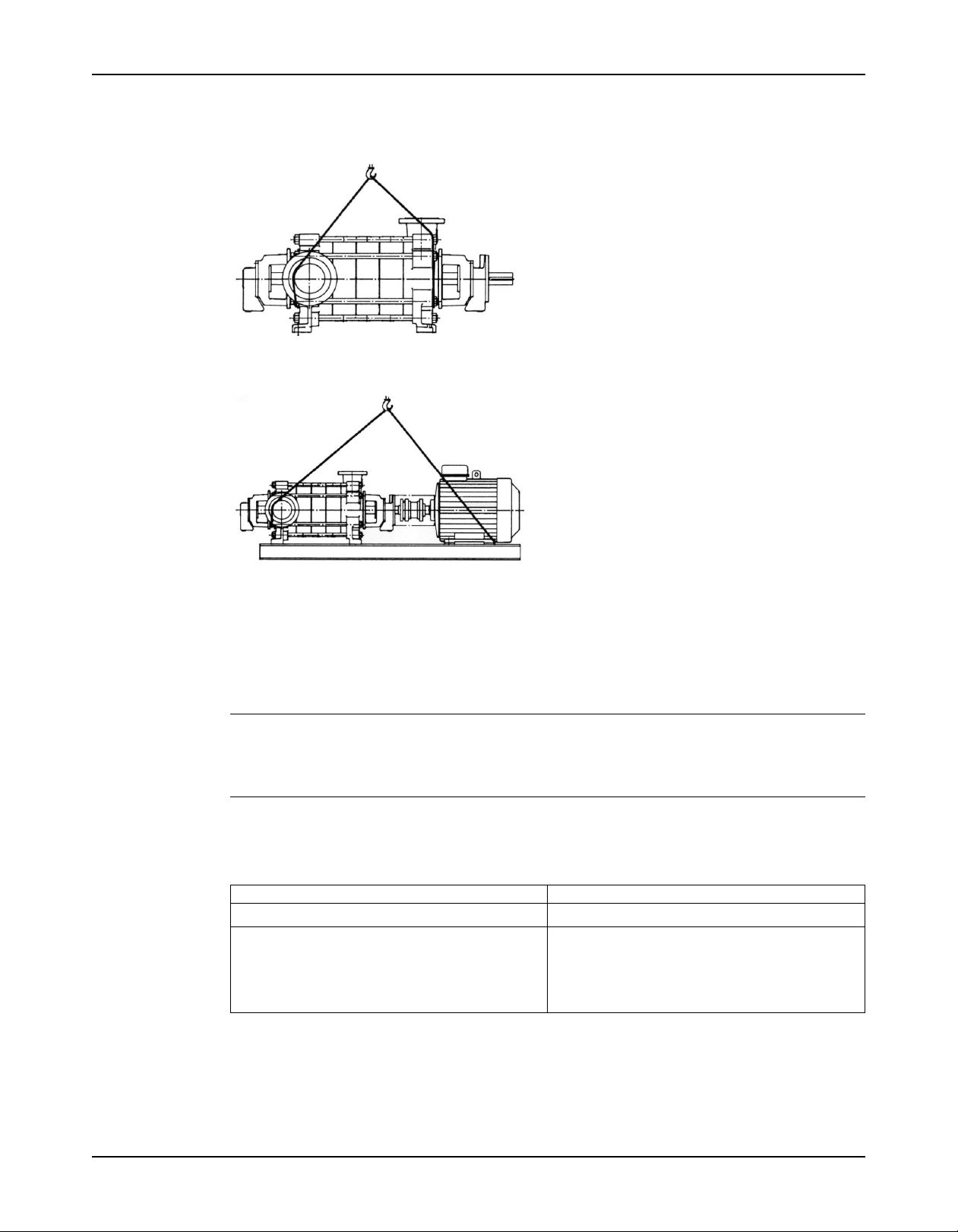
Baseplate-mounted units have lifting points for use with proper lifting devices.
Figure 3: Example of the proper lifting method for baseplate-mounted units with a driver
Storage guidelines
Storage location
The product must be stored in a covered and dry location free from heat, dirt, and vibrations.
NOTICE:
• Protect the product against humidity, heat sources, and mechanical damage.
• Do not place heavy weights on the packed product.
Pump storage requirements
Storage requirements depend on the amount of time that you store the unit. The normal
packaging is designed only to protect the unit during shipping.
Length of time in storage Storage requirements
Upon receipt/short-term (less than six months)
Long-term (more than six months)
• Store in a covered and dry location.
• Store in a covered and dry location.
• Store the unit free from heat, dirt, and vibrations.
• Rotate the shaft by hand several times at least
every three months.
You can purchase long-term storage treatment with the initial unit order or you can purchase it
and apply it after the units are already in the field. Contact your local ITT sales representative.
Model 3355 Installation, Operation, and Maintenance Manual 9
Page 12
Product Description
Product Description
General description
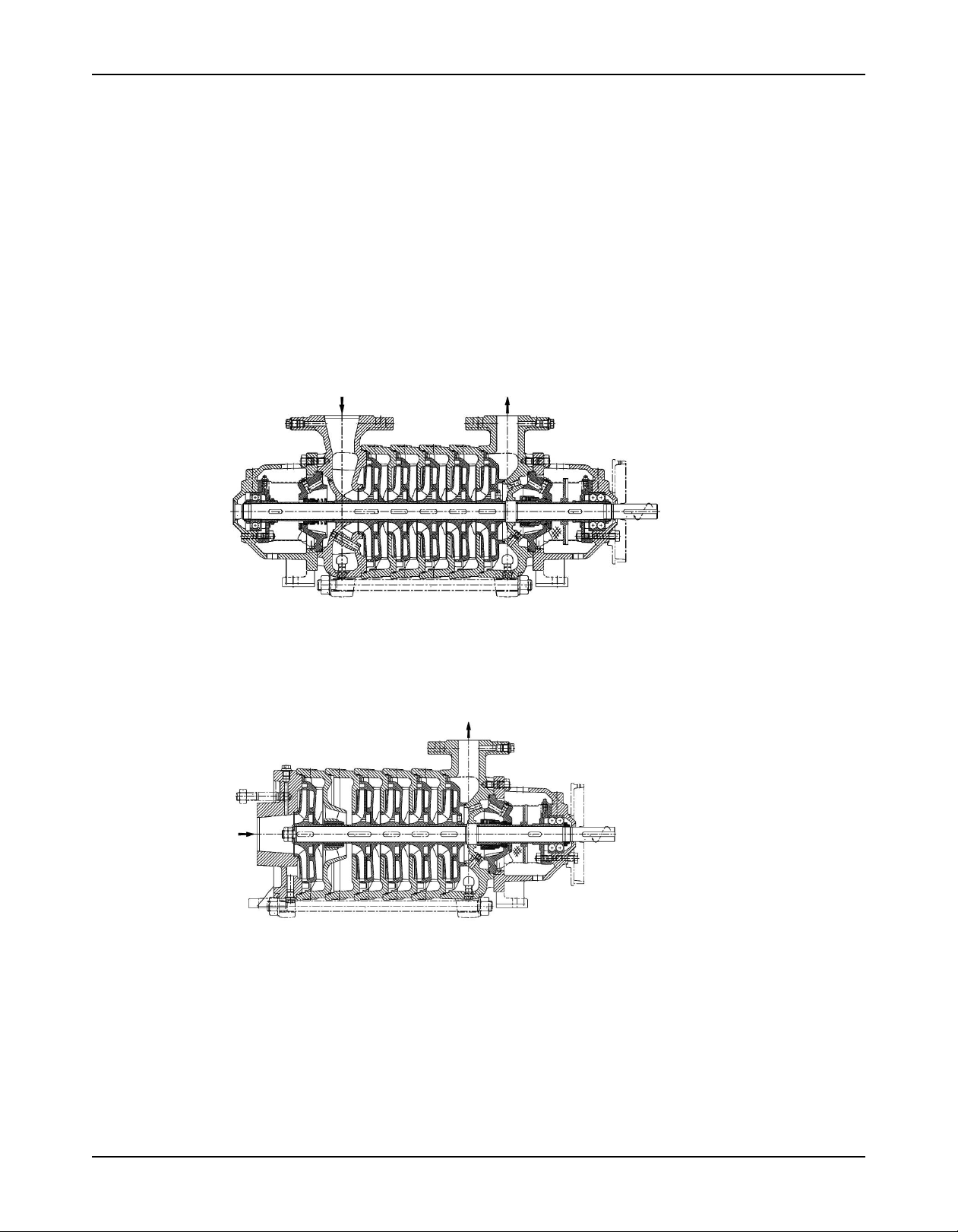
The Goulds Model 3355 is a radially-split, segmented casing, multistage pump that is designed
with modular interstage components. This pump is manufactured in cast iron and 316 stainless
steel. This pump can be configured in two ways:
• Radial suction (RS) configuration
• End suction (ES) configuration
Radial suction configuration
This configuration features radial suction and discharge nozzles. You can position each nozzle
either vertically or horizontally at 90° to either side. This design consists of two robust bearing
housings with traditional bearings and mechanical seals on each end of the pump.
End suction configuration
This configuration features an end suction nozzle in conjunction with a radial discharge nozzle.
You can position the radial discharge nozzle either vertically or horizontally at 90° to either side.
The suction end of the pump utilizes a product-lubricated bearing that elminates the need for a
second bearing housing and mechanical seal.
Direction of rotation
The standard pump rotation is clockwise. As an option, the radial suction (RS) configuration
can be shaft-driven from the suction end in a counterclockwise rotation.
Intended applications
These pumps are well-suited for reverse osmosis and boiler feed applications.
10 Model 3355 Installation, Operation, and Maintenance Manual
Page 13

Part description
Casing
The pump consists of three pressure boundary parts:
Diffusers
Multi−vane diffusers provide smooth pulsation−free operation and eliminate radial loads in
order to increase the life of the bearing. This pump uses a diffuser design that is not an integral
part of the interstage casing. Each diffuser is precision machined to perfectly match the
impeller hydraulics.
Impeller
The impeller is enclosed and keyed to the shaft. An inducer option is available for the end
suction arrangement.
Seal chamber
Product Description
• Suction casing - available in an end suction (ES) or radial suction (RS) configuration
The suction casing has 150 or 300 lb. flanges and the discharge casing has 300 or 600 lb.
flanges.
• Discharge casing
• Interstage casings - number is dependent on the number of stages
• The tapered bore seal chamber is self-venting and offers maximum cooling and flushing at
the seal face which increases the mechanical seal life.
• The standard seal arrangement features a single-balanced component seal on the
discharge end and a single-unbalanced component seal on the suction end of the RS
configuration.
• Internal flushing (Plan 01) is standard.
• External piping plans are not required.
Shaft
Shaft sleeves
Bearings
Baseplate
Couplings
The shaft is sized to transmit the required power across all operating conditions of the pump.
Impeller keyways are staggered in order to maintain a rotational shaft balance.
Renewable shaft sleeves protect the shaft in the seal chamber area which provides a longer
shaft life.
• Bearings are grease lubricated.
• The thrust bearing consists of:
• A double-row thrust bearing for pump sizes 1.5 x 2.5−7 and 2.5 x 4−8
• Two angular contact ball bearings for pump sizes 4 x 5−10 and 5 x 6−11
These thrust bearing configurations provide bi-directional load-carrying capability.
• The RS configuration uses a grease-lubricated radial ball bearing.
• The ES configuration uses a product−lubricated radial bearing located between the first
and second stages.
The pump and motor are mounted on a common baseplate. The rigid, fabricated steel design
reduces vibration and helps to maintain the positive alignment of the pump and motor.
The standard baseplate design facilitates non−spacer couplings.
Model 3355 Installation, Operation, and Maintenance Manual 11
Page 14
Product Description
Coupling guard
Steel coupling guards are available and are designed to comply with OSHA requirements.
Nameplate information
Important information for ordering
Every pump has a nameplate that provides information about the pump. The nameplate is
located on the pump casing.
When you order spare parts, identify this pump information:
• Model
• Size
• Serial number
• Item numbers of the required parts
Refer to the nameplate on the pump casing for most of the information. See Parts List for item
numbers.
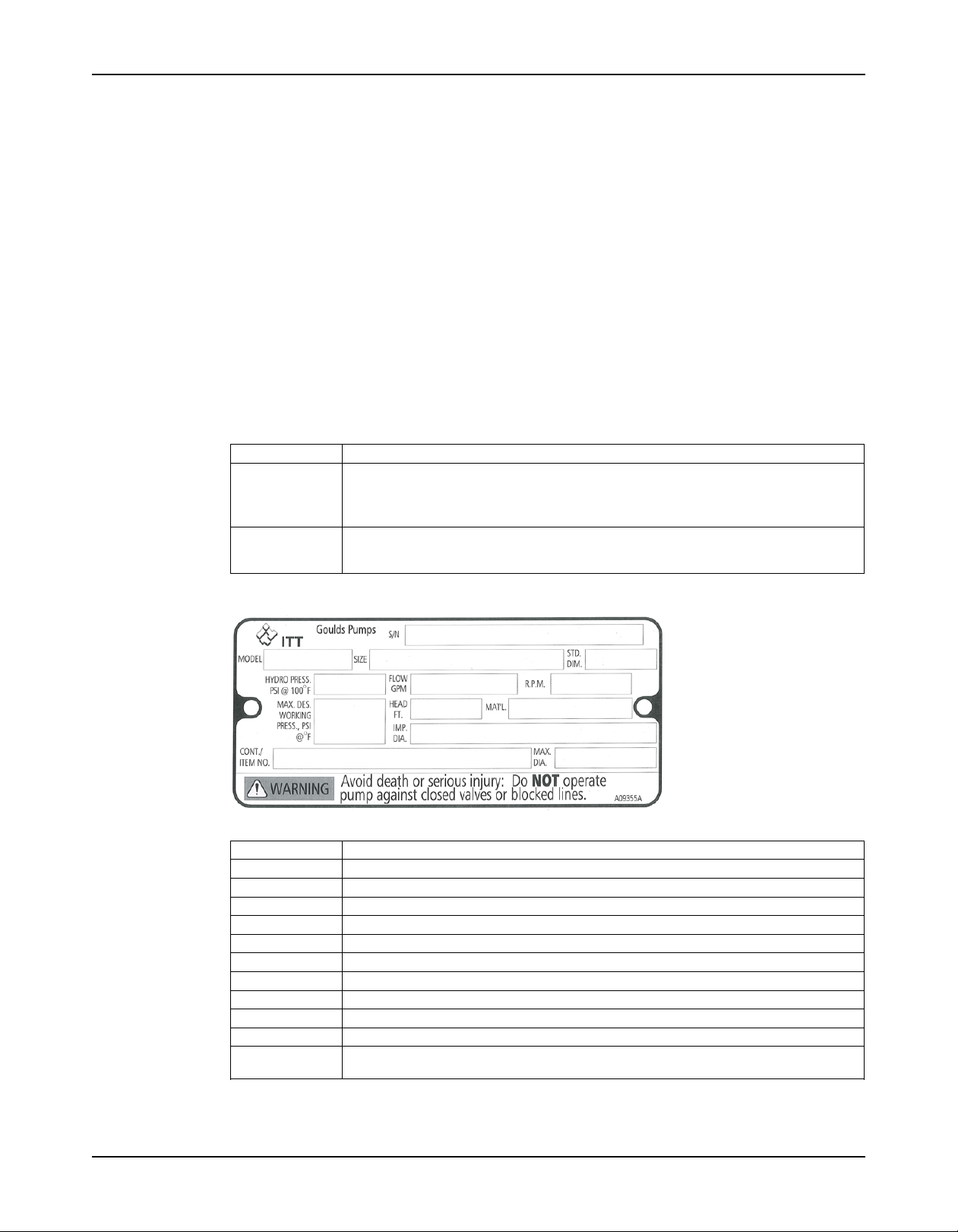
Nameplate types
Nameplate Description
Pump casing Provides information about the hydraulic characteristics of the pump.
ATEX If applicable, your pump unit might have an ATEX nameplate affixed to the pump, the
The formula for the pump size is: Discharge x Suction - Nominal Maximum Impeller
Diameter in inches.
(Example: 2x3-8)
baseplate, or the discharge head. The nameplate provides information about the
ATEX specifications of this pump.
Nameplate on the pump casing using English units
Table 1: Explanation of nameplate on the pump casing
Nameplate field Explanation
IMPLR. DIA. Impeller diameter, in inches
MAX. DIA. Maximum impeller diameter, in inches
GPM Rated pump flow, in gallons per minute
FT HD Rated pump head, in feet
RPM Rated pump speed, revolutions per minute
MOD. Pump model
SIZE Size of the pump
STD. NO. ANSI standard designation
MAT L. CONST. Material of which the pump is constructed
SER. NO. Serial number of the pump
MAX DSGN PSI Maximum pressure at 100ºF according to the pump design
@ 100ºF
12 Model 3355 Installation, Operation, and Maintenance Manual
Page 15
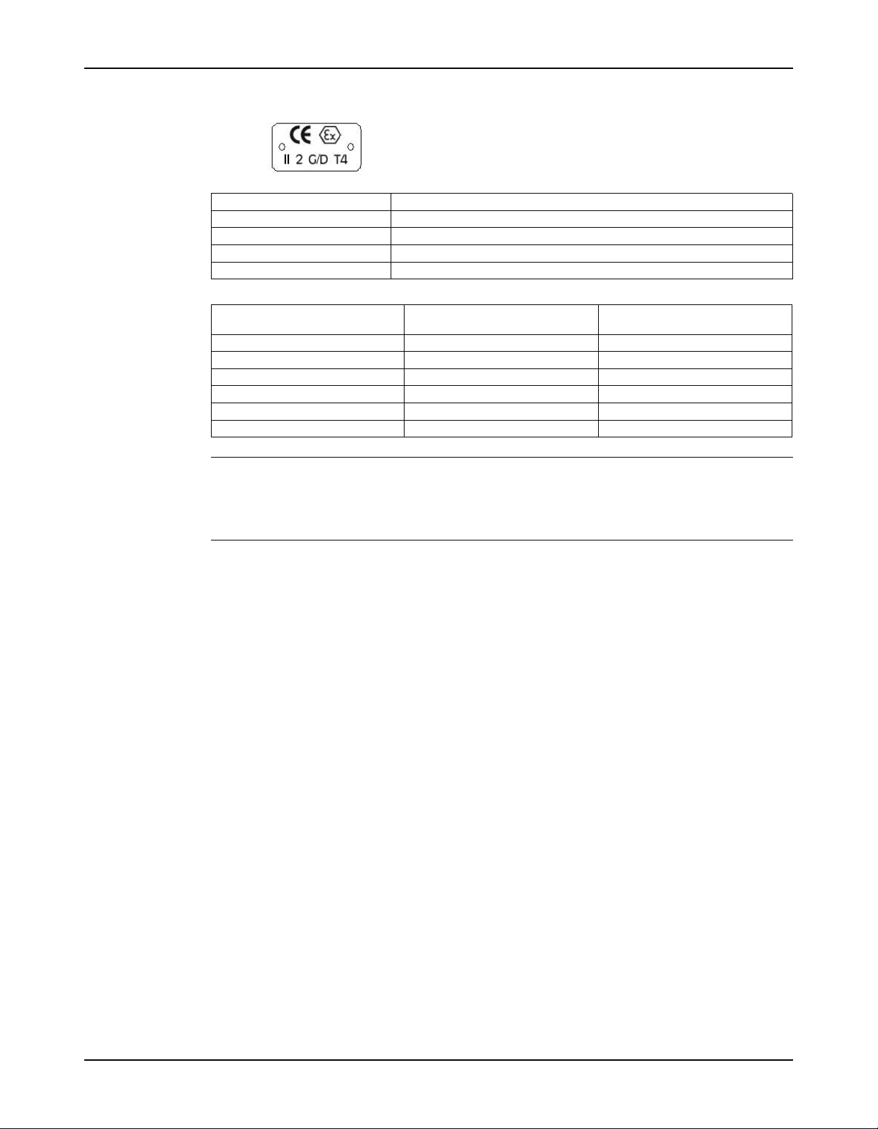
ATEX nameplate
Product Description
Nameplate field Explanation
II Group 2
2 Category 2
G/D Pump can be used when gas and dust are present
T4 Temperature class
Table 2: Temperature class definitions
Code Maximum permissible surface Minimum permissible surface
temperature in °F (°C) temperature in °F (°C)
T1 842 (450) 700 (372)
T2 572 (300) 530 (277)
T3 392 (200) 350 (177)
T4 275 (135) 235 (113)
T5 212 (100) Option not available
T6 185 (85) Option not available
NOTICE:
Make sure that the code classifications on the pump are compatible with the specific
environment in which you plan to install the equipment. If they are not compatible, do not
operate the equipment and contact your ITT representative before you proceed.
Model 3355 Installation, Operation, and Maintenance Manual 13
Page 16
Installation
Installation
Preinstallation
Precautions
WARNING:
• When installing in a potentially explosive environment, make sure that the motor is properly certified.
• You must earth (ground) all electrical equipment. This applies to the pump equipment, the driver, and
any monitoring equipment. Test the earth (ground) lead to verify that it is connected correctly.
• Electrical Connections must be made by certified electricians in compliance with all international,
national, state, and local rules.
NOTICE:
Supervision by an authorized ITT representative is recommended to ensure proper installation.
Failure to do so may result in equipment damage or decreased performance.
Pump location guidelines
WARNING:
Assembled units and their components are heavy. Failure to properly lift and support this equipment can
result in serious physical injury and/or equipment damage. Lift equipment only at the specifically identified
lifting points. Lifting devices such as eyebolts, slings, and spreaders must be rated, selected, and used for
the entire load being lifted.
Guideline Explanation/comment
Keep the pump as close to the liquid source as This minimizes the friction loss and keeps the
practically possible. suction piping as short as possible.
Make sure that the space around the pump is This facilitates ventilation, inspection, maintenance,
sufficient. and service.
A minimum of 3 feet (1 meter) is the recommendation.
If you require lifting equipment such as a hoist or This makes it easier to properly use the lifting
tackle, make sure that there is enough space above equipment and safely remove and relocate the
the pump. components to a safe location.
Protect the unit from weather and water damage This is applicable if nothing else is specified.
due to rain, flooding, and freezing temperatures.
Do not install and operate the equipment in closed Acceptable devices:
systems unless the system is constructed with
properly-sized safety devices and control devices.
Take into consideration the occurrence of unwanted The best pump location for noise and vibration
noise and vibration. absorption is on a concrete floor with subsoil
Foundation requirements
Requirements
• The foundation must be able to absorb any type of vibration and form a permanent, rigid
support for the unit.
• The location and size of the foundation bolt holes must match those shown on the
assembly drawing provided with the pump data package.
• Pressure relief valves
• Compression tanks
• Pressure controls
• Temperature controls
• Flow controls
If the system does not include these devices,
consult the engineer or architect in charge before
you operate the pump.
underneath.
14 Model 3355 Installation, Operation, and Maintenance Manual
Page 17
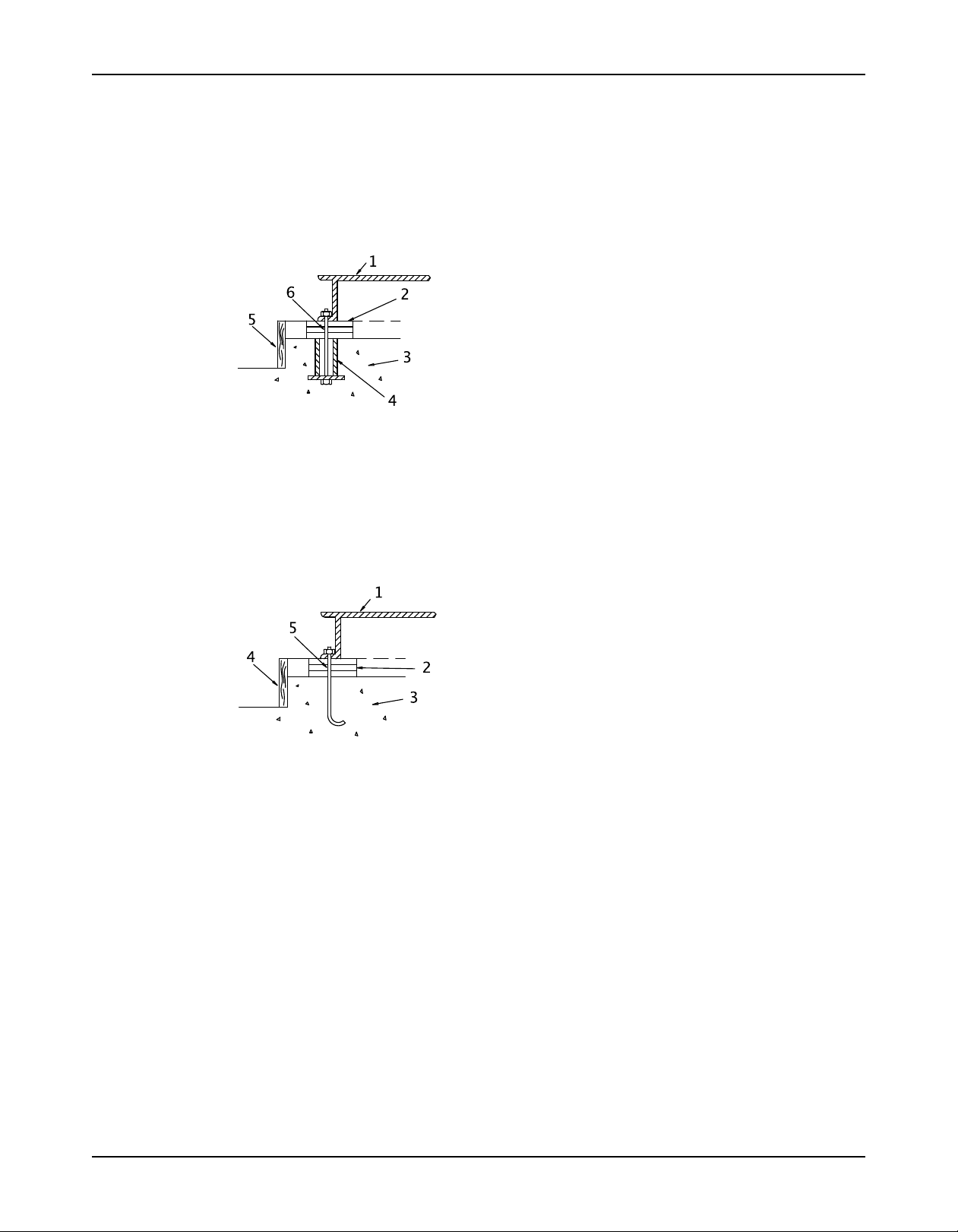
Sleeve-type bolts
Installation
• The foundation must weigh between two and three times the weight of the complete pump,
baseplate, and drive assembly.
• Provide a flat, substantial concrete foundation in order to prevent strain and distortion
when you tighten the foundation bolts.
• Sleeve-type and J-type foundation bolts are most commonly used. Both designs allow
movement for the final bolt adjustment.
1. Baseplate
2. Shims or wedges
3. Foundation
4. Sleeve
5. Dam
6. Bolt
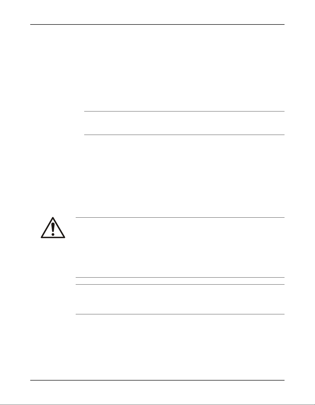
J-type bolts
1. Baseplate
2. Shims or wedges
3. Foundation
4. Dam
5. Bolt
Baseplate-mounting procedures
Prepare the baseplate for mounting
1. Remove all the attached equipment from the baseplate.
2. Clean the underside of the baseplate completely.
3. If applicable, coat the underside of the baseplate with an epoxy primer.
Use an epoxy primer only if you used an epoxy-based grout.
4. Remove the rust-proofing coat from the machined mounting pads using an appropriate
solvent.
5. Remove water and debris from the foundation-bolt holes.
Install the baseplate using shims or wedges
Required tools:
Model 3355 Installation, Operation, and Maintenance Manual 15
Page 18
Installation
• Two sets of shims or wedges for each foundation bolt
• Two machinist's levels
• Baseplate-leveling worksheet
1. If you use sleeve-type bolts, fill the bolt sleeves with packing material or rags to prevent
grout from entering the bolt holes.
2. Put the sets of wedges or shims on each side of each foundation bolt.
Make sure that the wedges extend 0.75 in. (19 mm) to 1.5 in. (38 mm) above the foundation
to provide adequate space for grouting. The wedges will provide adequate support for the
baseplate after it is grouted.
3. Lower the baseplate carefully onto the foundation bolts.
4. Put the machinist's levels across the mounting pads of the driver and the mounting pads of
the pump.
NOTICE:
Remove all dirt from the mounting pads in order to make sure that you achieve the correct
leveling. Failure to do so can result in equipment damage or decreased performance.
5. Level the baseplate both lengthwise and across by adding or removing shims or moving the
wedges.
These are the leveling tolerances:
• A maximum difference of 0.125 in. (3.2 mm) lengthwise
• A maximum difference of 0.059 in. (1.5 mm) across
You can use the baseplate-leveling worksheet when you take the readings.
6. Hand-tighten the nuts for the foundation.
Pump-to-driver alignment
Precautions
WARNING:
• Follow shaft alignment procedures in order to prevent catastrophic failure of drive components or
unintended contact of rotating parts. Follow the coupling installation and operation procedures from
the coupling manufacturer.
• Always disconnect and lock out power to the driver before you perform any installation or
maintenance tasks. Failure to disconnect and lock out driver power will result in serious physical
injury.
• Electrical connections must be made by certified electricians in compliance with all international,
national, state, and local rules.
• Refer to driver/coupling/gear manufacturers installation and operation manuals (IOM) for specific
instructions and recommendations.
NOTICE:
Proper alignment is the responsibility of the installer and the user of the unit. Check the
alignment of frame-mounted units before you operate the unit. Failure to do so can result in
equipment damage or decreased performance.
Alignment checks
When to perform alignment checks
You must perform alignment checks under these circumstances:
• The process temperature changes.
• The piping changes.
• The pump has been serviced.
16 Model 3355 Installation, Operation, and Maintenance Manual
Page 19

Types of alignment checks
Type of check When it is used
Initial alignment (cold alignment) Prior to operation when the pump and the driver are at ambient
check temperature.
Final alignment (hot alignment) After operation when the pump and the driver are at operating
check temperature.
Initial alignment (cold alignment) checks
When Why
Before you grout the baseplate This ensures that alignment can be accomplished.
After you grout the baseplate This ensures that no changes have occurred during the grouting
process.
After you connect the piping This ensures that pipe strains have not altered the alignment.
If changes have occurred, you must alter the piping to remove pipe
strains on the pump flanges.
Final alignment (hot alignment) checks
When Why
After the first run This ensures correct alignment when both the pump and the driver
are at operating temperature.
Periodically This follows the plant operating procedures.
Permitted indicator values for alignment checks
Installation
NOTICE:
The specified permitted reading values are valid only at operating temperature. For cold
settings, other values are permitted. You must use the correct tolerances. Failure to do so can
result in misalignment and reduced pump reliability.
When dial indicators are used to check the final alignment, the pump and drive unit are
correctly aligned when these conditions are true:
• The total indicator runout is a maximum of 0.002 in. (0.05 mm) at operating temperature.
• The tolerance of the indicator is 0.0005 in./in. (0.0127 mm/mm) of indicator separation at
operating temperature.
Alignment measurement guidelines
Guideline Explanation
Rotate the pump coupling half and the driver This prevents incorrect measurement.
coupling half together so that the indicator rods
have contact with the same points on the driver
coupling half.
Move or shim only the driver in order to make This prevents strain on the piping installations.
adjustments.
Make sure that the hold-down bolts for the driver This keeps the driver stationary since movement
feet are tight when you take indicator measure- causes incorrect measurement.
ments.
Make sure that the hold-down bolts for the driver This makes it possible to move the driver when you
feet are loose before you make alignment correc- make alignment corrections.
tions.
Check the alignment again after any mechanical This corrects any misalignments that an adjustment
adjustments. may have caused.
Attach the dial indicators for alignment
You must have two dial indicators in order to complete this procedure.
1. Attach two dial indicators on the pump coupling half (X):
a) Attach one indicator (P) so that the indicator rod comes into contact with the perimeter
of the driver coupling half (Y).
This indicator is used to measure parallel misalignment.
Model 3355 Installation, Operation, and Maintenance Manual 17
Page 20

Installation
b) Attach the other indicator (A) so that the indicator rod comes into contact with the inner
end of the driver coupling half.
This indicator is used to measure angular misalignment.
2. Rotate the pump coupling half (X) in order to check that the indicators are in contact with
the driver coupling half (Y) but do not bottom out.
3. Adjust the indicators if necessary.
Pump-to-driver alignment instructions
Perform angular alignment for a vertical correction
1. Set the angular alignment indicator to zero at the top-center position (12 o’clock) of the
driver coupling half (Y).
2. Rotate the indicator to the bottom-center position (6 o’clock).
3. Record the indicator reading.
When the reading value is... Then...
Negative The coupling halves are farther apart at the
Positive The coupling halves are closer at the bottom than
bottom than at the top. Perform one of these
steps:
• Add shims in order to raise the feet of the
driver at the shaft end.
• Remove shims in order to lower the feet of the
driver at the other end.
at the top. Perform one of these steps:
• Remove shims in order to lower the feet of the
driver at the shaft end.
• Add shims in order to raise the feet of the
driver at the other end.
Perform angular alignment for a horizontal correction
1. Set the angular alignment indicator (A) to zero on left side of the driver coupling half (Y),
90° from the top-center position (9 o’clock).
2. Rotate the indicator through the top-center position to the right side, 180° from the start
position (3 o’clock).
3. Record the indicator reading.
When the reading value is... Then...
Negative The coupling halves are farther apart on the right side than
Positive The coupling halves are closer together on the right side
the left. Perform one of these steps:
• Slide the shaft end of the driver to the left.
• Slide the opposite end to the right.
than the left. Perform one of these steps:
• Slide the shaft end of the driver to the right.
• Slide the opposite end to the left.
Perform parallel alignment for a vertical correction
Refer to the alignment table in "Permitted indicator values for alignment checks" (see Table of
Contents for location of table) for the proper cold alignment value based on the motor
temperature rise and the pump operating temperature.
Before you start this procedure, make sure that the dial indicators are correctly set up.
A unit is in parallel alignment when the parallel indicator (P) does not vary by more than as
measured at four points 90° apart at the operating temperature.
1. Set the parallel alignment indicator (P) to zero at the top-center position (12 o’clock) of the
driver coupling half (Y).
2. Rotate the indicator to the bottom-center position (6 o’clock).
3. Record the indicator reading.
18 Model 3355 Installation, Operation, and Maintenance Manual
Page 21

When the reading value is... Then...
Negative The pump coupling half (X) is lower than the
Positive The pump coupling half (X) is higher than the
NOTICE:
4. Repeat the previous steps until the permitted reading value is achieved.
Perform parallel alignment for a horizontal correction
A unit is in parallel alignment when the parallel indicator (P) does not vary by more than as
measured at four points 90° apart at the operating temperature.
1. Set the parallel alignment indicator (P) to zero on the left side of the driver coupling half (Y),
90° from the top-center position (9 o’clock).
2. Rotate the indicator through the top-center position to the right side, 180° from the start
position (3 o’clock).
3. Record the indicator reading.
When the reading value is... Then...
Negative The driver coupling half (Y) is to the left of the
Positive The driver coupling half (Y) is to the right of the
Installation
driver coupling half (Y). Remove shims of a
thickness equal to half of the indicator reading
value under each driver foot.
driver coupling half (Y). Add shims of a thickness
equal to half of the indicator reading value to each
driver foot.
pump coupling half (X).
pump coupling half (X).
4. Slide the driver carefully in the appropriate direction.
NOTICE:Make sure to slide the driver evenly. Failure to do so can negatively affect
horizontal angular correction.
5. Repeat the previous steps until the permitted reading value is achieved.
Perform complete alignment for a vertical correction
1. Set the angular and parallel dial indicators to zero at the top-center position (12 o’clock) of
the driver coupling half (Y).
2. Rotate the indicators to the bottom-center position (6 o’clock).
3. Record the indicator readings.
4. Make corrections according to the separate instructions for angular and parallel alignment
until you obtain the permitted reading values.
Perform complete alignment for a horizontal correction
1. Set the angular and parallel dial indicators to zero at the left side of the driver coupling half
(Y), 90° from the top-center position (9 o’clock).
2. Rotate the indicators through the top-center position to the right side, 180° from the start
position (3 o’clock).
3. Record the indicator readings.
4. Make corrections according to the separate instructions for angular and parallel alignment
until you obtain the permitted reading values.
Grout the baseplate
Required equipment:
• Cleaners: Do not use an oil-based cleaner because the grout will not bond to it. See the
instructions provided by the grout manufacturer.
Model 3355 Installation, Operation, and Maintenance Manual 19
Page 22

Installation
1. Clean all the areas of the baseplate that will come into contact with the grout.
2. Build a dam around the foundation.
3. Thoroughly wet the foundation that will come into contact with the grout.
4. Pour grout through the grout hole into the baseplate up to the level of the dam.
When you pour the grout, remove air bubbles from it by using one of these methods:
• Puddle with a vibrator.
• Pump the grout into place.
5. Allow the grout to set.
1. Baseplate
2. Shims or wedges
3. Grout
4. Foundation
5. Sleeve
6. Dam
7. Bolt
6. Fill the remainder of the baseplate with grout, and allow the grout to set for at least 48
hours.
1. Baseplate
2. Grout
3. Foundation
4. Dam
5. Bolt
7. Tighten the foundation bolts.
8. Recheck the alignment.
Piping checklists
Fastening
WARNING:
• Only use fasteners of the proper size and material.
• Replace all corroded fasteners.
• Make sure that all fasteners are properly tightened and that there are no missing fasteners.
20 Model 3355 Installation, Operation, and Maintenance Manual
Page 23

General piping checklist
Precautions
CAUTION:
• Never draw piping into place by using force at the flanged connections of the pump. This can
impose dangerous strains on the unit and cause misalignment between the pump and driver. Pipe
strain adversely affects the operation of the pump, which results in physical injury and damage to
the equipment.
• Vary the capacity with the regulating valve in the discharge line. Never throttle the flow from the
suction side. This action can result in decreased performance, unexpected heat generation, and
equipment damage.
CAUTION:
Flange loads from the piping system, including those from the thermal expansion of the piping, must not
exceed the limits of the pump. Casing deformation can result in contact with rotating parts, which can
result in excess heat generation, sparks, and premature failure.
Piping guidelines
Guidelines for piping are given in the Hydraulic Institute Standards available from the Hydraulic
Institute at 9 Sylvan Way, Parsippany, NJ 07054-3802. You must review this document before
you install the pump.
Installation
Checklist
Check Explanation/comment Checked
Check that all piping is supported This helps to prevent:
independently of, and lined up
naturally with, the pump flange.
Keep the piping as short as pos- This helps to minimize friction losses.
sible.
Check that only necessary fittings This helps to minimize friction losses.
are used.
Do not connect the piping to the —
pump until:
• The grout for the baseplate or
sub-base becomes hard.
• The hold-down bolts for the
pump and the driver are tightened.
Make sure that all the piping joints This prevents air from entering the piping system or
and fittings are airtight. leaks that occur during operation.
If the pump handles corrosive
fluids, make sure that the piping
allows you to flush out the liquid
before you remove the pump.
If the pump handles liquids at
elevated temperatures, make
sure that the expansion loops and
joints are properly installed.
Make sure that all piping compo- —
nents, valves and fittings, and
pump branches are clean prior to
assembly.
• Strain on the pump
• Misalignment between the pump and the drive unit
• Wear on the pump bearings, seal, and shafting
Model 3355 Installation, Operation, and Maintenance Manual 21
Page 24

Installation
Example: Piping installation with a vent line
Suction-piping checklist
Performance curve reference
Net positive suction head available (NPSHA) must always exceed NPSH required (NPSHR) as
shown on the published performance curve of the pump.
Suction-piping checks
Check Explanation/comment Checked
Check that the distance between This minimizes the risk of cavitathe inlet flange of the pump and tion in the suction inlet of the
the closest elbow is at least two pump due to turbulence.
pipe diameters.
Check that elbows in general do
not have sharp bends.
Check that the suction piping is The suction piping must never
one or two sizes larger than the have a smaller diameter than the
suction inlet of the pump. suction inlet of the pump.
Install an eccentric reducer between the pump inlet and the
suction piping.
Check that the eccentric reducer
at the suction flange of the pump
has the following properties:
• Sloping side down
• Horizontal side at the top
When suction strainers or suction Suction strainers help to prevent
bells are used, check that they are clogging.
at least three times the area of the
suction piping.
If more than one pump operates This recommendation helps you
from the same liquid source, to achieve a higher pump perforcheck that separate suction-piping mance.
lines are used for each pump.
If necessary, make sure that the —
suction piping includes a drain
valve and that it is correctly installed.
Mesh holes with a minimum diameter of 1/16 in. (1.6 mm) are
recommended.
22 Model 3355 Installation, Operation, and Maintenance Manual
Page 25

Liquid source below the pump
Check Explanation/comment Checked
Make sure that the suction piping This helps to prevent the occuris free from air pockets. rence of air and cavitation in the
Check that the suction piping —
slopes upwards from the liquid
source to the pump inlet.
If the pump is not self-priming, Use a foot valve with a diameter
check that a device for priming the that is at least equivalent to the
pump is installed. diameter of the suction piping.
Liquid source above the pump
Check Explanation/comment Checked
Check that an isolation valve is This permits you to close the line
installed in the suction piping at a during pump inspection and maindistance of at least two times the tenance.
pipe diameter from the suction
inlet.
Make sure that the suction piping This helps to prevent the occuris free from air pockets. rence of air and cavitation in the
Check that the piping is level or —
slopes downward from the liquid
source.
Make sure that no part of the —
suction piping extends below the
suction flange of the pump.
Make sure that the suction piping This prevents air from entering the
is adequately submerged below pump through a suction vortex.
the surface of the liquid source.
Installation
pump inlet.
Do not use the isolation valve to
throttle the pump. Throttling can
cause these problems:
• Loss of priming
• Excessive temperatures
• Damage to the pump
• Voiding the warranty
pump inlet.
Discharge piping checklist
Checklist
Check Explanation/comment Checked
Check that an isolation valve is in- The isolation valve is required for:
stalled in the discharge line.
Check that a check valve is installed in The location between the isolation valve and the
the discharge line, between the isola- pump allows inspection of the check valve.
tion valve and the pump discharge
outlet.
If increasers are used, check that they
are installed between the pump and
the check valve.
If quick-closing valves are installed in This protects the pump from surges and water
the system, check that cushioning de- hammer.
vices are used.
Final piping checklist
Check Explanation/comment Checked
Check that the shaft rotates Rotate the shaft by hand. Make
smoothly. sure there is no rubbing that can
• Priming
• Regulation of flow
• Inspection and maintenance of the pump
The check valve prevents damage to the pump and
seal due to the back flow through the pump, when
the drive unit is shut off. It is also used to restrain
the liquid flow.
lead to excess heat generation or
sparks.
Model 3355 Installation, Operation, and Maintenance Manual 23
Page 26

Installation
Check Explanation/comment Checked
Re-check the alignment to make If pipe strain exists, then correct
sure that pipe strain has not the piping.
caused any misalignment.
24 Model 3355 Installation, Operation, and Maintenance Manual
Page 27

Commissioning, Startup, Operation, and Shutdown
Commissioning, Startup, Operation, and
Shutdown
Preparation for startup
DANGER:
Avoid death or serious injury. Explosion and/or seizure of pump can cause fire and/or burns. Never
operate pump past the pressure and temperature limits shown on the nameplate on the pump.
WARNING:
• Any pressure-containing device can explode, rupture, or discharge its contents if it is overpressurized. Take all necessary measures to avoid over-pressurization.
• Failure to follow these precautions before you start the unit will lead to serious personal injury and
equipment failure.
• Do not operate the pump below the minimum rated flows or with the suction or discharge valves
closed. These conditions can create an explosive hazard due to vaporization of pumped fluid and
can quickly lead to pump failure and physical injury.
• Avoid death or serious injury. Leaking fluid can cause fire and/or burns. Operating the pump above
maximum rated flow shown on the pump curve leading to an increase in horsepower and vibration
along with an increase in NPSHr resulting in mechanical seal and/or shaft failure and/or loss of
prime.
• Avoid death or serious injury. Leaking fluid can cause fire and/or burns. Speed of pump must reach
2000 rpm for 2 pole motors and 1000 rpm for 4 pole motors within 10 seconds or an increase in
vibration and rotor deflection and decrease in rotor stability leading to mechanical seal and/or shaft
failure and/or pump seizure can occur.
• Never operate the pump without the coupling guard correctly installed.
• The coupling used in an ATEX classified environment must be properly certified.
• Always disconnect and lock out power to the driver before you perform any installation or
maintenance tasks. Failure to disconnect and lock out driver power will result in serious physical
injury.
• Electrical connections must be made by certified electricians in compliance with all international,
national, state, and local rules.
• Refer to driver/coupling/gear manufacturers installation and operation manuals (IOM) for specific
instructions and recommendations.
• Operating the pump in reverse rotation can result in the contact of metal parts, heat generation, and
breach of containment.
• Make sure to properly lubricate the bearings. Failure to do so can result in excess heat generation,
sparks, and premature failure.
• Avoid death or serious injury. Explosion and/or seizure of pump can cause fire and/or burns. Assure
balance line is installed and either piped to the pump suction or back to the suction vessel to avoid
vaporization of pumped fluid.
DANGER:
Avoid death or serious injury. Leaking fluid can cause fire and/or burns. Assure all openings are sealed
off prior to filling pump.
Precautions
NOTICE:
• Verify the driver settings before you start any pump.
You must follow these precautions before you start the pump:
• Flush and clean the system thoroughly to remove dirt or debris in the pipe system in order
to prevent premature failure at initial startup.
Model 3355 Installation, Operation, and Maintenance Manual 25
Page 28

Commissioning, Startup, Operation, and Shutdown
• Bring variable-speed drivers to the rated speed as quickly as possible.
• If temperatures of the pumped fluid will exceed 200°F (93°C), then warm up the pump prior
to operation. Circulate a small amount of fluid through the pump until the casing
temperature is within 100°F (38°C) of the fluid temperature. Accomplish this by flowing
fluid from pump inlet to discharge drain (optionally, the casing vent can be included in
warm-up circuit but not required). Soak for (2) hours at process fluid temperature.
At initial startup, do not adjust the variable-speed drivers or check for speed governor or overspeed trip settings while the variable-speed driver is coupled to the pump. If the settings have
not been verified, then uncouple the unit and refer to instructions supplied by the driver
manufacturer.
Remove the coupling guard
1. Remove the nut, bolt, and washers from the slotted hole in the center of the coupling guard.
2. Slide the driver half of the coupling guard toward the pump.
3. Remove the nut, bolt, and washers from the driver half of the coupling guard.
4. Remove the driver-side end plate.
5. Remove the driver half of the coupling guard:
a) Slightly spread the bottom apart.
b) Lift upwards.
6. Remove the remaining nut, bolt, and washers from the pump half of the coupling guard.
It is not necessary to remove the end plate from the pump side of the bearing housing. You
can access the bearing-housing tap bolts without removing this end plate if maintenance of
internal pump parts is necessary.
7. Remove the pump half of the coupling guard:
a) Slightly spread the bottom apart.
b) Lift upwards.
Check the rotation - Frame Mounted
WARNING:
• Operating the pump in reverse rotation can result in the contact of metal parts, heat generation, and
breach of containment.
• Always disconnect and lock out power to the driver before you perform any installation or
maintenance tasks. Failure to disconnect and lock out driver power will result in serious physical
injury.
• Electrical connections must be made by certified electricians in compliance with all international,
national, state, and local rules.
• Refer to driver/coupling/gear manufacturers installation and operation manuals (IOM) for specific
instructions and recommendations.
1. Lock out power to the driver.
2. Make sure that the coupling hubs are fastened securely to the shafts.
3. Unlock power to the driver.
4. Make sure that everyone is clear, and then jog the driver long enough to determine that the
direction of rotation corresponds to the arrow on the bearing housing or close-coupled
frame.
5. Lock out power to the driver.
26 Model 3355 Installation, Operation, and Maintenance Manual
Page 29

Couple the pump and driver
WARNING:
• Always disconnect and lock out power to the driver before you perform any installation or
maintenance tasks. Failure to disconnect and lock out driver power will result in serious physical
injury.
• Electrical connections must be made by certified electricians in compliance with all international,
national, state, and local rules.
• Refer to driver/coupling/gear manufacturers installation and operation manuals (IOM) for specific
instructions and recommendations.
•
1. Check the gap between the coupling hubs against the dimensions shown on the elevation
drawing or as stamped on the coupling hub. For any necessary adjustment, move the
driver not the pump.
Motors with sleeve bearings may be manufactured with 1/4 or 1/2 in. (6.35 or 12.7 mm) end
movement (float) in the motor rotor. For limited end-float arrangement, the gap between the
coupling halves must be set in a different manner. If specific directions are not indicated in
the motor instructions, then follow this procedure:
NOTICE:
If the driver was mounted at the factory, the setting for the coupling is already determined.
a) Slide the rotor towards the outboard end of the motor as far as it will go and mark the
shaft at the motor frame.
b) Slide the rotor towards the inboard end of the motor as far as it will go and mark the
shaft again.
The distance between the marks should be either 1/2 or 1/4 in. (6.35 or 12.7 mm) if the
motor is arranged for limited end-float travel.
c) Scribe a third mark on the shaft halfway between the scribe marks made in the previous
steps.
d) Clamp the rotor in place.
Commissioning, Startup, Operation, and Shutdown
1. Sleeve bearing
2. Thrust collar
3. Coupling
2. Use the instructions from the coupling manufacturer to lubricate and install the coupling.
3. Check the angular and parallel alignment of the coupling halves. See Pump-to-driver
alignment in the Installation chapter.
Install the coupling guard
1. De-energize the motor, place the motor in a locked-out position, and place a caution tag at
the starter that indicates the disconnect.
Model 3355 Installation, Operation, and Maintenance Manual 27
Page 30

Commissioning, Startup, Operation, and Shutdown
2. Put the pump-half of the coupling guard in place:
a) Slightly spread the bottom apart.
b) Place the coupling guard half over the pump-side end plate.
1. Annular groove
2. Pump-side end plate
3. Driver
4. Pump half of the coupling guard
The annular groove in the coupling guard half must fit around the end plate.
1. Annular groove
2. End plate (pump end)
3. Guard half
3. Use a bolt, a nut, and two washers to secure the coupling guard half to the end plate.
Tighten securely.
28 Model 3355 Installation, Operation, and Maintenance Manual
Page 31

Commissioning, Startup, Operation, and Shutdown
1. Nut
2. Washer
3. Bolt
4. Put the driver half of the coupling guard in place:
a) Slightly spread the bottom apart.
b) Place the driver half of the coupling guard over the pump half of the coupling guard.
The annular groove in the coupling guard half must face the motor.
5. Place the driver-side end plate over the motor shaft.
6. Place the driver-side end plate in the annular groove of the driver-half of the coupling
guard.
7. Use a bolt, a nut, and two washers to secure the coupling guard half to the end plate. Handtighten only.
The hole is located on the driver-side of the coupling guard half.
8. Slide the driver-half of the coupling guard towards the motor so that the coupling guard
completely covers the shafts and coupling.
9. Use a nut, a bolt, and two washers to secure the coupling guard halves together.
10. Tighten all nuts on the guard assembly.
WARNING:
Never operate the pump without the coupling guard correctly installed.
Pump priming
CAUTION:
Do not run the pump dry.
Never start the pump until it has been properly primed. Several different methods of priming
can be used, depending on the type of installation and service involved.
Prime the pump with the suction supply above the pump
1. Slowly open the suction isolation valve.
2. Open the air vents on the suction and discharge piping, the casing, the seal chamber, and
the seal piping, if provided, until all air is vented and only the pumped fluid flows out.
3. Close the air vents.
Prime the pump with the suction supply below the pump
Use a foot valve and an outside source of liquid in order to prime the pump. The liquid can
come from one of these sources:
• A priming pump
• A pressurized discharge line
• Another outside supply
1. Close the discharge isolation valve.
2. Open the air vent valves in the casing.
Model 3355 Installation, Operation, and Maintenance Manual 29
Page 32

Commissioning, Startup, Operation, and Shutdown
3. Open the air vents in the seal covers.
4. Open the valve in the outside supply line until only liquid escapes from the vent valves.
5. Close the vent valves.
6. Close the outside supply line.
Other methods of priming the pump
You can also use these methods in order to prime the pump:
• Prime by ejector
• Prime by automatic priming pump
Start the pump
WARNING:Immediately observe the pressure gauges. If discharge pressure is not quickly attained, stop
the driver immediately, reprime, and attempt to restart the pump.
CAUTION:
• Immediately observe the pressure gauges. If discharge pressure is not quickly attained, stop the
driver, reprime, and attempt to restart the pump.
• Observe the pump for vibration levels, bearing temperature, and excessive noise. If normal levels
are exceeded, shut down the pump and resolve the issue.
• On pure or purge-oil mist-lubricated units, remove the viewing port plugs to verify that oil mist
flowing properly. Replace the plugs.
• On frame mounted units, ensure that the oil level is correct prior to starting pump. Close coupled
pumps do not have oil lubricated bearings.
• Ensure all flush and cooling systems are operating correctly prior to starting pump.
Before you start the pump, you must perform these tasks:
• Open the suction valve.
• Open any recirculation or cooling lines.
1. Fully close or partially open the discharge valve, depending on system conditions.
2. Start the driver.
3. Slowly open the discharge valve until the pump reaches the desired flow.
4. Immediately check the pressure gauge to ensure that the pump quickly reaches the correct
discharge pressure.
5. If the pump fails to reach the correct pressure, perform these steps:
a) Stop the driver.
b) Prime the pump again.
c) Restart the driver.
6. Monitor the pump while it is operating:
a) Check the pump for bearing temperature, excessive vibration, and noise.
b) If the pump exceeds normal levels, then shut down the pump immediately and correct
the problem.
7. Repeat steps 5 and 6 until the pump runs properly.
30 Model 3355 Installation, Operation, and Maintenance Manual
Page 33

Pump operation precautions
General considerations
CAUTION:
• Vary the capacity with the regulating valve in the discharge line. Never throttle the flow from the
suction side since this can result in decreased performance, unexpected heat generation, and
equipment damage.
Do not overload the driver. Driver overload can result in unexpected heat generation and equipment
damage. The driver can overload in these circumstances:
• The specific gravity of the pumped fluid is greater than expected.
• The pumped fluid exceeds the rated flow rate.
• Do not operate pump past the maximum flow. For maximum flow refer to the pump performance
curve.
• Do not overload the driver. Driver overload can result in unexpected heat generation and equipment
damage. The driver can overload in these circumstances:
• The specific gravity of the pumped fluid is greater than expected.
• The pumped fluid exceeds the rated flow rate.
• Do not operate pump below hydraulic or thermal minimum flow. For hydraulic minimum flows refer
to technical manual and pump performance curve. To calculate thermal minimum flow, refer to HI
Centrifugal Pumps for Design and Application ANSI/HI 1.3-2000.
• Make sure to operate the pump at or near the rated conditions. Failure to do so can result in pump
damage from cavitation or recirculation.
Commissioning, Startup, Operation, and Shutdown
Operation at reduced capacity
WARNING:
Never operate any pumping system with a blocked suction and discharge. Operation, even for a brief
period under these conditions, can cause confined pumped fluid to overheat, which results in a violent
explosion. You must take all necessary measures to avoid this condition. If pump becomes plugged shut
down and unplug prior to restarting pump.
CAUTION:
• The pump and system must be free of foreign objects. If pump becomes plugged, shut down and
unplug prior to restarting pump.
• Avoid excessive vibration levels. Excessive vibration levels can damage the bearings, stuffing box
or seal chamber, and the mechanical seal, which can result in decreased performance.
• Avoid increased radial load. Failure to do so can cause stress on the shaft and bearings.
• Avoid heat build-up. Failure to do so can cause rotating parts to score or seize.
• Avoid cavitation. Failure to do so can cause damage to the internal surfaces of the pump.
Operation under freezing conditions
NOTICE:
Do not expose an idle pump to freezing conditions. Drain all liquid that is inside the pump and
the cooling coils. Failure to do so can cause liquid to freeze and damage the pump.
Shut down the pump
WARNING:
The pump can handle hazardous and toxic fluids. Identify the contents of the pump and observe proper
decontamination procedures in order to eliminate the possible exposure to any hazardous or toxic fluids.
Wear the proper personal protective equipment. Potential hazards include, but are not limited to, high
temperature, flammable, acidic, caustic, explosive, and other risks. You must handle and dispose of
pumped fluid in compliance with the applicable environmental regulations.
1. Slowly close the discharge valve.
Model 3355 Installation, Operation, and Maintenance Manual 31
Page 34

Commissioning, Startup, Operation, and Shutdown
2. Shut down and lock the driver to prevent accidental rotation.
Make the final alignment of the pump and driver
WARNING:
• Always disconnect and lock out power to the driver before you perform any installation or
maintenance tasks. Failure to disconnect and lock out driver power will result in serious physical
injury.
• Electrical connections must be made by certified electricians in compliance with all international,
national, state, and local rules.
• Refer to driver/coupling/gear manufacturers installation and operation manuals (IOM) for specific
instructions and recommendations.
• Follow shaft alignment procedures in order to prevent catastrophic failure of drive components or
unintended contact of rotating parts. Follow the coupling installation and operation procedures from
the coupling manufacturer.
You must check the final alignment after the pump and driver are at operating temperature. For
initial alignment instructions, see the Installation chapter.
1. Run the unit under actual operating conditions for enough time to bring the pump, driver,
and associated system to operating temperature.
2. Shut down the pump and the driver.
3. Remove the coupling guard.
See Remove the coupling guard in the Maintenance chapter.
4. Check the alignment while the unit is still hot.
See Pump-to-driver alignment in the Installation chapter.
5. Reinstall the coupling guard.
6. Restart the pump and driver.
32 Model 3355 Installation, Operation, and Maintenance Manual
Page 35

Maintenance
Maintenance schedule
Maintenance inspections
A maintenance schedule includes these types of inspections:
• Routine maintenance
• Routine inspections
• Three-month inspections
• Annual inspections
Shorten the inspection intervals appropriately if the pumped fluid is abrasive or corrosive or if
the environment is classified as potentially explosive.
Routine maintenance
Perform these tasks whenever you perform routine maintenance:
• Lubricate the bearings.
• Inspect the seal.
• Perform a vibration analysis.
• Monitor the discharge pressure.
• Monitor the temperature.
Maintenance
Routine inspections
Perform these tasks whenever you check the pump during routine inspections:
• Check for unusual noise, vibration, and bearing temperatures.
• Check the pump and piping for leaks.
• Analyze the vibration.
• Check that there is no leakage from the mechanical seal.
Three-month inspections
Perform these tasks every three months:
• Check that the foundation and the hold-down bolts are tight.
• Check the shaft alignment, and realign as required.
Annual inspections
Perform these inspections one time each year:
• Check the pump capacity.
• Check the pump pressure.
• Check the pump power.
If the pump performance does not satisfy your process requirements, and the process
requirements have not changed, then perform these steps:
1. Disassemble the pump.
2. Inspect it.
3. Replace worn parts.
Model 3355 Installation, Operation, and Maintenance Manual 33
Page 36

Maintenance
Bearing maintenance
Ball bearing types
Grease lubricated bearings
Pump size Suction side, radial suction Discharge side, radial and end
1.5 x 2.5-7 6306-C3 5306 A
2.5 x 4-8 6307-C3 5307 A C3
4 x 5-10 6308-C3 2x 7308 BECBM
5 x 6-11 6310-C3 2x 7310 BECBM
Grease lubrication schedule
Pump size Grease quantity Re-lubrication intervals
Suction side, Discharge 3550 rpm 2950 rpm 2200 rpm 1750 rpm 1450 rpm
in ounces side, in
ounces
Operating hours
1.5 x 2.5-7 0.25 0.40 3800 4300 5500 6000 6500
2.5 x 4-8 0.30 0.50 3500 4000 5000 5500 6000
4 x 5-10 0.40 0.75 3300 3800 4500 5000 5500
5 x 6-11 0.55 1.10 2500 3300 4300 4800 5000
suction
Lubricating-grease requirements
Precautions
NOTICE:
• Never mix greases of different consistencies (NLGI 1 or 3 with NLGI 2) or with different
thickeners. For example, never mix a lithium-based grease with a polyurea-based grease.
Doing so may result in decreased performance.
• Remove the bearings and old grease if you need to change the grease type or
consistency. Failure to do so may result in equipment damage or decreased performance.
Grease recommendations based on temperature
Most pumps use Sunoco 2EP grease.
This table shows which brand of grease to use when lubricating the pump.
Brand When temperature of pumped fluid is less than
Mobil Mobilux EP2
Exxon Unirex N2
Sunoco Mutipurpose 2EP
SKF LGMT 2
Regrease the grease-lubricated bearings
350°F (177° C) - NLGI consistency 2
NOTICE:
Make sure that the grease container, the greasing device, and the fittings are clean. Failure to
do this can result in impurities entering the bearing housing when you regrease the bearings.
1. Wipe dirt from the grease fittings.
2. Insert the amount of grease as noted in the Grease Lubrication Schedule above through
the grease fitting. If grease comes out the lip seal or the heat flinger, make sure that the
cavity is not completely filled with grease.
3. Wipe off any excess grease.
34 Model 3355 Installation, Operation, and Maintenance Manual
Page 37

4. Recheck the alignment.
The bearing temperature usually rises after you regrease due to an excess supply of grease.
Temperatures return to normal in about two to four operating hours as the pump runs and
purges the excess grease from the bearings.
Lubricate the bearings after a shutdown period
1. Flush out the bearings and bearing frame with a light oil to remove contaminants.
During flushing, make sure to rotate the shaft slowly by hand.
2. Flush the bearing housing with the proper lubricating oil to ensure oil quality after cleaning.
3. Refer to "Reassembly" section for proper bearing greasing procedure.
Shaft-seal maintenance
Mechanical-seal maintenance
WARNING:
The mechanical seal used in an Ex-classified environment must be properly certified. Prior to startup,
make sure that all areas that could leak pumped fluid to the work environment are closed.
CAUTION:
Never operate the pump without liquid supplied to mechanical seal. If you run a mechanical seal dry,
even for a few seconds, this can cause seal damage. Physical injury can occur if a mechanical seal fails.
Maintenance
Cartridge-type mechanical seals
Cartridge-type mechanical seals are commonly used. Cartridge seals are preset by the seal
manufacturer and require no field settings. Cartridge seals installed by the user require
disengagement of the holding clips prior to operation, allowing the seal to slide into place. If the
seal has been installed in the pump by ITT, these clips have already been disengaged.
Other mechanical seal types
For other types of mechanical seals, refer to the instructions provided by the seal manufacturer
for installation and setting.
Reference drawing
The manufacturer supplies a reference drawing with the data package. Keep this drawing for
future use when you perform maintenance and seal adjustments. The seal drawing specifies
the required flush fluid and attachment points.
Before you start the pump
Check the seal and all flush piping.
Mechanical seal life
The life of a mechanical seal depends on the cleanliness of the pumped fluid. Due to the
diversity of operating conditions, it is not possible to give definite indications as to the life of a
mechanical seal.
Model 3355 Installation, Operation, and Maintenance Manual 35
Page 38

Maintenance
Disassembly
Disassembly precautions
WARNING:
• This manual clearly identifies accepted methods for disassembling units. These methods must be
adhered to. Trapped liquid can rapidly expand and result in a violent explosion and injury. Never
apply heat to impellers, propellers, or their retaining devices to aid in their removal unless explicitly
stated in this manual.
• Always disconnect and lock out power to the driver before you perform any installation or
maintenance tasks. Failure to disconnect and lock out driver power will result in serious physical
injury.
• Electrical connections must be made by certified electricians in compliance with all international,
national, state, and local rules.
• Refer to driver/coupling/gear manufacturers installation and operation manuals (IOM) for specific
instructions and recommendations.
• Crush hazard. The unit and the components can be heavy. Use proper lifting methods and wear
steel-toed shoes at all times.
• The pump can handle hazardous and toxic fluids. Identify the contents of the pump and observe
proper decontamination procedures in order to eliminate the possible exposure to any hazardous or
toxic fluids. Wear the proper personal protective equipment. Potential hazards include, but are not
limited to, high temperature, flammable, acidic, caustic, explosive, and other risks. You must handle
and dispose of pumped fluid in compliance with the applicable environmental regulations.
• A small amount of liquid will be present in certain areas like the seal chamber.
• Never apply heat to remove an impeller. The use of heat may cause an explosion due to trapped
liquid, resulting in severe physical injury and property damage.
Tools required
CAUTION:
• Wear heavy work gloves when you handle impellers. The sharp edges can cause physical injury.
• Wear insulated gloves when you use a bearing heater. Bearings get hot and can cause physical
injury.
NOTICE:
• Avoid injury. Worn pump components can have sharp edges. Wear appropriate gloves
while handling these parts.
• Make sure that all replacement parts are available before you disassemble the pump for
overhaul.
In order to disassemble the pump, you need these tools:
• Bearing puller
• Cleaning agents and solvents
• Dial indicators
• Feeler gauges
• Induction heater
• Lifting sling
• Micrometer
• Rubber mallet
• Screwdriver
• Spanner wrench
• Torque wrench with sockets
• Wrenches
36 Model 3355 Installation, Operation, and Maintenance Manual
Page 39

Drain the pump
CAUTION:
• Allow all system and pump components to cool before you handle them to prevent physical injury.
1. Close the isolation valves on the suction and discharge sides of the pump.
You must drain the system if no valves are installed.
2. Open the drain valve.
Do not proceed until liquid stops coming out of the drain valve. If liquid continues to flow
from the drain valve, the isolation valves are not sealing properly and you must repair them
before you proceed.
3. Drain the liquid from the piping and flush the pump if it is necessary.
4. Disconnect all auxiliary piping and tubing.
5. Remove the coupling guard.
6. Disconnect the coupling.
7. Unbolt the pump from the piping system and the baseplate.
Prepare for disassembly
WARNING:
Make sure that the unit cannot roll or fall over and injure people or damage property.
Maintenance
Before you begin, refer to the appropriate sectional drawing for either the radial suction or end
suction configuration.
1. If you plan to disassemble the entire pump for maintenance work, place the pump in a
vertical position with the suction nozzle facing up.
A workbench with a hole that is approximately 0.50 in. (1.27 cm) larger than the shaft is
helpful in such cases.
2. For pump sizes 1.5 x 2.5-7 and 2.5 x 4-8, place the pump on the coupling guard adapter
(234A).
3. For pump sizes 4 x 5-10 and 5 x 6-11, stand the pump vertically with an additional support.
You must also have a hoist or a second person for disassembly.
Disassemble the discharge end ball bearing for the radial suction configuration
1. Remove the coupling halves.
2. Remove the flinger guards (499) if applicable.
3. Place the pump in a horizontal position.
4. Raise the discharge casing (100D) with wooden blocks so that the feet of the bearing
bracket (228C) are exposed by approximately 0.50 in. (1.27 cm).
5. Move back the thrower (248) or heat flinger (123B) if applicable.
6. Unscrew the nuts (425 and 427H) and then pull the bearing cover (119) off the bearing
bracket (228C).
7. Remove the bearing bracket (228C) by tapping the bearing flange lightly in an axial
direction.
After the bearing bracket (228C) has been removed, you can freely move the shaft in an
axial direction approximately 1/8 in. (0.30 cm). Standard shaft seals can absorb this
adjustment without their function being impaired. In the case of special shaft seals, follow
the operating instructions of the seal.
8. Unscrew the shaft nut (136A) with a spanner wrench. The shaft nut has a securing device
that prevents it from coming loose.
Model 3355 Installation, Operation, and Maintenance Manual 37
Page 40

Maintenance
NOTICE:Never re-use shaft nuts (136A).
9. Remove the ball bearings (409) with the bearing puller.
10. Check the shaft surface for damage. Grind away any furrows.
Disassemble the pump body
1. Loosen the nuts (357F) and remove the tie rod (356S).
2. Remove the suction casing (100F) and remove the O-ring (412K).
3. Loosen the impeller nuts (304) and remove the washer (199).
4. Dismantle the impeller (101) and diffuser (150) and then remove the impeller key (178).
Mark all parts for reassembly.
5. Remove the intermediate bearing housing (134C) and bearing sleeve (310).
6. Dismantle the pump in stages down to the discharge casing.
7. Invert the remaining portion of the pump.
Note that the bearing bracket (228C) faces up.
Disassemble the suction end ball bearings
1. Remove the heat flinger guards (499) if applicable.
2. Place the pump in a horizontal position and then raise the suction casing (100F) with
wooden blocks so that the feet of the bearing bracket (228C) are exposed by approximately
0.50 in. (1.27 cm).
3. Move back the thrower (248) or heat flinger (123B) if applicable.
4. Unscrew the nuts (425 and 427H) and then pull the bearing cover (119) off the bearing
bracket (228C).
5. Remove the bearing bracket (228C) by tapping the bearing flange lightly in an axial
direction.
6. Unscrew the shaft nut (136A) with a spanner wrench. The shaft nut has a securing device
that prevents it from becoming loose.
NOTICE:Never re-use the shaft nut (136A).
7. Remove the ball bearings (112) with the bearing puller.
8. Check the shaft surface for damage. Grind away any burs.
Remove the shaft seal
1. Remove the roller bearings (112) with a gear puller.
2. Remove bearing cover (119), spacer sleeve (157) and thrower (248) or heat flinger (123B)
if applicable.
3. Remove shaft sleeve key (401).
4. Remove seal cover (184). Pre-treat fitting surface between the seal cover and the casing
with compatible lubricant.
5. Slide off shaft sleeve (104 and 126) and pull out O-ring (412F).
6. Press out the seat ring of the mechanical seal (383 and 383S) from the seal cover (184)
using even pressure.
7. Slide the rotating unit of the mechanical seal off the shaft sleeve (104 & 126). If the
mechanical seal has set screws these must first be removed.
8. Clean and check all parts for wear. Mechanical seals must always be replaced.
38 Model 3355 Installation, Operation, and Maintenance Manual
Page 41

Preassembly inspections
Replacement guidelines
Inspection
Clean and check the condition of all parts that have been removed. In case of doubt, replace
components. You must always replace wearing parts, such as ball bearings, and seals.
Mechanical seal location
Mechanical seals are located on the suction side for the (RS configuration and the discharge
side for the RS and ES configurations.
Shaft sleeve location
Shaft sleeves (104 and 126) and the mechanical seals (383S and 383) are separate
components. Mark the position of these parts so that you can mount them in the same position
during reassembly.
Reassembly
Prepare for reassembly
1. Clean all components and remove any rust.
2. For the RS configuration, screw in and secure the throttling element (252) on the suction
casing (100F).
3. For the RS configuration, provide a bore that is 0.16 in. (0.41 cm) in diameter in order to
ventilate the sealing chamber.
This bore must always be located in the top position. Depending on the location of the
suction casing nozzle, use one of the three cast depressions for this drilled hole.
4. Screw in the stud bolts (356A).
5. ES? Screw in and secure the throttling element (252) (use correct bore) to the discharge
casing (100D).
6. Screw in the stud bolts (356A).
7. Hammer in the pin (445E) of the seal cover (184).
8. Screw in the stud bolts (356C) on the bearing bracket (228C).
9. Screw in the lubricating nipple (193B) of the bearing cover (119).
10. For the ES configuration, press in the bearing bushing (197A) of the intermediate bearing
housing (134C).
11. Clamp the shaft in a vertical position (122) using soft protective wedges. Make sure that the
coupling end points upwards.
Maintenance
Reassemble the shaft seal
CAUTION:Placing the pump in a vertical position is required for assembly.
1. Always use a lubricant when mounting mechanical seals. Do not use mineral grease or oil if
you are not absolutely certain that it is compatible with the O-ring material.
2. Insert the seat ring of the mechanical seal (383 & 383S) in the seal cover (184). Slide the
rotating unit of the mechanical seal (383 and 383S) onto the shaft sleeve (104 and 126)
and secure with set screw (if required).
3. Slide on the O-ring (412F) and apply a lubricating agent, such as silicon grease, using a
brush.
4. Lubricate the shaft sleeve (104 and 126) on the I.D. so that the O-ring groove remains
clean (start approximately ½” inside).
Model 3355 Installation, Operation, and Maintenance Manual 39
Page 42

Maintenance
NOTICE:Standard O-rings made of EP rubber are not resistant to mineral oil or greases.
5. Slide on the shaft sleeve (104 and 126). When sliding on the shaft sleeve, make sure that
the O-ring can slide easily into the groove.
6. Insert the O-ring (412H) in the casing and secure it with silicon grease.
If possible, make sure that the O-ring is touching the outer diameter. You can pull the Oring in order to slightly enlarge it.
7. Carefully mount the seal cover (184). Use caution that the pin is in the correct direction
(445E) with the groove in the bearing bracket.
8. Insert the shaft sleeve key (401) and slide on the spacer sleeve (157). Make sure that the
pump spacer sleeve is assembled in the following direction:
9. Screw the bearing cover (119) to the bearing bracket (228C).
10. Grease the contact surface of the thrower (248) and bring the thrower or heat flinger (123B)
into position on the spacer sleeve (157), whichever is applicable.
The thrower sits in a groove on the spacer sleeve while the heat flinger blades need to be
positioned approximately ¾” from the bearing cover studs (356C).
Reassemble the suction end ball bearings
The variants are:
• The suction end ball bearing is a single radial ball bearing (112) for all pump sizes.
1. Clean and lubricate the fitting surfaces between the bearing bracket (228C) and suction
casing (110F).
40 Model 3355 Installation, Operation, and Maintenance Manual
Page 43

Maintenance
2. Preheat the new bearing (112) to a maximum of 230°F (110°C) and slide it onto the shaft
(122).
3. Tighten the new shaft nut (136A) while the bearing is still hot, then turn it back one quarter
of a turn.
4. After the bearing cools down, pack the bearing completely with grease making sure that
grease gets under the cage.
When the pump is started the bearing will run hot for several minutes until the excess
grease is purged. It will then return to a normal operating temperature. When the bearing is
installed in the bearing housing, the cavities on either side should be filled with grease for
about 1/3 of the volume.
5. Fit the bearing bracket (228C) and insert the seal cover (184).
6. Screw the bearing cover (119) to the bearing bracket (228C).
7. Grease the contact surface of the thrower (248) and bring the thrower or heat flinger (123B)
into position on the spacer sleeve (157).
The thrower sits in a groove on the spacer sleeve while the heat flinger blades need to be
positioned approximately 0.75 in. (1.91 cm) from the bearing cover studs (356C).
8. Align the surfaces of the pump feet. Make sure the pump is on an even surface.
9. Lay the discharge casing (100D) horizontally so that you can insert the shaft (122).
10. Place the pre-mounted unit on the discharge casing (100D) and tighten the nuts (425)
firmly. See the Torque values table.
11. Rotate the shaft (122) and make sure it runs smoothly.
12. Replace the flinger guards (499) if applicable.
Reassemble the pump body
1. Invert the pump. Make sure that the free shaft points upwards and is vertical.
2. Lubricate the shaft (122). Make sure that the lubricant is compatible with the shaft O-ring
material.
3. Check the position of the impeller. Insert a diffuser (150L) and slide the impeller (101) until
it is impact.
CAUTION:If a pump is assembled with new impellers, the first and last stages are always provided with
full diameter impellers. If only one impeller is available with the full diameter, it must be used as the first
stage.
Assembly work always starts with the final stage.
4. Remove the impeller and diffuser once more, then insert the O-ring (497D), and re-insert
the diffuser (150L/150).
5. Insert the key (178 or 178E) for the impeller that you plan to mount.
6. Mount the impeller (101).
Note that as the O-ring (497D) presses on the diffuser (150L/150), the setting will not be
correct at first.
7. Generously grease the O-ring (412K) with silicon grease and grease the stage casing
(100G). Do not twist the O-ring.
8. Place the stage casing (100G) on levelly and force it down sharply. Hit it with a plastic
hammer until it impacts.
9. For the ES configuration, assemble the pump down to the intermediate bearing housing
(134C).
10. For the RS configuration, assemble the pump down to the suction casing (100F)
11. For the RS configuration, slide on the sleeve (310) and mount the suction casing (100F)
with the O-ring (312F). Make sure that the lines are in the correct position.
Complete the reassembly for the end suction configuration
1. Slide on the bearing sleeve (310) and lubricate the bearing surface.
Model 3355 Installation, Operation, and Maintenance Manual 41
Page 44

Maintenance
2. Mount the intermediate bearing housing (134C) with the bearing bushing (197A) as for
stage casing.
3. Mount the first stage of the pump and then secure the impeller (101) with a washer (199)
and nuts (304).
4. Tighten the first nut (304) securely.
5. Turn the nut back a one-quarter turn and secure it with a counter nut.
6. Mount the suction casing (100F) with an O-ring (412K) and assemble the tie rod (356S) and
nuts (357F) together slightly.
7. Align the bearing surface of the pump feet and place the pump on a flat surface.
8. Tighten the nuts (357F). See the torque values table.
9. Rotate the shaft (122) in order to verify that it turns freely.
Reassemble the discharge end ball bearings for the radial suction configuration
1. Clean and lubricate the fitting surfaces between the bearing bracket (228C) and the
discharge casing (110D).
2. Preheat the new bearing (409) to a maximum of 230°F (110°C) and slide it onto the shaft
(122).
The variants are:
• Sizes 1.5 x 2.5-7 and 2.5 x 4-8: Roller bearing (409), double row angular ball bearings
(single bearing)
• Sizes 4 x 5-10 and 5 x 6-11: Roller bearing (409), paired angular ball bearings in backto-back arrangement
3. Tighten the shaft nut (136A) while the bearing is still hot.
4. After the bearing cools down, pack the bearing completely with grease making sure that
grease gets under the cage.
When the pump is started the bearing will run hot for several minutes until the excess
grease is purged. It will then return to a normal operating temperature. When the bearing is
installed in the bearing housing, the cavities on either side should be filled with grease for
about 1/3 of the volume.
5. Fit the bearing bracket (228C) and screw it on lightly for the time being.
6. Screw the bearing cover (119) to the bearing bracket (228C).
7. Grease the contact surface of the thrower (248) and bring the thrower or heat flinger (123B)
into position on the spacer sleeve (157).
The thrower sits in a groove on the spacer sleeve. Make sure that the heat flinger blades
are positioned approximately 0.75 in. (1.91 cm) from the bearing cover studs (356C).
8. Align the surfaces of the pump feet. Make sure that the pump is on an even surface.
9. Lay the discharge casing (100D) horizontally so that the shaft can be inserted (122).
10. Place the pre-mounted unit on the discharge casing (100D) and tighten the nuts (425)
firmly. See the Torque values table.
11. Rotate the shaft (122) in order to make sure that it turns freely.
12. Mount the coupling half. You might need to preheat to a maximum of 230°F (110°C).
42 Model 3355 Installation, Operation, and Maintenance Manual
Page 45

Maintenance
Assembly references
Torque values
Table 3: Maximum torque values, in ft-lbs (Nm) for 1.5 x 2.5-7 and 2.5 x 4-8 pumps
Thread joint Screw Hexagonal Quality Pump size
Tie bolt 356S 357F 8.8 3/4- 190 (258) 142 (193) 1- 8UNC 325 (441) 295 (400)
Bearing bracket 356A 425 8.8 8 x M12 31 (42) 28 (38) 8 x M12 42 (57) 38 (52)
(228C) with
suction casing
(100F) or discharge casing
(100D)
Table 4: Maximum torque values, in ft-lbs (Nm) for 4 x 5-10 and 5 x 6-11 pumps
Thread joint Screw Hexagonal Quality Pump size
Tie bolt 356S 357F 8.8 1- 8UNC 244 222 (301) 1- 8UNC 352 320 (434)
Bearing bracket 356A 425 8.8 8 x M16 71 (96) 64 (87) 8 x M20 112 99 (134)
(228C) with suc- (152)
tion casing
(100F) or discharge casing
(100D)
nut
nut
1.5 x 2.5-7 2.5 x 4-8
Size Dry Lubricated Size Dry Lubricated
11UNC
4 x 5-10 5 x 6-11
Size Dry Lubricated Size Dry Lubricated
(331) (477)
Gap widths
Area A - Gap between the sleeve and suction casing
Pump size Nominal Gap "new" (inches) Maximum
1.5 x 2.5-7 1.575 0.004 0.006 0.010 0.012 0.020
2.5 x 4-8 1.850 0.006 0.008 0.012 0.014 0.022
4 x 5-10 2.165 0.006 0.008 0.012 0.014 0.022
5 x 6-11 2.559 0.008 0.010 0.014 0.016 0.024
Area B - Gap between the impeller hub and diffuser
Pump size Nominal Gap "new" (inches) Maximum
1.5 x 2.5-7 1.496 0.006 0.008 0.012 0.014 0.020
2.5 x 4-8 1.772 0.006 0.008 0.012 0.014 0.020
4 x 5-10 2.047 0.006 0.008 0.012 0.014 0.020
5 x 6-11 2.559 0.006 0.008 0.012 0.014 0.020
Area C - Gap between impeller and casings
Pump size Nominal Gap "new" (inches) Maximum
1.5 x 2.5-7 3.346 0.006 0.008 0.012 0.014 0.020
2.5 x 4-8 4.134 0.006 0.008 0.012 0.014 0.020
4 x 5-10 5.315 0.006 0.008 0.012 0.014 0.020
5 x 6-11 6.693 0.006 0.008 0.012 0.014 0.020
diameter permissible gap
diameter permissible gap
diameter permissible gap
All iron and stainless fitted Stainless steel
Minimum Maximum Minimum Maximum
All iron and stainless fitted Stainless steel
Minimum Maximum Minimum Maximum
All iron and stainless fitted Stainless steel
Minimum Maximum Minimum Maximum
Model 3355 Installation, Operation, and Maintenance Manual 43
Page 46

Maintenance
Area D - Gap between the impeller and diffuser
Pump size Nominal Gap "new" (inches) Maximum
1.5 x 2.5-7 3.346 0.006 0.008 0.012 0.014 0.020
2.5 x 4-8 4.134 0.006 0.008 0.012 0.014 0.020
4 x 5-10 5.315 0.006 0.008 0.012 0.014 0.020
5 x 6-11 6.693 0.006 0.008 0.012 0.014 0.020
diameter permissible gap
All iron and stainless fitted Stainless steel
Minimum Maximum Minimum Maximum
Area E - Gap between the shaft and discharge casing
Pump size Nominal Gap "new" (inches) Maximum
1.5 x 2.5-7 1.575 0.004 0.006 0.010 0.012 0.020
2.5 x 4-8 1.772 0.004 0.006 0.010 0.012 0.022
4 x 5-10 2.047 0.006 0.008 0.012 0.014 0.022
5 x 6-11 2.441 0.008 0.010 0.012 0.014 0.024
diameter permissible gap
All iron and stainless fitted Stainless steel
Minimum Maximum Minimum Maximum
Area F - Gap between the bearing sleeve and bearing bushing
Pump size Nominal Gap "new" (inches) Maximum
1.5 x 2.5-7 1.378 0.002 0.003 0.002 0.014 0.020
2.5 x 4-8 1.575 0.002 0.003 0.002 0.014 0.020
4 x 5-10 1.772 0.002 0.003 0.002 0.014 0.020
5 x 6-11 2.362 0.003 0.004 0.003 0.014 0.020
diameter permissible gap
All iron and stainless fitted Stainless steel
Minimum Maximum Minimum Maximum
Nozzle loads
Direction of forces
Direction of moments
Formula
• Fx = force along the x - axis
• Fy = force along the y - axis
• Fz = force along the z - axis
• Mx = moment around the x - axis
• My = moment around the y - axis
• Mz = moment around the z - axis
44 Model 3355 Installation, Operation, and Maintenance Manual
Page 47

Radial suction
End suction
Maintenance
Maximum allowable nozzle loads
Nozzle loads for the suction flange and discharge flange are separate. Do not exceed the
stated permissible forces and moments.
Nozzle Flange Forces in lbf (N) Moments in ft-lbs (Nm)
configurati size (in)
on
Vertical 1.5 74 (330) 67 (300) 85 (380) 133 (590) 206 (280) 103 (140) 140 (190) 273 (370)
nozzle perpendicular
to the shaft
(RS)
Horizontal 1.5 74 (330) 85 (380) 67 (300) 133 (590) 206 (280) 103 (140) 140 (190) 273 (370)
nozzle perpen dicular
to the shaft
(RS)
Horizontal 2.5 139 (620) 126 (560) 115 (510) 220 (980) 258 (350) 147 (200) 192 (260) 354 (480)
nozzle parallel to the
shaft (ES)
2.5 126 (560) 115 (510) 139 (620) 220 (980) 258 (350) 147 (200) 192 (260) 354 (480)
4 202 (900) 182 (810) 227 (1010) 355 (1580) 324 (440) 192 (260) 243 (330) 450 (610)
5 254 (1130) 227 (1010) 281 (1250) 443 (1970) 420 (570) 258 (350) 324 (440) 590 (800)
6 304 (1350) 274 (1220) 348 (1550) 531 (2360) 516 (700) 324 (440) 398 (540) 730 (990)
2.5 126 (560) 139 (620) 115 (510) 220 (980) 258 (350) 147 (200) 192 (260) 354 (480)
4 202 (900) 227 (1010) 182 (810) 355 (1580) 324 (440) 192 (260) 243 (330) 450 (610)
5 254 (1130) 281 (1250) 227 (1010) 443 (1970) 420 (570) 258 (350) 324 (440) 590 (800)
6 304 (1350) 337 (1500) 274 (1220) 531 (2360) 516 (700) 324 (440) 398 (540) 730 (990)
4 227 (1010) 202 (900) 182 (810) 416 (1850) 324 (440) 192 (260) 243 (330) 450 (610)
5 281 (1250) 254 (1130) 227 (1010) 443 (1970) 420 (570) 258 (350) 324 (440) 590 (800)
6 337 (1500) 304 (1350) 274 (1220) 531 (2360) 516 (700) 324 (440) 398 (540) 730 (990)
Fx Fy Fz Σ F Mx My Mz Σ M
Model 3355 Installation, Operation, and Maintenance Manual 45
Page 48

Maintenance
Recommended minimum flows
CAUTION:
The recommended minimum flow is intended for brief periodic operation. It is not to be used as a design
point. Extended operation at the minimum flow can cause pump damage.
Pump Size 60 hertz 50 hertz
3600 rpm 1800 rpm 3000 rpm 1500 rpm
QMIN QBEP full QMIN QBEP full QMIN QBEP full QMIN QBEP full
operation diameter operation(g diameter operation diameter operation diameter
(gpm) (gpm) pm) (gpm) (gpm) (gpm) (gpm) (gpm)
1.5 x 2.5-7A 33 117 11 60 26 98 9 50
1.5 x 2.5-7B 33 176 11 87 26 147 9 70
2.5 x 4- 8A 53 300 26 145 40 247 22 120
2.5 x 4- 8B 70 400 37 210 57 324 30 167
4 x 5- 10A 106 600 53 310 88 500 44 245
4 x 5- 10B 154 925 75 412 128 725 62 360
5 x 6- 11A 374 1100 185 595 308 1015 155 480
5 x 6- 11B 589 1470 286 735 485 1235 238 635
Wearing parts and dimensions
Radial suction
46 Model 3355 Installation, Operation, and Maintenance Manual
Page 49

End suction
Maintenance
Model 3355 Installation, Operation, and Maintenance Manual 47
Page 50

Troubleshooting
Troubleshooting
Alignment troubleshooting
Symptom Cause Remedy
Horizontal (side-to-side) alignment cannot The driver feet are bolt-bound. Loosen the pump's hold-down bolts, and
be obtained (angular or parallel). slide the pump and driver until you
The baseplate is not leveled properly and
is probably twisted.
Vertical (top-to-bottom) alignment cannot The baseplate is not leveled properly and
be obtained (angular or parallel). is probably bowed.
Operation troubleshooting
Symptom Cause Remedy
The flow rate is too low. The back pressure is too high. Open the discharge valve a little further.
The speed is too low. Increase the speed. Check the available
The impeller diameter is too small. Use a larger impeller. Check the available
The pump and/or pipes are not complete- Fill the pump and/or pipes with liquid.
ly filled with liquid.
The pump or suction/intake pipe is Clean the pipes.
blocked.
There is an air pocket in the pipeline. Vent the pipes.
The NPSH is too low. Increase the liquid level.
Air is being sucked into the pipes. Increase the liquid level.
The direction of rotation is wrong. Change the motor rotation.
The inner components are suffering from Replace the worn parts.
wear.
Density and/or viscosity of the pumped Seek assistance
liquid is too high.
achieve horizontal alignment.
1. Determine which corners of the baseplate are high or low.
2. Remove or add shims at the appropriate corners.
3. Realign the pump and driver.
1. Determine if the center of the baseplate should be raised or lowered.
2. Level screws equally at the center of
the baseplate.
3. Realign the pump and driver.
Reduce the resistance in the discharge
pipe. Clean the filter if necessary.
Use a larger impeller. Make sure to take
note of the available motor power.
motor power.
Compare the speed of the motor with the
specified pump speed. See the rating
place.
When you adjust the speed (frequency
transformer), check the reference value
settings.
motor power.
Vent the pump and/or pipes.
Improve the pathway of the pipes.
Increase the suction pressure.
Reduce the resistance in the intake/suc-
tion pipe. Change the course and pipe
size, open the shutoff valves, and clean
the filters.
Check that the suction pipe is vacuumtight.
Provide valves and fittings in the suction
pipe with water seal.
48 Model 3355 Installation, Operation, and Maintenance Manual
Page 51

Troubleshooting
Symptom Cause Remedy
The flow rate stops after a period of time. The pump or suction/intake pipe is Clean the pipes.
The head is too low. The back pressure and discharge pres- Throttle the discharge valve.
The head is too high. The speed is too high. Reduce the speed.
blocked.
The NPSH is too low. Increase the liquid level.
Increase the suction pressure.
Reduce the resistance in the intake/suc-
tion pipe. Change the course and pipe
size, open the shutoff valves, and clean
the filters.
Air is being sucked into the pipes. Increase the liquid level.
Check that the suction pipe is vacuumtight.
Provide valves and fittings in the suction
pipe with water seal.
The inner components are suffering from Replace any worn parts.
wear.
The density and/or viscosity of the Seek assistance.
pumped liquid is too high.
sure are too low.
The speed is too low. Increase the speed. Check the available
The impeller diameter is too small. Use a larger impeller. Make sure to check
The pump and/or pipes are not complete- Fill the pump and/or pipes with liquid.
ly filled with liquid.
The pump or suction/intake pipe are Clean the pipes.
blocked.
There is an air pocked in the pipeline. Vent the pipeline.
The NPSH of the system is too low. Increase the liquid level.
Air is being sucked into the pipes. Increase the liquid level.
The direction of rotation is wrong. Change the motor rotation.
The inner components are suffering from Replace the worn parts.
wear.
The density and/or viscosity of the Seek assistance.
pumped liquid is too high.
The impeller diameter is too large. Use a smaller impeller.
motor power.
Compare the speed of the motor with the
specified pump speed. See the rating
plate.
When you adjust the speed (frequency
transformet), check the reference value
settings.
the available motor power.
Vent the pump and/or pipes.
Improve the path of the pipes.
Increase the suction pressure.
Reduce the resistance in the intake/suc-
tion pipe. Change the course and pipe
size, open the shutoff valves, and clean
the filters.
Check that the suction pipe is vacuumtight.
Provide valves and fittings in the suction
pipe with water seal.
Compare the speed of the motor with the
specified pump speed. See the rating
plate.
When you adjust the speed (frequency
transformer), check the reference value
setting.
Model 3355 Installation, Operation, and Maintenance Manual 49
Page 52

Troubleshooting
Symptom Cause Remedy
The drive mechanism is overloaded The back pressure and discharge pres- Throttle the discharge valve.
The pump is not running quietly. The pump and/or pipes are not complete- Fill with liquid
The pump casing becomes warm during The pump or suction/intake pipe is Clean the pump and pipes.
operation. blocked
sure are too low.
The speed is too high. Reduce the speed.
Compare the speed of the motor with the
specified pump speed. See the rating
plate.
When you adjust the speed (frequency
transformer), check the reference value
setting.
The impeller diameter is too large. Use a smaller impeller.
The density and/or viscosity of the Seek assistance.
pumped liquid is too high.
The shaft seal is worn. Replace the mechanical seal.
Check the sealing, flushing, and cooling
pipe (pressure).
Avoid running the pump dry.
There is not enough sealing. Tighten the screws.
Replace the mechanical seal.
The discharge pressure is too low. Increase the minimum amount being car-
There is not enough hydraulic thrust bal- Clean the relief holes in the impeller.
ance.
ly filled with liquid.
The NPSH is too low. Increase the liquid level.
The inner components are suffering from Replace the worn parts.
wear.
Forces in the pipeline are too high and the Change the position of the support pipes
pump is under strain. and use compensators.
There is too much, not enough, or the Change the lubricant.
wrong type of lubricant.
The electrical supply is incorrect. Check the voltage of all phases (2-phase
The sealing is insufficient. Tighten the screws.
There is not enough hydraulic thrust bal- Clean the relief holes in the impeller.
ance.
There is system-related vibration (reso- Seek assistance.
nance).
The NPSH is too low. Increase the liquid level.
The inner components are suffering from Replace the worn parts.
wear.
There is system-related vibration (reso- Seek assistance.
nance).
ried. Open the control valves and bypass
piping.
Replace the worn impeller and wear rings.
Vent the pump and/or pipes.
Increase the suction pressure.
Reduce the resistance in the intake/suc-
tion pipe. Change the course and pipe
size, open the shutoff valves, and clean
the filters.
Check that the foundation plate and frame
are properly cast and in place.
running).
Check the cable connections.
Check the fuses.
Replace the mechanical seal.
Replace the worn impeller and wear rings.
Increase the suction pressure.
Reduce the resistance in the intake/suc-
tion pipe. Change the path and pipe size,
open the shutoff valves, and clean the
filters.
50 Model 3355 Installation, Operation, and Maintenance Manual
Page 53

Troubleshooting
Symptom Cause Remedy
The temperature in the shaft sealing area The shaft seal is worn. Replace the mechanical seal.
is too high.
There are lines and rough spots on the Replace the worn parts.
shaft or shaft sleeve.
There are deposits on the mechanical Clean the mechanical seal.
seal.
The coupling is not aligned. Align the pump.
The temperature at the bearing is too The back pressure is too high. Open the discharge valve more.
high.
The back pressure and the discharge Throttle the discharge valve.
pressure are too low.
The speed is too high. Reduce the speed.
The inner components are suffering from Replace the worn parts.
wear.
The forces in the pipeline are too high and Change the position of the support pipes
the pump is under strain. and use compensators.
There is either too much, too little, or the Change the lubricant.
wrong type of lubricant.
The electrical supply is not correct. Check the voltage of all phases (2-phase
There is not enough sealing. Tighten the screws.
The bearing is damaged. Replace the bearing.
There is not enough hydraulic thrust bal- Clean the relief holes in the impeller.
ance.
There is system-related vibration (reso- Seek assistance.
nance).
The pump is leaking. There is not enough sealing. Tighten the screws.
The discharge pressure is too high. Reduce the amount of pressure that is
Check the sealing, flushing, and cooling
pipe (pressure).
Do not run the pump dry.
Replace the mechanical seal if neces-
sary.
Provide additional rinsing or quench.
Reduce resistance in the discharge pipe.
Clean the filter if necessary.
Use a larger impeller. Make sure to note
the available motor power.
Compare the speed of the motor with the
specified pump speed. See the rating
plate.
When you adjust the speed (frequency
transformer), check the reference value
setting.
Check that the foundation plate and frame
are properly cast and in place.
running).
Check the cable connections.
Check the fuses.
Replace the mechanical seal.
Check the lubricant and bearing space for
pollutants. Rinse the oil area.
Replace the worn impeller and wear rings.
Replace the mechanical seal.
carried. Throttle the control valve.
Model 3355 Installation, Operation, and Maintenance Manual 51
Page 54

Troubleshooting
Symptom Cause Remedy
There are leaks at the shaft seal. The shaft seal is worn. Replace the mechanical seal.
Check the sealing, flushing, and cooling
pipes (pressure).
Do not run the pump dry.
There are deposits on the mechanical Clean the mechanical seal.
seal.
The impeller is out of balance. Remove any blocks or deposits.
The coupling is not aligned. Align the pump.
The coupling distance is too small. Correct this.
Forces in the pipeline are too high and the Change the position of the support pipes
pump unit is under strain. and use compensators.
There is not enough sealing. Tighten the screws.
Replace the mechanical seal if neces-
sary.
Provide additional rinsing or quench if
necessary.
Replace the impeller is it is broken or
unevenly worn.
Check the shafts to make sure that they
are running true.
Check that the foundation plate and frame
are properly cast and in place.
Replace the mechanical seal.
52 Model 3355 Installation, Operation, and Maintenance Manual
Page 55

Parts Listings and Cross-sectional Drawings
Parts Listings and Cross-sectional Drawings
Recommended spare parts
Select spare parts that will last for two years of continuous operation. If no other guidelines are
applicable, stock the number of parts listed in this table.
Spare part Number of pumps (includes stand-by pumps)
2 3 4 5 6/7 8/9 10 or more
Number of spare parts
Impeller i i i 2i 2i 3i 30%
Diffuser i/2 i/2 i/2 i i 3i/2 15%
Wear ring, cas- 2i 2i 2i 4i 4i 6i 30%
ing
Shaft with key 1 1 2 2 2 3 30%
and shaft
screws/nuts
Ball bearing 1 1 2 2 2 3 30%
Bearing shaft 2 3 4 5 6 8 90%
nut (2 for radial
suction)
Shaft sleeve 2 2 2 3 3 4 50%
O-rings for 4 6 8 8 9 12 150%
pump casing
sets
Other O-ring 4 6 8 8 9 10 100%
sets
Mechanical 2 3 4 5 6 7 90%
seal (sets for
radial suction)
i = Number of stages
Model 3355 Installation, Operation, and Maintenance Manual 53
Page 56

Parts Listings and Cross-sectional Drawings
Radial suction all-iron cross-sectional
54 Model 3355 Installation, Operation, and Maintenance Manual
Page 57

Parts Listings and Cross-sectional Drawings
Radial suction all iron with stainless steel impeller cross sectional
Model 3355 Installation, Operation, and Maintenance Manual 55
Page 58

Parts Listings and Cross-sectional Drawings
Radial suction stainless steel cross-sectional
56 Model 3355 Installation, Operation, and Maintenance Manual
Page 59

End-suction all-iron cross-sectional
Parts Listings and Cross-sectional Drawings
Model 3355 Installation, Operation, and Maintenance Manual 57
Page 60

Parts Listings and Cross-sectional Drawings
End-suction all-iron with stainless steel impeller cross-sectional
58 Model 3355 Installation, Operation, and Maintenance Manual
Page 61

End-suction stainless steel cross-sectional
Parts Listings and Cross-sectional Drawings
Model 3355 Installation, Operation, and Maintenance Manual 59
Page 62

Parts Listings and Cross-sectional Drawings
Radial suction (counterclockwise rotation) all-iron cross-sectional
60 Model 3355 Installation, Operation, and Maintenance Manual
Page 63

Parts Listings and Cross-sectional Drawings
Radial suction (counterclockwise rotation) all-iron with stainless steel impeller cross-sectional
Model 3355 Installation, Operation, and Maintenance Manual 61
Page 64

Parts Listings and Cross-sectional Drawings
Radial suction (counterclockwise rotation) stainless steel crosssectional
62 Model 3355 Installation, Operation, and Maintenance Manual
Page 65

Page 66

Visit our website for the latest version of this
document and more information:
http://www.gouldspumps.com
Goulds Pumps
240 Fall Street
Seneca Falls, NY
USA
Tel. 1-800-446-8537
Fax (315) 568-2418
© 2010 ITT Corporation
The original instruction is in English. All non-English instructions are translations of the original instruction.
Form en-US.2013-07.IOM.3355
 Loading...