

Page 1
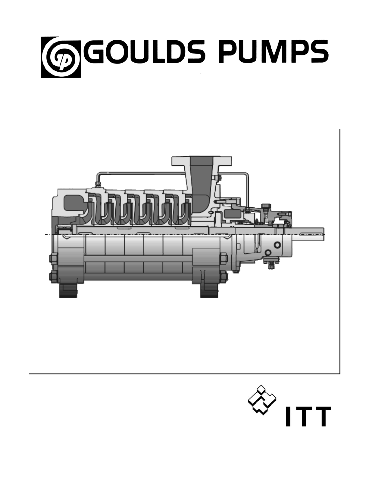
Installation, Operations, and Maintenance Instructions
Model 3311
Page 2

TABLE OF CONTENTS
PAGE SECTION
3 SAFETY INSTRUCTIONS 1
5 APPLICATION 2
7 SYSTEM LAYOUT 3
12 UNPACKING, HANDLING, STORAGE 4
14 PUMP INSTALLATION 5
17 STARTING AND STOPPING PROCEDURES 6
19 MAINTENANCE, DISASSEMBLY, ASSEMBLY 7
30 LOCATING TROUBLES 8
31 SECTIONAL DRAWING / PARTS LIST 9
Please note: Only trained and skilled operating personnel are allowed to install and operate this
pump or pump set. Compliance with these operating instructions and all applicable
rules and regulations must be ensured.
If you fail to comply with these operating instructions:
• people may be put at risk
• the pump or pump set may be damaged
• the manufacturer shall not be held liable for damage caused by non-compliance.
2
Page 3
1 Safety Instructions
1.1 Safety instructions
This manual gives basic instructions which must be
observed during installation, operation and maintenance
of the pump.
It is therefore imperative that this manual be read by the
installer and the responsible personnel or operators prior
to installation and commissioning. It must always be
available on site.
Within this manual, safety instructions are marked with
safety symbols.
Safety symbol to ISO 3864-B.3.1
This general hazard symbol highlights information noncompliance with which could cause a risk to personal
safety.
Safety symbol to ISO 3864-B.3.6
This symbol refers to electrical hazards.
CAUTION
This word gives warning of a hazard to the machine.
Signs affixed to the machine, e.g.
- arrow indicating the direction of rotation
- symbols indicating fluid connections
must be visible and kept legible.
1.2 Qualification and training of
operating personnel
The personnel responsible for operation, maintenance,
inspection and assembly must be properly trained and
qualified.
The responsibilities of the operating personnel must be
exactly defined by the plant operator. If the staff does not
have the necessary knowledge, they must be trained and
instructed, which may be performed by the machine
manufacturer or the supplier on behalf of the plant
operator, if required. Moreover, the plant operator is to
make sure that the contents of this manual are fully
understood by the operating personnel.
1.3 Hazards in the event of non-
compliance with the safety
instructions
Non-compliance with the safety instructions may cause a
risk to personnel as well as to the environment and the
machine. Non-compliance may result in a loss of any
right to claim damages.
For example, non-compliance may involve the following
hazards:
- failure of important functions of the equipment;
- failure of specified maintenance and repair procedures;
- electrical, mechanical and chemical hazards affecting
personal safety;
- leakage of environmentally damaging substances.
1.4 Safety at work
When operating the pump, the safety instructions
contained in this manual, the relevant national accident
prevention regulations and any other service and safety
instructions issued by the plant operator must be
observed.
3
Page 4

1.5 Safety instructions relevant to
operation
- If hot or cold machine components involve hazards, the
customer must ensure these components are guarded
against accidental contact.
- Guards for moving parts (e.g. coupling) must not be
removed from the machine while in operation.
- Any leakage of hazardous (e.g. explosive, toxic, hot)
fluids (e.g. from the shaft seal) must be drained away
so as to prevent any risk to personal safety or the
environment. Statutory regulations must be complied
with.
- Hazards resulting from electricity must be prevented.
Local regulations must be complied with.
1.6 Safety instructions relating to
maintenance, inspection and assembly
work
It shall be the plant operator's responsibility to ensure that
all maintenance, inspection and assembly work is
performed by authorized and qualified personnel who
have adequately familiarized themselves with the subject
matter by studying this manual in detail.
Any work on the machine shall only be performed when it
is not operating and has been properly secured from
starting. Always lock out power to the driver before
performing pump maintenance. The procedure for
stopping the machine described in this manual must be
followed.
Pumps which handle hazardous fluids must be
decontaminated.
On completion of work all safety and protective
equipment must be re-installed and made operative again.
Prior to restarting the machine, the instructions listed
under sub-section 6.4 "Checks before first start-up" must
be observed.
1.7 Unauthorized alterations and
production of spare parts
Any modification to the machine is permissible only after
consultation with Gould’s Pumps.
Using genuine spare parts and accessories authorized by
the manufacturer is in the interest of safety. Use of other
parts may exempt the manufacturer from any liability.
1.8 Unauthorized use
Goulds Pumps, inc. will not be liable for any damages or
delay caused by failure to comply with the provisions of
this instruction manual. The pump is not to be operated at
speeds, working pressures, discharge pressures or
temperatures higher than, nor used with liquids other than,
stated in the original order acknowledgement or the
conditions of service for which it was quoted without
written permission from Goulds Pumps.
4
Page 5
2 Application
2.1 Limitation of use
Operation of the pump must be limited to the application
and operating conditions stated by the purchaser and
confirmed on the manufacturer's data sheet. The pump is
covered by warranty under Gould’s Pumps’ conditions of
sale.
2.2 Wrong use
• Operate the pump only for the application stated on
the data sheet. Operation outside these limits of
product application will increase the risk to personal
safety and the environment.
CAUTION
• Do not exceed the density stated on the data sheet as
this could cause a motor overload condition.
• Do not operate the pump outside its characteristic
curve so as to avoid pump or motor damage.
2.3 Accessories
The accessories supplied with the pump are indicated on
the data sheet. Other accessories may be mounted to the
pump or the pump set only after Gould’s Pumps' prior
consent.
2.4 Design and working principle
The 3311 high pressure pump of the Goulds multi-stage
line is a horizontal multi-stage ring-section type
centrifugal pump.
It meets the technical requirements according to DIN ISO
5199 / EN 25199.
The pump casings are held together by external tie bolts
and sealed against the atmosphere by O-rings.
The axial thrust is balanced by a hydraulic balancing
device consisting of a disc/drum combination. An
additional lift-off device is available and intended for
special applications. The balancing liquid flows back
through an external line to the suction casing.
Suction nozzle: axial or radial.
In the case of radial suction nozzle orientation, the suction
casing pump feet assembly allows adaptation to the
installation requirements by rotating the casing.
Bearings:
Oil-lubricated anti-friction bearing on the discharge side;
suction side sleeve bearing lubricated by the liquid
handled or oil-lubricated anti-friction bearing.
Shaft seal:
Packed stuffing box or mechanical seal according to DIN
24960.
Drive:
Depending on its design, the pump is either driven from
the discharge side or the suction side, by a customary
electric motor or turbine. The direction of rotation is
counter-clockwise for discharge side drive, and clockwise
for suction side drive, when viewed from drive end.
2.5 Applications
- M unici pal water supply:
Pumping stations, treatment plants, booster units.
- Water treatment:
Filtration, reverse osmosis.
- Pumps for industrial purposes:
General water supply, cold water, boiler feed
installations, hot water, pumping of organic and
inorganic solutions, high-pressure gas washing; power
water generation plants, purifying and cleaning plants,
desalinization plants.
- Power supply:
Small and medium-sized thermal stations, waste
incineration installations.
5
Page 6
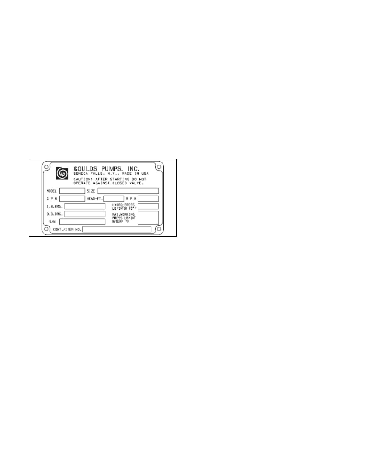
2.6 Nameplate Information
Every pump has a Goulds nameplate that provides
information about the pump. The tags are located on the
pump casing.
When ordering parts, you will need to identify the pump
model, size, serial number, and the item number of the
required parts. Information can be taken from the pump
casing tags. Item numbers can be found later in this
manual.
Pump Casing Tag – provides information about the
pump’s hydraulic characteristics. Note the format of the
pump size: Discharge x Suction – Nominal maximum
Impeller Diameter in inches.
(Example: 2x3-7)
6
Page 7
3 System Layout
3.1 Pipework
3.1.1 General
In short discharge lines, the nominal diameter should be
such that the piping resistance is only a small proportion
of the discharge head. For long pipelines, the most costeffective solution should be determined on a case-by-case
basis.
Flow velocity guidelines:
Suction line: v
max. 3 m/s
Discharge line: v
Abrupt cross-section transitions or sharp bends should be
avoided. Flow disturbances must be kept to a minimum
when making necessary branches.
Unfavorable pipework layouts may impair the
performance of the pump, especially on the suction side
(e.g. bends in several planes in front of the suction
nozzle).
≈ 1.5 to 2.5 m/s
s
≈ 4 to 6 m/s
D
• The pipework must be independently supported and
positioned such that no excessive forces and moments
are exerted on the pump flanges.
• Excessive loads could result in leakage and be
hazardous to personnel.
CAUTION
• If hot water is handled, excessive pipework loads and
moments can cause a misalignment of the coupling
between pump and driver, thus reducing the operating
safety of the unit.
Once the flange bolts have been released, the flanges must
not yield more than the amount corresponding to the
gasket thickness, nor must they be out of parallel nor bear
against each other under stress. Check that the flange
gaskets do not extend into the interior of the pipe. All pipe
components, valves and fittings and the pump nozzles
should be thoroughly cleaned before assembly.
Air-relief valves and drain valves must be installed in the
suction and discharge lines.
In order to prevent the formation of air pockets,
- a feed line (supply source above the pump) should
slope gradually downward towards the pump;
- a suction line (supply source below the pump) should
gradually rise to the pump.
Shut-off valves must be installed in the suction and
discharge lines and in all pipelines connecting the pump
with the liquid system.
The valves enable the pump to be depressurized and
dismantled without having to drain the system. Flow
regulation at constant speed is permissible from the
discharge side only.
CAUTION
• The pipes should have at least the nominal diameter of
the pump nozzles. Where this is not possible, it should
be ensured that the flow velocity in the suction or feed
line does not exceed 2 - 3 m/s.
• Flange seals must not extend into the interior of the
pipework.
• Clean the pipework prior to pump installation.
• Support the pipelines so as to prevent distortion of
pump components.
• Avoid rough cross-section transitions and sharp bends.
• Eccentric reducers must be used in the event of
different nominal diameters.
• In the event of unfavorable suction conditions, stead y
flow should be ensured over a length of 15 x suction
nozzle diameter upstream from the suction nozzle.
• Shut-off valves in the suction or discharge line must
be fully open during operation and must never be
used to control the flow.
7
Page 8
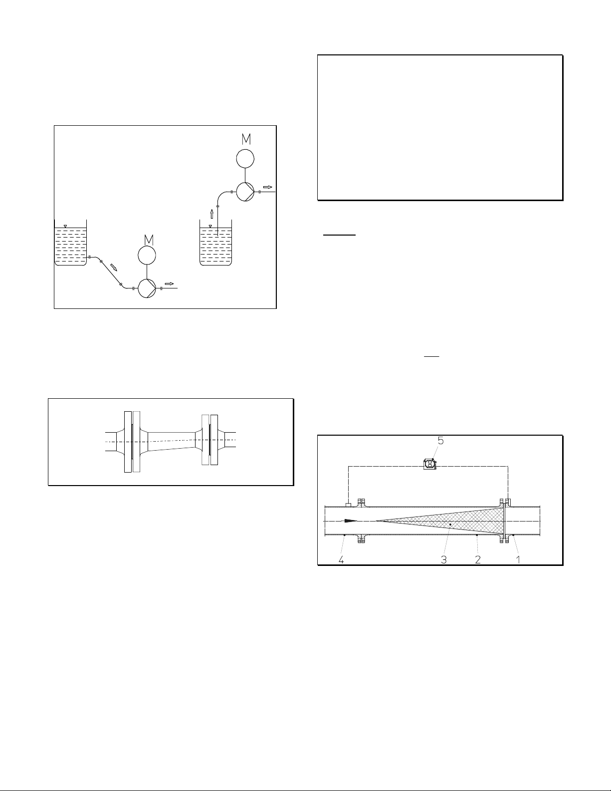
3.1.2 Suction or feed line
A suction line should rise to the pump and a feed line
should slope gradually downward towards the pump.
Feed operation suction operation
Reducers mounted must be eccentric to eliminate the
possibility of air pockets being formed.
CAUTION
• The strainer is for starting purposes only. Solids which
are smaller than the mesh size will not be retained by
the strainer.
• However, such small particles may collect in the
lateral area of the impeller near the clearances, in
particular if their concentration is high.
• In order to prevent clogging, it is recommended that
the customer provide a sedimentation tank or a larger
flushable fine strainer upstream from the pump.
Design:
Conical strainer with perforated plate support body with
external fine screen, mesh size 0.5 mm, of corrosionresistant material. The fine screen can be removed after
several months of operation, once there are no more
deposits.
For new conical strainers supplied by Gould’s Pumps the
pressure loss can be calculated as follows:
Hv
2
v
ζ
•=
g2
in m
v = medium flow velocity in reference cross-section,
in m/s
ζ = 4, loss coefficient for new conical strainers
Eccentric reducer
If the liquid is contaminated, a filter should be fitted
upstream from the pump whose free-space sectional area
should be three times the pipe cross-sectional area.
8
1 Pump suction nozzle / flange
2 Pipe section for strainer
3 Conical strainer
(installed with its tip against flow direction)
4 Feed line
5 Differential pressure measuring instrument
Feed line with conical strainer
Page 9
Determining the strainer pressure loss
Example:
Feed line = DN 125
Flow rate 80 m³/h
ζ = 4
v = 1.81 m/s in the feed line
Hv =
2
4
81.1
•
81.92
•
276.3
4
62.19
66.0
=•=
m
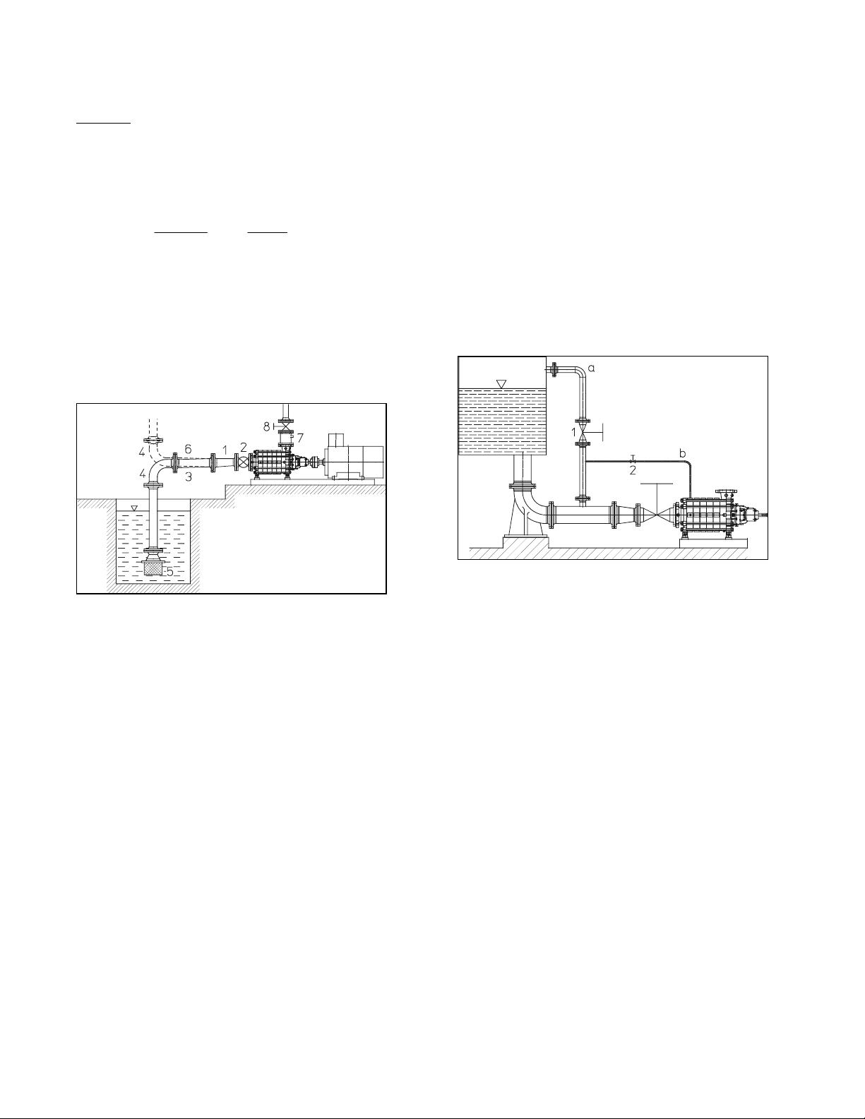
The suction line must be leak-proof and it must be
possible to release all air. The suction opening of the
suction line should be well below the liquid level, and a
foot valve with a strainer should be used. The foot valve
must be far enough from the bottom to avoid excessive
inlet losses which could impair performance.
3.1.3 Vacuum equalizing pipe
If the pump draws from a system or tank under vacuum,
an equalizing pipe must be installed connecting the vent
connection at the suction casing or the highest point of the
suction line to a point above the maximum liquid level in
the suction tank.
- The line should be fitted with a shut-off valve which
should only be closed for maintenance work on the
pump.
To assist in starting the pump, we also recommend that a
pipeline, which can be shut off, be installed between the
first stage and the equalizing line.
1 Eccentric reducer (suction operation) or
concentric reducer (feed operation)
2 Shut-off valve
3 Suction line
4 Bend
5 Foot valve
6 Feed line
7 Non-return valve
8 Control valve
Pump installation
A shut-off valve should be installed in the feed line; it is
to be closed for maintenance work.
It should be installed such that air pockets cannot form in
the spindle cap, i.e. with the spindle in a horizontal
position or pointing vertically downward.
a Equalizing line
b Additional line
1 Shut-off valve
2 Shut-off valve (vacuum-tight)
Vacuum operation
3.1.4 Discharge line
For flow control, install a shut-off valve as close to the
pump nozzle as possible. It is recommended that a nonreturn valve be installed between pump nozzle and shutoff valve, thus protecting the pump against reverse
rotation and also the pump and the foot valve against
water hammer that may occur in the event of sudden shutdown.
9
Page 10
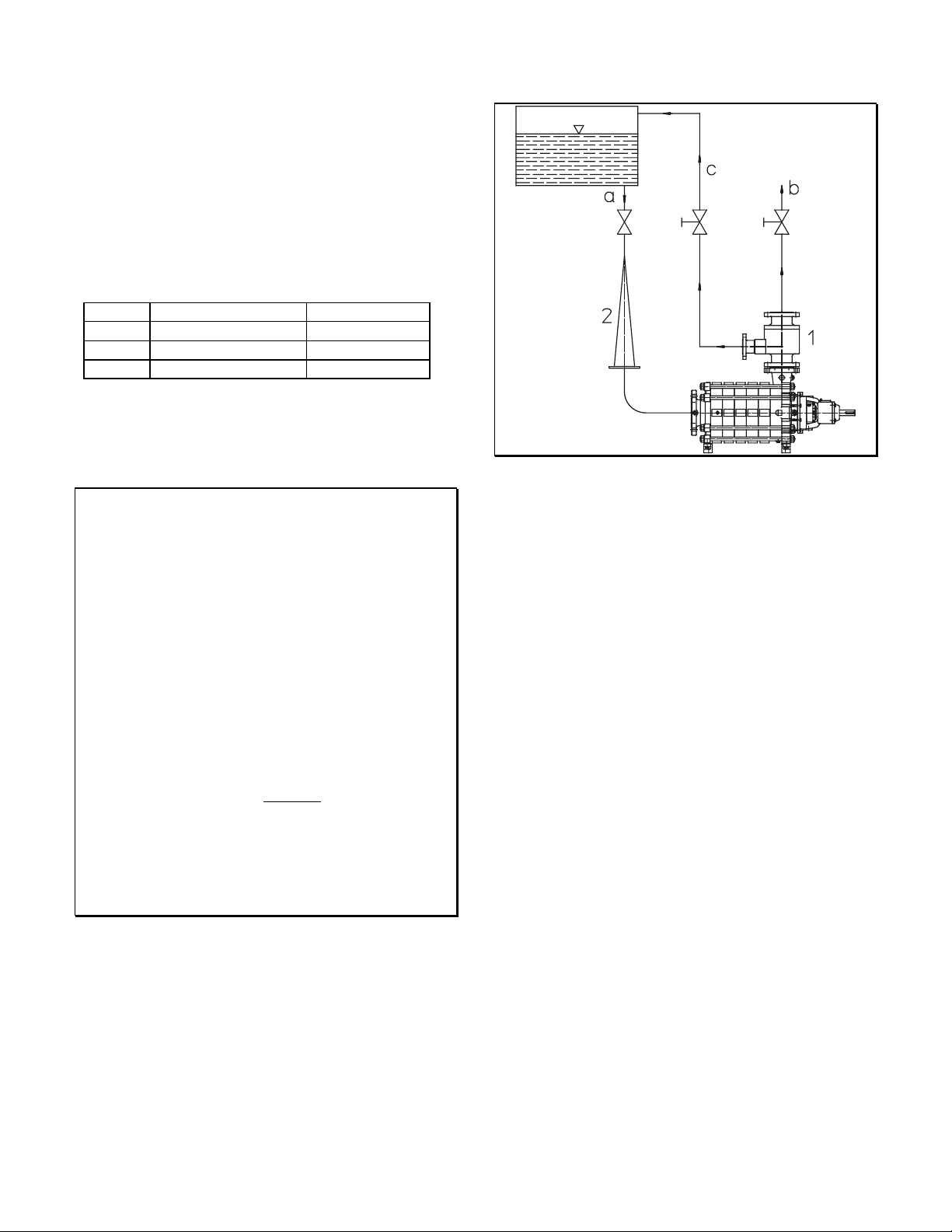
3.1.5 Minimum flow line
The minimum flow line (or bypass line) should be used if
operation with the discharge side shut-off valve closed is
possible. The minimum flow valve ensures that a
sufficient rate is automatically returned to the suction side
tank.
The minimum flow rate is shown on the curves or the data
sheet.
Size t = 140 °C or lower t > 140 °C
2x3-7 20 % of Q
2.5x4-8 20 % of Q
4x5-11 25 % of Q
25 % of Q
BEP
25 % of Q
BEP
25 % of Q
BEP
BEP
BEP
BEP
Should exact calculation be required, please contact
Gould’s Pumps.
CAUTION
• Up to the shut-off or non-return valve, the line should
be designed to suit the nominal pressure of the
discharge line, afterwards in accordance with the
design pressure of the feedwater/suction tank.
• Permissible velocity in the minimum flow line: 7 to 10
m/s.
• If an automatic device (bypass non-return valve) is
used, ensure that even in the case of trouble, liquid can
be returned through the minimum flow line.
• Frequent checks are recommended. Early replacement
of the minimum flow valve (which is exposed to
heavy wear) will prevent energy losses.
• The minimum flow valve should be installed near the
pump discharge nozzle, upstream from the discharge
shut-off valve.
• A non-return valve should be installed in the
minimum flow nozzle or the minimum flow line.
• For repair or overhaul work on the pump or the bypass
non-return valve, a shut-off valve must be installed in
the minimum flow line (c).
a Feed line
b Discharge line
c Bypass line
1 Bypass non-return valve
2 Conical strainer
Minimum flow control
3.1.6 Balancing line
The balancing line connects the discharge side shaft
sealing casing with the suction casing. There is no
throttling or shut-off device in this line, which serves to
hydraulically balance the pump.
The balancing line can also be returned by the customer to
the feed tank or the feed line.
3.1.7 Venting during pump priming
Before starting the set, the pump and the suction line must
be completely vented and filled with the liquid handled.
To bleed the air, several holes with plugs have been
provided. Similar holes may be used in the pip ework. The
shut-off valve in the suction or supply line must be fully
open.
10
Page 11

3.1.8 Cooling
Cooling is required if the temperature of the liquid
handled exceeds 110 °C, if a packed stuf fing box is used,
or 140 °C if a mechanical seal is installed. For this
purpose the pump is equipped with a shaft sealing casing
which can be cooled. The connecting points for the
cooling lines are on the shaft sealing casing. The customer
should provide either an open circuit, i.e. a cooling water
return line to the drain system, or a closed circuit
including a return to the cooling circuit to be provided.
3.1.9 Drain line, leakage water line
The pump has connections for leakage water and drain
lines.
3.1.10 Pressure monitoring
In order to monitor the pressures upstream and
downstream from the pump, the installation of measuring
points in the pipeline is recommended.
3.2 Electrical connections
The electrical connection for the driving motor must be in
compliance with the relevant rules and requirements.
11
Page 12
4 Unpacking, Handling, Storage
4.1 Safety measures
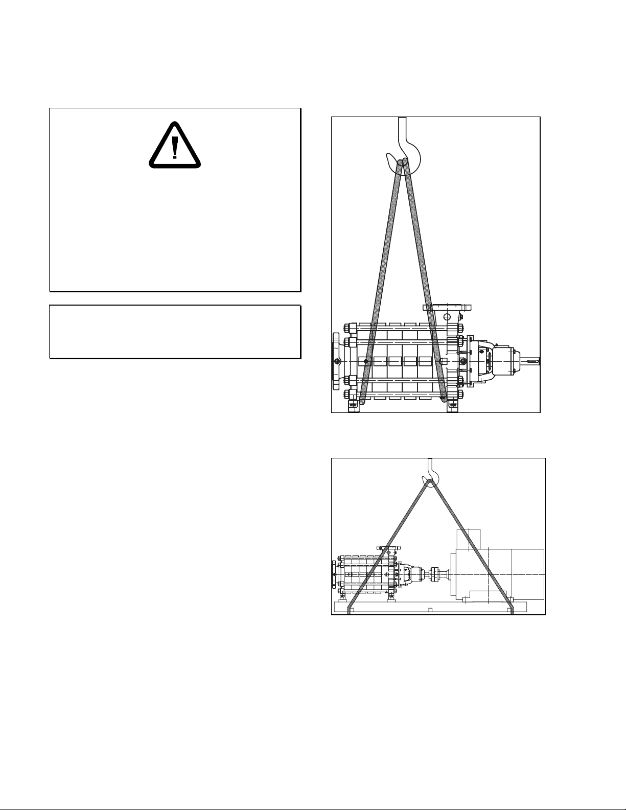
4.4 Handling
The pump or the pump set must be lifted as shown below:
• Do not lift heavy equipment overhead of personnel.
• A safe distance must be kept when lifting and moving
the equipment.
• Use only approved and suitable lifting equipment.
• The length of the lifting equipment should be such
that the pump or the set are lifted in horizontal
position.
• Do not attempt to lift the pump or the pump set using
eyebolts on pump components.
CAUTION
• Do not remove protection covers from the pump
nozzles, as they prevent contamination of the pump.
4.2 Unpacking
Do not unpack the pump until it has been carefully
checked for damage that may have occurred in transit.
Report any damage on the counterfoil or delivery note.
Claims must be made immediately on the carrier or the
transport insurance.
4.3 Intermediate storage
If the pump or the pump set is not to be installed
immediately it should be stored in a clean, dry and
vibration-free room.
The packing should be checked for damage on a monthly
basis.
Lifting the pump
Lifting the pump / motor / baseplate assembly
12
Page 13

4.5 Preservation
Usually, only iron pumps are preserved.
4.5.1 Removal of preservation
To remove the preservative coating, the pump should be
filled and drained several times using appropriate agents,
e.g. solvent naphta, diesel oil, or an alkaline detergent.
Flush with water, if necessary.
The pump must be installed and put into operation
immediately afterwards.
4.5.2 Re-preservation
If the pump has been supplied preserved and is to be
stored, a new preservative coating should be applied after
six months.
For suitable preservatives, contact Goulds Pumps.
13
Page 14
5 Pump Installation
5.1 Prerequisites
Prior to the installation of the pump, the storage and
handling instructions in Section 4 must have been
complied with.
5.2 Safety measures
• The pipework must be properly installed. Fluid
leakage during operation may cause health hazards or
environmental damage.
• The shut-off valves in the suction or feed line and in
the discharge line must be closed.
• All internal rules and guidelines must be complied
with.
• Hot components must have contact guards.
• Disconnect power to the equipment so as to eliminate
electrical shock hazards!
5.3 General
5.3.1 Fitting tools
Standard tools and lifting equipment are used. These
should be available at the customer's end.
5.3.2 Permissible environment
The ambient temperature range should be from
- 20 °C to + 60 °C.
The atmospheric humidity should be low in order to avoid
corrosion.
5.3.3 Space utilization
The space required by the pump or the pump set can be
seen from the table of dimensions and the arrangement
drawing.
Clear and easy access to the shut-off and regulating
valves and the measuring instruments must be ensured.
5.3.4 Installation position
3311 pumps are installed in horizontal position.
5.3.5 Preparatory checks
The foundation of the pump must be level and have a
minimum of vibration. The consistency of the concrete
should at least correspond to BN15, DIN 1045.
We recommend using a baseplate.
Prior to installation checks should be made with regard to:
- possible damage to the pump or the pump set that may
have occurred in transit
- ease of running (check that the shaft is free to rotate by
hand)
- the foundation dimensions.
5.3.6 Foundation
Prior to placing the pump set on the foundation which
should be well set, the following preparatory work must
be carried out:
- roughen and clean foundation surface
- remove shuttering/cores from the anchor holes
- clean and blow out the anchor holes
- check the positions and dimensions of the anchor holes
against the arrangement drawing.
Alternatively:
If the baseplate is fastened by means of heavy load plugs:
- Scribe and drill plug holes
- Clean plug holes and blow them out
- Inse rt heavy l oad plugs
14
Page 15

5.3.7 Installation of the set
4
The complete set mounted on the baseplate must be
placed on the foundation with its foundation bolts
suspended. If heavy load plugs are used, first screw in the
threaded rods in the plugs.
5.4 Motor
Prior to assembly the direction of rotation of the motor
must be checked (arrow on pump bearing housing).
5.5 Alignment of the set
- Place shims under the baseplate on both sides of the
foundation bolts (see Fig.).
- Use a spirit level to align the set.
- If the foundation bolts are more than 800 mm apart,
place additional shims between the foundation bolts to
prevent the baseplate from sagging. Care should be
taken to minimize distortion of the baseplate during
installation.
- The foundation bolts should be embedded in concrete
using quick-setting grout (this is not required if heavy
load plugs are used).
- Tighten the nuts of the foundation bolts in diagonal
sequence (after the grout has set).
- Re-check alignment with a spirit level.
Carry out the radial alignment of the coupling using a
knife-edge straight-edge and a feeler gauge.
1
Required dimensions:
a=a1 and b=b1, tolerance: ± 0.05 mm
1 knife-edge straight-edge
Aligning the coupling
The pumps are designed for high temperature foot
fastening as standard. Therefore, the pump feet must not
be fixed to the baseplate in order to avoid distortion
caused by high temperatures of the liquid handled and the
resulting expansion of the pump casing.
Stud bolts (1) and adjusting nuts (2) are used for the high
temperature foot fastening. Install adjusting nut (2) and
turn it finger-tight only (do not use a wrench), thus
installing the washer (3) free from play; however, the
washer (3) should still be movable by light hammer taps.
Lock the adjusting nut (2) in its position by tigh tening the
safety screw (4).
112 3
1
2
1 Shims
2 Additional shim, if foundation bolt distance ≥ 800 mm
Position of the shims
After aligning the set the axial clearance between the two
coupling halves measured at one point of the coupling
must be the same over the complete circumference of the
coupling, the permissible tolerance being ± 0.05 mm.
1 Stud bolt 3 Washer
2 Adjusting nut 4 Safety screw
15
Page 16

Guide pins (6) on the suction and discharge casing feet
prevent lateral movement of the pump. The drive side
guide pin is held in place by a guide casing which is
bolted to the baseplate (8). The opposite guide pin can
move in a guide casing.
5 Guide casing
6 Guide pin
7 Pump foot support
8 Baseplate
CAUTION
• Avoid distortions when finally tightening the bolts.
• The nuts of the foot fastening must be loosened so far
that the washers can be moved by light hammer
blows.
5.6 Grouting the baseplate
Prior to grouting the baseplate, carry out the following
preparatory work:
- Check the dimensions with regard to height and
alignment of flanges.
- Re-adjust baseplate, if necessary.
Ram earth-humid concrete under the baseplate or add
shrinkage-free grout until the entire space under the
baseplate is filled. Grouting should be a continuous
process so as to ensure that no air pockets form under the
baseplate.
When the grout is set re-tighten the foundation bo lts and
re-check the alignment of the coupling.
5.7 Pump installation in the piping system
CAUTION
• The pipework forces and moments acting on the pump
nozzles must not exceed the permissible pump nozzle
loads.
• The pump must not be used to clean the pipework
with chemicals.
- Remove the protection covers from the pump flanges
and the auxiliary pipeline connections.
- Insert the flange gaskets.
- Connect the suction or feed line.
- Connect the discharge line.
5.8 Hydrostatic test
• If the piping system is to undergo a hydrostatic
pressure test, the pump must be excluded from such
testing.
5.9 Cleaning, flushing and pickling of the
pipework
When the pipework is cleaned, flushed or pickled, the
pump must be excluded.
16
Page 17

6 Starting & Stopping Procedures
6.1 Prerequisites
The pump or the pump set must have been installed in
accordance with the instructions of Section 5.
6.2 Safety measures
• If there is no shaft seal, interrupt all further work and
install a shaft seal. Priming the pump with the liquid
handled in the absence of a shaft seal may present a
human-health or environmental hazard.
• Ensure that people and the environment are not put at
risk through explosive, toxic, hot, crystalline, or acid
liquids handled.
• Be sure that all electrical connections comply with the
local rules and regulations and that this work is done
by authorized personnel only.
CAUTION
• Fill bearing housings with oil.
• The pump must be completely primed and vented.
• Check the direction of rotation only with the pump
primed.
• If the liquid handled is hot, the pump should be filled
slowly so as to avoid distortions or heat shocks.
• The flow rate should be changed at constant speed
only on the discharge side. During operation the
regulating valve in the suction or feed line should
always be fully open.
• Do not run the pump with the regulating valve closed
for more than 30 seconds, if there is no minimum flow
bypass line.
• Safety measures should be taken at the customer's end
to ensure (for example by means of a relief valve) that
the permissible pump casing pressure is not exceeded
during operation.
• Repeat the alignment of the coupling at operating
temperature. Re-align the pump or the motor, if
necessary.
6.3 Electrical connection
Connect the electrical supply to the motor in accordance
with the connection diagram in the terminal box.
6.4 Checks before first start-up
- Are the pipelines connected and are the flange
connections tight?
- Is the pump incl. the pipework correctly primed?
- Is the shut-off valve in the discharge line closed?
- Is the shut-off valve in the suction or feed line fully
open?
- Is the motor ready?
- Is the direction of rotation of the motor correct? (Check
by momentarily switching on the motor.)
- Is the coupling correctly aligned (see Section 5)?
- Can the washers of the foot-fastening be moved? (see
subsection 5.5)
- Has the shaft seal been installed?
- Are the supply lines, if any, to the shaft seal open?
- Has the bearing housing been correctly filled with oil?
(see subsection 7.3.1).
CAUTION
• If the discharge pressure does not rise steadily as the
speed increases, stop the motor and re-vent and refill
the pump.
• Do not switch the pump on and off more often than
ten times per hour (this applies to a max. density of
1000 kg/m³ of the liquid handled). The motor
manufacturer's instructions must be followed.
17
Page 18

6.5 Starting procedure
- Check everything using the check list of sub-section
6.4.
- Switch on the motor.
- Check the pressure gauges at the pressure measuring
points.
- Open the discharge side regulating valve to adjust the
duty point of the pump.
CAUTION
• A fluid quantity of a few cm³ per hour will typically
leave the mechanical seal in the form of vapor, mist or
droplets. If there should be a considerable increase in
the leakage rate after the start-up phase, stop the pump
and check the mechanical seal.
• If a stuffing box is installed, the leakage rate after
start-up should be higher than during operation. After
about 1 hour, tighten the gland nuts gradually until
there is a slight drop leakage.
6.6 Particular information
The following parameters should be monitored during
operation:
- power consumption of the motor
- smoothness of pump operation (no vibrati on)
- bearing temperature
- leakage
6.7 Stopping procedure
- Cl ose the discharge side regulating valve.
- Switch off the m otor.
- Once the pump is at rest, close the shut-off valves of
the feed line and cooling line (if installed).
CAUTION
• If there is danger of freezing, the pump should be
drained down.
• Please note that there will always be some residual
liquid even if the pump is emptied in vertical position.
• Ensure that the pump does not contain any hazardous
substances when it is dismantled to be returned to the
manufacturer's factory.
• Ensure that during prolonged inactivity the pump is
operated for about five minutes every 1 to 3 months.
Follow the instructions under 6.5.
18
Page 19

7 Maintenance, Disassembly, Assembly
7.1 Prerequisites
The pump or the pump set must have been taken out of
operation in accordance with the instructions of Section 6.
7.2 Safety measures
Standard design with constant level oiler
- Pull oil bottle out of the screw-in elbow.
- Fill the bearing housing with oil until the oil becomes
visible in the screw-in elbow.
- Fill oil bottle through filler hole.
- Replace oil bottle. As long as there is oil in the bottle
the oil level in the bearing housing is sufficient.
• Flush the pump thoroughly before disassembly to
purge away the residual liquid left after draining the
pump.
• Ensure that people and the environment are not put at
risk through explosive, toxic, hot, crystalline, or acid
liquids handled.
CAUTION
• The workplace for disassembly or assembly must be
clean.
7.3 Maintenance and inspection
7.3.1 Oil-lubricated bearings
If the driver is on the discharge side, the pumps will be
equipped with oil-lubricated anti-friction bearings on the
drive side and a sleeve bearing lubricated by the liquid
handled on the suction side. If the driver is on the suction
side, the pump will have an oil-lubricated anti-friction
bearing on the suction side. An additional oil-lubricated
anti-friction bearing will be mounted on the discharge
side of pumps equipped with a lift-off device.
Pumps are shipped from the factory without oil in the
bearing housings.
The bearing housings must be filled with oil befo re initial
start-up.
CAUTION
• Use only very clean and non-ageing oil with good
water separating and corrosion protection properties.
If the bearings are new, change first oil after about 200
operating hours. Afterwards, change the oil in accordance
with the following table:
light service normal and severe service
Light contamination,
T < 50 °C
Annually every six months
Use the following lubricating oils:
Bearing temperature
< 80 °C
Lubricating oil acc.
to DIN 51517
Kin. viscosity
at 40 °C in mm²/s
Neutralization
number
Ash content,
weight-%
Water content,
weight-%
Oil consumption (l)
Size Lift-off device
without with
2x3-7 0.19 0.25
2.5x4-8 0.24 0.30
4x5-11 0.27 0.35
n ≤ 1500
rpm
CL 68 CL 46 CL 22
61.2 to
74.8
light contamination,
T > 50 °C
Ambient
temperature
< 0 °C
n > 1500
rpm
41.8 to
50.8
≤ 0.15 mg KOH/g
≤ 0.02
≤ 0.1
19.8 to 24.2
19
Page 20

7.3.2 Mechanical seal
Generally, virtually no maintenance is required on
mechanical seals. The mechanical seal should exhibit only
light visible leakage. In the case of heavy leakage, the
mechanical seal should be checked (see Section 6.6).
7.3.3 Packed stuffing box
With a packed stuffing box, there is always a leakage in
the form of drops. In the case of heavy leakage, the
packing and the shaft wearing sleeve should be checked
(for scores).
7.3.4 Driving motor
Maintenance of the driving motor should be in
compliance with the manufacturer's instructions.
7.4 Disassembly
Operating troubles involving pump disassembly are
unlikely in the event of careful monitoring and
maintenance of the pump.
However, if trouble occurs, the reason should be found
before disassembly, if possible. Repair and overhaul work
should be carried out by Goulds Pumps personnel or the
pump should be inspected at the manufacturer's factory.
Please note that any disassembly work to be performed
during the warranty period requires the approval of
Goulds Pumps.
If you disassemble the pump, all components should be
treated with utmost care.
All parts must be cleaned carefully, checked for wear and
reconditioned or replaced by spare parts, if necessary. It is
vital that the shaft is checked for concentricity. Use only
genuine spare parts.
7.4.1 Preparation for disassembly
- Disconnect power to the motor.
- Drain the system between suction side and discharge
side shut-off valves.
- Disconnect and dismantle existing sensors and
monitoring devices, if necessary.
- Dismantle coupling.
- Drain the liquid from the pump.
- Dismantle shaft seal supply lines, if any.
- Unbolt the pump from the pipe work.
- Dismantle balancing line.
- Drain the oil from the bearing housings.
7.4.2 Replacement parts
For re-assembly, replace all O-rings.
The item numbers of replacement parts are given in the
components list, section 9.
20
Page 21

7.4.3 Disassembly of the pump
Mark positions and sequence of the parts with a colored
pen or a scriber, for later re-assembly.
Measure and record shaft projection to bearing cover
(dimension X, section 7.6.2.2).
7.4.3.1. Discharge side drive
7.4.3.1.1. Dismantling of the bearings
a) Sleeve bearing, lubricated by the liquid handled
(non-drive side)
Axial suction nozzle
- R emove bearing cover 160.1
- Remove circlip 932.1
- Pull out bearing bush 545.1/545.2 with O-rings 412.1
- Remove bearing sleeve 529.1
CAUTION
• Anti-rotation grooved pin 561.1 must remain in the
shaft.
Radial suction nozzle
- Release hexagon head bolts 901.2
- R emove bearing cover 160.1 with O-rin g 41 2. 11
- Remove circlip 932.1
- Pull out bearing bush 545.1/545.2 with O-rings 412.1
- Remove bearing sleeve 529.1
CAUTION
• Anti-rotation grooved pin 561.1 must remain in the
shaft.
21
Page 22

b) Anti-friction bearing,
- oil-lubricated – drive side
- without lift-off device -
- If installed - remove cooling and/or circulation line
- R emove key 940.5
- Release bolts 914.5
- Remove bearing cover 360.1 with labyrinth ring 423.2
and limiting ring 380
- Release grub screw 904.2
- Remove circlip 932.2
- Support shaft 210 and key 940.5, and release shaft nut
921
- Release bolts 914.2
- Withdraw bearing housing 350.1, labyrinth ring 423.1,
bearing 322 and bearing sleeve 529.2
- R emove key 940.4
c) Anti-friction bearing,
- oil-lubricated - drive side
- with lift-off device -
- If installed - remove cooling and/or circulation line
- R emove key 940.5
- Remove suction side bearing cover 160.1 as described
under a) for axial or radial suction nozzle
- Fix shaft 210 axially on the suction side
- Release bolts 914.5
- Remove bearing cover 360.1 with labyrinth ring 423.2
and limiting ring 380
- Compress spring 950 by moving bearing carrier 382
- Remove circlip 932.3
- R emove bearing 321
- Release bolts 914.4
- Remove bearing housing 350.2 with bearing carrier
382 and spring 950
- Release grub screw 904.1
- Release bearing sleeve 529.3
- Remove circlip 932.2
- Pull spacer sleeve 525 from shaft 210
- Release bolts 914.2
- Withdraw bearing housing 350.1, labyrinth ring 423.1,
bearing 322, bearing sleeve 529.2
- R emove key 940.4
7.4.3.1.2. Dismantling of shaft seal
a) Stuffing box packing
22
Dismantle bearings in accordance with 7.4.3.1.1 b) or c)
- Release nuts 920.2
- Sli de bac k the st uf fi n g box gland 452
- Remove packing rings 461
- Remove balancing line
- Release bolts 914.1
- Dismantle sealing casing 441
- Withdraw shaft wearing sleeve 524
b) Mechanical seal
Page 23

7.4.3.1.4. Dismantling of hydraulic unit
Dismantle bearings in accordance with 7.4.3.1.1 b) or c)
- Release nuts 920.2
- Remove seal cover 471
- Remove balancing line
- Release bolts 914.1
- Withdraw sealing casing 441, mechanical seal 433 and
shaft sleeve 523
7.4.3.1.3. Dismantling of balancing device
Dismantle bearings in accordance with 7.4.3.1.1 b) or c)
Dismantle shaft seal in accordance with 7.4.3.1.2 a) or b)
Dismantle balancing device in accordance with 7.4.3.1.3
- R emove key 940.2
- Release nuts 920.1
- Remove tie bolts 905
- Support stage casing 108.1
- Dismantle delivery casing 107
- Remove, from stage to stage, impeller 230, key 940.1,
stage casing 108.1 with diffuser 171.1, in that order
Dismantle bearings in accordance with 7.4.3.1.1 b) or c)
Dismantle shaft seal in accordance with 7.4.3.1.2 a) or b)
- Pull balance disc 601 from shaft 210
- R emove key 940.3
- Dismantle balance disc seat 602
- Pull balance drum 603 from shaft 210
23
Page 24

7.4.3.2. Suction side drive
7.4.3.2.1. Dismantling the oil-lubricated anti-
friction bearing - drive side
7.4.3.2.2. Dismantling the shaft seal - drive side
a) Stuffing box packing
- If installed - remove cooling and/or circulation line
- R emove key 940.5
- Release bolts 914.7
- Dismantle bearing cover 360.1 with labyrinth ring
423.2
- Release grub screw 904.2
- Remove circlip 932.2
- Support shaft 210 and key 940.5, and release shaft nut
921
- Release bolts 914.2
- Withdraw bearing housing 350.1, labyrinth ring 423.3,
bearing 322 and bearing sleeve 529.2
- R emove key 940.4
Dismantle bearings in accordance with 7.4.3.2.1
- Release nuts 920.2
- Sli de bac k the st uf fi n g box gland 452
- Remove packing rings 461
- Release bolts 914.1
- Remove sealing casing 441
- Withdraw shaft wearing sleeve 524
b) Mechanical seal
24
Dismantle bearings in accordance with 7.4.3.2.1
- Release nuts 920.2
- Dismantle seal cover 471
- Release bolts 914.1
- Withdraw sealing casing 441, mechanical seal 433 and
shaft sleeve 523
Page 25

7.4.3.2.3. Dismantling of oil-lubricated anti-
friction bearing- non-drive side -
a) Without lift-off device
b) With lift-off device
- If installed - remove cooling and/or circulation line
- Release bolts 914.5
- Remove bearing cover 360.2 with limiting ring 380
- Release grub screw 904.2
- Remove circlip 932.2
- Support shaft 210 on the drive side with key 940.5, and
release shaft nut 921
- Release bolts 914.2
- Withdraw bearing housing 350.1, labyrinth ring 423.1,
bearing 322 and bearing sleeve 529.2
- R emove key 940.4
- If installed - remove cooling and/or circulation line
- Fix shaft 210 axially on the drive side
- Release bolts 914.5
- Remove bearing cover 360.2 with limiting ring 380
- Compress spring 950 by moving bearing carrier 382
- Remove circlip 932.3
- R emove bearing 321
- Release bolts 914.4
- Remove bearing housing 350.2 with bearing carrier
382 and spring 950
- Release grub screw 904.1
- Release bearing sleeve 529.3
- Remove circlip 932.2
- Pull spacer sleeve 525 from shaft 210
- Release bolts 914.2
- Withdraw bearing housing 350.1, labyrinth ring 423.1,
bearing 322 and bearing sleeve 529.2
- R emove key 940.4
25
Page 26

7.4.3.2.4. Dismantling of shaft seal- non-drive
side -
a) Stuffing box packing
Dismantle bearings in accordance with 7.4.3.2.3 a) or b)
- Release nuts 920.2
- Remove seal cover 471
- Remove balancing line
- Release bolts 914.1
- Withdraw sealing casing 441, mechanical seal 433 and
shaft sleeve 523
7.4.3.2.5. Dismantling of the balancing device
Dismantle bearings in accordance with 7.4.3.2.3 a) or b)
- Release nuts 920.2
- Sli de bac k the st uf fi n g box gland 452
- Remove packing rings 461
- Remove balancing line
- Release bolts 914.1
- Dismantle sealing casing 441
- Withdraw shaft wearing sleeve 524
b) Mechanical seal
Dismantle bearings in accordance with 7.4.3.2.3 a) or b)
Dismantle shaft seal in accordance with 7.4.3.2.4 a) or b)
- Pull balance disc 601 from shaft 210
- R emove key 940.3
- Dismantle balance disc seat 602
- Pull balance drum 603 from shaft 210
26
Page 27

7.4.3.2.6. Dismantling of hydraulic unit
Dismantle bearings in accordance with 7.4.3.2.3 a) or b)
Dismantle shaft seal in accordance with 7.4.3.2.4 a) or b)
Dismantle balancing device in accordance with 7.4.3.2.5
- R emove key 940.2
- Release nuts 920.1
- Remove tie bolts 905
- Support stage casing 108.1
- R emove delivery casing 107
- Remove, from stage to stage, impeller 230, key 940.1,
stage casing 180.1 with diffuser 171.1, in that order
7.5 Work after disassembly
- Clean all parts.
- Clean the clearances and sealing surfaces.
The following pump components, if existing, must be
checked:
Mechanical seal
If the running faces are damaged or worn, replace the
mechanical seal.
Clearances
The diameter difference between impeller clearance area
and casing or cover clearance area of a new pump is
between 0.3 and 0.6 mm, depending on size and material.
In the case of excessive wear in the clearance area, wear
rings must be installed.
Shaft
Carry out a concentricity check.
7.6 Assembly
CAUTION
• The assembly work must be based on good
engineering practice.
- Use no force.
- Heavy parts must be supported during assembly.
- Before assembly, apply a layer of an appropriate
erection substance on the fitting points. Observe
instructions with regard to cleanliness and safety.
- The properties of new pump components must not be
changed without our head office's consent.
- All parts must be clean and free from chips or dust.
- The unit may be re-assembled in the reverse manner to
disassembling.
- Observe the tightening torques specified.
- Quick-sticking glues are not permitted.
27
Page 28

7.6.1 Tightening torques
Size 2x3-7
No. of stages
Tightening
torque
Size 2.5x4-8
No. of stages
Tightening
torque
Size 4x5-11
No. of stages
Tightening
torque
≤ 12
710 Nm 850 Nm 900 Nm
≤ 8
610 Nm 920 Nm 980 Nm
≤ 4
790 Nm 1420 Nm 1570 Nm 1790 Nm
13 - 15 16 - 18
9 - 13 14 - 18
5 - 8 9 - 12 13 - 15
7.6.2 Pump assembly
- Installation starts on the suction side.
- The pump should be assembled in a vertical position, if
possible.
- Install the parts in their original position.
- Observe the sectional drawing with list of components.
- Lightly tighten the nuts of the tie bolts.
- Place pump on its feet, in horizontal position, on a flat
work surface.
- Tighten nuts of the tie bolts in several stages in
diagonal sequence (nominal tightening torque at last
stage).
7.6.2.1. Shaft seal
Packed stuffing box
CAUTION
• The packing rings must not be inserted until after the
pump, including the bearings, has been completely
installed.
- Only pre-compressed packing rings are permissible.
- Thoroughly clean the packing area and the stuffing box
gland.
- The first packing ring should now be laterally bent
open and pushed on the shaft wearing sleeve.
- Slide the packing ring into the packing chamber using
the stuffing box gland.
- Install the other packing rings in the same manner,
however with the gaps 180° apart.
- Tur n t he glan d nut s finger-tight.
- Check that the gland is not tightened at a slant.
CAUTION
• The pump rotating assembly must be free to rotate by
hand.
• The stuffing box leakage must not be adjusted until
start-up (see Section 6).
Dimensions Pump size
in mm 2x3-7 2.5x4-8 4x5-11
Packing cross-section 10 10 12.5
Number of rings 4 5
Shaft diameter 45 75 95
Mechanical seals
CAUTION
• Utmost care should be taken when mounting the
rotary and stationary seal rings so as to avoid
contamination and/or distortion on the sealing
surfaces.
• EPDM seals must not be exposed to oil or grease.
• In order to achieve the compression pressure required
for the operational reliability of the mechanical seal,
check the axial installation dimension against the
installation drawing.
- Install the mechanical seal in the reverse manner to
disassembling.
28
Page 29

7.6.2.2. Bearings
Discharge side drive
- Install sleeve bearing in the reverse manner to
disassembling.
- Install anti-friction bearing with or without lift-off
device in the reverse manner to disassembling.
Suction side drive
CAUTION
• Check axial position of the rotor. Dimension X must
be the same as before disassembly.
Install suction side anti-friction bearing in the reverse
manner to disassembling.
Install discharge side anti-friction bearing, without or with
lift-off device in the reverse manner to disassembling.
CAUTION
• Check axial position of the rotor. Dimension X must
be the same as before disassembly.
29
Page 30

8 Locating Troubles
8.1 Troubles and possible causes
Trouble Cause Remedial action
Insufficient liquid
delivered
Insufficient
suction
performance of
pump
Pump leakage
Temperature
increase in the
pump
Increase in bearing
temperature
Unsteady running
of pump, excessive
noise
Motor circuit
breaker switches
off
Wrong direction of rotation. Re-connect the motor.
Discharge pressure too high. Check the system for contaminants, re-adjust the duty
point.
Suction lift too high or insufficient NPSHA. Check liquid levels,
open suction side shut-off valves,
clean suction side filter / dirt trap.
Pump / pipeline insufficiently filled with liquid. Vent and re-fill the pump / pipeline.
Sealing clearances too great due to wear. Replace worn pump components, or install wear
rings.
Leakage in casing or suction pipework. Replace casing seal,
check flange connections.
Impellers or diffusers clogged. Disassemble the pump, clean the impellers or
diffusers.
Suction lift too high or insufficient NPSHA. Check liquid levels,
open suction side shut-off valves,
clean suction side filter / dirt trap.
Leakage in casing, shaft seal, foot valve or
suction pipework.
Loose or clogged parts in the pump. Open the pump and clean it.
Casing bolts not tight enough. Check tightening torque of the tie bolts.
Defective mechanical seal. Check the sealing surfaces and secondary seals of the
Damaged seals. Replace seals.
Discharge side valve closed. Open discharge side valve.
Suction lift too high or insufficient NPSHA Check liquid levels,
Pump / pipeline insufficiently filled with liquid. Vent and re-fill the pump / pipeline.
Internal components worn. Renew worn parts.
Excessive clearances. Install wear rings, diaphragm bushes.
Increase in axial thrust. Check clearances, throttling gap and balancing line.
Insufficient, too much, contaminated or
unsuitable lubricant.
Bearings worn. Replace bearings.
Shaft sealing area insufficiently cooled. Check cooling lines, remove any deposits in the
Coupling misaligned or coupling components
worn.
Pump distorted, or sympathetic vibrations in the
pipework.
Flow rate too low / too high. Ensure minimum flow / throttle discharge side shut-
Suction lift too high or insufficient NPSHA. Check liquid levels,
Pump / pipeline insufficiently filled with liquid. Vent and re-fill the pump / pipeline.
Base of the pump not level. Pump distorted. Check pump installation and adjustment.
Foreign substances in the pump. Open the pump and clean it.
Requirements as to pumping conditions not met. Check the pumping conditions against the data sheet.
Base of the pump not level. Pump distorted. Check the installation and alignment of the pump.
Foreign substances in the pump. Open the pump and clean it.
Replace casing seal, check shaft seal, check flange
connections.
mechanical seal, replace damaged components.
open suction side shut-off valves,
clean suction side filter / dirt trap.
Add, reduce or replace lubricant.
cooling liquid container.
Align or replace.
Check pump and pipework fastening. Install
vibration-absorbing pipework sup p ort .
off valve.
open suction side shut-off valves,
clean suction side filter / dirt trap.
30
Page 31

9 Sectional Drawing / Parts List
9.1 Sectional Drawing – Size: 2x3-7
Discharge side drive - with axial inlet, without lift-off device
31
Page 32

9.2 Sectional Drawing – Size: 2.5x4-8 & 4x5-11
Discharge side drive - with axial inlet, without lift-off device
32
Page 33

9.3 Sectional Drawing – Size: 2x3-7
Discharge side drive - with axial inlet, with lift-off device
33
Page 34

9.4 Sectional Drawing – Size: 2.5x4-8 & 4x5-11
Discharge side drive - with axial inlet, with lift-off device
34
Page 35

9.5 Sectional Drawing – Size: 2x3-7
Discharge side drive - with radial inlet, without lift-off device
35
Page 36

9.6 Sectional Drawing – Size: 2.5x4-8 & 4x5-11
Discharge side drive - with radial inlet, without lift-off device
36
Page 37

9.7 Sectional Drawing – Size: 2x3-7
Discharge side drive - with radial inlet, with lift-off device
37
Page 38

9.8 Sectional Drawing – Size: 2.5x4-8 & 4x5-11
Discharge side drive - with radial inlet, with lift-off device
38
Page 39

9.9 Sectional Drawing – Size: 2x3-7
Suction side drive - without lift-off device
39
Page 40

9.10 Sectional Drawing – Size: 2.5x4-8 & 4x5-11
Suction side drive - without lift-off device
40
Page 41

9.11 Sectional Drawing – Size: 2x3-7
Suction side drive - with lift-off device
41
Page 42

9.12 Sectional Drawing – Size: 2.5x4-8 & 4x5-11
Suction side drive - with lift-off device
42
Page 43

9.13 Parts list
Gould’s Item # Part number DIN Denomination
100S 106 Suction casing
100D 107 Delivery casing
100G 108/108.1 Stage casing
100T 108.2 Stage casing with extraction
109C 160.1 Bearing cover
119C 160.2 Oil room cover
150 171.1 Diffuser
150L 171.2 Diffuser last stage
239 182 Foot
122 210 Shaft
101 230 Impeller
301 231 Suction impeller
409 322 Bearing
228C / 134 350.1/.2 Bearing housing
109 360.1/.2 Bearing cover
458 380 Limiting ring
443B 382 Bearing carrier
360E 400 Gasket
351W 411.1/.2/.3 Joint ring
412 / 496 412.1/.2/.../.11 O-Ring
332 / 333 423.1/.2 Labyrinth ring
383 433 Mechanical seal
184 441 Sealing casing
107 / 250 452 Stuffing box gland
106 461 Packing ring
383 471 Seal cover
123 507 Thrower
126 / 258 523 Shaft sleeve
126 524 Shaft wearing sleeve
157 525 Spacer sleeve
157B / 521 529/.1/.2/.3 Bearing sleeve
197A / 408 545.1/.2 Bearing bush
437 550.1/.2 Disc
445 561.1 Grooved pin
469 / 819 561.2/.3/.4 Grooved pin
297 601 Balance disc
298 602 Balance disc seat
300 603 Balance drum
251 642 Oil level sight glass
113A 672 Venting device
370 901.1/.2 Hexagon head bolt
353 / 375 902.1/.2 Stud
492Q / 358X 903.1/.2 Screwed plug
228C 904.1/.2 Grub screw
356S 905 Tie bolt
113 913 Vent plug
341 / 370 / 371 / 372 914.1/.2.../.6 Hexagon socket head cap screw
355 / 357F 920.1/.2 Nut
124 921 Shaft nut
843 930 Safety device
361 932.1/.2/.3 Circlip
178 / 400 / 401 940.1/.2/.3/.4/.5 Key
708 950 Compress spring
43
Page 44

HOW TO ORDER
When ordering parts call
1-800-446-8537
or your local Goulds Representative
EMERGENCY SERVICE
Emergency parts service is available
24 hours/day, 365 days/year
Call 1-800-446-8537
Visit our website at www.gouldspumps.com
Form No. I3311 5/09
44
©2009 Goulds Pumps, Incorporated
a subsidiary of ITT Corporation
 Loading...