

Page 1
Page 2

FOREWORD
This manual provides instructions for the Installation, Operation, and Maintenance of the Goulds Model 3296 “M
Group” Magnetic Drive Process Pump. This manual must be read and understood before installation and start-up.
The design, materials, and workmanship incorporated in the construction of Goulds pumps makes them capable of
giving, trouble-free service. The life and satisfactory service of any mechanical unit, however, is enhanced and
extended by correct application, proper installation, periodic inspection, condition monitoring and careful
maintenance. This instruction manual was prepared to assist operators in understanding the construction and the
correct methods of installing, operating, and maintaining these pumps.
Goulds shall not be liable for physical injury, damage or delays caused by a failure to observe the instructions
for Installation, Operation, and Maintenance contained in this manual.
Warranty is valid only when genuine Goulds parts are used.
Use of the equipment on a service other than stated in the order could nullify the warranty, unless written approval
is obtained in advance from Goulds Pumps, Inc.
Supervision by an authorized Goulds representative is recommended to assure proper installation.
Additional manuals can be obtained by contacting your local Goulds representative or by calling 1-800-446-8537.
THIS MANUAL EXPLAINS
Proper Installation
n
Start Up Procedures
n
Operation Procedures
n
Routine Maintenance
n
Pump Overhaul
n
Troubleshooting
n
Ordering Spare or Repair Parts
n
3296 M Group 6/05 3
Page 3

TABLE OF CONTENTS
PAGE SECTION
7 SAFETY
9 GENERAL INFORMATION
11 INSTALLATION
19 OPERATION
23 PREVENTIVE MAINTENANCE
27 DISASSEMBLY & REASSEMBLY
1
2
3
4
5
6
55 SPARE AND REPAIR PARTS
61 APPENDIX
7
8
3296 M Group 6/05 5
Page 4

6 3296 M Group 6/05
Page 5

IMPORTANT SAFETY NOTICE
To: Our Valued Customers
User safety is a major focus in the design of our products. Following the precautions outlined in this
manual will minimize your risk of injury.
ITT Goulds pumps will provide safe, trouble-free service when properly installed, maintained, and
operated.
Safe installation, operation, and maintenance of ITT Goulds Pumps equipment are an essential end user
responsibility. This Pump Safety Manual identifies specific safety risks that must be considered at all
times during product life. Understanding and adhering to these safety warnings is mandatory to ensure
personnel, property, and/or the environment will not be harmed. Adherence to these warnings alone,
however, is not sufficient — it is anticipated that the end user will also comply with industry and corporate
safety standards. Identifying and eliminating unsafe installation, operating and maintenance practices is
the responsibility of all individuals involved in the installation, operation, and maintenance of industrial
equipment.
Please take the time to review and understand the safe installation, operation, and maintenance guidelines
outlined in this Pump Safety Manual and the Instruction, Operation, and Maintenance (IOM) manual.
Current manuals are available at
your nearest Goulds Pumps sales representative.
www.gouldspumps.com/literature_ioms.html or by contacting
These manuals must be read and understood before installation and star t-up.
For additional information, contact your nearest Goulds Pumps sales representative or visit our Web site at
www.gouldspumps.com.
S-1
Page 6

SAFETY WARNINGS
Specific to pumping equipment, significant risks bear reinforcement above and beyond normal safety precautions.
WARNING
A pump is a pressure vessel with rotating parts that can be hazard o us. An y press ure vessel can explode,
rupture, or discharge its contents if sufficiently ove r press u r i zed causi n g deat h, personal injury, property
damage, and/or damage to the environment. All necessary measures must be taken to ensure over
pressurization does not occur.
WARNING
Operation of any pumping system with a blocked suction and discharge must be avoided in all cases.
Operation, even for a brief period under these conditions, can cause superheating of enclosed pumpage and
result in a violent explosion. All necessary measures must be taken by the end user to ensure this condition is
avoided.
WARNING
The pump may handle hazardous and/or toxic fluids. Care must be taken to identify the contents of the pump
and eliminate the possibility of exposure, particularly if hazardous and/or toxic. Potential hazards include, but
are not limited to, high temperature, flammable, acidic, caustic, explosive, and other risks.
WARNING
Pumping equipment Instruction, Operation, and Maintenance manuals clearly identify accepted methods for
disassembling pumping units. These methods must be adhered to. Specifically, applying heat to impellers
and/or impeller retaining devices to aid in their removal is strictly forbidden. Trapped liquid can rapidly
expand and result in a violent explosion and injury.
ITT Goulds Pumps will not accept responsibility for physical injury, damage, or delays caused by a failure to
observe the instructions for installation, operation, and maintenance contained in this Pump Safety Manual or the
current IOM available at www.gouldspumps.com/literature.
S-2
Page 7

SAFETY
DEFINITIONS
Throughout this manual the words WARNING, CAUTION, ELECTRICAL, and ATEX are used to indicate
where special operator attention is required.
Observe all Cautions and Warnings highlighted in this Pump Safety Manual and the IOM provided with
your equipment.
WARNING
Indicates a hazardous situation which, if not avoided, could result in death or serious injury.
Example:
Pump shall never be operated without coupling guard installed correctly.
CAUTION
Indicates a hazardous situation which, if not avoi ded, could result in minor or moderate injury.
Example: Throttling flow from the suction side may cause cavitation and pump damage.
ELECTRICAL HAZARD
Indicates the possibility of electrical risks if directions are not followed.
Example: Lock out driver power to prevent electric shock, accidental start-up, and physical injury.
When installed in potentially explosive atmospheres, the instructions that follo w the Ex symbol must be
followed. Personal injury and/or equipment damage may occur if these instructions are not followed. If there
is any question regarding these requirements or if the equipment is to be modified, please contact an ITT
Goulds Pumps representative before proceeding.
Example:
parts, resulting in a spark and heat generation.
Improper impeller adjustment could cause contact between the rotating and stationary
S-3
Page 8

GENERAL PRECAUTIONS
WARNING
A pump is a pressure vessel with rotating parts that can be hazardous. Hazardous fluids may be contained by the
pump including high temperature, flammable, acidic, caustic, explosive, and other risks. Operators and
maintenance personnel must realize this and follow safety measures. Personal injuries will result if procedures
outlined in this manual are not followed. ITT Goulds Pumps will not accept responsibility for physical injury,
damage or delays caused by a failure to observe the instructions in this manual and the IOM provided with your
equipment.
WARNING
WARNING
General Precautions
NEVER use heat to disassemble pump due to risk of explosion from tapped liquid.
NEVER APPLY HEAT TO REMOVE IMPELLER. It may explode due to
trapped liquid.
WARNING
WARNING
WARNING
WARNING
WARNING
WARNING
WARNING
WARNING
WARNING
NEVER operate pump without safety devices installed.
NEVER operate pump without coupling guard correctly installed.
NEVER run pump below recommended minimum flow when dry, or without
prime.
ALWAYS lock out power to the driver befo re per fo rming pump maintenance.
NEVER operate pump with discharge valve closed.
NEVER operate pump with suction valve closed.
DO NOT change service application without approval of an authorized ITT
Goulds Pumps representative.
Safety Apparel:
Insulated work gloves when handling hot bearings or using bearing heater
Heavy work gloves when handling parts with sharp edges, especial l y
impellers
Safety glasses (with side shields) for eye protection
Steel-toed shoes for foot protection when handli ng pa rts, heavy tools, etc.
Other personal protective equipment to protect against hazardous/toxic fluids
Receiving:
Assembled pumping units and their components are heavy. Failure to properly lift
and support equipment can result in serious physical injury and/or equipment
damage. Lift equipment only at specifically identified lifting points or as
instructed in the current IOM. Current manuals are available at
www.gouldspumps.com/literature_ioms.html or from your local ITT Goulds
Pumps sales representative. Note: Lifting devices (eyebolts, slings, spreaders, etc.)
must be rated, selected, and used for the entire load being lifted.
Alignment:
WARNING
Shaft alignment procedures must be followed to prevent catastrophic failure of
drive components or unintended contact of rotating parts. Follow coupling
manufacturer’s coupling installation and operation procedures.
S-4
Page 9

WARNING
CAUTION
General Precautions
Before beginning any alignment procedure, make sure driver power is locked out.
Failure to lock out driver power will result in serious physical injury.
Piping:
Never draw piping into place by forcing at the flan ged con necti on s of t he pump.
This may impose dangerous strains on the unit and cause misalignment between
pump and driver. Pipe strain will adversely effect the operation of the pump
resulting in physical injury and damage to the equipment.
WARNING
WARNING
WARNING
WARNING
WARNING
WARNING
WARNING
WARNING
WARNING
WARNING
WARNING
CAUTION
CAUTION
WARNING
Flanged Connections:
Use only fasteners of the proper size and material.
Replace all corroded fasteners.
Ensure all fasteners are properly tightened and there are no missing fasteners.
Startup and Operation:
When installing in a potentially explosive environment, please ensure that the
motor is properly certified.
Operating pump in reverse rotation may result in contact of metal parts, heat
generation, and breach of containment.
Lock out driver power to prevent accidental start-up and physical injury.
The impeller clearance setting procedure must be followed. Improperly setting
the clearance or not following any of the proper procedures can result in sparks,
unexpected heat generation and equipment damage.
If using a cartridge mechanical seal, the centering clips must be installed and set
screws loosened prior to setting impeller clearance. Failure to do so could result
in sparks, heat generation, and mechanical seal damage.
The coupling used in an ATEX classified environment must be properly certified
and must be constructed from a non-sparking material.
Never operate a pump without coupling guard properly installed. Personal injury
will occur if pump is run without coupling guard.
Make sure to properly lubricate the bearings. Failure to do so may result in excess
heat generation, sparks, and / or premature failure.
The mechanical seal used in an ATEX classified environment must be properly
certified. Prior to start up, ensure all points of potential leakage of process fluid to
the work environment are closed.
Never operate the pump without liquid supplied to mechanical seal. Running a
mechanical seal dry, even for a few seconds, can cause seal damage and must be
avoided. Physical injury can occur if mechanical seal fails.
Never attempt to replace packing until the driver is properly locked out and the
coupling spacer is removed.
WARNING
WARNING
S-5
Dynamic seals are not allowed in an ATEX classified environment.
DO NOT operate pump below minimum rated flows or with suction and/or
discharge valve closed. These conditions may create an explosive hazard due to
vaporization of pumpage and can quickly lead to pump failure and physical injury.
Page 10

WARNING
WARNING
WARNING
WARNING
WARNING
CAUTION
CAUTION
WARNING
CAUTION
CAUTION
General Precautions
Ensure pump is isolated from system and pressure is relieved before
disassembling pump, removing plu gs, ope ni n g vent or drain valves, or
disconnecting piping.
Shutdown, Disassembly, and Reassembly:
Pump components can be heavy. Proper methods of lifting must be employed to
avoid physical injury and/or equipment damage. Steel toed shoes must be worn at
all times.
The pump may handle hazardous and/or toxic fluids. Observe proper
decontamination procedures. Proper personal protective equipment should be
worn. Precautions must be taken to prevent physical injury. Pumpage must be
handled and disposed of in conformance with applicable environmental
regulations.
Operator must be aware of pumpage and safety precautions to prevent physical
injury.
Lock out driver power to prevent accidental startup and physical injury.
Allow all system and pump components to cool before handling them to prevent
physical injury.
If pump is a Model NM3171, NM3196, 3198, 3298, V3298, SP3298, 4150, 4550,
or 3107, there may be a risk of static electric discharge from plastic parts that are
not properly grounded. If pumped fluid is non-conductive, pump should be
drained and flushed with a conductive fluid under conditions that will not allow
for a spark to be released to the atmosphere.
Never apply heat to remove an impeller. The use of heat may cause an explosion
due to trapped fluid, resulting in severe physical injury and property damage.
Wear heavy work gloves when handling impellers as sharp edges may cause
physical injury.
Wear insulated gloves when using a bearing heater. Bearings will get hot and can
cause physical injury.
S-6
Page 11

ATEX CONSIDERATIONS and INTENDED USE
Special care must be taken in potentially explosive environments to ensure that the equipment is properly
maintained. This includes but is not limited to:
1. Monitoring the pump frame and liquid end temperature.
2. Maintaining proper bearing lubrication.
3. Ensuring that the pump is operated in the intended hydraulic range.
The ATEX conformance is only applicable when the pump unit is operated within its intended use. Operating,
installing or maintaining the pump unit in any way that is not covered in the Instruction, Operation, and
Maintenance manual (IOM) can cause serious personal injury or damage to the equipment. This includes any
modification to the equipment or use of parts not provided by ITT Goulds Pumps. If there is any question
regarding the intended use of the equipment, please contact an ITT Goulds represe ntative before proceeding.
Current IOMs are available at
Pumps Sales representative.
All pumping unit (pump, seal, coupling, motor and pump accessories) certified for use in an ATEX classified
environment, are identified by an ATEX tag secured to the pump or the baseplate on which it is mounted. A
typical tag would look like this:
www.gouldspumps.com/literature_ioms.html or from your local ITT Goulds
The CE and the Ex designate the ATEX compliance. The code directly below these symbols reads as follows:
II = Group 2
2 = Category 2
G/D = Gas and Dust present
T4 = Temperature class, can be T1 to T6 (see Table 1)
Table 1
Max permissible
surface temperature
Code
T1 842 (450) 700 (372)
T2 572 (300) 530 (277)
T3 392 (200) 350 (177)
T4 275 (135) 235 (113)
T5 212 (100) Option not available
T6 185 (85) Option not available
o
F (oC)
The code classification marked on the equipment must be in accordance with the specified area where the
equipment will be installed. If it is not, do not operate the equipment and contact your ITT Goulds Pumps sales
representative before proceeding.
Max permissible
liquid temperature
o
F (oC)
S-7
Page 12
PARTS
The use of genuine Goulds parts will provide the safest and
most reliable operation of your pump. ITT Goulds Pumps ISO
certification and quality control procedures ensure the parts are
manufactured to the highest quality and safety levels.
Please contact your local Goulds representative for details on
genuine Goulds parts.
S-8
Page 13

GENERAL INFORMATION
PUMP DESCRIPTION .............................9
NAMEPLATE INFORMATION ........................9
RECEIVING THE PUMP ...........................10
Storage Requirements ...........................................10
Handling .....................................................10
PUMP DESCRIPTION
2
The Model 3296 is a sealless frame-mounted
centrifugal pump with an enclosed impeller, that is
driven by a synchronous magnetic coupling, and meets
dimensional standards of ANSI B73.1.
Magnetic Coupling - is a coaxial synchronous type
using rare earth magnets. This concept results in a
compact design and allows the impeller to turn at the
same speed as the motor, (i.e.) there is no slip between
the drive and driven magnets.
Magnets - Two types of rare earth magnets are
available. Neodymium Iron (NdFe), which is used
when pumpage temperatures are less than 250°F
(120°C). For liquid pumpage between 250°F (120°C)
and 425°F (220°C) Samarium Cobalt (SmCo) magnets
are used.
Containment Shell - isolates the pumped liquid from
the atmosphere. Standard material is Hastelloy-C
which provides excellent corrosion and erosion
resistance.
NAMEPLATE INFORMATION
Sleeve Bearings and Thrust Bearings - Goulds
standard bearing material is Pure Sintered Alpha Grade
Silicon Carbide. The sleeve bearings are flexibly
mounted using O-rings.
Impeller - Model 3296 utilizes an enclosed impeller,
hydraulically balanced and keyed to the shaft.
Bearing Frame - the standard configuration is cast
ductile iron with flood oil lubricated ball bearings.
Pure oil mist systems are available as an option. For
protection and reliability of the bearings and the
lubricant, a carbon filled teflon non-contacting
labyrinth seal is provided. On the inboard side a lip
seal is used to prevent leakage of oil into the magnetic
drive assembly.
Casing - is top centerline discharge, self venting type
incorporates a fully confined gasket. 150 lb. ANSI
serrated raised face flanges are standard. The 3296 has
been designed such that there is a metal to metal fit
between the casing and frame adapter.
Every pump has 3 Goulds nameplates that provide
information on your pump. The tags are located on the
casing and bearing frame.
Pump Casing Tag - provides information relative to
the pumps characteristics. The format of pump size
information is: Discharge x Suction - Nominal
Impeller Diameter, (ex.1x1
Bearing Frame Tag - provides information relative to
the type of magnets being used.
3296 M Group 6/05 9
1
-6)
2
Pump Warning Tag - is permanently fastened to the
bearing frame. It contains precautions to be observed
during the operation, disassembly, maintenance and
reassembly of the pump.
When ordering spare parts you will need to know the
pump model, size, serial number, and the item number
of the required parts. Information can be taken from
the pump casing tag. Item number information can be
found in this manual.
Page 14
RECEIVING THE PUMP
Inspect the pump as soon as it is received. Make notes
of damaged or missing items on the receipt and freight
bill. File any claims with the transportation company
immediately.
STORAGE REQUIREMENTS
Short Term - (Less than 3 months) Goulds normal
packaging procedure is designed to protect the pump
during shipping. Upon receipt store in a covered and
dry location.
Long Term - (More than 6 months) Preservative
treatment of bearings and machined surfaces will be
required. Rotate shaft several times every 3 months.
Refer to driver and coupling manuals for their long
term storage procedures. Store in a dry covered
location.
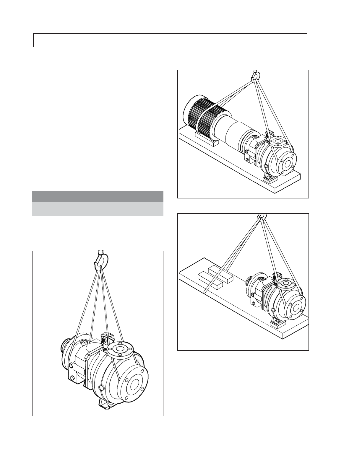
HANDLING
! WARNING
s
Failure to properly lift and support equipment
could result in serious injury or damage to pumps.
Use care when moving pumps. Lifting equipment must
be able to adequately support the entire assembly.
Hoist bare pumps, using a sling under the suction
flange and bearing housing.
the pump and driver.
Baseplate mounted units are moved with slings under
10 3296 M Group 6/05
Page 15
INSTALLATION
SITE/FOUNDATION..............................11
LEVEL BASEPLATE .............................12
ALIGNMENT AND ALIGNMENT PROCEDURE .............12
Alignment Checks..............................................12
Alignment Criteria .............................................13
SetUp.......................................................13
Measurement..................................................13
Angular Alignment .............................................13
Parallel Alignment .............................................14
Complete Alignment ............................................15
Alignment Troubleshooting ......................................15
GROUT BASEPLATE .............................15
PIPING......................................16
Suction Piping .................................................16
Discharge Piping ...............................................17
Final Piping Check .............................................17
3
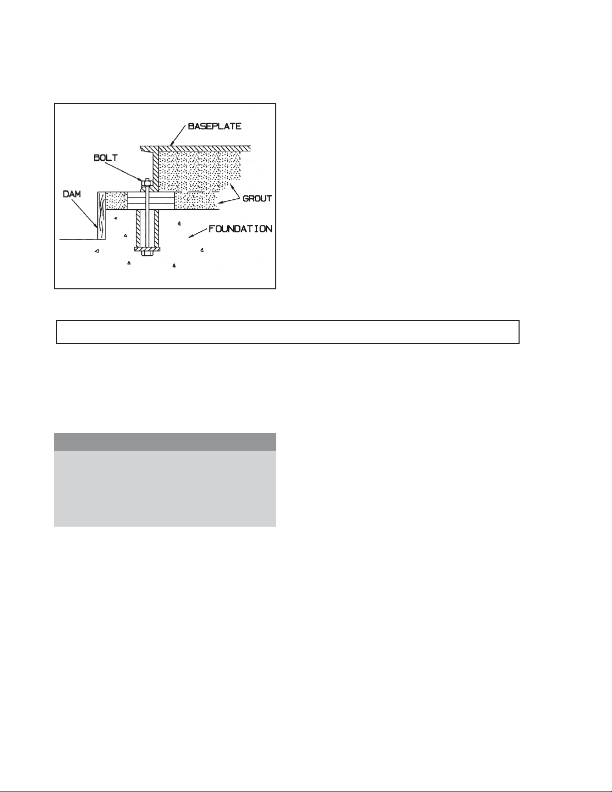
SITE/FOUNDATION
A pump should be located near the supply of liquid
and have adequate space for operation, maintenance,
and inspection.
Baseplate mounted pumps are normally grouted to a
concrete foundation, which has been poured on a solid
footing. The foundation must be able to
Fig. 4A
absorb any vibration and to form a permanent, rigid
support for the pumping unit.
The location and size of the foundation bolts are
shown on the outline assembly drawing, provided with
the pump data package.
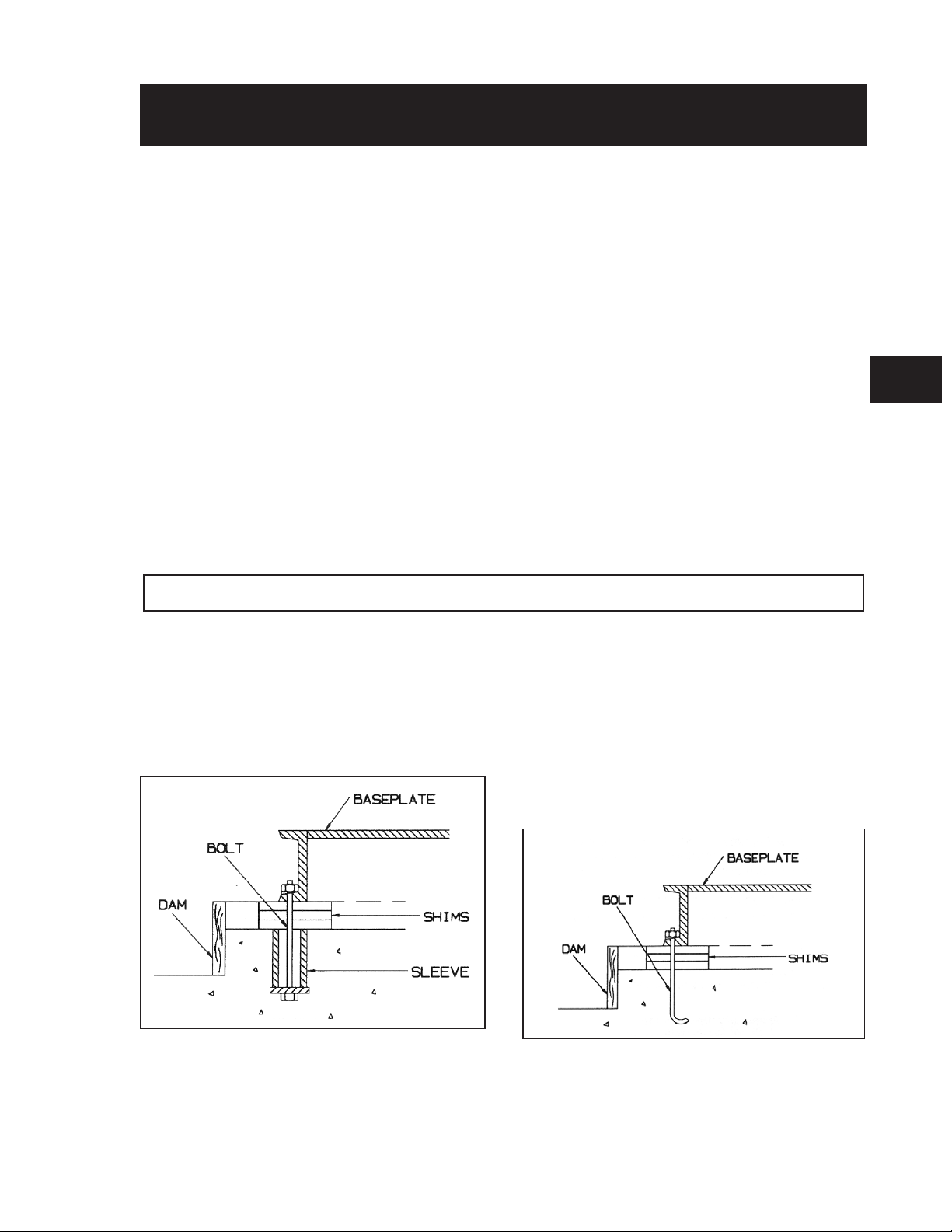
Foundation bolts commonly used are sleeve type (Fig.
4A) and J type (Fig. 4B). Both designs permit
movement for final bolt adjustment.
Fig. 4B
3296 M Group 6/05 11
Page 16
LEVEL BASEPLATE
1. Place 2 sets of wedges or shims on the foundation,
one set on each side of every foundation bolt. The
wedges should extend .75 in. (20 mm) to 1.5 in.
(40 mm) above the foundation, to allow for
adequate grouting. This will provide even support
for the baseplate once it is grouted.
2. Remove water and/or debris from anchor bolt
holes/sleeves prior to grouting. If the sleeve
Fig. 5A
type bolts are being used, fill the sleeves with rags to
prevent grout from entering.
3. Carefully lower baseplate onto foundation bolts.
4. Level baseplate to within .125 in.(3mm) over the length of
the base and .062 in. (1.5 mm) over the width of the base
by adjusting shims or wedges.
5. Hand tighten bolts.
Fig. 5B
ALIGNMENT AND ALIGNMENT PROCEDURE
! WARNING
s
Before beginning any alignment procedure make
sure driver power is locked out. Failure to lock out
driver power can result in serious personal injury.
The points at which alignment is checked and adjusted
are:
l
Initial Alignment is done prior to operation when
the pump and the driver are at ambient temperature.
l
Final Alignment is done after operation when the
pump and driver are at operating temperature.
Alignment is achieved by adding or removing shims
from under the feet of the driver and shifting
equipment horizontally as needed.
NOTE: Proper alignment is the responsibility of
the installer of the unit.
Accurate alignment of the equipment must be attained.
Trouble-free operation can be accomplished by following these
procedures:.
ALIGNMENT CHECKS
Initial Alignment (Cold Alignment)
l
Before Grouting Baseplate- To ensure alignment can be
obtained.
l
After Grouting Baseplate - To ensure no changes to
alignment have occurred during grouting process.
l
After Connecting Piping -To ensure that pipe strains haven’t
altered alignment. If changes have occurred, alter piping to
remove pipe strains on pump flanges.
Final Alignment (Hot Alignment)
l
After First Run -To obtain correct alignment when both
pump and driver are at operating temperature. Thereafter,
alignment should be checked periodically in accordance with
plant operating and maintenance procedures.
12 3296 M Group 6/05
Page 17
ALIGNMENT CRITERIA
Good alignment is achieved when dial indicator
readings as specified in the alignment procedure are
.002 in. (.05 mm) Total Indicated Reading (T.I.R.) or
less when the pump and driver are at operating
temperature (Final Alignment).
MEASUREMENT
1. To ensure accuracy of indicator readings, always
rotate both coupling halves together so indicators
contact the same point on coupling half Y. This
will eliminate any measurement problems due to
runout on coupling half Y.
During the installation phase, however, it is necessary
to set the parallel alignment in the vertical direction to
a different criteria due to differences in expansion rates
of the pump and driver. Table 1 below shows
recommended cold settings for electric motor driven
pumps based on different pumpage temperatures.
Driver manufacturers should be consulted for
recommended cold settings for other types of drivers
(steam turbines, engines, etc.)
Table 1
Cold Settings of Parallel Vertical Alignment
PUMPAGE
TEMPERATURE
50°F (10°C) .002in. (.05mm) LOW
150°F (65°C) .001in. (.03mm) HIGH
250°F (120°C) .005in. (.12mm) HIGH
350°F (175°C) .009in. (.23mm) HIGH
425°F (218°C) .013in. (.33mm) HIGH
SET DRIVER SHAFT
SET UP
1. Mount two dial indicators on one of the coupling
halves (X) so they contact the other coupling half
(Y) (Fig. 6).
2. Check setting of indicators by rotating coupling
half X to ensure indicators stay in contact with
coupling half Y but do not bottom out. Adjust
indicators accordingly.
2. Take indicator measurements with driver feet hold
down bolts tightened. Loosen hold down bolts
prior to making alignment corrections.
3. Take care not to damage indicators when moving
driver during alignment corrections.
ANGULAR ALIGNMENT
A unit is in angular alignment when indicator A
(Angular indicator) does not vary by more that .002 in.
(.05 mm) as measured at four locations 90° apart.
Vertical Correction (Top to Bottom)
1. Zero indicator A at top dead center (12 o’clock) of
coupling half Y.
2. Rotate indicators to bottom dead center (6
o’clock). Observe needle and record reading.
3. Negative Reading - The coupling halves are
further apart at the bottom than at the top. Correct
by either raising the driver feet at the shaft end
(add shims) or lowering the driver feet at the other
end (remove shims) (Fig. 7A).
Positive Reading - The coupling halves are closer
at the bottom than at the top. Correct by either
lowering the driver feet at the shaft end (remove
shims) or raising the driver feet at the other end
(add shims).
3
Fig. 7A
Fig. 6
4. Repeat steps 1-3 until indicator A reads .002 in
(.05 mm) or less.
3296 M Group 6/05 13
Page 18
Horizontal Correction (Side to Side)
1. Zero indicator A on left side of coupling half Y,
90° from top dead center (9 o’clock).
2. Rotate indicators through top dead center to the
right side, 180° from the start (3 o’clock). Observe
needle and record reading.
3. Negative Reading - The coupling halves are
further apart on the right side than the left. Correct
by either sliding the shaft end of the driver to the
left or the other end to the right.
Positive Reading - The coupling halves are closer
together on the right side than the left. Correct by
either sliding the shaft end of the driver to the
right or the other end to the left (Fig. 7B).
Positive Reading - Coupling half X is higher than
coupling half Y. Correct by adding shims of
thickness equal to half of the indicator reading
from each driver foot (Fig. 8A).
Fig. 8A
NOTE: Equal amounts of shims must be added to
or removed from each driver foot. Otherwise the
vertical angular alignment will be affected.
4. Repeat steps 1 through 3 until indicator P reads
within .002 in. (.05 mm) or less when hot, or per
Table 1 when cold.
Fig. 7B
4. Repeat steps 1 through 3 until indicator A reads
.002 in. (.05 mm) or less.
5. Re-check both horizontal and vertical readings to
ensure adjustment of one did not disturb the other.
Correct as necessary.
PARALLELALIGNMENT
A unit is in parallel alignment when indicator P
(parallel indicator) does not vary by more than .002 in.
(.05 mm) as measured at four points 90° apart at
operating temperature. Note the preliminary cold
setting criteria, Table 1.
Vertical Correction (Top to Bottom)
1. Zero indicator P at top dead center of coupling (12
o’clock) half Y (Fig. 6).
2. Rotate indicator to bottom dead center
(6 o’clock). Observe needle and record reading.
3. Negative Reading - Coupling half X is lower than
coupling half Y. Correct by removing shims of
thickness equal to half of the indicator reading
under each driver foot.
Horizontal Correction (Side to Side)
1. Zero indicator P on the left side of coupling half
Y, 90° from top dead center (9 o’clock).
2. Rotate indicators through top dead center to the
right side, 180° from the start. Observe needle and
record reading (3 o’clock).
3. Negative Reading - Coupling half Y is to the left
of coupling half X. Correct by sliding driver
evenly in the appropriate direction (Fig. 8B).
Positive Reading - Coupling half Y is to the
right of coupling half X. Correct by sliding driver
evenly in the appropriate direction.
Fig. 8B
NOTE: Failure to slide motor evenly will affect
horizontal angular correction.
14 3296 M Group 6/05
Page 19
4. Repeat steps 1 through 3 until indicator P reads
.002 in. (.05 mm) or less.
5. Re-check both horizontal and vertical readings to
ensure adjustment of one did not disturb the other.
Correct as necessary.
COMPLETE ALIGNMENT
A unit is in complete alignment when both indicators
A (angular) and P (parallel) do not vary by more than
.002 in. (.05 mm) as measured at four points 90° apart.
Vertical Correction (Top to Bottom)
1. Zero indicators A and P at top dead center
(12 o’clock) of coupling half Y.
2. Rotate indicator to bottom dead center
(6 o’clock). Observe the needles and record the
readings.
Alignment Troubleshooting
PROBLEM PROBABLE CAUSE REMEDY
Cannot obtain horizontal
(Side-to-Side) alignment, angular
or parallel
Cannot obtain vertical (Top to
Bottom) alignment, angular or
parallel
Driver feet bolt bound
Baseplate not leveled
properly, probably twisted.
Baseplate not leveled
properly, probably bowed.
3. Make corrections as outlined previously.
Horizontal Correction (Side to Side)
1. Zero indicators A and P on the left side of
coupling half Y, 90° from top dead center
(9 o’clock).
2. Rotate indicators through top dead center to
the right side, 180° from the start (3 o’clock).
Observe the needle, measure and record the
reading.
3. Make corrections as outlined previously.
4. Recheck both vertical and horizontal readings to
ensure adjustment of one did not disturb the other.
Correct as necessary.
NOTE: With experience, the installer will
understand the interaction between angular and
parallel and will make corrections appropriately.
Table 2
Loosen pump hold down bolts and slide pump and driver
until horizontal alignment is achieved.
Determine which corner(s) of the baseplate are high or low
and remove or add shims at the appropriate corner(s) and
realign.
Determine if center of baseplate should be raised or lowered
and correct by evenly adding or removing shims at the center
of the baseplate.
3
GROUT BASEPLATE
1. Clean areas of baseplate that will contact grout.
Do not use an oil-based cleaner because grout will
not bond to it.
2. Build a dam around foundation (Fig. 9A).
Thoroughly wet foundation.
3. Pour grout slowly through grout holes in
baseplate, until level with the top of the dam. The
use of non-shrink epoxy grout is recommended,
follow manufacturers recommendations. If
cementitious grout is used, remove air by puddling
or with a vibrator (Fig. 9A).
Fig. 9A
3296 M Group 6/05 15
Page 20
4. Allow grout to set.
6. Allow grout to set at least 48 hours.
5. Fill remainder of baseplate with grout. Remove air
as before (Fig. 9B).
Fig. 9B
PIPING
Guidelines for piping are given in the “Hydraulic
Institute Standards” (Edition 14, Centrifugal pump
section) and should be reviewed prior to pump
installation.
1. All piping must be supported independently and
must line up naturally with the pump flanges.
! WARNING
s
Never draw piping into place by forcing at the
flanged connections of the pump. This will impose
dangerous strains on the unit and cause
misalignment between pump and driver. Pipe
strain can adversely effect the operation of the
pump. That could result in serious personal injury
and damage to equipment.
2. Piping runs shall be designed to minimize friction
losses.
3. DO NOT make final connection of piping to pump
until grout has hardened and pump and driver
hold-down bolts have been tightened.
7. Tighten foundation bolts.
Alignment Check
Re-check alignment before continuing, using methods
previously described.
7. Gasket installation and materials must be suitable
for the service.
SUCTION PIPING
Properly installed suction piping is a necessity for
trouble free pump operation. Suction piping should be
flushed BEFORE connection to the pump.
1. Use of elbows close to the pump suction flange
should be avoided. There should be a minimum of
2 pipe diameters of straight pipe between the
elbow and suction inlet. Any elbows used should
be long radius.
2. Size suction pipe one or two sizes larger than
pump suction, with a reducer at suction flange.
Suction piping must never be of smaller diameter
than the pump suction.
3. Reducers, if used, must be eccentric at pump
suction flange with sloping side down.
4. Piping that handles hot liquids requires proper
installation of expansion loops/joints so that linear
expansion of piping will not cause mis-alignment.
5. Piping should be arranged to allow pump flushing
and draining prior to the removal of pump for
servicing.
6. System should be thoroughly cleaned prior to
installation.
4. Suction strainers, when used, must have a net
“free area” of at least three times the suction pipe
area.
5. Separate suction lines are recommended when
more than one pump is operating from the same
source of supply.
16 3296 M Group 6/05
Page 21

Suction Lift Conditions
1. Suction pipe must continuously slope upward
towards pump suction to eliminate air pockets.
2. All joints must be air tight.
FINAL PIPING CHECK
After Connecting Piping to the Pump
1. Rotate shaft several times by hand to be sure that
there is no binding and all parts are free.
3. A means of priming the pump must be provided,
such as a foot valve.
Suction Head/Flooded Suction Conditions
1. An isolation valve should be installed in suction
line to permit closing of the line for pump
inspection and maintenance.
2. Piping should be level or slope gradually
downward from source of supply.
3. No portion of piping should extend below pump
suction flange.
4. The suction pipe shall be submerged sufficiently
below the liquid surface to prevent vortices and air
entrainment at the supply.
DISCHARGE PIPING
1. Isolation and check valves should be installed in
discharge line. Locate check valve between
isolation valve and pump which will permit
inspection of check valve. An isolation valve is
required for isolating, priming, regulation of flow,
inspection and maintenance of the pump. A check
valve prevents pump damage due to reverse flow
when driver is turned off.
2. Check alignment, per the alignment procedure
outlined previously to determine absence of pipe
strain. If pipe strain exists, correct piping.
3
2. Increasers, if used, should be placed between
pump and check valves.
3. Cushioning devices should be used to protect
pump from surges and water hammer, if
quick-closing valves are installed in system.
3296 M Group 6/05 17
Page 22

18 3296 M Group 6/05
Page 23

OPERATION
PREPARATION FOR START-UP ......................19
Flushing Pump ................................................19
Checking Rotation .............................................19
Couple Pump and Driver ........................................20
Install Coupling Guard ..........................................20
Lubricating Bearings............................................20
Connect Condition Monitoring Devices .............................20
Priming Pump .................................................20
STARTING PUMP ...............................21
OPERATION ..................................21
General Considerations ..........................................21
Operating at Reduced Capacity ...................................21
Operating Under Freezing Conditions ..............................21
SHUTDOWN ..................................22
FINAL ALIGNMENT .............................22
4
PREPARATION FOR START-UP
FLUSHING PUMP
The 3296 is flushed with Ethylene Glycol Solution at
the factory to prevent accidental freezing during
shipping or storage at the customers site. Residual
amounts will remain in the pump but if this is a
problem, the 3296 can be flushed out following the
below procedure before pump is installed.
Procedure
3
1. Remove
flush liquid supply.
2. Devise a means of collecting flush liquid as it
drains out the suction nozzle or casing drain if
supplied.
3. Turn flush supply on and run for 5 minutes to
remove Ethylene Glycol residue.
4. When done, raise the coupling end of the pump
(suction flange down) to drain remaining flush
liquid from pump internals. Or, if pump is
equipped with a casing drain plug, remove it to
drain remaining liquid.
" NPT plug (408A) and connect clean
8
! WARNING
s
Failure to properly lift and support equipment
could result in serious injury or damage to pumps.
5. Replace any plugs removed and continue
preparation for start up.
CHECKING ROTATION
! CAUTION
l
Serious damage may result if pump is run in the
wrong rotation.
1. Lock out power to driver.
! WARNING
s
Lock out driver power to prevent accidental
start-up that could result in serious personal
injury.
2. Make sure coupling spacer is removed and
coupling hubs are fastened tightly to the shafts and
are not loose.
3296 M Group 6/05 19
Page 24
NOTE: Pump is shipped with coupling spacer
removed.
3. unlock driver power.
4. Make sure everyone is clear. Jog driver just long
enough to determine direction of rotation.
Rotation must correspond to arrow on bearing
frame.
Pure Oil Mist Lubrication - Pure oil mist is an
optional feature for the 3296. If your pump is equipped
with pure oil mist refer to oil mist generator
manufacturer’s instruction book for proper operation.
! WARNING
s
Operation of the unit without proper lubrication
will cause bearing failure, and pump seizure.
5. Lock out power to driver.
COUPLE PUMP AND DRIVER
! WARNING
s
Lock out driver power to prevent accidental
start-up that could result in serious personal
injury.
Lubricate coupling per manufacturer’s instructions and
install coupling spacer.
INSTALL COUPLING GUARD
Install coupling guard as defined in the appendix.
! WARNING
s
Never operate a pump without a coupling guard
properly installed. Operating pump without a
properly installed coupling guard can result in
serious personal injury.
LUBRICATING BEARINGS
Flood Oil Lubrication - Pumps are shipped without
oil. Fill bearing frame with oil, through filler
connection until oil level reaches center of sight-glass
(Fig A). A high quality turbine type oil, with rust and
oxidation inhibitors should be used as specified in
Table 5.
CONNECT CONDITION
MONITORING DEVICES
Always connect thermocouple to control panel and/or
temperature switch in driver starter. If unit is also
equipped with leak detection and vibration monitoring
systems, these must also be connected. (See Appendix
for wiring diagrams.)
PRIMING PUMP
Never start pump until properly primed (pump casing and
suction piping are full of liquid). Components such as
internal sleeve bearings depend on liquid for lubrication and
will quickly fail if run dry.
Your particular system conditions will dictate method
used to prime pump.
Fig. A
20 3296 M Group 6/05
Page 25

STARTING PUMP
1. Make sure suction valve and any recirculation or
cooling lines are open.
2. Fully close or partially open discharge valve as
dictated by system conditions.
3. Start driver.
! CAUTION
l
Immediately observe pressure gauges. If discharge
pressure is not quickly attained - stop driver,
reprime and attempt to restart.
4. Slowly open discharge valve until the desired flow
is obtained.
OPERATION
GENERAL CONSIDERATIONS
Always vary capacity with valve in discharge line.
NEVER throttle flow from suction side.
Driver may overload or magnets de-couple if pumpage
specific gravity (density) is greater than originally
assumed, or rated flow rate is exceeded.
Always operate the pump at or near the rated
conditions to prevent damage resulting from cavitation
or recirculation.
! CAUTION
l
Do not operate above rated temperature range of
magnets as this will weaken or ruin the magnets.
Table 3
Temperature Ratings
Magnetic Types
Neodymium Iron
NdFe
Samarium
Cobalt
SmCo
Drive
Designation
A,B,C,D,E,F 250°F (120°C)
AA,BB,CC,DD,
EE,FF
OPERATING AT REDUCED
CAPACITY
Rated
Temperature
425°F (220°C)
! CAUTION
l
Continuous operation against closed discharge
valve will cause pump to overheat. Overheating
the magnetic drive assembly will weaken or ruin
the magnets.
! WARNING
s
Continuous operation against closed discharge
valve may vaporize liquid creating an explosive
hazard due to confined vapor under high pressure
and temperature.
Table 4
Minimum Allowable Flow
Minimum Flow*
60 Hertz 50 Hertz
Pump
Group
M
* Based on water with a specific Gravity of 1.0 and
Specific Heat of 1.0
Size
2x3-8 60 32 11 6
3x4-8 - 112.5 40 23
3x4-8G 150 75 30 14
1x2-10 17 8.5 3 1.6
2x3-10 80 44 16 8
3x4-10H - 150 - 28
1
x3-13 - 41 - 8
1
2
2x3-13 - 80 - 15
GPM m
3600 1800 2900 1500
3
/h
OPERATING UNDER
FREEZING CONDITIONS
Exposure to freezing conditions, while pump is idle,
could cause liquid to freeze and damage the pump.
Liquid inside pump should be drained. Liquid inside
cooling coils, if supplied, should also be drained.
4
! WARNING
s
Do NOT operate pump below minimum rated flows or
with discharge valve closed. These conditions may
vaporize liquid creating an explosive hazard due to
confined vapor under high pressure and temperature.
3296 M Group 6/05 21
Page 26

SHUTDOWN
1. Slowly close discharge valve.
2. Shut down and lock out driver to prevent
accidental rotation.
FINAL ALIGNMENT
1. Run the unit under actual operating conditions for
a sufficient length of time to bring the pump and
driver up to operating temperature.
! WARNING
s
When handling hazardous and/or toxic fluids,
skin, eye and respiratory protection are required.
If pump is being drained, precautions must be
taken to prevent injury or environmental
contamination. Pumpage must be handled and
disposed of in conformance with applicable
environmental regulations.
2. Check and reset alignment per alignment
procedure outlined earlier.
3. Reinstall coupling guard per instruction in
appendix.
22 3296 M Group 6/05
Page 27

PREVENTIVE MAINTENANCE
GENERAL COMMENTS ...........................23
MAINTENANCE SCHEDULE ........................23
MAINTENANCE OF BEARINGS ......................24
TROUBLESHOOTING ............................25
GENERAL COMMENTS
A routine maintenance program can extend the life of your pump. Well maintained
equipment will last longer and require fewer repairs. You should keep maintenance
records, this will help pinpoint potential causes of problems. A sample form is in
the appendix that can be copied and used for this purpose.
MAINTENANCE SCHEDULE
5
Routine Maintenance
l
Bearing lubrication
l
Temperature monitoring
l
Vibration analysis
l
Discharge pressure
Routine Inspections
l
Check level and condition of oil through sight glass
on bearing frame.
l
Check for unusual noise, vibration, and bearing
temperatures.
l
Inspect pump and piping for leaks.
3 Month Maintenance
l
Check foundation hold down bolts of motor and
pump for tightness.
l
Change oil per section V-C.
l
Check alignment per section III-B.
Yearly Inspections
l
Check pump capacity, pressure, and power. If the
pump performance does not satisfy your process
requirements, the pump should be disassembled and
inspected. Worn parts should be replaced.
3296 M Group 6/05 23
Page 28

MAINTENANCE OF BEARINGS
OIL LUBRICATED BEARINGS
Oil level is measured through sight glass. Oil level
must not fall below center of site glass. An increase in
level may be noted after start up due to oil circulation
within the bearing frame. Change Oil after 200 hours
for new bearings, thereafter every 4000 operating
Bearing Frame Lubrication Requirement
Pumpage Temp. of
Oil Grades
ISO Grade VG 68 Synthetic VG 68
Approximate SSU
100°F (38°C)
DIN 51517 C 68 Synthetic C68
Kenematic Viscosity at 40°C
(105°F)
2
(mm
/sec)
Acceptable
less than 325°F (160°C)
Exxon Teresstic EP 68
Chevron GTS Oil 68
Mobil DTE 26
Gulf Harmony 68
Shell Tellus Oil 68
Phillips Mangus Oil 315
Phillips MM SAE 20-20W
Phillips HDS SAE 20-20W
hours or 6 months, which ever period is shorter.
Change oil every 2000 operating hours under severe
operating conditions, such as high temperature services
[pumpage temperatures in excess of 325°F (160°C)].
We recommend using Table 5 to help determine your
lubricating oil needs.
Table 5
Pumpage Temp. of
325° - 375°F
(160° - 190C°)
with bearing frame cooling
300 Synthetic 300
68 Synthetic 68
Pumpage Temp. of
greater than 375°F
(190°C)
with bearing frame cooling
Royal Purple Synfilm 68
NOTE: This is a list of oils that meet the lubrication requirements of this pump. It is not intended to be an
endorsement of products listed nor exclude other oils that meet these requirements.
24 3296 M Group 6/05
Page 29

Table 6
Troubleshooting Pump
PROBLEM /
MALFUNCTION PROBABLE CAUSE REMEDY
No liquid delivered
Pump not
producing rated
flow or head
Pump starts then
stops pumping
Pump not primed.
Suction line clogged.
Impeller clogged with foreign material. Disassemble and remove blockage.
Magnet de-coupling
Air leak in suction line Check for leakage and correct.
Impeller partly clogged Back flush pump to clean impeller
Worn impeller rings Replace defective part as required
Insufficient suction head
Worn or broken impeller Inspect and replace if necessary
Improperly primed pump Reprime pump
Air leak in suction line Check for leakage and correct
Magnet de-coupling
Air or vapor pockets in suction line
Reprime pump, check that pump and
suction line are full of liquid.
Check suction line pressure. If low,
locate and remove obstructions.
Shut down. Check temperature and
viscosity of pumpage. Check magnets
with breakaway torque test.
Ensure that suction line shutoff valve is
fully open and line is unobstructed.
Check suction pressure
Shut down. Check temperature and
viscosity of pumpage. Check magnets
with breakaway torque test.
Rearrange piping as necessary, to
eliminate air pockets
Bearings run hot
Pump is noisy or
vibrates
Improper lubrication Check lubricant for suitability and level
Lube cooling Check cooling system
Improper alignment Check pump alignment
Improper pump/driver alignment Align shafts
Partly clogged impeller causing
imbalance
Broken or bent impeller or shaft Replace as required
Base not rigid enough
Worn bearings Replace
Suction or discharge piping not
anchored or properly supported
Pump is cavitating Increase NPSH available.
Disassemble and remove blockage
Tighten hold down bolts of pump and
motor or adjust stilts. Check grout.
Anchor per Hydraulic Institute Standards
recommendations (Edition 14, Centrifugal pump
section).
3296 M Group 6/05 25
Page 30

Table 6
Troubleshooting Pump
PROBLEM /
MALFUNCTION PROBABLE CAUSE REMEDY
Motor requires
excessive power
Condition
monitoring device
shuts down pump
Head lower than rating. Pumps too much
liquid
Liquid heavier than expected. Check specific gravity and viscosity.
Head higher than rating, capacity at
rating
Rotating parts binding or severly worn
Damaged sleeve & thrust bearings Replace as required.
Plugged recirculation circuit
Recirculation liquid vaporization
Damaged containment shell Replace as required.
Magnets decoupled
Pump run dry
Excessive motor power
Install throttle valve.
Check impeller diameter.
Check internal wearing parts for proper
clearances.
Disassemble and remove blockage. Determine and
correct cause of blockage.
Check actual liquid temperature versus design
temperature. Check actual NPSH available versus
design. Check minimum flow requirement for pump
size. Check recirculation circuit and flush screen for
blockage. Correct all as necessary.
Check temperature and viscosity of pumpage. Check
magnets with breakaway torque test.
Check control device for proper operation. Check
suction line for blockage. Reprime pump.
System head lower than rating. Pumps too much liquid.
Check rotating parts for binding and wear. Liquid
heavier than expected.
26 3296 M Group 6/05
Page 31

DISASSEMBLY & REASSEMBLY
REQUIRED TOOLS ..............................27
PREPARATION FOR DISASSEMBLY ...................29
DISASSEMBLY.................................29
INSPECTIONS .................................36
Casing .......................................................36
Wear Ring Clearances...........................................36
Impeller......................................................37
Flush Screen ..................................................37
Frame Adapter ................................................37
Silicon Carbide Bearings ........................................38
Containment Shell..............................................38
Magnets......................................................38
Bearing Frame.................................................38
REASSEMBLY .................................39
SECTIONALS, PARTS LIST, MATERIALS OF CONSTRUCTION ....50
REQUIRED TOOLS
! WARNING
s
This pump contains extremely strong magnets. The
use of non-magnetic tools and work surface are
required.
Non-Magnetic Tools
l
1-5/16" Socket wrench with 6" minimum extension
l
9/16" Socket wrench with speed handle
Tools
NOTE: Keep magnetic tools away from magnets.
l
3296 Tool Kit
l
Assorted Open end wrenches
l
3/4", 15/16" sockets
l
Socket wrench with minimum 4" minimum
extension
l
Needle nose pliers
l
Torque wrench
l
Screw drivers
l
1/2", 5/8" stud drivers
l
Lip seal driver
l
Non-metallic hammer
l
Hammer
l
Heat gun
l
Non-Magnetic Support blocks
3296 M Group 6/05 27
Page 32

Table 7
3296 M Tool Kit #R296TK01
Tool Use Qty Tool Number Mat’l
A
B O-ring Installation Tool 1 A03817A Nylon
C Shaft Wrench 1 A01676A 304SS
D
E Sleeve Bearing Driver 1 A03817A Nylon
Bearing Frame Jacking Screw
Drive Carrier Jacking Screws
Wear Ring Jacking Screw
Wear Ring Alignment Screw
End Cover Jacking Screw
4 A03777A02 304SS
3 49521 61 304SS
28 3296 M Group 6/05
Page 33

PREPARATION FOR DISASSEMBLY
! WARNING
s
The 3296 usually handles hazardous and/or toxic
fluids. Skin, eye and respiratory protection
required. Precautions must be taken to prevent
injury or environmental contamination.
! WARNING
s
If pump has failed, pumpage may be present in the
area between the adapter and the frame and also
inside of the bearing frame.
1. Lock out power to driver.
2. Shut off all valves controlling flow to and from pump.
3. Drain and decontaminate pump in accordance with
all Federal, State, local and company regulations.
The 3296 should be drained and thoroughly flushed
before it is removed from the piping. After isolating
the pump from the system flush the pump using a
compatible liquid.
DISASSEMBLY
! WARNING
s
Ensure pump is isolated from system and pressure
is relieved before any plugs are removed or piping
disconnected.
4. To decontaminate pump recirculation path,
remove plug 408A and inject flush into external
flush connection.
5. Disconnect all piping and auxiliary equipment.
6. Remove coupling guard.
7. Remove coupling.
NOTE: If the only service required is to change
the impeller, the flush screen or the wear ring,
please refer to the appendix “Changing the
Impeller”.
8. Remove casing foot and bearing frame foot bolts.
9. Remove bare pump from baseplate and take to shop.
! WARNING
s
Each component must be individually
decontaminated using procedures in accordance
with all federal, state, local and company
environmental regulations.
! WARNING
s
The magnets contained in this unit are extremely
powerful. Keep magnetic drive components and
magnetic tools apart from each other by a
minimum of six (6) feet [two (2) meters]. Serious
injury to fingers and hands will result.
NOTE: When working on pump use a bench with
a non-magnetic work surface such as wood with a
brass surface.
! CAUTION
l
The shop area must be clean and free of any
substances that would contaminate the magnets,
ex. ferrous metals.
1. Remove thermocouple (758B) (Fig. A).
2. Remove casing nuts (425). Remove casing (100)
(Fig. A).
3. Remove casing gasket (351) and discard
(Fig. A).
4. Place shaft wrench on coupling end as shown.
Remove impeller bolt (198), impeller lockwasher
(199A) and impeller washer (199) (Fig. B).
3296 M Group 6/05 29
Page 34

5. Place unit in vertical position resting on
non-magnetic blocks (Fig. C).
! WARNING
s
Pump and some individual components weigh
more than 50 lbs (23 kg). Care should be taken
when handling.
6. Remove frame adapter bolts (370) (Fig. C).
! WARNING
s
Do NOT attempt to remove bearing frame (228)
without using the jacking screws. Personal injury
and damage to the magnets will occur.
8. Evenly tighten bearing frame jacking screws until
bearing frame (228) is above containment shell
(750) as shown. Lift bearing frame (228) off
frame adapter (108) and set aside away from
attracting metals.
Use of a lifting device with a strap through two
opposite eyes in the jacking screws is
recommended.
Remove adapter to frame gasket (360W) and
discard (Fig. E).
! WARNING
s
The magnets contained in this unit are extremely
powerful. Keep magnetic drive components and
magnetic tools apart from each other by a
minimum of six (6) feet [two (2) meters]. Serious
7. Remove bearing frame using four (4) jacking
screws (Fig. D).
injury to fingers and hands will result.
! WARNING
s
This component can weigh more than
50 lbs (23 kg). Care should be taken when
handling.
30 3296 M Group 6/05
Page 35

9. Remove clamp ring screws (370B) and lock
washers (136A) (Fig. F).
NOTE: Place a folded clean cloth or cardboard
under frame adapter assembly to soften impact of
driven magnet assembly (740A) on work surface.
Shaft and magnet assembly should rest on work
surface.
13. Remove impeller (101) (Fig. H).
NOTE: It may be necessary to use a puller. Puller
must be placed under vanes so as not to damage
the impeller.
! WARNING
s
Use non-magnetic socket and speed wrench to
avoid personal injury or damage to parts.
10. Remove clamp ring (141C) and containment shell
(750) simultaneously (Fig. F).
11. Remove O-ring (412M) and discard (Fig. F).
12. Orient frame adapter assembly in vertical position
and support on blocks (Fig. G).
14. Press driven shaft (122A) out until it disengages
(Fig. I).
NOTE: Light tapping with a non-metallic
hammer may be necessary to disengage shaft.
3296 M Group 6/05 31
Page 36

! WARNING
s
The magnets contained in this unit are extremely
powerful. Keep magnetic drive components and
magnetic tools apart from each other by a
minimum of six (6) feet [two (2) meters]. Serious
injury to fingers and hands will result.
15. Lift frame adapter (108) off shaft (122). Set aside.
18. Press driven shaft (122A) out of driven magnet
assembly (740A). Remove key (178X) (Fig. K).
19. Wrap driven magnet assembly (740A) in a clean
cloth to keep clean and set aside away from
attracting metals.
! WARNING
s
The magnets contained in this unit are extremely
powerful. Keep magnetic drive components and
magnetic tools apart from each other by a
minimum of six (6) feet [two (2) meters]. Serious
injury to fingers and hands will result.
NOTE: Outboard rotary sleeve bearing will
remain on shaft.
! WARNING
s
This component can weigh more than 50 lbs (23
kg). Care should be taken when handling.
16. Remove thrust bearing holder key from shaft
(178S) (Fig. J).
17. Remove outboard rotary sleeve bearing (117C)
and two spacer gaskets (360). Discard spacer
gaskets (Fig. J).
178S
20. Remove and discard four shaft O-rings (497P)
(Fig. L). Set shaft aside.
21. Place frame adapter (108) on work bench as
shown. Remove wear ring bolts (353B) and flush
screen (187) (Fig. M).
32 3296 M Group 6/05
Page 37

22. Place wear ring jacking screws in threaded jacking
screw holes in wear ring (144) as shown. Tighten
bolts evenly and in sequence until wear ring (144)
can be removed (Fig. N).
NOTE: Do not over tighten jacking bolts. Tighten
until snug and move to next one in sequence.
23. Remove wear ring (144) and stationary bearing
key (178K) (Fig. N).
25. Set frame adapter (108) on blocks, impeller side
down, and place clean cloth underneath as shown
to absorb impact when bearings drop (Fig. P).
! CAUTION
l
The bearing material is extremely brittle. Take
every precaution necessary to avoid shock to the
bearings.
26. Press out thrust bearing assembly (212) and
inboard stationary sleeve bearing (117B) using
hand pressure and sleeve bearing driver oriented
as shown (Fig. P).
Jacking Screws
24. Remove inboard rotary sleeve bearing (117D) and
two spacer gaskets (360) (Fig. O). Discard
gaskets.
27. Set aside thrust bearing assemblies (212) and
outboard stationary sleeve bearing (117B).
28. Press outboard stationary sleeve bearing (117A)
out of frame adapter (108) using sleeve bearing
driver oriented as shown (Fig. Q).
Sleeve Bearing
Driver
29. Invert frame adapter (108), impeller end up, and set on
bench. Remove outboard stationary O-rings (496A)
and inboard stationary O-rings (496B). Discard
O-rings (Fig. R).
3296 M Group 6/05 33
Page 38

30. Bolt or clamp bearing frame (228A) to bench
(Fig. S).
31. Place shaft wrench on drive shaft (122B) and
loosen the drive magnet assembly hex nut (355A)
until it can be removed by hand. Leave nut on
shaft for now (Fig. T).
! WARNING
s
Use non-magnetic socket and extension to avoid
personnel injury or damage to parts.
Fig. R
Fig. T
32. Remove two rub ring retaining screws (372Y)
(Fig. U).
33. Thread two rub ring jacking screws into holes
provided in rub ring (144A) until they bottom
(Fig. U).
34. Tighten jacking screws until rub ring can be
removed.
Fig. S
Fig. U
35. Carefully invert bearing frame assembly, drive
magnet assembly up. Clamp firmly to work bench
(Fig. V).
! WARNING
s
This component can weigh more than 50 lbs (23
kg). Care should be taken when handling.
34 3296 M Group 6/05
Page 39

NOTE: A workbench with a two inch hole in the
surface to accommodate the coupling end of shaft
works well (Fig. V).
Fig. V
Fig. W
36. Remove drive magnet assembly nut (355A) from
shaft (Fig. W).
37. Thread the drive carrier jacking screws into holes
provided in drive magnet assembly (740B) until
screws bottom against frame (Fig. W).
38. Tighten jacking screws evenly and in sequence
until drive magnet assembly is free from shaft.
Using a lifting strap through the eyebolts and a
lifting device, raise drive magnet assembly.
Remove from frame and set aside away from
attracting metals (Fig. W).
! WARNING
s
This component can weigh more than 50 lbs (23
kg). Care should be taken when handling.
! WARNING
s
The magnets contained in this unit are extremely
powerful. Keep magnetic drive components and
magnetic tools apart from each other by a
minimum of six (6) feet [two (2) meters]. Serious
injury to fingers and hands will result.
40. Remove bearing end cover bolts (370C) (Fig. X).
41. Install jacking screws in jacking screw holes,
tighten evenly to back off bearing end cover
(109A) (Fig. X).
42. Slide bearing end cover (109M) back. Labyrinth
oil seal (332A) will slide back with end cover
(Fig. X).
43. Remove labyrinth seal (332A) (Fig. X).
44. Remove bearing end cover (109A). Remove
gasket (360A) and discard (Fig. X).
39. Remove drive magnet assembly key (178Y)
(Fig. W).
Fig. X
3296 M Group 6/05 35
Page 40

45. Remove bearing wavewasher (529) from bearing
bore (Fig. Y).
46. Remove drive shaft (122B) with ball bearings
(112) from bearing housing (228) (Fig. Y).
Fig. Y
INSPECTIONS
47. Press bearings (112) off shaft and discard.
48. Remove lip seal (333D) as shown and discard
(Fig. Z).
Fig. Z
Model 3296 parts must be inspected to the following
criteria before reassembly to ensure pump will run
properly. Any part not meeting required criteria should
be replaced.
NOTE: Various tolerances specified on the 3296
are held extremely close, measure parts at standard
temperature 68°F(20°C) to ensure accurate
measurement.
CASING (100)
Casing (100) should be inspected for excessive wear or
pitting. It should be repaired or replaced if it exceeds
the following criteria.
Table 8
Minimum Casing
Thickness
Minimum
Thickness Inches
Group Pump Size
2x3-8
3x4-8
3x4-8G
M
1x2-10
2x3-10
3x4-10H
1
1
x3-13
2
2x3-13
(mm)
0.31 (7.9)
0.31 (7.9)
0.31 (7.9)
0.37 (9.4)
0.37 (9.4)
0.37 (9.4)
0.37 (9.4)
0.37 (9.4)
WEAR RING CLEARANCES
Refer to Table 9 to check wear ring clearances.
36 3296 M Group 6/05
Page 41

Group Size
2x3-8
3x4-8
3x4-8G
1x2-10
M
2x3-10
3x4-10H
1
1
x3-13
2
2x3-13
Table 9
Diametrical Wear Ring Clearance
LOCATION
Ê
Impeller to casing
in. (mm)
New Replace New Replace New Replace New Replace
.024 - .028
(.61 - .71)
.026- .030
(.66 - .76)
.026 - .030
(.66 - .76)
.022 - .026
(.56 - .66)
.026 - .030
(.66 - .76)
.027 - .031
(.69 - .79)
.026 - .030
(.66 - .76)
.026 - .030
(.66 - .76)
.048 (1.22)
.052 (1.32)
.052 (1.32)
.044 (1.12)
.052 (1.32)
.054 (1.37)
.052 (1.32)
.052 (1.32)
Impeller to wear ring
.024 - .028
(.61 - .71)
.026 - .030
(.66 - .76)
.026 - .030
(.66 - .76)
.026 - .030
(.66 - .76)
.026 - .030
(.66 - .76)
.026 - .030
(.66 - .76)
.026 - .030
(.66 - .76)
.026 - .030
(.66 - .76)
Ë
in. (mm)
.048
(1.22)
.052
(1.32)
.052
(1.32)
.052
(1.32)
.052
(1.32)
.052
(1.32)
.052
(1.32)
.052
(1.32)
Driven magnet
to adapter
in (mm)
.024 - .028
(.61 - .71)
Ì
.048 (1.22)
Drive Magnet
to Rub Ring
in (mm)
.067 - .073
(1.70 -
1.85)
Í
.090 (2.29)
IMPELLER (101)
1. Inspect wear ring surface for signs of pitting.
2. Inspect front and back wear ring clearance per
wear ring clearance Table 9.
3. Inspect leading and trailing edges of vanes for
pitting, and erosion or corrosion damage.
4. Check impeller bore and keyway. Bore should
measure .7490 to .7505 in. (19.025 to 19.063 mm).
If oversize, replace impeller.
5. Check impeller balance per Table 10. Values are
based on ISO - 1940/1 grade 2.5 at 3000 RPM.
Table 10
Impeller Balance Specification
Part # Pattern # Part Name oz-inches
C03333A 68455 2x3-8 Impeller .04
C03363A 68491 3x4-8 Impeller .06
C03362A 68490 3x4-8G Impeller .05
C03335A 68456 1x2-10 Impeller .06
C03172A 68325 2x3-10 Impeller .06
C03367A 68457 3X4-10H Impeller .07
C03360A 68358 1.5x3-13 Impeller .09
C03265A 68383 2x3-13 Impeller .09
FLUSH SCREEN (187)
1. Must be clean and free from holes or tears.
2. Inspect for erosion and corrosion.
FRAME ADAPTER (108)
1. Inspect wear ring clearances per clearance Table
9.
2. Check all internal recirculation passages to make
sure they are open and free from excessive wear
due to erosion or corrosion.
3296 M Group 6/05 37
Page 42

SILICON CARBIDE BEARINGS
(117A-D)
Sleeve Bearings
1. Inspect bearings for cracks and chips.
2. Inspect dimensions per Table 11.
Table 11
Bearing Clearances
Group Location
Shaft to Bearing
M
Thrust Bearings (237)
1. Inspect for cracks or chips.
Bearing to
Bearing
Bearing to
Adapter
New Clearance
in. (mm)
.0045 - .0065
(.114 - .165)
.003 - .006
(.076 - .152)
.0015 - .0035
(.038 - .089)
Replace
in. (mm)
.0085
(.216)
.008
(.203)
.0055
(.140)
CONTAINMENT SHELL (750)
1. Wall thickness .050 in. (1.3 mm) minimum.
2. Must be free from pitting or cracks.
3. Grooves in excess of .005 in. (.13 mm) require
containment shell replacement.
MAGNETS (740A & B)
Driven Magnet Assembly (740A)
! WARNING
s
The magnets contained in this unit are extremely
powerful. Keep magnetic drive components and
magnetic tools apart from each other by a
minimum of six (6) feet [two (2) meters]. Serious
injury to fingers and hands will result otherwise.
Drive Magnet Assembly (740B)
! WARNING
s
The magnets contained in this unit are extremely
powerful. Keep magnetic drive components and
magnetic tools apart from each other by a
minimum of six (6) feet [two (2) meters]. Serious
injury to fingers and hands will result otherwise.
NOTE: The magnets are extremely brittle. It is
normal to have chips (up to 10% of the magnet
at
surface) per MMPA standard no. 0100-90.
1. Magnets must be free of major cracks (extending
over 50% of surface) and also free of
imperfections that create loose particles.
2. If magnets and drive magnet carrier were exposed
to product, they should be replaced.
3. Inspect drive magnet carrier for cracks and replace
if any are found.
4. Drive magnet carrier hub O.D. must be free from
grooves and scratches greater than .005 in. (.13
mm).
5. Inspect magnets for proper bonding to metal
carrier.
BEARING FRAME (228)
1. Visually inspect frame and frame foot for cracks.
2. Inspect for corrosion or pitting if frame has been
exposed to pumpage
3. Inspect frame bearing bores. The maximum
acceptable bore is 3.1506 in. (80.025 mm).
4. Inspect ball bearings for contamination and
damage.
1. Must be free from bulges.
2. Must be free of pits and scratches exceeding .005
in. (.13 mm) deep.
3. Must be free of erosion or corrosion exceeding
.005 in. (.13 mm) deep.
4. Inspect wear ring clearance per wear ring
clearance Table 9.
5. Check pump-out vanes for cracks or corrosion.
6. Ensure circulation holes are open.
5. Make sure gasket surfaces are clean.
6. Visually inspect bearing end cover (109A) for
cracks and pits. Gasket surface must be clean.
7. Inspect labyrinth seal O-rings (332A) for cuts and
cracks.
8. Replace lip seal.
38 3296 M Group 6/05
Page 43

REASSEMBLY
Please refer to the Appendix for assembly and
inspection checklist for your convenience. Make a
copy and checkoff parts as they are assembled.
Refer to Table 12 for torque values while reassembling
pump.
Table 12
*Bolt Torque Table
Ft-Lbs (Nm)
Location
Drive Magnet Assy Nut (355A)
Wear Ring Screw (353B)
Clamp Ring Screws (370B)
Impeller Nut (198)
Adapter to Frame Srews (370)
Casing Nuts (425)
* Torque values based on Dry Threads
! WARNING
s
The magnets contained in this unit are extremely
powerful. Keep magnetic drive components and
magnetic tools apart from each other by a
minimum of six (6) feet [two (2) meters]. Serious
injury to fingers and hands will result.
Dry
Threads
120 (160)
17 (25)
12 (16)
45 (60)
50 (70)
45 (60)
3. Place the first spacer gasket (360) over driven
shaft (122A) (Fig. B) and shoulder against driven
magnet assembly.
NOTE: Use new spacer gaskets when
reassembling.
NOTE: Spacer gaskets require care when
handling to avoid damage.
4. Place O-ring installation tool on driven shaft
(122A) and install impeller washer (199) and bolt
(198), hand tighten. Install two outboard shaft
O-rings (497P) (Fig. B).
NOTE: Cover first three O-ring (497P) grooves
with tape before installing O-rings. Remove tape
as necessary to install O-rings (497P). O-rings
may have to be heat shrunk to be fully seated in
O-ring grooves. Do not overheat O-rings
Fig. B
1. Install key (178X) on driven shaft (112A) (Fig.
A).
NOTE: Ensure shaft O-ring, grooves, shaft
keyways and keyway in driven carrier are free of
burrs.
2. Install driven shaft (122A) into driven magnet
assembly (740A) (Fig. A).
5. Put lube on O-rings.
6. Install outboard rotary sleeve bearing (117C) on
driven shaft (122A) using bearing driver (Fig. C).
7. Place the second spacer gasket (360) over driven
shaft (122A). Shoulder against outboard rotary
sleeve bearing (117C) (Fig. C).
3296 M Group 6/05 39
Page 44

Fig. C
8. Set partially built driven assembly aside well away
from attracting metals. Prepare to build up frame
adapter assembly.
! WARNING
s
The magnets contained in this unit are extremely
powerful. Keep magnetic drive components and
magnetic tools apart from each other by a
minimum of six (6) feet [two (2) meters]. Serious
injury to fingers and hands will result otherwise.
! CAUTION
l
Carefully stretch O-rings so when installed they fit
securely in O-ring groove. Care must be taken not
to over stretch the O-rings.
9. Install outboard anti-rotation pin (445B) in frame
adapter (108) (Fig. D).
Fig. D
10. Install outboard stationary O-rings (496A)
(Fig. E). Lubricate O-rings and bores.
Fig. E
11. Install inboard stationary O-rings (496B)
(Fig. F). Lubricate O-rings.
40 3296 M Group 6/05
Page 45

Fig. F
12. Install outboard stationary sleeve bearing (117A)
(Fig. G). The anti-rotation slot in bearing (117A)
must line up with anti-rotation pin (445B) in
outboard end of frame adapter (108). Press
outboard stationary sleeve bearing (117A) in by
hand using sleeve bearing driver.
14. With partially assembled rotating assembly
positioned as shown install into partially built
frame adapter assembly (Fig. H).
Fig. H
15. Carefully roll adapter with rotary assembly onto
face of rotary assembly (impeller end of shaft
facing up).
! WARNING
s
Ensure rotary assembly does not fall out of
adapter. This could cause bodily injury and
damaged parts.
16. Install a tolerance ring (505) into both thrust
bearing holders (212) (Fig. I). Shoulder tolerance
ring against face in thrust bearing holder.
NOTE: It may be necessary to form ring with your
fingers to insure good contact between ring OD
and holder bore.
Fig. G
13. Install thrust bearing holder key (178S) into driven
shaft (122A) (Fig. H). Use a small amount of
O-ring lube in keyway to hold key in place.
3296 M Group 6/05 41
Fig. I
Page 46

17. Install thrust collar bearing (237) (chamfered side
in) into bore of thrust bearing with the tolerance
ring (Fig. J). Ensure bearing is fully seated in
holder.
Fig. J
NOTE: To ease assembly and minimize the risk of
damage to the thrust bearing (237), the use of an
arbor press is recommended during installation
(Fig. K). Use a small amount of O-ring lube on
the tolerance ring and O.D. of thrust collar before
assembly.
19. Install thrust bearing holder gasket (428C) into
groove on back of thrust bearing assembly on
shaft (Fig. L). Use a small amount of O-ring lube
in groove to hold gasket in place.
20. Install the other thrust bearing holder onto the
shaft with the bearing facing up (towards the
impeller end) (Fig. L). Again, carefully align the
keyway with the key.
21. Place the third spacer gasket (360) over driven
shaft and shoulder against inboard thrust bearing
assembly (Fig. L).
NOTE: Ensure thrust holder key and keyways are
free of burrs.
NOTE: Take a pencil and make a reference mark
locating the thrust bearing key (178S) in relation
to the frame adaptor. This will help align the
keyway of the thrust bearing assemblies (212) with
the thrust bearing key (178S).
Fig. L
22. Place O-ring installation tool on driven shaft
(122A) and install impeller washer (199) and bolt
Fig. K
18. Install one of the thrust bearing assemblies onto
the shaft with the bearing facing down (towards
the driven magnet assembly)
(198) as before (Fig. B). Install two shaft O-rings
(497P) and then remove tool.
NOTE: Tape first groove on shaft to allow O-ring
to slide over. O-ring may have to be heated to seat
in groove. Do not overheat O-rings.
(Fig. L). Be careful to align the keyway on the
thrust bearing assembly with the thrust bearing
key (178S) on the shaft.
42 3296 M Group 6/05
Page 47

23. Press inboard stationary sleeve bearing (117B)
into frame adapter (108) by hand using bearing
driver. The stationary inboard key slot in the
inboard stationary bearing (117B) must line up
with the woodruff key slot in the frame adapter
(108) as shown. Press inboard stationary bearing
in by hand using bearing driver (Fig. M).
Fig. M
24. Press inboard rotary sleeve bearing (117D) onto
driven shaft (122A) using bearing driver (Fig. N).
178K
Fig. O
27. Install wear ring (144) (Fig. P). Place wear ring
alignment screws through unthreaded holes in
wear ring (144) and thread into wear ring bolt
holes in frame adapter (108). These are used to
align the wear ring holes in the frame adapter
(108). Press wear ring (144) into the frame adapter
(108). Remove alignment screws after wear ring is
in place.
Fig. N
25. Install stationary inboard bearing key (178K) in
Fig. P
frame adapter (108) (Fig. O).
26. Install the fourth spacer gasket (360) (Fig. O) and
shoulder against face of inboard rotary sleeve
bearing (117D).
3296 M Group 6/05 43
28. Install flush screen (187) (Fig. Q).
29. Install wear ring clamp screws (353B) (Fig. Q).
Page 48

30. Bend long narrow tang of impeller lockwasher
(199A) so tang will fit in slot on impeller washer
(199) (Fig. R).
Fig. R
NOTE: Support bottom end of shaft to prevent
shaft from moving during installation of thrust
bearing assemblies and impeller.
NOTE: Ensure impeller key and keyway are free
of burrs.
31. Install impeller key (178) and impeller (101) (Fig.
S). Install impeller washer (199) and impeller bolt
(198). Hand tighten impeller bolt (198) only.
NOTE: Unit can now be moved safely. Rotary
assembly will not fall out of adapter once impeller
is installed.
Fig. S
32. Place unit on non-magnetic blocks, as shown, with
impeller facing down (Fig. T).
33. Install containment shell to adapter O-ring (412M)
(Fig. U).
34. Install containment shell (750) and containment
shell clamp ring (141C) (Fig. U).
35. Install containment shell clamp ring screws
(370B) and lock washers (136A) (Fig. U). Torque
per bolt Torque Table 12 in beginning of this
section.
44 3296 M Group 6/05
Page 49

! WARNING
s
Use non-magnetic socket and speed wrench to
avoid personal injury or damage to parts.
Fig. W.
38. Bolt or clamp bearing frame (228) to work bench
(Fig. X).
36. Install ball bearings (112) on drive shaft (122B)
(Fig. V).
NOTE: There are several methods used to install
bearings. The preferred method is to use an
induction heater that heats as well as demagnetizes the bearings.
37. Install inboard lip seal (333D) (Fig. W).
Fig. X
39. Install drive shaft (122B) with ball bearings (112)
in bearing frame (228) as shown. The threaded
end of the shaft goes toward the magnets (Fig. Y).
NOTE: It may be necessary to lightly press shaft
with bearings into the bearing frame (228). It is
important to press the bearings in by putting a
sleeve on the inner race of the outboard ball
bearing.
3296 M Group 6/05 45
Page 50

40. Place bearing wavewasher (529) in bearing bore
and shoulder against outer race of outboard ball
bearing (Fig. Y).
Fig. Y
41. Install bearing end cover gasket (360A) and
bearing end cover (109A) (Fig. Z). Install bearing
end cover screws (370C).
NOTE: Bolt pattern for the bearing end cover
(109A) is not symmetric so the bearing end cover
gasket (360A) and bearing end cover (109A) can
only go on one way.
43. Carefully invert bearing frame assembly, drive
magnet assembly up. Clamp firmly to workbench
(Fig. AA)
! WARNING
s
Pump and some individual components weigh
more than 50 lbs (23 kg). Care should be taken
when handling.
NOTE: A workbench with a two inch (2 in.) hole
in the surface to accommodate the coupling end of
shaft works well (Fig. AA).
Fig. AA
42. Install labyrinth seal (332A). Ensure O-rings are in
grooves of labyrinth seal. Orient expulsion ports
to the 6 o’clock position and press stationary part
into bearing end cover (109A) until it is
shouldered against end cover. Slide rotating part
of labyrinth seal on shaft until it is in contact with
stationary part. No adjustment is necessary (Fig.
Z).
NOTE: The bearing driver can be used to install
stationary part of the labyrinth seal (332A) if
necessary.
NOTE: Ensure drive carrier key and keyway are
free of burrs.
44. Install drive magnet carrier key (178Y) on to drive
shaft (122B) (Fig. BB).
45. Thread two drive carrier jacking screws into holes
provided in drive magnet assembly (740B). Do
not thread jacking screws past back side of magnet
assembly. Using a lifting strap through the
eyebolt and a lifting device, lower drive magnet
assembly onto drive shaft. Be careful not to
disengage key (178Y) (Fig. BB).
! WARNING
s
Pump and some individual components weigh
more than 50 lbs (23 kg). Care should be taken
when handling.
46. Thread drive magnet assembly nut (355A) on
shaft and hand tighten (Fig BB).
46 3296 M Group 6/05
Page 51

Fig. BB
47. Place frame horizontal and rebolt to workbench
(Fig. X).
! CAUTION
l
Do NOT hammer drive magnet assembly (740B)
on to shaft. this will damage ball bearings (112).
48. Place shaft wrench on drive shaft (122B). Torque
nut (355A) per Torque Table 12 in this section.
! WARNING
s
Use non-magnetic socket and extension wrench to
avoid personal injury or damage to parts.
49. Install one gasket (360W) in bearing frame.
Install rub ring (144A) so that the two milled slots
are at the 3:00 and 9:00 positions. Thread the rub
ring retaining screws (372Y) into each side of the
frame. Tighten screws ensuring they are fully
engaged into milled slots on rub ring (Fig. CC)
Fig. CC
50. Install bearing frame jacking screws into bearing
frame (228) (Fig. DD).
! WARNING
s
When installing jacking screws make sure threads
extends a minimum of 8 inches beyond inside face
of bearing frame (228). Serious personal injury or
damage to the drive magnet assemble (740B) will
result if this is not done.
! WARNING
s
The magnets contained in this unit are extremely
powerful. Keep magnetic drive components and
magnetic tools apart from each other by a
minimum of six (6) feet [two (2) meters]. Serious
injury to fingers and hands will result.
Eight
! WARNING
s
If rub ring retaining screws are not fully engaged,
ring may fall out during installation of adapter
assembly. This could cause personal injury and
damage to parts.
3296 M Group 6/05 47
Page 52

51. Place frame adapter assembly on blocks
(Fig. EE).
! WARNING
s
The frame adapter (108) must be completely
supported before proceeding. If unit is not stable it
may tip over which can result in personal injury or
damage to the unit.
52. Install a second rub ring gasket (360W) (Fig. EE).
53. Place bearing frame (228) on frame adapter (108)
(Fig. EE). Use of a lifting device with a strap
through the opposite eyes in the jacking screws is
required.
! WARNING
s
Pump and some individual components weigh
more than 50 lbs (23 kg). Care should be taken
when handling.
NOTE: Bearing frame jacking screws pass
through the clearance holes in the adapter (108).
The top of the adapter (108) has two NPT holes in
it. Make sure the top of the bearing frame (228)
and the top of the frame adapter (108) coincide.
54. Lower bearing frame (228) on to frame adapter
(108) using jacking screws. Jacking screws
should be backed off in sequence so that bearing
frame (228) is lowered evenly. Lower bearing
frame (228) until it is firmly seated in frame
adapter. Remove jacking screws (Fig. EE).
55. Install frame-to-adapter bolts (370) into frame
adapter as shown. Torque bolts per Torque Table
12 at the beginning of this section (Fig. FF).
Fig. FF
56. Remove unit from blocks and place on bench (Fig.
GG). Place shaft wrench on coupling end of drive
shaft (122B) as shown and tighten impeller screw
(198) refer to Torque Table 12 at beginning of this
section.
57. Check rotary assembly end play by placing a dial
indicator on the face of the impeller. End play
should be between .020 and .060 in. (.5 to 1.5
mm).
58. Bend one of the impeller lockwasher tangs that
best lines up with flat on impeller bolt against that
flat.
59. Install casing gasket (351), casing (100) and
casing nuts (425) (Fig. HH).
48 3296 M Group 6/05
Page 53

60. Tighten casing nuts (425) in a crisscross pattern
and refer to Torque Table 12 at the beginning of
this section for torque values.
61. Install thermocouple (458) (Fig. HH).
62. Install all plugs and auxiliary equipment.
63. Turn drive shaft (122B), to check for freedom of
rotation.
64. Install pump on baseplate, connect piping, align
driver in accordance with sections 1 through 4 of
this manual.
3296 M Group 6/05 49
Page 54

SECTIONALS
50 3296 M Group 6/05
Page 55

3296 M Group 6/05 51
Page 56

52 3296 M Group 6/05
Page 57

PARTS LIST AND MATERIALS OF CONSTRUCTION
Item Qty/ Pump Construction
No. Pump Part Name 316SS Alloy 20 Hastelloy C
100
101
108
109A
112
113A
117A
117B
117C
117D
122A
122B
136A
141C
144
144A
178
178K
178S
178X
178Y
187
198
199
199A
212
228
237
241
319
332A
333D
351
353B
355A
356A
358W
360
360A
360W
370
370B
370C
370F
372Y
408
408A
408B
412M
425
428C
437
Casing
1
Impeller
1
Adapter
1
Bearing End Cover
1
Ball Bearing
2
Oil Filler Plug
1
Outboard Stationary Sleeve Bearing
1
Inboard Stationary Sleeve Bearing
1
Outboard Rotating Sleeve Bearing
1
Inboard Rotating Sleeve Bearing
1
Driven Shaft
1
Drive Shaft
1
Lockwasher
20
Containment Shell Clamp Ring
1
Wear Ring
1
Rub Ring
1
Impeller Key
1
Stationary Inboard Bearing Key
1
Thrust Bearing Holder Key
1
Driven Magnet Carrier Key
1
Drive Magnet Carrier Key
1
Flush Screen
1
Impeller Cap Screw
1
Impeller Washer
1
Impeller Lock Washer
1
Thrust Bearing Holder
2
Bearing Frame
1
Thrust Collar Bearing
2
Frame Foot
1
Sight Window (Not Shown)
1
Labyrinth Oil Seal
1
Lip Seal
1
Casing Gasket
1
Wear Ring to Adapter Cap Screw
3
Flange Hex Nut
1
Casing Stud
*
Pipe Plug – 1/4" (not shown)
Spacer Gaskets
4
Bearing End Cover Gasket
1
Adapter to Frame Gasket
2
Adapter to Frame Cap Screw
4
Containment Shell to Adapter Hex Cap Screw
20
Bearing End Cover Cap Screw
4
Frame Foot Cap Screw
2
Rub Ring Cap Screw
2
Drain Plug (not shown)
Adapter Pipe Plug - 1/2"
2
Adapter Flush Plug - 3/8"
Containment Shell to Adapter O-ring
1
Casing Nut
*
Holder Gasket
1
Frame Foot Lock Washer
2
1203 1204 1215
1203 1204 1215
1203 1204 1215
1013
Steel
Steel
Silicon Carbide
Silicon Carbide
Silicon Carbide
Silicon Carbide
2229 2230 2248
2238
2228
3211
1203 1204 1215
1104
2248
2248
2248
2248
2213
316SS Hastelloy C Hastelloy C
2248
2248
2248
2229 2230 2248
1013
Silicon Carbide
1001
Glass/Steel
Carbon Filled Teflon
Buna Rubber
Grafoil
2248
2210
2228
2210
Grafoil
Varnished Kraft
Aramid Fiber with EPDM Binder
2228
2228
2228
2210
2228
2210
2229 2230 2248
2229 2230 2248
PFA Encapsulated Viton
2228
Grafoil
2210
3296 M Group 6/05 53
Page 58

PARTS LIST AND MATERIALS OF CONSTRUCTION
Item Qty/ Pump Construction
No. Pump Part Name 316SS Alloy 20 Hastelloy C
445B
496A
496B
497P
505
529
740A 1
740B 1
750 1
758B 1
Outboard Stationary Bearing Roll Pin
1
Outboard Stationary Bearing O-ring
2
Inboard Stationary Bearing O-ring
2
Driven Shaft O-ring
4
Tolerance Ring
2
Wave Washer
1
Driven Magnet Assembly
Drive Magnet Assembly
Containment Shell
Thermocouple
PFA Encapsulated Viton
PFA Encapsulated Viton
PFA Encapsulated Viton
316SS Alloy 20 Hastelloy C
(con'td)
2248
Hastelloy C
Steel
1013
3212
Aluminum/304
*
For 8" Pumps — Quantity is 8
For 10" Pumps — Quantity is 12
For 13" Pumps — Quantity is 16
Hastelloy™ is a Trademark of Haynes International, Inc.
Teflon™ is a Trademark of E.I. DuPont
Graphoil™ is a Trademark of Union Carbide
MATERIAL CROSS REFERENCE CHART
Cast Iron 1001 A48 Class 20
Ductile Iron 1013 A536 Gr60-42-10
Bronze 1104 B584-C93200
316SS 1203 A744 CF-8M
GA20 1204 A744 CN-7M
Hastelloy C 1215 A494 CW-7M
Carbon Steel 2210 A108 Gr1211
Carbon Steel 2213 A108 Gr1018-B1112
304SS 2228 A276 Type 304
316SS 2229 A276 Type 316
Carpenter 20 2230 B473 (N08020)
4140 Steel 2238 A434 Gr4140
Alloy C-276 2248 B574 (N10276)
316SS 3211 A240 Type 316
Hastelloy C 276 3212 B575 (N10276)
Fasteners/Plugs
Carbon Steel 2210 A307 Gr.B.
Stainless Steel 2228 A193 B
316 Stainless Steel 2272 A193 B8M
316 Stainless Steel 2229 A193 B8
Alloy Steel 2239 A193 Grade B7
54 3296 M Group 6/05
Page 59

SPARE AND REPAIR PARTS
RECOMMENDED SPARES ..........................55
HOW TO ORDER ...............................56
INTERCHANGEABILITY ..........................57
RETURN OF MATERIALS ..........................58
When ordering parts, always refer to part name, Goulds serial No., and indicate item No. from the
sectional drawing.
RECOMMENDED SPARES
Pump Repair Kit
M-Group - Part No. R296-MKM081013
Part
Casing Gasket-8in.
Casing Gasket - 10 in.
Casing Gasket - 13 in.
End Cover Gasket
Containment Shell O-ring
Labyrinth Seal O-ring
Labyrinth Seal O-ring
Driven Shaft O-ring
Outboard KStationary Bearing O-ring
Inboard Stationary Bearing O-ring
Rub Ring Gasket
Spacer Gasket
Ball Bearing
Lip Seal
Hex Flange Nut
Impeller Lockwasher
Aramid Fiber/EPDM Binder 360W 2
Material Item Quantity
Grafoil 351 1
Grafoil 351 1
Grafoil 351 1
Varnished Kraft 360A 1
PFA/Viton 412M 1
Viton 497F 1
Viton 497G 1
PFA/Viton 497P 4
PFA/Viton 496A 2
PFA/Viton 496B 2
Grafoil 360 4
Steel 112A 2
BUNA 333D 1
Steel 355A 1
Hast C 199A 1
Sleeve Bearing Kit - Silicon Carbide
M-Group - A03746A02 - 6127
Part
Outboard Stationary Sleeve Bearing
Inboard Stationary Sleeve Bearing
Outboard Rotary Sleeve Bearing
Inboard Rotary Sleeve Bearing
Thrust Collar Bearing
3296 M Group 6/05 55
Item Quantity
117A 1
117B 1
117C 1
117D 1
237 2
Page 60

PARTS
l
Impeller (101)
l
Impeller cap screw and washer (198, 199)
l
Impeller key (178)
l
Driven Magnet Assembly (740A)
HOW TO ORDER PARTS
When ordering parts call
or your local Goulds representative.
l
Drive Magnet Assembly (740B)
l
Containment Shell (760)
l
Driven Shaft (122A)
l
Wear ring (144)
l
Flange Nut (355A)
1-800-446-8537
56
3296 M Group 6/05
Page 61

INTERCHANGEABILITY
M GROUP
3296 M Group 6/05 57
Page 62

RETURN OF MATERIALS
If it is necessary to return the pump to a Goulds factory
or repair facility for service certain procedures must be
followed.
A Return Material Label must be completed by the
USER prior to the return of the pump. The USER
must also contact a Goulds representative
prior to the return of the pump for instructions and
authorization to return the pump.
Before shipping check with your carrier for special
procedures that may be required when shipping highly
magnetic materials.
All pumps must be decontaminated prior to return,
reference Section 4, Flushing Pump.
58 3296 M Group 6/05
Page 63

APPENDIX
COUPLING GUARD INSTALLATION ...................59
CHANGING THE IMPELLER ........................62
CONDITION MONITORING DEVICES...................66
METRIC CONVERSION ...........................86
COUPLING GUARD INSTALLATION
! WARNING
s
Before assembly or disassembly of the coupling guard is
performed the motor must be de-energized, the motor
controller/starter put in a locked-out position and a
caution tag placed at the starter indicating the
disconnect. Replace coupling guard before resuming
normal operation of the pump. Goulds Pumps, Inc.
assumes no liability for avoiding this practice.
End Plate
(Driver End)#234A
3
"-16 Nut (3 Reqd.)
8
End Plate
(Pump End)
3
" Washer (6Reqd.)
8
Guard Half
#501B (2 Reqd.)
ASSEMBLY:
NOTE: If end plate (pump end) is already
installed, make any necessary coupling
adjustments and then proceed to Step 2.
1. Align end plate (pump end) to the Bearing Frame
and install
(Fig. B)
NOTE: Coupling adjustments should be
completed before proceeding with coupling guard
assembly.
1
2
3
- 13x
" hex head bolts.
4
Fig. B
1
3
-13 x
" Hex Head Bolt (4 Reqd.)
2
4
2. Spread bottom of coupling guard half (pump end)
slightly and place over pump end plate as shown
in Figure C. The annular groove in the guard half
3
- -16 x 2" Hex Head Bolt (3
8
Fig. A
locates around the end plate. See detail drawing,
Figure E.
Simplicity of design allows complete assembly of the
coupling guard in about five minutes.
3296 M Group 6/05 59
Page 64

Annular
Groove
Annular Groove
Pump End Plate
Guard Half
Coupling
Guard
Half
Pump
End
Plate
Fig. C
3. After the coupling guard half (pump end) is located
around the end plate, secure it with a
3
- 16x2"
8
hex head bolt, nut and two (2) washers through the
round hole at the front end of the guard half as
shown in Figure D. Tighten securely. See detail
drawing, Figure E.
Washer
Bolt
Nut
Fig. E
4. Spread bottom of coupling guard half (driver end)
slightly and place over coupling guard half (pump
end) so that annular groove in coupling guard half
(driver end) faces the motor as shown in Figure F.
Coupling
Guard
Half
Motor
Fig. F
Fig. D
60 3296 M Group 6/05
Page 65

5. Place end plate (driver end) over motor shaft as
shown in Figure G. Locate the end plate in the
annular groove at the rear of the coupling guard
half (driver end) and secure with a bolt, nut, and
two (2) washers through the round hole at the rear
of the guard half. Finger tighten only.
Motor
End
Plate
Slide to Fit
Motor
6. Adjust length of coupling guard to completely cover
shafts and coupling as shown in Figure H by
sliding coupling guard half (driver end) towards
motor. After adjusting guard length, secure with
bolt, nut and two (2) washers through the slotted
holes at the center of the guard and tighten. Check
all nuts on the guard assembly for tightness.
! WARNING
s
Before assembly or disassembly of the coupling guard is
performed the motor must be de-energized, the motor
controller/starter put in a locked-out position and a
caution tag placed at the starter indicating the
disconnect. Replace coupling guard before resuming
normal operation if the pump. Goulds Pumps, Inc.
assumes no liability for avoiding this practice.
Coupling
Guard
Fig. G
Fig. H
DISASSEMBLY
The coupling guard must be removed for certain
maintenance and adjustments to the pump, such as
adjustment of the coupling, impeller clearance
adjustment, etc. The coupling guard must be replaced
after maintenance is completed.
DO NOT resume normal pump operation with the
coupling guard removed.
NOTE: Refer to illustrations for disassembly in
reverse order.
1. Remove nut, bolt, and washers from center slotted
hole in the coupling guard. Slide motor end
coupling guard half towards pump. Figure H.
2. Remove nut, bolt, and washers from coupling guard
half (driver end), and remove end plate. Figure G.
3. Spread bottom of coupling guard half slightly and
lift off. Figure F.
4. Remove remaining nut, bolt, and washers from
coupling guard half (pump end). Spread bottom
of coupling guard half slightly and lift off. Figure
C.
This completes disassembly of the coupling guard.
NOTE: It is not necessary to remove the end plate
(pump end) from the pump bearing housing. The
end plate will not interfere with maintenance or
repair of the pump.
3296 M Group 6/05 61
Page 66

CHANGING THE IMPELLER
1. Refer to Section 6, Preparation for Disassembly
l
Note and observe all warnings.
l
Follow steps 1 through 7.
2. Remove bearing frame foot bolts from baseplate
and note the presence of any shims between frame
foot and baseplate. Save shims and reuse during
installation.
3. Remove casing nuts (425) and remove back
pull-out assembly from casing (Fig. A).
4. Remove casing gasket (351) and discard (Fig. A).
! CAUTION
l
Do not use force such as a press or a hammer to
install impeller as the driven shaft (122A) will slide
rearward. This will loosen the bearing stack and
cause damage to the sleeve bearings, the
remaining spacer gaskets (360) and possibly the
containment shell (750).
Fig. B
Fig. A
5. Place shaft wrench on coupling end of shaft and
remove impeller bolt (198), lockwasher (199A)
and impeller washer (199).
6. Remove impeller (101). It may be necessary to
use a puller. Puller must be placed as close to
vanes as practical so as not to damage the
impeller.
NOTE: At this time, maintenance can be
conducted on the flush screen or the wear ring.
Refer to the appropriate steps in Section 6.
7. Ensure keyway on replacement impeller is free of
burrs.
8. Clean old spacer gasket (360) from rotary sleeve
bearing face (117D) and replace with new gasket.
9. Make an impeller installation tool similar to that
shown in Fig. B.
10. Thread jacking nut on threaded rod back about 6
inches (150 mm).
11. Place spool on threaded rod against nut and
impeller on threaded rod against spool.
12. Carefully align impeller bore with driven shaft
(122A) and install threaded rod into impeller
screw hole in shaft (Fig. C).
13. Tighten jacking nut by hand until impeller is
supported by end of shaft and spool (Fig. C).
Fig. C
62 3296 M Group 6/05
Page 67

14. Ensure impeller key (178) is in shaft keyway and
align impeller keyway to it.
15. While keeping light tension on the threaded rod,
prevent rod from turning while tightening the
jacking nut. Tighten nut until impeller is seated.
! CAUTION
l
Ensure impeller starts squarely on the shaft. If
impeller cocks, loosen nut slightly and tap
LIGHTLY on the outside diameter of the impeller
until it is square. Ensure shaft does not slide
rearward.
16. Remove threaded rod and install impeller screw
(198), lockwasher (199A) and impeller washer
(199).
17. Torque impeller bolt, set lockwasher, install back
pull-out, align pump, etc. As specified in Section
6, Reassembly, steps 56 through 64.
3296 M Group 6/05 63
Page 68

3296 M ASSEMBLY AND INSPECTION CHECKLIST
POWER END INSPECTIONS
Bearing Frame (228) Clean
Gasket Surfaces Clean
No Cracks or Excessive Corrosion
Bearing Bores Maximum 3.1506 in. (80.025mm)
Ball Bearings (112) New or Clean
Oil Seal (333D) New
Labyrinth Seal (332A) O-rings serviceble
Labyrinth Seal (332A) Drain Port at 6:00
Drive Mag Assembly (740B) Clean, Free of Filings
Shaft (122B) Keyways and Keys Free of Burrs
Drive Shaft TIR < .0015 in. (.038mm)
CHECK
64 3296 M Group 6/05
Page 69

LIQUID END INSPECTIONS
Parts Clean, Free of Burrs
Keyways and Keys Free of Burrs
O-ring Grooves Free of Burrs
Gasket Surfaces Clean
Casing (100) Thickness Meets Table 8
Containment Shell (750) Thicker Than .050 in. (1.25mm)
Cooling Passages in Adapter (108) Clear
Flush Screen (187)Clear
Bearings (117) Free of Cracks and Major Chips
O-ring Lube Compatible with Pumpage?
Driven Mag Assy (740A) Free of Erosion/Corrosion
Driven Assy Axial Travel .020-.060 in. (.5 to 1.5mm)
New Gaskets used for Assembly
Impeller Lockwasher (199A) Set
CHECKS
*BOLT TORQUE Ft-lbs. (NlM) Check
Drive Mag Assy Nut (355A)
Wear Ring Screw (353B)
Clamp Ring Screws (370B)
Impeller Screw (198)
Adapter to Frame Screws (370)
Casing Nuts (425)
* Torque Values based on Dry Threads
170 (230)
17 (25)
12 (16)
45 (60)
50 (70)
45 (60)
CLEARANCES
Wear Ring (Compare to Table 9)
Impeller to Casing ............. Actual
Impeller to Wear Ring .......... Actual
Driven Magnet to Adapter .......Actual
Drive Magnet to Rub Ring .......Actual
Sleeve Bearings (Compare to Table 11)
Shaft to Bearing ............... Actual
Bearing to Bearing .............Actual
Bearing to Adapter ............. Actual
EQUIPMENT # _________________________ DATE_________________________________
SERIAL # _____________________________ WORK ORDER # _______________________
PUMP SIZE____________________________ NAME ________________________________
3296 M Group 6/05 65
Page 70

CONDITION MONITORING SYSTEM
Temperatue Sensor (Option)
DESCRIPTION
A temperature sensor is used to sense the metal containment shell temperature. The customer is required to wire the
temperature sensor to their condition monitoring system.
COMPONENTS SUPPLIED
(1) Thermocouple with specifications as noted:
Specification:
Type “J” undergrounded junction
Spring loaded 316SS sheath (ensures contact with shell)
Internally sealed (Vapor tight, does not allow leakage through
conduit)
NEMA 4 aluminum screw cover heard (NEMA 7 optional)
Connection for customer’s conduit
INSTRUCTION
Wire temperature sensor to customer’s monitoring system to either sound an alarm and / or shut unit off. Set point
should be set 30° F (17° C) above pumpage temperature to protect the unit (for most applications) or should be set at
a temperature predetermined to cause a pump problem due to the unique characteristic of the liquid being pumped
(problems such as recirculation, liquid vaporization or polymerization). A wiring diagram for a Type J
thermocouple is below:
Thermocouple Head
Top View, Cover Removed
8
66 3296 M Group 6/05
Page 71

CONDITION MONITORING DEVICES
Temperature Controller (Option)
DESCRIPTION
The temperature controller monitors the temperature signal from the temperature sensor (usually the thermocouple)
to alarm and/or stop the pump if an over-temperature condition exists. If the customer does not have a controller to
work with the thermocouple, this option should be provided. Common set points are the maximum temperature of
the magnetic coupling, the boiling point of the pumpage or solidification temperature of the pumpage. The
controller will also trip if the temperature sensor is disconnected or the electrical power supply is interrupted.
COMPONENTS SUPPLIED
(1) Controller with instructions
(1) Terminal Socket
Specifications
Make – Omega
Model – 6102
Type – J
Range – 0° F to 500° F
Supply Voltage – 120 VAC 50/60 Hz
Power Consumption–2VA
Output Relay – 7A
MOUNTING LOCATION
It is recommended to mount components in an enclosure to avoid excessive shock, vibration, dirt, moisture and oil.
an area with ambient temperature between 32° F and 122° F (0° C and 50° C), such as the motor starter enclosure or
in a control room.
INSTRUCTION
Wire to thermocouple, motor starter control circuit (and/or alarm) and to 120 VAC source as shown in wiring
diagram. Set trip point to desired alarm/shutdown temperature.
3296 M Group 6/05 67
Page 72

Wiring Diagram
Temperature Controller
68
3296 M Group 6/05
Page 73

CONDITION MONITORING DEVICES
Low Amp Relay (Option)
DESCRIPTION
The Low Amp Relay System senses the current level of the electric motor. The monitor triggers to sound an alarm
and/or shutdown the pump when the current falls below a preset level (indicating a pump problem such as magnet
decoupling, dry running or low flow operation). Sensing low current provides pump protection, preventing pump
damage from operation problems.
COMPONENTS SUPPLIED
(1) Current Monitor
(1) Terminal Socket
(1) Current Transformer (supplied only if full load
operating current exceeds 8 amps)
Specifications
Current Monitor
Make - Diversified Electronics
Series - CMU
Control Voltage - 120 VAC 50/60 Hz
Trip Points - Drop Out - Adjustable
- Pick Up - 5% Above Drop Out
Response Times - Operate - .1 Seconds
- Release - .1 to 5 Secs. Adjustable
Output - DPDT, 10 Amps at 120 VAC, Resistive
Current Transformer
24 in. leads
600 V Insulation
25 - 400 Hz Operation
Rating Ratios: 25/5
(as specified on 50/5
transformer 100/5
supplied) 200/5
NOTE: Maximum operating current must be less than
twice the rated current.
MOUNTING LOCATION
It is recommended to mount components in an enclosure to avoid excessive shock, vibration, dirt, moisture and oil.
Ambient temperature should be between 15° F to 150° F (-10° C to +65° C). Typically, the motor starter enclosure
or a control room is adequate. Note that unit should be mounted in close proximity to motor electrical leads for
convenience.
3296 M Group 6/05 69
Page 74

INSTRUCTION
NOTE: Do not install low amp relay system until after pump is installed and operational. Various current
measurements must
I. Measure and record current levels
A. No load motor current (INL) = ______________
1. Use motor manufacturer's data or measure motor current with motor uncoupled from pump and
running.
be taken to verify selection of system components and to adjust trip point of the controller.
B. Full load operating current (I
1. Operate pump at highest flow that the system will allow and measure motor current.
C. No flow operating current (I
1. With pump operating, close discharge valve momentarily (no more than 1 minute) and measure
motor current.
! WARNING
▲
Continuous operation against closed discharge valve may vaporize liquid, creating an explosive hazard due to
confined vapor under HIGH pressure and temperature.
II. Verify selection of system components
A. Find the current transformer ratio and the minimu current setting from Table I. based on the full load
operating current (I
B. Ensure the transformer specified from Table I is the same as that supplied. If it is not, contact your
Goulds representative.
C. Ensure the minimum current setting from Table I is less than the no flow operating current (I
measured above. It is is not, contact your Goulds representative.
) measured above.
FLO
) = ____________
FLO
) = _____________
NFO
NFO
)
Table I
I
FLO
(Amps)
4 to 8 None N/A 1.0 A03790A01
8 to 11 25/5 4 1.25 A03790A02
11 to 22 24/5 2 2.5 A03790A02
22 to 45 25/5 1 5.0 A03790A02
45 to 60 100/5 3 6.5 A03790A04
60 to 90 50/5 1 10 A03790A03
90 to 120 200/5 3 13 A03790A05
120 to 180 200/5 2 20 A03790A05
Current
Transformer
Ratio
Current
Transformer
(No. of Turns)
Minimum
Current Setting
(Amps)
Part
Number
70 3296 M Group 6/05
Page 75

INSTALLATION
1. Mount the Current Transformer (CT), if supplied, in an area that is convenient to loop one of the motor leads
through it, usually the motor starter enclosure.
2. Loop one of the motor leads through the CT the number of turns specified in Table I.
3. Mount the Terminal Socket at desired location.
4. Connect wiring (Not Supplied) per wiring Diagram I for use with no Current Transformer and per wiring
Diagram II for use with a Current Transformer.
5. Plug Motor into Terminal Socket.
SETTINGS
1. To protect against dry running, set Current Adjuster to a current value midway between full load operating
current (I
NOTE: The minimum current setting shown in Table I corresponds to "I" on the Current Adjuster Dial.
Each setting on the dial is a multiple of the minimum setting.
2. To protect against Low Flow Operation, operate pump at desired flow and slowly increase setting on Current
Adjuster until pump shuts off.
3. Set time delay from .1 to 5 seconds as desired. Delay is used to prevent nuisance tripping that occurs from
variations in line voltage.
) and no load motor current (INL).
NFO
3296 M Group 6/05 71
Page 76

72 3296 M Group 6/05
Page 77

CONDITION MONITORING DEVICES
NEMA 4 Pressure Switch (Option)
Leak Detector
DESCRIPTION
This detector senses a leak in the containment shell by detecting pressure in the bearing frame bell housing. A
pressure switch preset to trip at 10 PSIG on increasing pressure is supplied. The switch must be wired to the
customer's monitoring system to sound an alarm and/or stop the pump. Recommended for use with volatile liquids
(liquids that will flash when exposed to atmospheric pressure). Should be provided to those customers who require
warning of containment shell leakage.
LIMITATIONS
1. The total developed pressure of the pump plus suction pressure must be above 15 PSIG in order to have
sufficient pressure in containment shell to trip switch should there be a leak.
! CAUTION
l
This method of leak detection may not prevent release of pumpage to the atmosphere. It is possible that liquid
could infiltrate bearing frame lubricating oil.
COMPONENTS SUPPLIED
(1) Pressure Switch - Custom Control Sensors, Inc., Model 6703 G 8001
Specifications
Rating - NEMA4
¼ - 18 NPT Pressure Port
½ - 14 NPT Conduit Connection
18" Free Leads
Wetted Parts * Aluminum
* Polyimide
* Buna N
* Cadmium Plated Steel
* 300SS
Trip Point - Preset at 10 PSIG (69 kPa) on increasing pressure
Switch Element * SPDT
* 120/240 VAC
* 50/60 Hz
* 11 Amps
Ambient Temperature Range -30° F to 160° F (-34° C - 71° C)
3296 M Group 6/05 73
Page 78

INSTRUCTION
1. Remove ¼" NPT pressure switch plug (408C) from bearing frame bell housing (Fig. 1).
2. Put suitable thread sealer on ¼" NPT threads on pressure switch and install switch in bell housing.
3. Mount a junction box near switch and run conduit to control room. Use flexible conduit from junction box to
switch.
4. Wire switch to customer supplied monitoring system for either normally open (N.O.) or normally closed (N.C.)
as shown (Fig. 1).
74 3296 M Group 6/05
Page 79

CONDITION MONITORING DEVICES
NEMA 7 Pressure Switch (Option)
Leak Detector
DESCRIPTION
This detector senses a leak in the containment shell by detecting pressure in the bearing frame bell housing. A
pressure switch preset to trip at 10 PSIG on increasing pressure is supplied. The switch must be wired to the
customer's monitoring system to sound an alarm and/or stop the pump. This liquid leak detector is identical in
operation and function to the NEMA 4 pressure switch leak detector. The only difference is the NEMA rating.
Recommended usage is also for volatile liquids.
LIMITATIONS
1. The total developed pressure of the pump plus suction pressure must be above 15 PSIG in order to have
sufficient pressure in containment shell to trip switch should there be a leak.
! CAUTION
l
This method of leak detection may not prevent release of pumpage to the atmosphere. It is possible that liquid
could infiltrate bearing frame lubricating oil.
COMPONENTS SUPPLIED
(1) Pressure Switch - Custom Control Sensors, Inc., Model 511GCE1
Specifications
Rating - NEMA7 Explosion Proof: DIV 1,2
¼ - 18 NPT Pressure Port
½ - 14 NPT Conduit Connection
18" Free Leads
Wetted Parts * 316SS
Trip Point - Preset at 10 PSIG (69 kPa) on increasing pressure
Switch Element * SPDT
* 120/240 VAC
* 50/60 Hz
* 11 Amps
Ambient Temperature Range -30° F to 160° F (-34° C - 71° C)
3296 M Group 6/05 75
Page 80

INSTRUCTION
1. Remove 1/4" NPT pressure switch plug (408C) from bearing frame bell housing (Fig. 2).
2. Put suitable thread sealer on 1/4" NPT threads on pressure switch and install switch in bell housing.
3. Mount a junction box near switch and run conduit to control room. Use flexible conduit from junction box to
switch.
4. Wire switch to customer supplied monitoring system for either normally open (N.O.) or normally closed (N.C.)
as shown (Fig. 2).
76 3296 M Group 6/05
Page 81

CONDITION MONITORING DEVICES
Vibration Monitor (Option)
DESCRIPTION
The vibration monitor senses the vibration signal from an accelerometer mounted on the pump bearing frame. The
monitor has two fully adjustable set points and relays. Typically, one set point is used for an alarm and the second
set point is used to stop the pump.
COMPONENTS SUPPLIED
(1) Vibration monitor with instructions
(1) Vibration transmitter (Accelerometer)
Specifications
Vibration Monitor
Make - Balmac Inc. Phone 614-876-1295
Model - 1112
Input - 4-20 milliamp 500 OHM load
Limits - Dual limit 0-100%
- Jumper selects either N.O. or N.C. operation
Limit Output - Relay 10 VAC max. 200VDC max. switching voltage
1.5A switching current
Time Delay - Adjustable (each limit) 1 to 7 secs.
Reset - Automatic or remote
Mute - Available, inhibits the relay operation with a
circuit closure between the "GND"
and "GND TO MUTE" terminals.
Power - 115 VAC
Weight - 13 ounces (369 grams)
Mounting - 0.156 diameter holes (4 places)
Temperature - 32° F to 120° F
Size - 6.0" x 5.1875" x 1.75"
Current Transformer
Make - Balmac
Model - 191
Vibration Range - Output 4 to 20 mA
Model - 191-1–0to1in/sec
Frequency Range-7Hzto1300 Hz -3 dB
Supply Voltage (Vs)-8to50Vdc, unregulated:
Black neg., red pos., with reverse voltage protection
Maximum Load - (RL)50 (Vs-8) ohms
Resistance Isolation - 500 V, circuit-to-case
Electrical Connection - 2-wire, AWG #18, 24 in.
Temperature Range - -20° C to +100° C
Environment Rating - NEMA 4, weatherproof
Case Cadmium-plated steel
Mount - 1/2 in NPT thread
Conduit Connection - 1" NPT
3296 M Group 6/05 77
Page 82

MOUNTING LOCATION
It is recommended to mount monitor in a control room to avoid excessive shock, vibration, dirt, moisture and oil.
The transmitter must be mounted on pump bearing frame, in hole provided. Run connecting wiring through conduit.
INSTRUCTION
1. After pump installation is complete, thread ½" NPT end of transmitter into hole provided in pump bearing
frame (Fig. 3). Tighten until snug.
NOTE: Hole is predrilled on M Group. Hole is only predrilled on S Frames at the factory when Vibration
Monitor System is ordered with the pump. The S Frame is scheduled to come from the factory predrilled in
1993.
2. Mount monitor in appropriate location.
3. Mount a junction box near transmitter and run conduit to monitor. Use flexible conduit from junction box to
transmitter.
! WARNING
s
Ensure electrical power is OFF until all connections are made and system is ready for operation.
4. Wire transmitter to monitor (Fig. 3).
5. Wire monitor to alarm circuit (Fig. 3).
NOTE: The design of the alarm and motor starter control circuits is the responsibility of the user.
6. Wire monitor to motor starter circuit (Fig. 3).
7. Wire rest for either automatic (Fig. 3) or remote (See Balmac, Inc. instruction).
8. If a relay mute is desired, wire according to Balmac, Inc. instructions.
9. Wire monitor to 120 VAC source (Fig. 3)
LIMIT SETTINGS
1. Limit 1 is intended to be an early warning to alert the operator of a potential problem. Set limit to trip at a
vibration level 25% over the baseline. The baseline is the vibration level measured during operation of a new
properly installed pump. If the baseline exceeds .3 in/sec., determine cause of vibration and correct. Set delay
1 to maximum delay (7 seconds) to avoid nuisance alarms that may occur during transient operation.
2. Limit 2 is intended to shut down the pump to prevent catastrophic failure. Set limit to trip at .5 in/sec. Set
delay 2 to minimum delay (1 second) for quick shutdown response.
78 3296 M Group 6/05
Page 83

3296 M Group 6/05 79
Page 84

CONDITION MONITORING DEVICES
Goulds Total Protection System (Option)
DESCRIPTION
The Goulds Total Protection System (GTP System) is a controller designed to protect the 3296 from damage that
may occur due to abnormal operating conditions. Five input channels provide sensing capability for AC motor
`current, containment shell temperature, vibration level, containment shell leakage and a system pressure switch.
The controller will sound an alarm and/or shut down the pump if any of the system set points are exceeded.
COMPONENTS
Supplied with Unit
(1) GTP System Controller with
(1) AC Current Sense Transformer and instructions Part No. A03792A
Available - Must be Ordered Separately
(1) Leak Detection Pressure Switch - NEMA 4 Part No. A03787A
- NEMA 7 Part No. A03788A
(1) Vibration Transmitter - NEMA 4 Part No. A05075A
- NEMA 7 Not Available
NOTE: To attain a NEMA 7 rating on the vibration transmitter, a safety barrier is required to limit power to
the unit. This specialized equipment is beyond the scope of Goulds' supply and responsibility. Contact Balmac,
Inc. 614-876-1295 for further information.
Not Supplied
System Pressure Switch - This must be supplied by the customer due to the diversity of requirements such as
pressure range and materials of construction.
80 3296 M Group 6/05
Page 85

SPECIFICATIONS
GTP Controller and AC Current Transformer - Keytron, Inc., Model K1000
Input Power ....................120/240 VAC, 50/60 Hz, 6 VA
AC Current Sense Range.............. 0.2to20,2to200and20to300Amp
Type AC Current Sensor ..............Toroidal transformer
AC Current Adjustments ..............Overcurrent and undercurrent setpoint
AC Sense Accuracy ................± 3% (proportional and fixed errors).
Temperature Input interference ..........Switchbale between thermocouple and RTD
Temperature Control ................ Setpoint.
Temperature Display Range ............0°to2000°C. Actual range depends on type sensor used.
4 to 20 mA Display Range .............0-1, 0 to 10, 0 to 100.
4 to 20 mA Controls ................Setpoint and Span.
Auxiliary Inputs (2) ................Momentary opening of sensor switch contacts
Switches ...................... a. 120/240 AC Line Select
........................... b. ACCurrent Range
........................... c. Therm/RED Select
........................... d. 4-20 mA Meter Decimal Select.
........................... e. Hi/Lo AC Threshold Select.
........................... f. Relay OFF/ON.
........................... g. Auto Reset OFF/ON.
Alarm & Control Relay Contacts ......... NC,5.0amps resistive, 240 VAC.
will trigger and set latch.
Alarm Circuit.................... Alarm relay contacts will open if AC power to the K1000 or
Start Delay .....................10Seconds (for inrush current)
DC Supply for External Sensors ..........15Volts DC, 50 ma regulated
Reset ........................ Front panel pushbutton switch, or remotely from K1000
Auto-Reset ..................... Selectable, effective on undercurrent mode only. One minute
Panel Meter .................... 3½digit LCD type meter
Indicators...................... 6LEDredstatus indicators, which flash in the on state, and
Enclosure...................... Molded polyester fiberglass, NEMA-4X UL and CSA
Enclosure Size and Mounting Dim.........6"x6"x4",6.94" x 4.00"
Line Protection ...................Transient suppressor
Operating Temperature Range ...........-25to+55° C.
Leak Detection Pressure Switch -
NEMA 4 - Custom Control Sensors, Inc., Model G 8001, REF Instruction D.
NEMA 7 - Custom Control Sensors, Inc., Model 611GCE1, REF Instruction E.
internal supply fails
terminal block.
delay.
one green AC Line indicator.
approved.
Vibration Transmitter
NEMA 4 - Balmac, Inc., Model 191, REF Instruction F.
3296 M Group 6/05 81
Page 86

SET UP INSTRUCTIONS
The following are setup instructions which, along with the GTP System instruction manual, will guide you through
the proper setup and operation of the total protection package.
Mounting Location
The Goulds Total Protection System can be located most non-hazardous plant locations where a NEMA 4X
enclosure is appropriate. If a NEMA 7 enclosure is required, the GTP Controller should be mounted in a separate
NEMA 7 enclosure, such as a junction box, that is supplied by the customer. It should be in an area that is
convenient to view, monitor and make adjustments. It should also be mounted near the starter to simplify wiring to
the AC current sense transformer and to the motor starter control circuit. Note that if the starter control transformer
secondary voltage is 120 VAC ro 240 VAC, the GTP System can be wired to it because of its low power
requirement (6 VA).
The current transformer should be mounted in the starter on one of the legs of the power cable between the starter
contacts and the motor. The cable is passed through the current transformer once if AC current range switch is set at
200 or 300. Route the cable through the sense transformer 4 times if the range switch is set at 20 (Total of 5 lines
through transformer window) Refer to current settings for appropriate switch setting.
Wiring
To prevent personal injuries, follow the INSTALLATION WARNING instructions in the GTP system instruction
manual when wiring the GTP controller to the starter, current transformer, thermocouple and auxiliary sensor. Be
sure to route power and sensor wiring in different conduit runs and have each cable properly grounded.
Alarm Level Settings
Follow the ADJUSTMENT PROCEDURE section of the GTP system instruction manual when making adjustments
to the threshold levels for the temperature and current and the delay control adjustments. This instruction covers the
levels required to properly protect the 3296 pump and avoid nuisance trips and alarms as follows:
Current Settings
The GTP System protects the 3296 from dry running, low flow, magnet decoupling and AC motor overload by
monitoring both under current and over current.
Dry Running Protection
To protect against dry running the pump, the current level measurements of the motor uncoupled as well as with
the 3196 pump running at shutoff are needed. Although these values can be calculated from the motor
manufacturer's data for no load motor current and the horsepower from the pump performance curve, it is best
to obtain them during the initial installation and startup of the motor and pump using the GTP system. While
operating the motor uncoupled the current level is obtained directly from the GTP System panel meter, with the
selection switch set at "AC Level." With the pump coupled, started and stabilized, reduce pump flow to zero
and read the current level from the meter. (CAUTION: DO NOT OPERATE THE PUMP AT ZERO
FLOW FOR LONGER THAN 1 MINUTE). Set the under current threshold level to the average of these two
current values (REF GTP system manual) adjustment procedure, Step 2).
Low Flow Protection
To protect against low flow operation of the pump, set the pump to the minimum flow desired (refer to Goulds
Supplemental Engineering Data 725.9A108 for minimum flow for 3296 pumps), read the current level on the
meter and set this current level for the under current threshold (REF GTP system manual adjustment procedure,
Step 2).
Magnetic Decoupling and Motor Overload Protection
Set the over current threshold level to prevent magnetic decoupling of the 3296 pump or over current operation
of the motor, depending on which threshold is lower. Refer to the pump performance curve and note the
maximum drive power listed. Calculate the current draw for the HP on the motor selected to drive the pump.
This is the over current threshold level to set for preventing decoupling. If this level exceeds the full load
current of the motor, use the motor full load current value as the threshold level. This will protect the motor
from over current operation as well as magnetic decoupling of the pump (REF GTP system manual adjustment
procedure, Step 3).
82 3296 M Group 6/05
Page 87

High Temperature Protection
The temperature circuit monitors the containment shell skin temperature and shuts down the pump once a
predetermined temperature level is reached. The temperature set point should be adjusted to alarm at a temperature
of 30° F (17° C) above the anticipated pumpage temperature (for most applications) or should be set at a
temperature predetermined to cause a pump problem due to the unique characteristics of the liquid being pumped
(problems such as recirculation, liquid vaporization or polymerization). This set point should not exceed the
maximum continuous operating temperature for the magnetic material supplied in the pump. If neodymium magnets
were supplied the maximum temperature set point is 125 C (250° F). For Samarium Cobalt magnets, the maximum
temperature set point is 220° C (428° F). (REF GTP system manual adjustment procedure, Step 4).
Vibration Transmitter (Optional)
The vibration monitor circuit detects vibration and shuts down the pump once a predetermined vibration level is
reached. (REF 3296 instruction F). With the meter selector switch set to "VIBRA LEVEL" (Vibration Level), the
vibration reading in IN/SEC is displayed on the meter.
The transmitter is not installed at the factory in order to minimize the risk of shipping damage. It, therefore, must be
installed by the user - refer to Vibration Monitor Option in this manual as shown.
Adjust meter span to read the desired full scale reading, usually 1.00 (Refer to GTP system manual adjustment
procedure Steps 5 and 6). Adjust the decimal select switch as required to make this adjustment.
Set the limit to trip at a vibration level 50% higher than the baseline vibration, but not to exceed .5 IN/SEC. The
baseline is the vibration level shown on the monitor during operation of a new properly installed pump. If the
baseline exceeds .3 IN/SEC, determine cause of vibration and correct.
NOTE: This is an analogue 4-20 mA circuit and is, therefore, compatible with any sensor that produces a 4-20
mA signal. If the vibration transmitter is not purchased, this circuit is available to the user to measure another
parameter as desired. Be sure to relabel face of GTP controller to reflect new function.
Liquid Leak Detector (Optional)
This detector senses a leak in the containment shell by detecting pressure in the bearing frame bell housing. A
pressure switch preset to trip at 10 PSIG on increasing pressure is supplied. Two pressure switches are available,
NEMA 4 and NEMA7. (REF 3296 pressure switch leak detector options in this manual)..
The switch is not installed at the factory in order to minimize the risk of shipping damage. It, therefore, must be
installed by the user - Again, refer to the pressure switch section.
For the NEMA 4 switch, connect the wire labeled "common" to terminal No. 9 on the GTP System controller and
the wire labeled "N.O." (Normally Open) to terminal No. 14. The N.C. (Normally Closed) wire is not used and
must be taped. For the NEMA 7 switch, connect in the same way except, in addition, run the green wire to ground
per applicable electrical codes.
3296 M Group 6/05 83
Page 88

System Pressure
This circuit, if utilized, shuts down the pump if it is operating dry or at too low a suction pressure. A user supplied
pressure switch monitoring pressure in either the discharge or the suction pipe is required. This switch is not
available through Goulds due to the diversity in pressure, materials of construction and connection sizes.
Dry Running Protection
A pressure switch monitoring the pressure in the discharge pipe senses low pressure, indicating a loss of prime
or operation at too high a flow. Switch should be normally closed, SPDT, adjustable set point, trigger on
decreasing pressure, capable of system pressure, compatible with pumpage and compatible with plant
environment. Adjust set point to trigger at 2 PSI below the lowest discharge pressure reading attained during
normal operation. Connect wiring to terminal 15, common and ground as required.
Low Suction Pressure Protection
A pressure switch monitoring the pressure in the suction pipe senses low pressure, indicating low tank level,
clogged suction screen, or closed suction valve. The switch should be normally closed, SDPT, adjustable set
point, trigger on decreasing pressure, capable of system pressure, compatible with environment. Adjust set
point to trigger at 1 PSI below the lowest pressure reading attained during normal operation. Ensure NPSH
requirements of pump are met under these conditions. Note that suction pressure detection alone does not in
itself monitor NPSH available to pump. Connect wiring to terminals 15, common and ground as required.
NOTE: If the Liquid Leak Detector and/or the System Pressure Monitors are not used, terminals 14 and/or 15
are available for use with any latched type switch. A temperature switch or vibration switch could also be
utilized to satisfy a particular user's need. Be sure to relabel face of GTP controller to reflect new function.
NOTE: If these terminals, 14 and 15, are not used, they must be shorted to common in order for the GTP
System to operate properly.
84 3296 M Group 6/05
Page 89

3296 M Group 6/05 85
Page 90

METRIC CONVERSIONS
Measurement English Metric Conversion
Capacity
Gallons/Minute
Head Feet (ft)
Power
Temperature
Pressure
Horsepower
Fahrenheit
Pounds/Sq. Inch
Volume
Length
(GPM)
(HP)
(°F)
(PSI)
Gallons
(G)
Inch
(in)
Cubic Meter/Hour
3/
(m
H
Meters
(m)
Kilowatts
(kw)
Celsius
(°C)
Kilograms/Sq.Centimeter
2
)
(kg/cm
Cubic Meters
3
(m
)
Milimeters
(mm)
GPM x 0.2271 = m
Ft x 0.3048 =m
HP x 0.746 = kw
(°F-32) x 0.556 = °C
PSI x 0.0703 =kg/cm
G x 0.003785 = m
inx25.4=mm
3
/H
2
3
86 3296 M Group 6/05
Page 91

3296 M Group 6/05 87
Page 92

 Loading...