

Page 1

Installation, Operation,
and Maintenance Manual
Model 3196 i-FRAME
Page 2

Page 3

Table of Contents
Model 3196 i-FRAME Installation, Operation, and Maintenance Manual 1
Table of Contents
Introduction and Safety ..........................................................................................................5
Introduction .............................................................................................................................5
Safety ...................................................................................................................................... 6
Safety terminology and symbols ........................................................................................... 6
Environmental safety ............................................................................................................ 7
User safety ........................................................................................................................... 8
Ex-approved products .......................................................................................................... 9
Product approval standards .................................................................................................. 10
Product warranty ................................................................................................................... 11
Transportation and Storage .................................................................................................12
Inspect the delivery ............................................................................................................... 12
Inspect the package ........................................................................................................... 12
Inspect the unit ................................................................................................................... 12
Transportation guidelines ...................................................................................................... 12
Pump handling ................................................................................................................... 12
Lifting methods ................................................................................................................... 12
Storage guidelines ................................................................................................................ 15
Pump storage requirements ............................................................................................... 15
Frostproofing ...................................................................................................................... 15
Product Description .............................................................................................................. 16
General description 3196 ......................................................................................................16
Part description 3196 .......................................................................................................... 17
General description i-ALERT®Condition Monitor .................................................................. 18
Nameplate information .......................................................................................................... 20
Installation ............................................................................................................................. 23
Preinstallation ....................................................................................................................... 23
Pump location guidelines .................................................................................................... 23
Foundation requirements ................................................................................................... 24
Baseplate-mounting procedures ...........................................................................................24
Prepare the baseplate for mounting ................................................................................... 24
Install the baseplate using shims or wedges ...................................................................... 25
Install the baseplate using jackscrews ................................................................................ 26
Install the baseplate using spring mounting ........................................................................ 28
Install the baseplate using stilt mounting ............................................................................ 29
Baseplate-leveling worksheet ............................................................................................. 31
Install the pump, driver, and coupling .................................................................................... 32
Pump-to-driver alignment ...................................................................................................... 32
Alignment checks ............................................................................................................... 32
Permitted indicator values for alignment checks ................................................................ 33
Alignment measurement guidelines ................................................................................... 33
Attach the dial indicators for alignment ...............................................................................34
Pump-to-driver alignment instructions ................................................................................ 34
C-face adapter .................................................................................................................... 37
Grout the baseplate .............................................................................................................. 37
Piping checklists ................................................................................................................... 39
General piping checklist ..................................................................................................... 39
Suction-piping checklist ...................................................................................................... 40
Discharge piping checklist .................................................................................................. 42
Page 4

Table of Contents
Model 3196 i-FRAME Installation, Operation, and Maintenance Manual2
Commissioning, Startup, Operation, and Shutdown ......................................................... 44
Preparation for startup .......................................................................................................... 44
Remove the coupling guard .................................................................................................. 45
Check the rotation - Frame Mounted ..................................................................................... 47
Impeller-clearance check ......................................................................................................47
Impeller clearances (3196 and HT 3196) ........................................................................... 48
Impeller-clearance setting ..................................................................................................... 48
Set the impeller clearance - dial indicator method (all except CV 3196) .............................48
Set the impeller clearance - feeler gauge method (all except CV 3196) ............................. 49
Couple the pump and driver .................................................................................................. 50
Install the coupling guard .................................................................................................... 51
Bearing lubrication .............................................................................................................. 55
Shaft-sealing options ............................................................................................................ 57
Mechanical seal options ..................................................................................................... 57
Connection of sealing liquid for mechanical seals .............................................................. 57
Packed stuffing box option ................................................................................................. 58
Connection of sealing liquid for a packed stuffing box ........................................................ 58
Dynamic-seal option ........................................................................................................... 58
Set an elastomeric face seal ............................................................................................... 59
Prime the pump with the suction supply above the pump ..................................................... 59
Prime the pump with the suction supply below the pump ...................................................... 60
Other methods of priming the pump ...................................................................................... 61
Start the pump ...................................................................................................................... 61
Activate the i-ALERT®Condition Monitor .............................................................................. 62
i-ALERT®Condition Monitor routine operation ...................................................................... 63
Pump operation precautions ................................................................................................. 63
Shut down the pump ............................................................................................................. 64
Deactivate the i-ALERT®Condition Monitor ..........................................................................64
Reset the i-ALERT®Condition Monitor ................................................................................. 65
Make the final alignment of the pump and driver ................................................................... 66
Maintenance ........................................................................................................................... 67
Maintenance schedule ..........................................................................................................67
Bearing maintenance ............................................................................................................68
Lubricating-oil requirements ............................................................................................... 68
Regrease the grease-lubricated bearings .......................................................................... 69
Lubricate the bearings after a shutdown period .................................................................. 70
Mechanical-seal maintenance .............................................................................................. 70
Packed stuffing-box maintenance .........................................................................................71
Dynamic-seal maintenance ................................................................................................... 72
Disassembly precautions ......................................................................................................72
Tools required .......................................................................................................................73
Drain the pump ..................................................................................................................... 73
Remove the coupling ............................................................................................................ 73
Remove the back pull-out assembly ..................................................................................... 74
Remove the coupling hub ..................................................................................................... 76
Impeller removal ................................................................................................................... 76
Remove the impeller (STi, MTi, and LTi) ............................................................................ 76
Remove the impeller (XLT-i, and i17) ................................................................................. 77
Seal-chamber cover removal ................................................................................................ 79
Remove the seal-chamber cover (3196, CV 3196, HT 3196, LF 3196, 3796) ....................... 79
Remove the stuffing-box cover (3196, CV 3196, HT 3196, LF 3196, 3796) .......................... 80
Remove the dynamic seal ..................................................................................................... 81
Remove the frame adapter (MTi, LTi, XLT-i, i17) .................................................................. 82
Remove the inboard labyrinth oil seal ................................................................................... 83
Disassemble the power end (STi, MTi) ................................................................................. 83
Disassemble the power end (STi and MTi with duplex bearings) .......................................... 85
Page 5

Table of Contents
Model 3196 i-FRAME Installation, Operation, and Maintenance Manual 3
Disassemble the power end (LTi) ......................................................................................... 87
Disassemble the power end (XLT-i and i17) ......................................................................... 89
Disassemble the power end (XLT-i and i17 with duplex bearings) ........................................ 91
Disassemble the bearing frame ............................................................................................ 92
Guidelines for i-ALERT®Condition Monitor disposal ............................................................. 93
Disassemble the C-face adapter ........................................................................................... 93
Pre-assembly inspections .....................................................................................................94
Replacement guidelines ..................................................................................................... 94
Shaft and sleeve replacement guidelines ...........................................................................96
Bearing-frame inspection ................................................................................................... 97
C-face adapter inspection ................................................................................................... 98
Seal chamber and stuffing box cover inspection ................................................................ 98
Bearings inspection .......................................................................................................... 100
Bearing-housing inspection .............................................................................................. 100
Bearing fits and tolerances ...............................................................................................102
Assemble the rotating element and the bearing frame (STi and MTi) ................................. 102
Assemble the rotating element and the bearing frame (STi and MTi with duplex
bearings) ............................................................................................................................. 105
Assemble the rotating element and the bearing frame (LTi) ............................................... 108
Assemble the rotating element and the bearing frame (XLT-i and i17) ............................... 111
Assemble the rotating element and the bearing frame (XLT-i and i17 with duplex
bearings) ............................................................................................................................. 114
Assemble the frame ............................................................................................................ 118
INPRO labyrinth oil seal description .................................................................................... 121
Assemble the INPRO labyrinth oil seal ............................................................................... 122
Assemble the C-face adapter .............................................................................................. 122
Shaft sealing ....................................................................................................................... 123
Seal the shaft with a dynamic seal .................................................................................... 123
Seal the shaft with a packed stuffing box .......................................................................... 124
Seal the shaft with a cartridge mechanical seal ................................................................ 125
Seal the shaft with a conventional inside-component mechanical seal ............................ 126
Seal the shaft with a conventional outside-component mechanical seal .......................... 127
Install the impeller ............................................................................................................... 130
Attach the i-ALERT®Condition Monitor to the pump ...........................................................131
Post-assembly checks ........................................................................................................ 132
Install the back pull-out assembly (except HT 3196) ........................................................... 132
Bolt torque values ............................................................................................................... 135
Shaft-end play ..................................................................................................................... 136
Bearing types ......................................................................................................................136
Spare parts ......................................................................................................................... 136
3196 interchangeability .......................................................................................................137
Frame lubrication conversion ..............................................................................................137
Convert from greased-for-life or regreaseable to oil-lubricated bearings ............................ 138
Conversion from flood-oil to pure-oil mist ............................................................................ 139
Convert from flood oil to regreaseable ................................................................................ 139
Troubleshooting .................................................................................................................. 140
Operation troubleshooting ................................................................................................... 140
Alignment troubleshooting .................................................................................................. 141
Assembly troubleshooting ................................................................................................... 141
i-ALERT®Condition Monitor troubleshooting ...................................................................... 141
Parts Listings and Cross-Sectionals .................................................................................142
Parts list .............................................................................................................................. 142
Certification: CE or CE ATEX ............................................................................................. 151
Certificates of conformance ................................................................................................ 151
Page 6

Table of Contents
Model 3196 i-FRAME Installation, Operation, and Maintenance Manual4
Other Relevant Documentation or Manuals ...................................................................... 157
Local ITT Contacts .............................................................................................................. 158
Regional offices .................................................................................................................. 158
Page 7
Introduction and Safety
Model 3196 i-FRAME Installation, Operation, and Maintenance Manual 5
Introduction and Safety
Introduction
Purpose of this manual
The purpose of this manual is to provide necessary information for:
• Installation
• Operation
• Maintenance
CAUTION:
Failure to observe the instructions contained in this manual could result in personal injury and
property damage, and may void the warranty. Read this manual carefully before installing and
using the product.
NOTICE:
Save this manual for future reference and keep it readily available.
Requesting other information
Special versions can be supplied with supplementary instruction leaflets. See the sales
contract for any modifications or special version characteristics. For instructions, situations, or
events that are not considered in this manual or in the sales documents, please contact the
nearest ITT representative.
Always specify the exact product type and identification code when requesting technical
information or spare parts.
Page 8
Introduction and Safety
Model 3196 i-FRAME Installation, Operation, and Maintenance Manual6
Safety
WARNING:
• The operator must be aware of the pumpage and take appropriate safety precautions to
prevent physical injury.
• Risk of serious injury or death. If any pressure-containing device is over-pressurized, it can
explode, rupture, or discharge its contents. It is critical to take all necessary measures to
avoid over-pressurization.
• Risk of death, serious personal injury, and property damage. Installing, operating, or
maintaining the unit using any method not prescribed in this manual is prohibited.
Prohibited methods include any modification to the equipment or use of parts not provided
by ITT. If there is any uncertainty regarding the appropriate use of the equipment, please
contact an ITT representative before proceeding.
• Risk of serious personal injury. Applying heat to impellers, propellers, or their retaining
devices can cause trapped liquid to rapidly expand and result in a violent explosion. This
manual clearly identifies accepted methods for disassembling units. These methods must
be adhered to. Never apply heat to aid in their removal unless explicitly stated in this
manual.
• If the pump or motor is damaged or leaking, electric shock, fire, explosion, liberation of
toxic fumes, physical harm, or environmental damage may result. Do not operate the unit
until the problem has been corrected or repaired.
• Risk of serious personal injury or property damage. Dry running may cause rotating parts
within the pump to seize to non-moving parts. Do not run dry.
• Risk of death, serious personal injury, and property damage. Heat and pressure buildup
can cause explosion, rupture, and discharge of pumpage. Never operate the pump with
suction and/or discharge valves closed.
• Running a pump without safety devices exposes operators to risk of serious personal
injury or death. Never operate a unit unless appropriate safety devices (guards, etc.) are
properly installed. See specific information about safety devices in other sections of this
manual.
CAUTION:
Risk of injury and/or property damage. Operating a pump in an inappropriate application can
cause over pressurization, overheating, and/or unstable operation. Do not change the service
application without the approval of an authorized ITT representative.
Safety terminology and symbols
About safety messages
It is extremely important that you read, understand, and follow the safety messages and
regulations carefully before handling the product. They are published to help prevent these
hazards:
• Personal accidents and health problems
• Damage to the product
• Product malfunction
Hazard levels
Hazard level Indication
DANGER:
A hazardous situation which, if not avoided, will
result in death or serious injury
Page 9
Introduction and Safety
Model 3196 i-FRAME Installation, Operation, and Maintenance Manual 7
Hazard level Indication
WARNING:
A hazardous situation which, if not avoided,
could result in death or serious injury
CAUTION:
A hazardous situation which, if not avoided,
could result in minor or moderate injury
NOTICE:
• A potential situation which, if not avoided,
could result in undesirable conditions
• A practice not related to personal injury
Hazard categories
Hazard categories can either fall under hazard levels or let specific symbols replace the
ordinary hazard level symbols.
Electrical hazards are indicated by the following specific symbol:
Electrical Hazard:
These are examples of other categories that can occur. They fall under the ordinary hazard
levels and may use complementing symbols:
• Crush hazard
• Cutting hazard
• Arc flash hazard
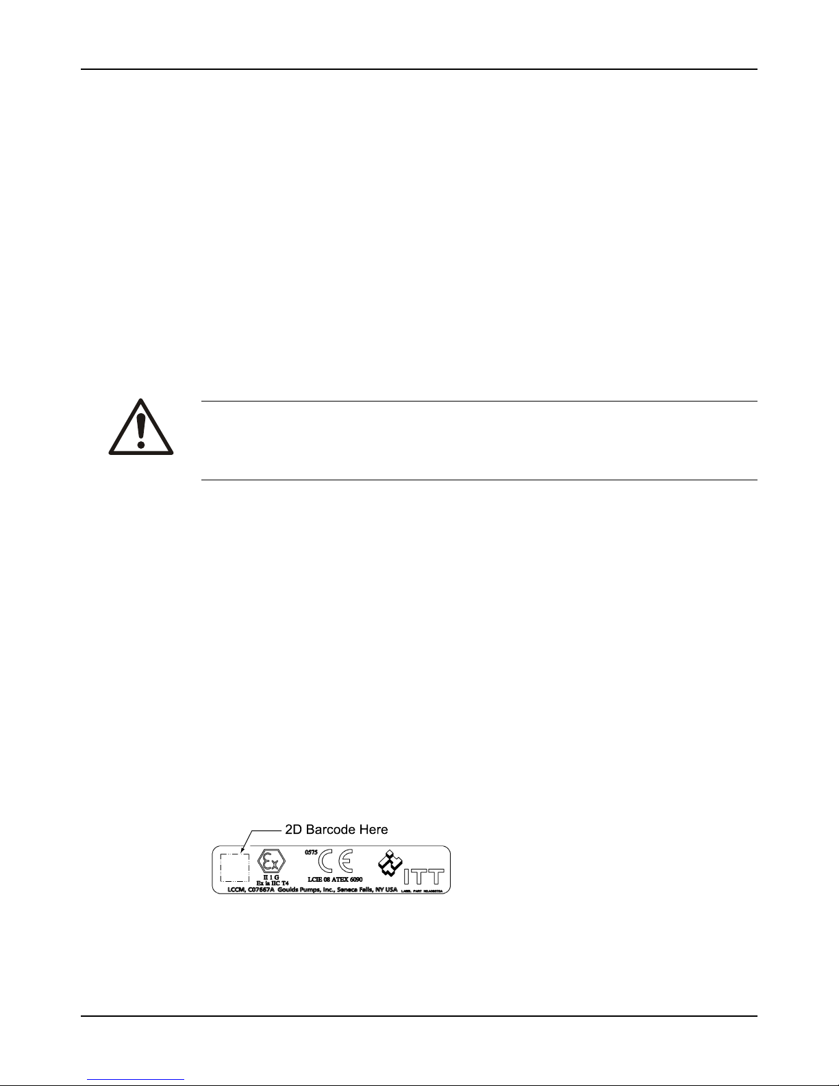
The Ex symbol
The Ex symbol indicates safety regulations for Ex-approved products when used in
atmospheres that are potentially explosive or flammable.
Environmental safety
The work area
Always keep the station clean to avoid and/or discover emissions.
Waste and emissions regulations
Observe these safety regulations regarding waste and emissions:
• Appropriately dispose of all waste.
• Handle and dispose of the processed liquid in compliance with applicable environmental
regulations.
• Clean up all spills in accordance with safety and environmental procedures.
• Report all environmental emissions to the appropriate authorities.
WARNING:
If the product has been contaminated in any way, such as from toxic chemicals or nuclear
radiation, do NOT send the product to ITT unless it has been properly decontaminated.
Electrical installation
For electrical installation recycling requirements, consult your local electric utility.
Page 10

Introduction and Safety
Model 3196 i-FRAME Installation, Operation, and Maintenance Manual8
Recycling guidelines
Always follow local laws and regulations regarding recycling.
User safety
General safety rules
These safety rules apply:
• Always keep the work area clean.
• Pay attention to the risks presented by gas and vapors in the work area.
• Avoid all electrical dangers. Pay attention to the risks of electric shock or arc flash hazards.
• Always bear in mind the risk of drowning, electrical accidents, and burn injuries.
Safety equipment
Use safety equipment according to the company regulations. Use this safety equipment within
the work area:
• Helmet
• Safety goggles, preferably with side shields
• Protective shoes
• Protective gloves
• Gas mask
• Hearing protection
• First-aid kit
• Safety devices
Electrical connections
Electrical connections must be made by certified electricians in compliance with all international, national, state, and local regulations. For more information about requirements, see sections
dealing specifically with electrical connections.
Precautions before work
Observe these safety precautions before you work with the product or are in connection with
the product:
• Provide a suitable barrier around the work area, for example, a guard rail.
• Make sure that all safety guards are in place and secure.
• Make sure that you have a clear path of retreat.
• Make sure that the product cannot roll or fall over and injure people or damage property.
• Make sure that the lifting equipment is in good condition.
• Use a lifting harness, a safety line, and a breathing device as required.
• Allow all system and pump components to cool before you handle them.
• Make sure that the product has been thoroughly cleaned.
• Disconnect and lock out power before you service the pump.
• Check the explosion risk before you weld or use electric hand tools.
Precautions during work
Observe these safety precautions when you work with the product or are in connection with the
product:
CAUTION:
Failure to observe the instructions contained in this manual could result in personal injury and
property damage, and may void the warranty. Read this manual carefully before installing and
using the product.
Page 11
Introduction and Safety
Model 3196 i-FRAME Installation, Operation, and Maintenance Manual 9
• Never work alone.
• Always wear protective clothing and hand protection.
• Stay clear of suspended loads.
• Always lift the product by its lifting device.
• Beware of the risk of a sudden start if the product is used with an automatic level control.
• Beware of the starting jerk, which can be powerful.
• Rinse the components in water after you disassemble the pump.
• Do not exceed the maximum working pressure of the pump.
• Do not open any vent or drain valve or remove any plugs while the system is pressurized.
Make sure that the pump is isolated from the system and that pressure is relieved before
you disassemble the pump, remove plugs, or disconnect piping.
• Never operate a pump without a properly installed coupling guard.
• The coupling guard used in an ATEX classified environment must be constructed from
a non-sparking material.
Hazardous liquids
The product is designed for use in liquids that can be hazardous to your health. Observe these
rules when you work with the product:
• Make sure that all personnel who work with biologically hazardous liquids are vaccinated
against diseases to which they may be exposed.
• Observe strict personal cleanliness.
• A small amount of liquid will be present in certain areas like the seal chamber.
Wash the skin and eyes
1. Follow these procedures for chemicals or hazardous fluids that have come into contact with
your eyes or your skin:
Condition Action
Chemicals or hazardous
fluids in eyes
1. Hold your eyelids apart forcibly with your fingers.
2. Rinse the eyes with eyewash or running water for at least 15 minutes.
3. Seek medical attention.
Chemicals or hazardous
fluids on skin
1. Remove contaminated clothing.
2. Wash the skin with soap and water for at least 1 minute.
3. Seek medical attention, if necessary.
Ex-approved products
Follow these special handling instructions if you have an Ex-approved unit.
Personnel requirements
These are the personnel requirements for Ex-approved products in potentially explosive
atmospheres:
• All work on the product must be carried out by certified electricians and ITT-authorized
mechanics. Special rules apply to installations in explosive atmospheres.
• All users must know about the risks of electric current and the chemical and physical
characteristics of the gas, the vapor, or both present in hazardous areas.
• Any maintenance for Ex-approved products must conform to international and national
standards (for example, IEC/EN 60079-17).
ITT disclaims all responsibility for work done by untrained and unauthorized personnel.
Product and product handling requirements
These are the product and product handling requirements for Ex-approved products in
potentially explosive atmospheres:
• Only use the product in accordance with the approved motor data.
Page 12
Introduction and Safety
Model 3196 i-FRAME Installation, Operation, and Maintenance Manual10
• The Ex-approved product must never run dry during normal operation. Dry running during
service and inspection is only permitted outside the classified area.
• Before you start work on the product, make sure that the product and the control panel are
isolated from the power supply and the control circuit, so they cannot be energized.
• Do not open the product while it is energized or in an explosive gas atmosphere.
• Make sure that thermal contacts are connected to a protection circuit according to the
approval classification of the product, and that they are in use.
• Intrinsically safe circuits are normally required for the automatic level-control system by the
level regulator if mounted in zone 0.
• The yield stress of fasteners must be in accordance with the approval drawing and the
product specification.
• Do not modify the equipment without approval from an authorized ITT representative.
• Only use parts that are provided by an authorized ITT representative.
Product approval standards
Regular standards
WARNING:
Use of equipment unsuitable for the environment can pose risks of ignition and/or explosion.
Ensure that the code classifications on the pump are compatible with the specific environment
in which the equipment is to be installed. If they are not compatible, do not operate the
equipment and contact an ITT representative before proceeding.
All standard products are approved according to CSA standards in Canada and UL standards
in USA. The drive unit degree of protection follows IP68. See the nameplate for maximum
submersion, according to standard IEC 60529.
All electrical ratings and performance of the motors comply with IEC 600341.
Explosion-proofing standards
All explosion-proof products for use in explosive atmospheres are designed in compliance with
one or more of the following approvals:
• EN, ATEX Directive 94/9/EC
• FM According to NEC
• Class 1 Div 1 Groups “C”, and “D”
• Class 2 Div 1 Groups “E”, “F”, and “G”
• Class 3 Div 1 Hazardous Locations
ATEX/IECEx:
• Group: IIC
• Category: Ex ia
• Temperature Class: T4 (for ambients up to 100ºC)
• ATEX Marking: Ex II 1 G
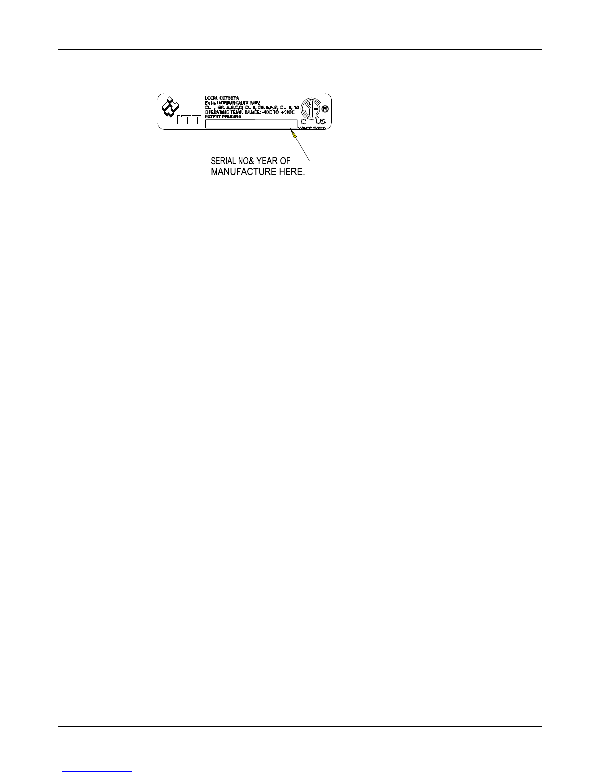
CSA certification
Intrinsically safe for:
• Class I, Div. 1, Groups A, B, C, D
• Class II, Div. 1, Groups E, F, G
Page 13
Introduction and Safety
Model 3196 i-FRAME Installation, Operation, and Maintenance Manual 11
• Class III
• Certified to Canadian and US requirements
Product warranty
Coverage
ITT undertakes to remedy faults in products from ITT under these conditions:
• The faults are due to defects in design, materials, or workmanship.
• The faults are reported to an ITT representative within the warranty period.
• The product is used only under the conditions described in this manual.
• The monitoring equipment incorporated in the product is correctly connected and in use.
• All service and repair work is done by ITT-authorized personnel.
• Genuine ITT parts are used.
• Only Ex-approved spare parts and accessories authorized by ITT are used in Ex-approved
products.
Limitations
The warranty does not cover faults caused by these situations:
• Deficient maintenance
• Improper installation
• Modifications or changes to the product and installation made without consulting ITT
• Incorrectly executed repair work
• Normal wear and tear
ITT assumes no liability for these situations:
• Bodily injuries
• Material damages
• Economic losses
Warranty claim
ITT products are high-quality products with expected reliable operation and long life. However,
should the need arise for a warranty claim, then contact your ITT representative.
Page 14
Transportation and Storage
Model 3196 i-FRAME Installation, Operation, and Maintenance Manual12
Transportation and Storage
Inspect the delivery
Inspect the package
1. Inspect the package for damaged or missing items upon delivery.
2. Note any damaged or missing items on the receipt and freight bill.
3. File a claim with the shipping company if anything is out of order.
If the product has been picked up at a distributor, make a claim directly to the distributor.
Inspect the unit
1. Remove packing materials from the product.
Dispose of all packing materials in accordance with local regulations.
2. Inspect the product to determine if any parts have been damaged or are missing.
3. If applicable, unfasten the product by removing any screws, bolts, or straps.
For your personal safety, be careful when you handle nails and straps.
4. Contact your sales representative if anything is out of order.
Transportation guidelines
Pump handling
WARNING:
Dropping, rolling or tipping units, or applying other shock loads, can cause property damage
and personal injury. Ensure that the unit is properly supported and secure during lifting and
handling.
CAUTION:
Risk of injury or equipment damage from use of inadequate lifting devices. Ensure lifting
devices (such as chains, straps, forklifts, cranes, etc.) are rated to sufficient capacity.
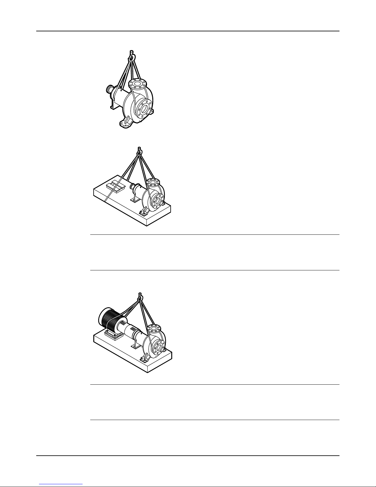
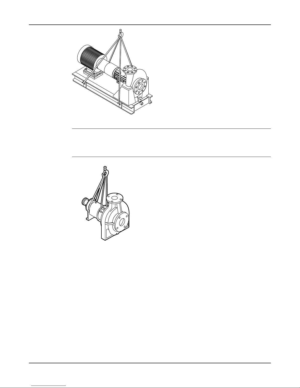
Lifting methods
WARNING:
• Risk of serious personal injury or equipment damage. Proper lifting practices are critical to
safe transport of heavy equipment. Ensure that practices used are in compliance with all
applicable regulations and standards.
• Safe lifting points are specifically identified in this manual. It is critical to lift the equipment
only at these points. Integral lifting eyes or eye bolts on pump and motor components are
intended for use in lifting the individual components only.
• Lifting and handling heavy equipment poses a crush hazard. Use caution during lifting and
handling and wear appropriate Personal Protective Equipment (PPE, such as steel-toed
shoes, gloves, etc.) at all times. Seek assistance if necessary.
Table 1: Methods
Pump type Lifting method
A bare pump without lifting handles
Use a suitable sling attached properly to solid points like the casing,
the flanges, or the frames.
A bare pump with lifting handles Liftthepumpbythehandles.
A base-mounted pump Use slings under the pump casing and the drive unit, or under the base
rails.
Page 15
Transportation and Storage
Model 3196 i-FRAME Installation, Operation, and Maintenance Manual 13
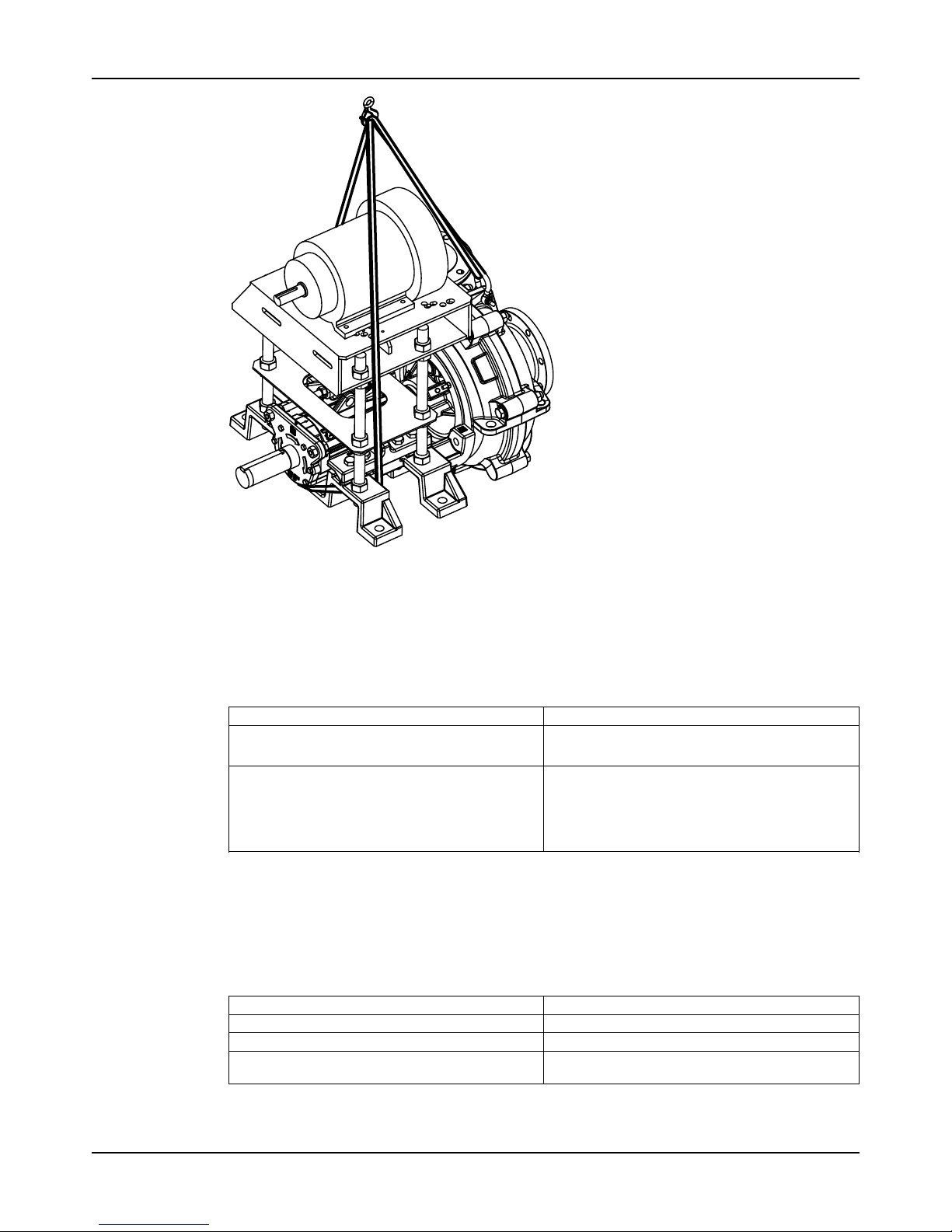
Examples
Figure 1: Example of a proper lifting method
NOTICE:
Do not use this method to lift a Polyshield ANSI Combo with the pump and motor mounted.
These items are not designed to handle the heavy weight of the Polyshield system. Doing so
may result in equipment damage.
Figure 2: Example of a proper lifting method
NOTICE:
Do not use this method to lift a Polyshield ANSI Combo with the pump and motor mounted.
These items are not designed to handle the heavy weight of the Polyshield system. Doing so
may result in equipment damage.
Figure 3: Example of a proper lifting method
Page 16
Transportation and Storage
Model 3196 i-FRAME Installation, Operation, and Maintenance Manual14
Figure 4: Example of a proper lifting method
NOTICE:
When lifting a unit for which a strap cannot be secured at the suction flange, secure the strap
through the frame/frame adapter. Securing at the frame adapter will prevent slipping of the
strap and possible equipment damage.
Figure 5: Example of a proper lifting method with a strap secured around the frame adapter
Page 17
Transportation and Storage
Model 3196 i-FRAME Installation, Operation, and Maintenance Manual 15
Figure 6: Example of offset overhead motor mount pump proper lifting method
Storage guidelines
Pump storage requirements
Storage requirements depend on the amount of time that you store the unit. The normal
packaging is designed only to protect the unit during shipping.
Length of time in storage Storage requirements
Upon receipt/short-term (less than six months)
• Store in a covered and dry location.
• Store the unit free from dirt and vibrations.
Long-term (more than six months)
• Store in a covered and dry location.
• Store the unit free from heat, dirt, and vibrations.
• Rotate the shaft by hand several times at least
every three months.
Treat bearing and machined surfaces so that they are well preserved. Refer to drive unit and
coupling manufacturers for their long-term storage procedures.
You can purchase long-term storage treatment with the initial unit order or you can purchase it
and apply it after the units are already in the field. Contact your local ITT sales representative.
Frostproofing
Table 2: Situations when the pump is or is not frostproof
Situation Condition
Operating The pump is frostproof.
Immersed in a liquid The pump is frostproof.
Lifted out of a liquid into a temperature below
freezing
The impeller might freeze.
Page 18
Product Description
Model 3196 i-FRAME Installation, Operation, and Maintenance Manual16
Product Description
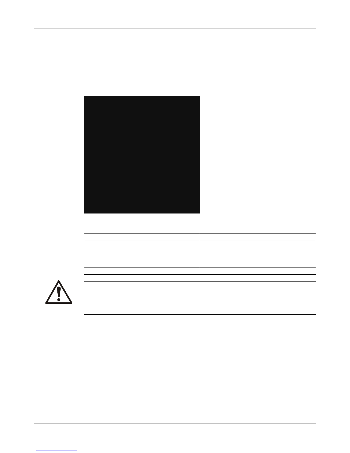
General description 3196
The 3196 is a horizontal overhung, open impeller, centrifugal pump. This pump is ANSI B73.1
compliant.
The model is based on 5 power ends and 29 hydraulic sizes.
Figure 7: 3196 pump
This table shows the number of hydraulic sizes available for each drive-unit size group.
Drive-unit size group Number of hydraulic sizes
STi 5
MTi 15
LTi 15
XLT-i 5
i-17 4
WARNING:
Use of equipment unsuitable for the environment can pose risks of ignition and/or explosion.
Ensure that the code classifications on the pump are compatible with the specific environment
in which the equipment is to be installed. If they are not compatible, do not operate the
equipment and contact an ITT representative before proceeding.
Page 19
Product Description
Model 3196 i-FRAME Installation, Operation, and Maintenance Manual 17
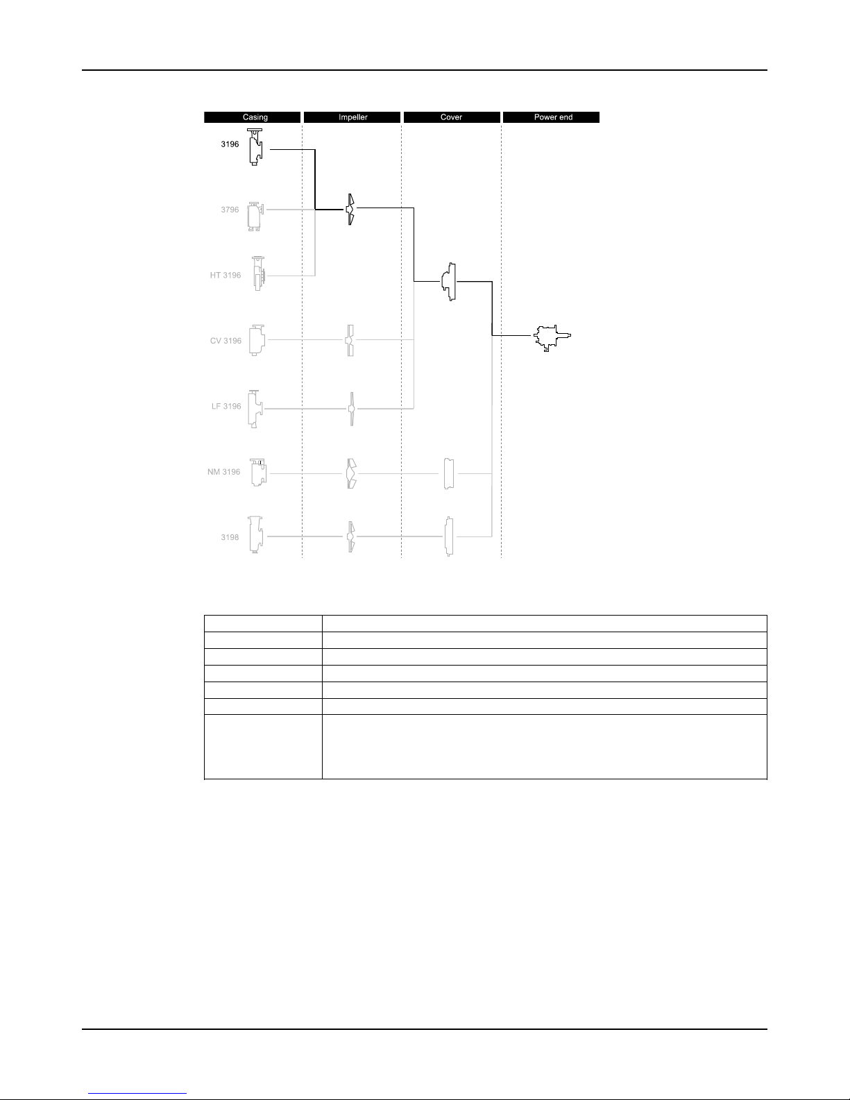
Part description 3196
Figure 8: 3196 part description
Table 3: Casing
This table describes the pump casing parts.
Part Description
Discharge Top-centerline
Casing ventilation Self venting
Gasket Fully confined
Mounting method Integral foot support for maximum resistance to misalignment due to piping loads.
Standard flange ANSI flat-faced serrated flange
Optional flanges One of the following flanges can be used:
• ANSI class 150 raised-face serrated flange
• ANSI class 300 flat-face serrated flange
• ANSI class 300 raised-face serrated flange
Impeller
The impeller is
• fully open
• threaded onto the shaft
The threads are sealed from the pumped liquid by a PTFE O-ring for the 3196.
Cover
Standard
• Stuffing Box cover designed for packing or a mechanical seal
• BigBore or TaperBore® PLUS seal chambers designed for improved performance of
mechanical seals
Page 20

Product Description
Model 3196 i-FRAME Installation, Operation, and Maintenance Manual18
Optional sealing design
• a dynamic seal is available which uses a repeller to pump liquid out of the stuffing box
while the pump operates. A static seal prevents leakage when the pump is shut down.
Table 4: Power end
This table describes the main parts of the power end.
Part Description
Frame adapter The ductile iron frame adapter has
• a machined rabbet fit to the seal chamber/ stuffing box cover
• a precision dowel pin fit to the bearing frame.
Power end
• Flood-oil lubrication is standard.
• Oil-mist, regreasable and greased-for-life options are available.
• The oil level is checked through a sight glass.
• The power end is sealed with labyrinth seals.
• The power end is made in the following sizes:
• STi
• MTi
• LTi
• XLT-i
• i-17
Shaft The shaft is available with or without a sleeve.
Bearings The inboard bearing
• carries only radial loads.
• is free to float axially in the frame.
• is a single-row deep-groove ball bearing
The outboard bearing
• is shouldered and locked to the shaft and housing to enable it to carry radial
and thrust loads.
• is a double-row angular-contact bearing, except for the LTi which uses a pair
of single-row angular-contact ball bearings mounted back-to-back.
General description i-ALERT®Condition Monitor
Description
The i-ALERT®2 Condition Monitor is a compact, battery-operated monitoring device that
continuously measures the vibration and temperature of the pump power end. The condition
monitor uses blinking red LEDs to alert the pump operator when the pump exceeds pre-set
vibration and temperature limits. This allows the pump operator to make changes to the
process or the pump before a catastrophic failure occurs. The condition monitor is also
equipped with a single green LED to indicate when it is operational and has sufficient battery
life. (i-ALERT®2) Bluetooth Equipment Health Monitor option available. The i-ALERT®2 monitor
allows customers to identify potential problems before they become costly failures. It tracks
vibration, temperature and run-time hours and wirelessly syncs the data with a smart phone or
tablet the i-ALERT®2 mobile app. More information available on http://www.ittproservices.com/
aftermarket-products/monitoring/i-alert2/i-ALERT2.com).
Software License Agreement
BY USING THE i-ALERT®2 CONDITION MONITOR, YOU AGREE TO BE BOUND BY THE
TERMS AND CONDITIONS OF THE FOLLOWING LICENSE AGREEMENT. PLEASE READ
THIS AGREEMENT CAREFULLY.
ITT Corporation and its subsidiaries, affiliates, either directly, or through its authorized
sublicensees ("ITT") grants you a limited, non-exclusive license to use the software embedded
in this device ("Software") in binary executable form in the normal operation of the i-ALERT®2
condition monitor for monitoring the condition of an Goulds Pump Inc. model. Title, ownership
rights, and intellectual property rights in and to the Software remain in ITT or its third-party
Page 21

Product Description
Model 3196 i-FRAME Installation, Operation, and Maintenance Manual 19
providers. You agree that this license agreement does not need to be signed for it to take
effect.
You acknowledge that this Software is the property of ITT and is protected under United States
of America copyright laws and international copyright treaties. You further acknowledge that
the structure, organization, and code of the Software are valuable trade secrets of ITT and/or
its third-party providers and that the Software in source code form remains a valuable trade
secret of ITT. You agree not to decompile, disassemble, modify, reverse assemble, reverse
engineer, or reduce to human readable form the Software or any part thereof or create any
derivative works based on the Software. You agree not to export or re-export the Software to
any country in violation of the export control laws of the United States of America.
Alarm mode
The condition monitor enters alarm mode when either vibration or temperature limits are
exceeded over two consecutive readings within a ten minute period. Alarm mode is indicated
with two red flashing LEDs within two second intervals.
Temperature and vibration limits
Variable Limit
Temperature 91°C | 195°F
Vibration 100%increaseoverthebaselinelevel
Battery life
The i-ALERT®2 Condition Monitor battery is not replaceable. You must replace the entire
unit once the battery runs out of power.
The battery life is not covered as part of the standard pump warranty.
This table shows the average condition monitor battery life under normal and alarm-mode operating
conditions.
Condition monitor operational state Battery life
Normal operating and environmental conditions Three to five years
Alarm mode One year
Page 22
Product Description
Model 3196 i-FRAME Installation, Operation, and Maintenance Manual20
Nameplate information
Important information for ordering
Every pump has nameplates that provide information about the pump. The nameplates are
located on the casing and the bearing frame.
When you order spare parts, identify this pump information:
• Model
• Size
• Serial number
• Item numbers of the required parts
Refer to the nameplate on the pump casing for most of the information. See Parts List for item
numbers.
Nameplate types
Nameplate Description
Pump casing
Pump
Provides information about the hydraulic characteristics of the pump.
The formula for the pump size is: Discharge x Suction - Nominal Maximum Impeller Diameter in inches.
(Example: 2x3-8)
Bearing frame Provides information about the lubrication system used.
ATEX If applicable, your pump unit might have an ATEX nameplate affixed to the pump, the baseplate, or the
discharge head. The nameplate provides information about the ATEX specifications of this pump.
IECEx If applicable, your pump unit might have the following IECEx nameplate affixed to the pump and/or
baseplate. The nameplate provides information about the IECEx specifications of this pump.
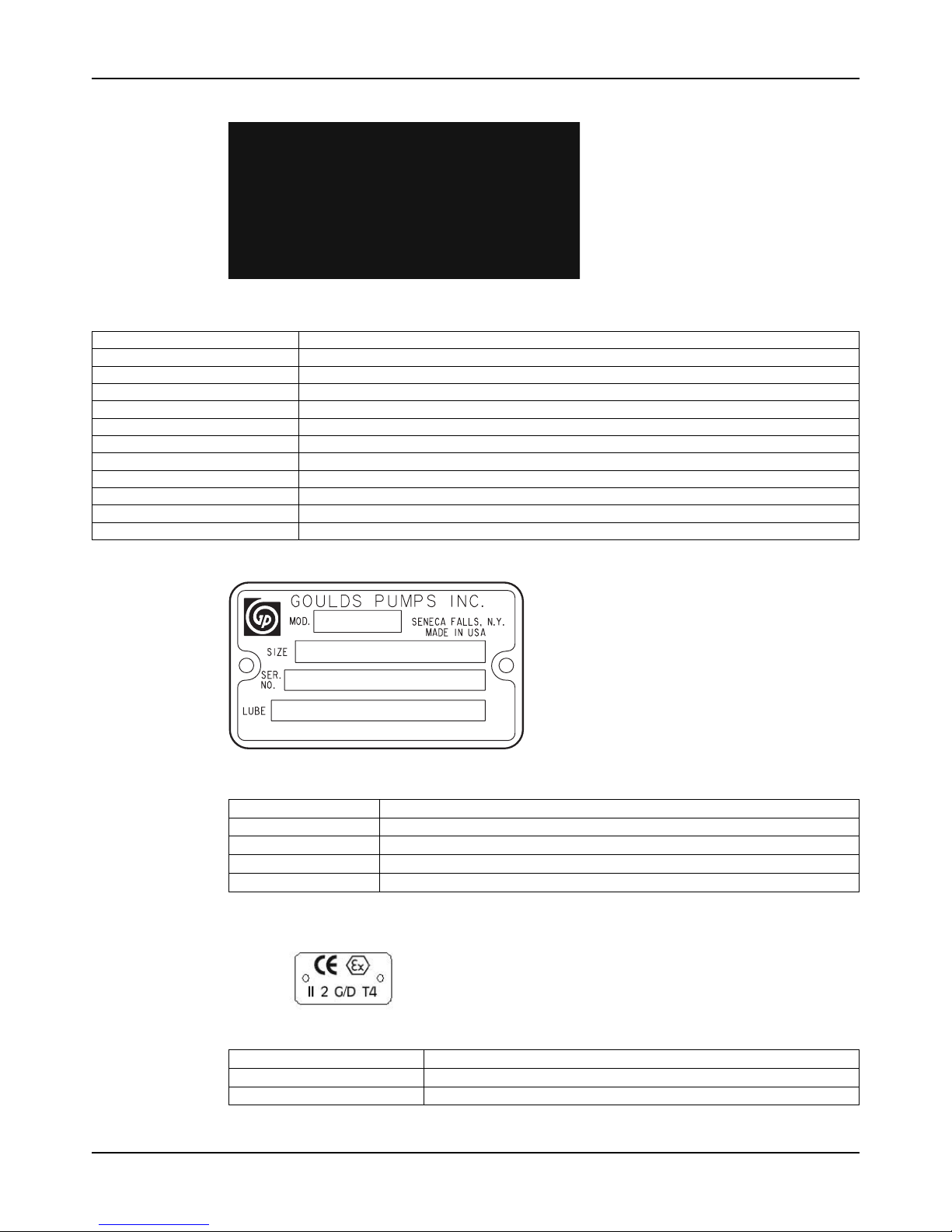
Nameplate on the pump casing using English units
Figure 9: Nameplate on the pump casing using English units
Table 5: Explanation of nameplate on the pump casing
Nameplate field Explanation
IMPLR. DIA. Impeller diameter, in inches
MAX. DIA. Maximum impeller diameter, in inches
GPM Ratedpumpflow,ingallonsperminute
FT HD Rated pump head, in feet
RPM Rated pump speed, revolutions per minute
MOD. Pump model
SIZE Size of the pump
STD. NO. ANSIstandarddesignation
MAT L. CONST. Material of which the pump is constructed
SER. NO. Serial number of the pump
MAX DSGN PSI @
100ºF
Maximum pressure at 100ºF according to the pump design
Page 23
Product Description
Model 3196 i-FRAME Installation, Operation, and Maintenance Manual 21
Nameplate on the pump casing using metric units
Figure 10: Metric units - nameplate on pump casing
Table 6: Explanation of the nameplate on the pump casing
Nameplate field Explanation
IMPLR. DIA. Impellerdiameter
MAX. DIA. Maximum impeller diameter
M3/HR Rated pump flow, in cubic meters per hour
M HD Rated pump head, in meters
RPM Rated pump speed, in revolutions per minute
MOD. Pump model
SIZE Size of the pump
STD. NO. ANSI standard designation
MAT L. CONST Material of which the pump is constructed
SER. NO. Serialnumberofthepump
MAX. DSGN KG/CM3@ 20°C Kilograms per cubic centimeter at 20°C
Nameplate on the bearing frame
Figure 11: Nameplate on the bearing frame
Table 7: Explanation of the nameplate on the bearing frame
Nameplate field Explanation
BRG. O. B. Outboard bearing designation
BRG. I. B. Inboard bearing designation
S/N Serial number of the pump
LUBE Lubricant, oil or grease
ATEX nameplate
Figure 12: ATEX nameplate
Nameplate field Explanation
II Group 2
2 Category 2
Page 24

Product Description
Model 3196 i-FRAME Installation, Operation, and Maintenance Manual22
Nameplate field Explanation
G/D Pumpcanbeusedwhengasanddustarepresent
T4 Temperature class
WARNING:
Use of equipment unsuitable for the environment can pose risks of ignition and/or explosion.
Ensure that the code classifications on the pump are compatible with the specific environment
in which the equipment is to be installed. If they are not compatible, do not operate the
equipment and contact an ITT representative before proceeding.
Page 25
Installation
Model 3196 i-FRAME Installation, Operation, and Maintenance Manual 23
Installation
Preinstallation
Precautions
WARNING:
• When installing in a potentially explosive environment, ensure that the motor is
properly certified.
• All equipment being installed must be properly grounded to prevent unexpected
discharge. Discharge can cause equipment damage, electric shock, and result in serious
injury. Test the ground lead to verify it is connected correctly.
NOTICE:
• Electrical connections must be made by certified electricians in compliance with all
international, national, state and local regulations.
• Supervision by an authorized ITT representative is recommended to ensure proper
installation. Improper installation may result in equipment damage or decreased performance.
Pump location guidelines
WARNING:
Safe lifting points are specifically identified in this manual. It is critical to lift the equipment only
at these points. Integral lifting eyes or eye bolts on pump and motor components are intended
for use in lifting the individual components only.
Guideline Explanation/comment
Keep the pump as close to the liquid
source as practically possible.
This minimizes the friction loss and keeps the suction piping
as short as possible.
Make sure that the space around the
pump is sufficient.
This facilitates ventilation, inspection, maintenance, and service.
If you require lifting equipment such as a
hoist or tackle, make sure that there is
enough space above the pump.
This makes it easier to properly use the lifting equipment and
safely remove and relocate the components to a safe
location.
Protect the unit from weather and water
damage due to rain, flooding, and freezing
temperatures.
This is applicable if nothing else is specified.
Do not install and operate the equipment
in closed systems unless the system is
constructed with properly-sized safety devices and control devices.
Acceptable devices:
• Pressure relief valves
• Compression tanks
• Pressure controls
• Temperature controls
• Flow controls
If the system does not include these devices, consult the
engineer or architect in charge before you operate the pump.
Take into consideration the occurrence of
unwanted noise and vibration.
The best pump location for noise and vibration absorption is
on a concrete floor with subsoil underneath.
If the pump location is overhead, undertake special precautions to reduce possible noise transmission.
Consider a consultation with a noise specialist.
Page 26

Installation
Model 3196 i-FRAME Installation, Operation, and Maintenance Manual24
Foundation requirements
Requirements
• The foundation must be able to absorb any type of vibration and form a permanent, rigid
support for the unit.
• The location and size of the foundation bolt holes must match those shown on the
assembly drawing provided with the pump data package.
• The foundation must weigh between two and three times the weight of the pump.
• Provide a flat, substantial concrete foundation in order to prevent strain and distortion
when you tighten the foundation bolts.
Sleeve-type bolts
1. Baseplate
2. Shims or wedges
3. Foundation
4. Sleeve
5. Dam
6. Bolt
Figure 13: Sleeve type bolts
J-type bolts
1. Baseplate
2. Shims or wedges
3. Foundation
4. Dam
5. Bolt
Figure 14: J-type bolts
Baseplate-mounting procedures
Prepare the baseplate for mounting
1. Remove all the attached equipment from the baseplate.
2. Clean the underside of the baseplate completely.
3. If applicable, coat the underside of the baseplate with an epoxy primer.
Page 27

Installation
Model 3196 i-FRAME Installation, Operation, and Maintenance Manual 25
Use an epoxy primer only if you used an epoxy-based grout.
4. Remove the rust-proofing coat from the machined mounting pads using an appropriate
solvent.
5. Remove water and debris from the foundation-bolt holes.
Install the baseplate using shims or wedges
Required tools:
• Two sets of shims or wedges for each foundation bolt
• Two machinist's levels
• Baseplate-leveling worksheet
This procedure is applicable to cast iron and fabricated steel baseplates.
1. If you use sleeve-type bolts, fill the bolt sleeves with packing material or rags to prevent
grout from entering the bolt holes.
2. Put the sets of wedges or shims on each side of each foundation bolt.
The sets of wedges should have a height of between 19 mm | 0.75 in. and 38 mm | 1.50 in.
1. Shims or wedges
Figure 15: Top view
1. Shims or wedges
Figure 16: Side view
3. Lower the baseplate carefully onto the foundation bolts.
4. Put the machinist's levels across the mounting pads of the driver and the mounting pads of
the pump.
NOTICE:
Remove all dirt from the mounting pads in order to ensure that the correct leveling is
achieved. Failure to do so can result in equipment damage or decreased performance.
5. Level the baseplate both lengthwise and across by adding or removing shims or moving the
wedges.
These are the leveling tolerances:
• A maximum difference of 3.2 mm | 0.125 in. lengthwise
• A maximum difference of 1.5 mm | 0.059 in. across
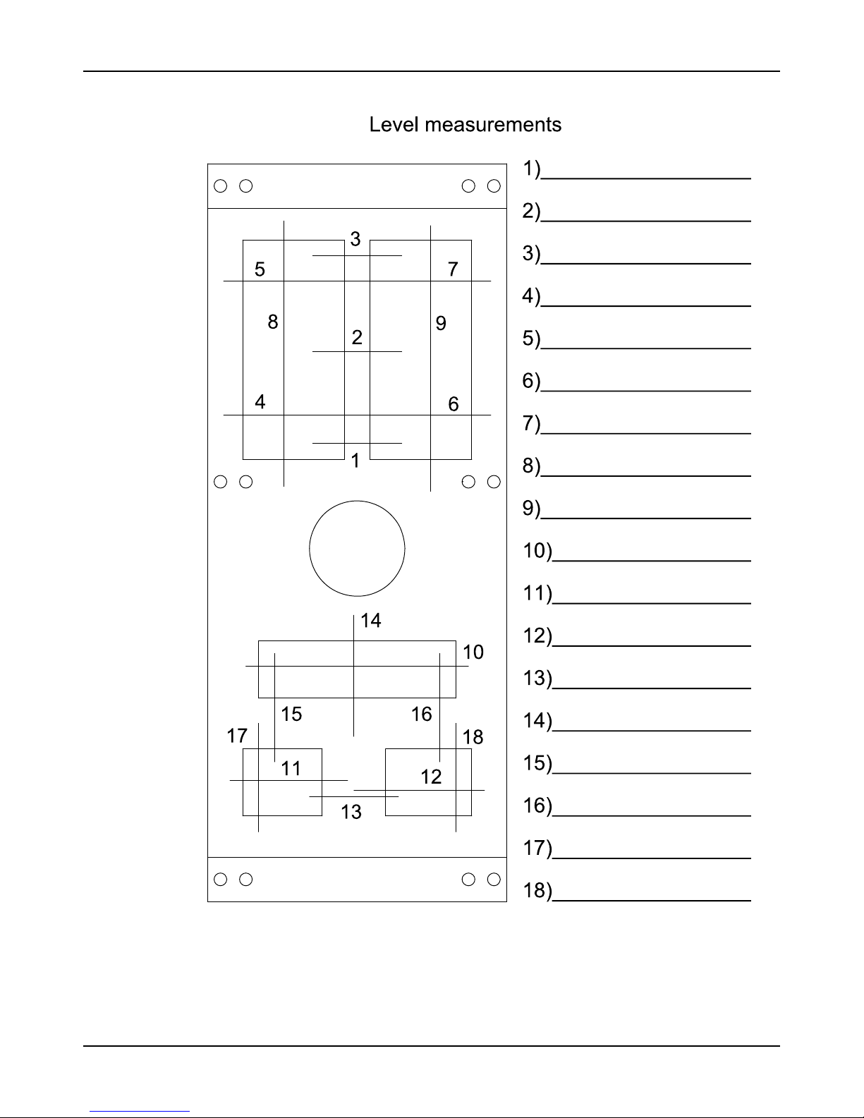
You can use the baseplate-leveling worksheet when you take the readings.
6. Hand-tighten the nuts for the foundation.
Page 28
Installation
Model 3196 i-FRAME Installation, Operation, and Maintenance Manual26
Install the baseplate using jackscrews
Tools required:
• Anti-seize compound
• Jackscrews
• Bar stock
• Two machinist's levels
• Baseplate-leveling worksheet
This procedure is applicable to the feature-fabricated steel baseplate and the advantage base
baseplate.
1. Apply an anti-seize compound on the jackscrews.
The compound makes it easier to remove the screws after you grout.
2. Lower the baseplate carefully onto the foundation bolts and perform these steps:
a) Cut the plates from the bar stock and chamfer the edges of the plates in order to reduce
stress concentrations.
b) Put the plates between the jackscrews and the foundation surface.
c) Use the four jackscrews in the corners in order to raise the baseplate above the
foundation.
Make sure that the distance between the baseplate and the foundation surface is
between 19 mm | 0.75 in. and 38 mm | 1.50 in.
d) Make sure that the center jackscrews do not touch the foundation surface yet.
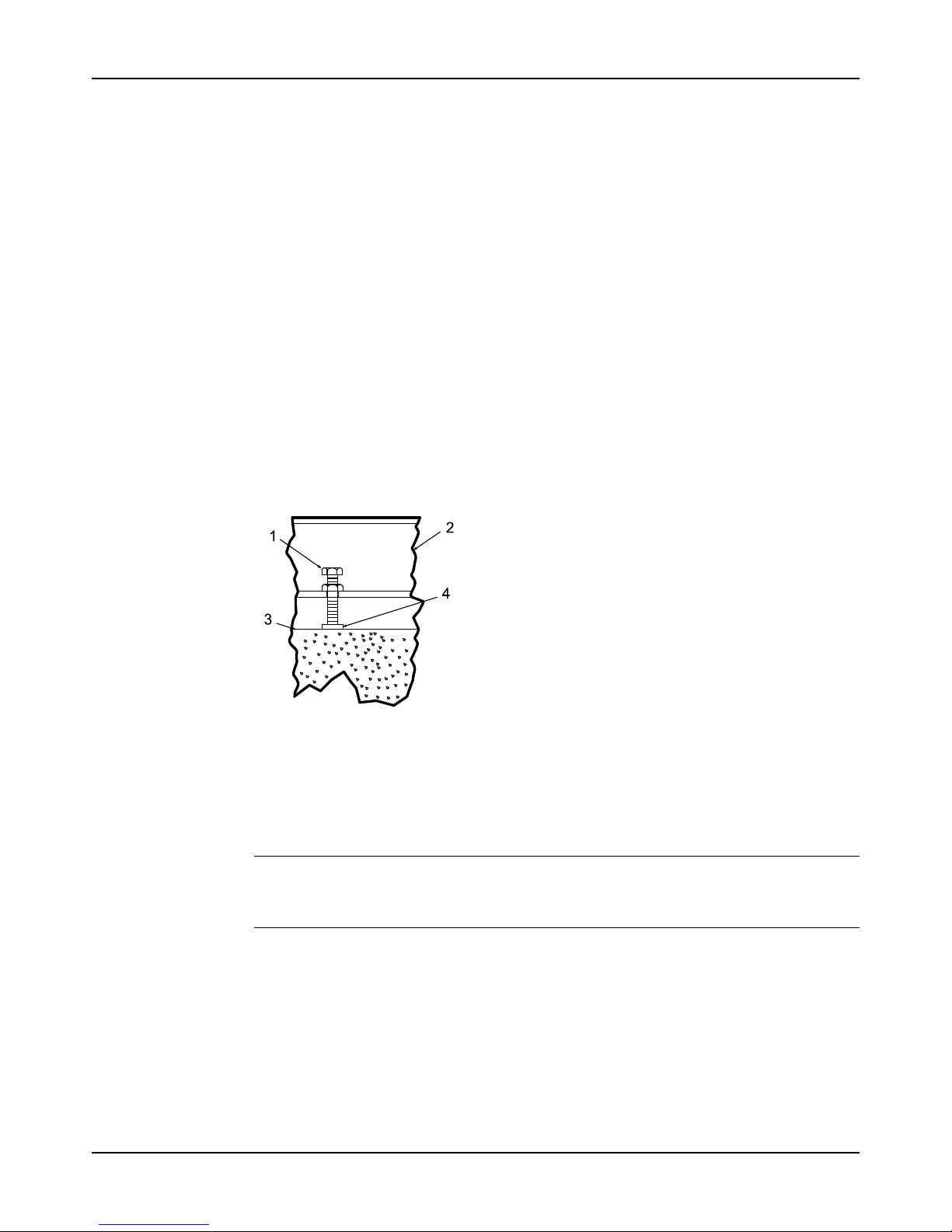
1. Jackscrew
2. Baseplate
3. Foundation
4. Plate
Figure 17: Jackscrews
3. Level the driver mounting pads:
NOTICE:
Remove all dirt from the mounting pads in order to ensure that the correct leveling is
achieved. Failure to do so can result in equipment damage or decreased performance.
a) Put one machinist's level lengthwise on one of the two pads.
b) Put the other machinist's level across the ends of the two pads.
Page 29
Installation
Model 3196 i-FRAME Installation, Operation, and Maintenance Manual 27
c) Level the pads by adjusting the four jackscrews in the corners.
Make sure that the machinist's level readings are as close to zero as possible, both
lengthwise and across.
Use the baseplate-leveling worksheet when you take the readings.
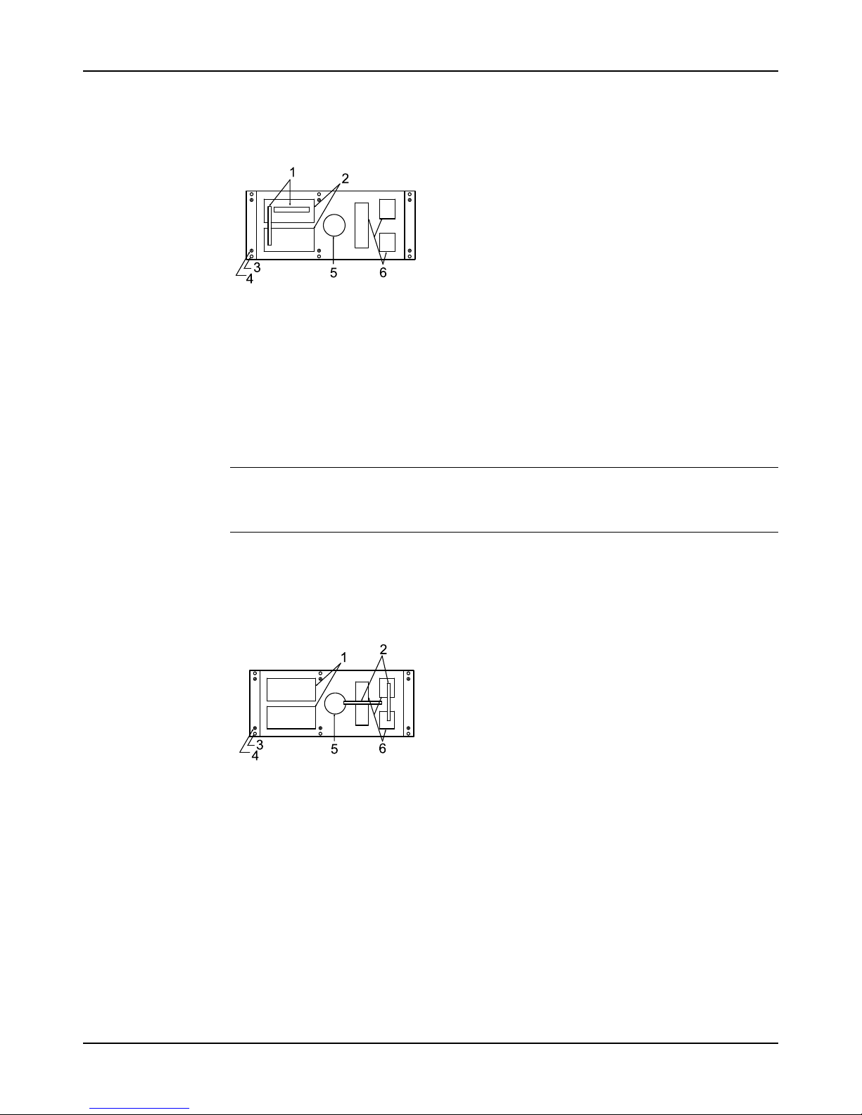
1. Machinist's levels
2. Driver's mounting pads
3. Foundation bolts
4. Jackscrews
5. Grout hole
6. Pump's mounting pads
Figure 18: Level driver mounting pads
4. Turn the center jackscrews down so that they rest on their plates on the foundation surface.
5. Level the pump mounting pads:
NOTICE:
Remove all dirt from the mounting pads in order to ensure that the correct leveling is
achieved. Failure to do so can result in equipment damage or decreased performance.
a) Put one machinist's level lengthwise on one of the two pads.
b) Put the other level across the center of the two pads.
c) Level the pads by adjusting the four jackscrews in the corners.
Make sure that the machinist's level readings are as close to zero as possible, both
lengthwise and across.
1. Driver's mounting pads
2. Machinist's levels
3. Foundation bolts
4. Jackscrews
5. Grout hole
6. Pump's mounting pads
Figure 19: Level pump mounting pads
6. Hand-tighten the nuts for the foundation bolts.
7. Check that the driver's mounting pads are level and adjust the jackscrews and the
foundation bolts if necessary.
The correct level measurement is a maximum of 0.0167 mm/m | 0.002 in./ft .
Page 30

Installation
Model 3196 i-FRAME Installation, Operation, and Maintenance Manual28
Install the baseplate using spring mounting
NOTICE:
The spring-mounted baseplate is designed only to support piping loads from thermal
expansion. Ensure that the suction and discharge piping are supported individually. Failure to
do so may result in equipment damage.
The foundation pads are not provided with the baseplate. Make sure that the foundation pads
are 316 stainless-steel plates, which have a 16-20 micro-inch surface finish.
Before you start this procedure, make sure that the foundation pads are correctly installed on
the foundation/floor (see the manufacturer's instructions).
1. Put the baseplate on a support above the foundation/floor.
Make sure that there is enough space between the baseplate and the foundation/floor in
order to install the spring assemblies.
2. Install the lower part of the spring assembly:
a) Screw the lower jam nut onto the spring stud.
b) Screw the lower adjusting nut onto the spring-stud, on top of the jam nut.
c) Set the lower adjusting nut to the correct height.
The correct height depends on the required distance between the foundation/floor and
the baseplate.
d) Put a washer, a follower, a spring, and one more follower onto the lower adjusting nut.
3. Install the spring assembly on the baseplate:
a) Insert the spring assembly into the baseplate's anchorage hole from below.
b) Put a follower, a spring, another follower, and a washer onto the spring stud.
c) Fasten the spring assembly with the upper adjusting nut by hand.
4. Thread the upper jam nut onto the spring stud by hand.
5. Repeat steps 2 through 4 for all the spring assemblies.
6. Lower the baseplate so that the spring assemblies fit into the foundation pads.
7. Level the baseplate and make the final height adjustments:
a) Loosen the upper jam nuts and adjusting nuts.
b) Adjust the height and level the baseplate by moving the lower adjusting nuts.
c) When the baseplate is level, tighten the top adjusting nuts so that the top springs are
not loose in their followers.
8. Fasten the lower and upper jam nuts on each spring assembly.
Page 31
Installation
Model 3196 i-FRAME Installation, Operation, and Maintenance Manual 29
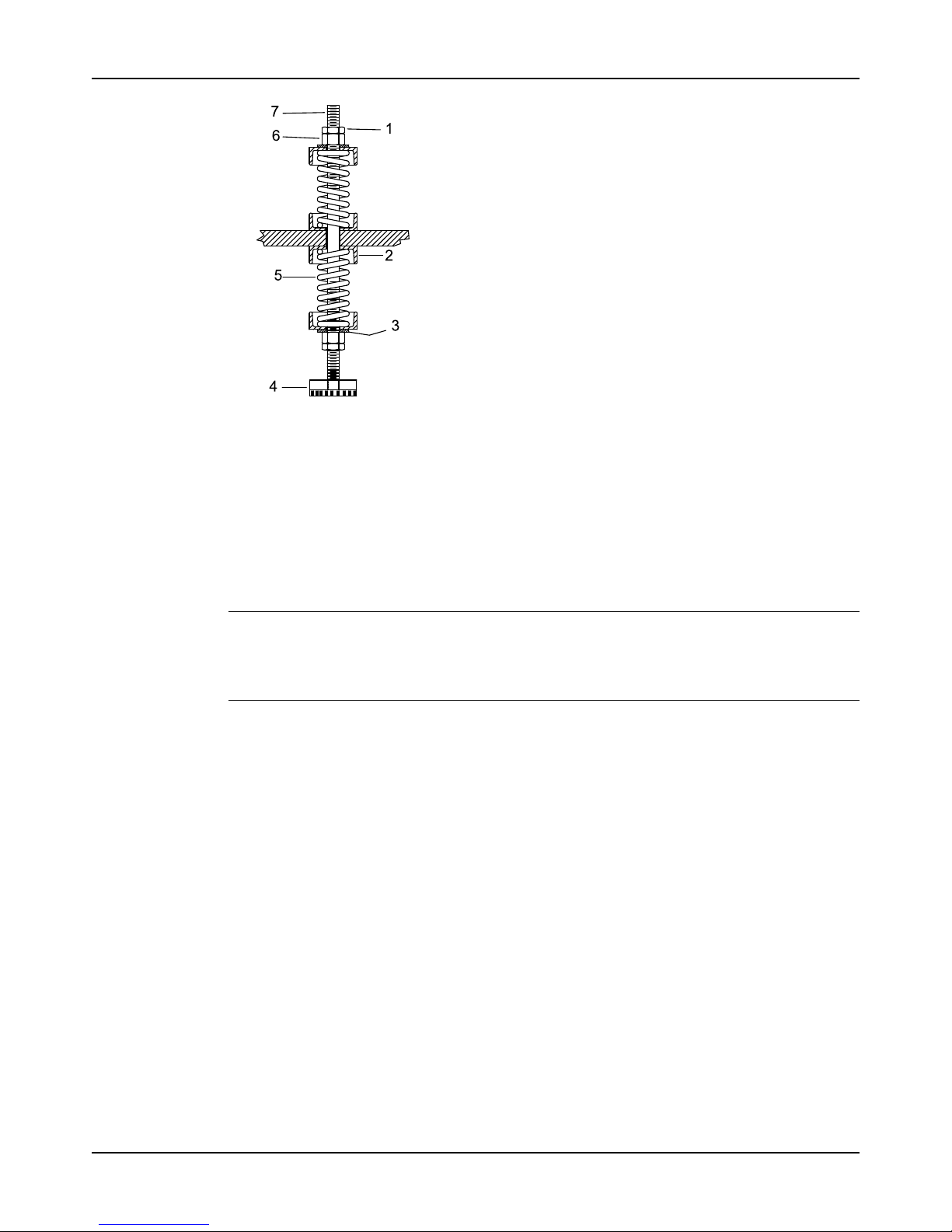
1. Upper jam nut
2. Follower
3. Washer
4. Foundation pads
5. Spring
6. Upper adjusting nut
7. Spring stud
Figure 20: Example of an installed spring assembly
Install the baseplate using stilt mounting
NOTICE:
The stilt-mounted baseplate is not designed to support static piping loads. Ensure that the
suction and discharge piping are supported individually. Failure to do so may result in
equipment damage.
1. Put the baseplate on a support above the foundation/floor.
Make sure that there is enough space between the baseplate and the foundation/floor to
install the stilts.
2. Install the lower part of the stilt assembly:
a) Screw the lower jam nut and adjusting nut onto the stilt.
b) Set the lower adjusting nut to the correct height.
The correct height depends on the required distance between the foundation/floor and
the baseplate.
c) Put a washer onto the lower adjusting- nut.
3. Install the stilt assembly on the baseplate:
a) Insert the stilt assembly into the baseplate's anchorage hole from below.
b) Put a washer onto the stilt.
c) Fasten the stilt assembly with the upper adjusting nut by hand.
4. Screw the upper jam nut onto the stilt by hand.
5. Repeat steps 2 through 4 for all the stilt assemblies.
6. Lower the baseplate so that the stilts fit into the foundation cups.
7. Level the baseplate and make the final height adjustments:
a) Loosen the upper jam nuts and adjusting nuts.
b) Adjust the height and level the baseplate by moving the lower adjusting nuts.
c) When the baseplate is level, tighten the top adjusting nuts.
8. Fasten the lower and upper jam nuts on each stilt.
Page 32
Installation
Model 3196 i-FRAME Installation, Operation, and Maintenance Manual30
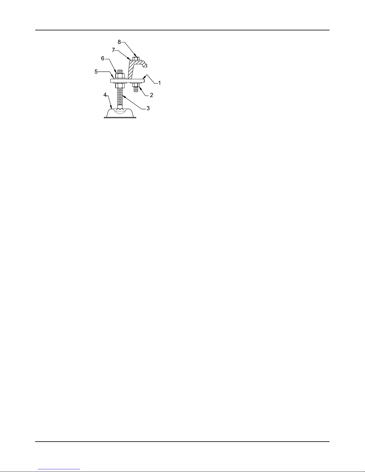
1. Mounting plate
2. Mounting nut
3. Stilt bolt
4. Foundation cups
5. Washer
6. Upper adjustment nut
7. Mounting washer
8. Mounting bolt
Figure 21: Example of an installed stilt assembly
Page 33
Installation
Model 3196 i-FRAME Installation, Operation, and Maintenance Manual 31
Baseplate-leveling worksheet
Page 34
Installation
Model 3196 i-FRAME Installation, Operation, and Maintenance Manual32
Install the pump, driver, and coupling
1. Mount and fasten the pump on the baseplate. Use applicable bolts.
2. Mount the driver on the baseplate . Use applicable bolts and hand tighten.
3. Install the coupling.
See the installation instructions from the coupling manufacturer.
Pump-to-driver alignment
Precautions
WARNING:
• Misalignment can cause decreased performance, equipment damage, and even catastrophic failure of frame-mounted units leading to serious injury. Proper alignment is the
responsibility of the installer and the user of the unit. Check the alignment of all drive
components prior to operating the unit.
• Follow the coupling installation and operation procedures from the coupling manufactur-
er.
• Failure to disconnect and lock out driver power may result in serious physical injury or
death. Always disconnect and lock out power to the driver before performing any
installation or maintenance tasks.
• Electrical connections must be made by certified electricians in compliance with all
international, national, state, and local rules.
• Refer to driver/coupling/gear manufacturer's installation and operation manuals (IOM)
for specific instructions and recommendations.
Alignment checks
When to perform alignment checks
You must perform alignment checks under these circumstances:
• The process temperature changes.
• The piping changes.
• The pump has been serviced.
Types of alignment checks
Type of check When it is used
Initial alignment (cold alignment)
check
Prior to operation when the pump and the driver are at ambient
temperature.
Final alignment (hot alignment)
check
After operation when the pump and the driver are at operating
temperature.
Initial alignment (cold alignment) checks
When Why
Before you grout the baseplate This ensures that alignment can be accomplished.
After you grout the baseplate This ensures that no changes have occurred during the grouting
process.
After you connect the piping This ensures that pipe strains have not altered the alignment.
If changes have occurred, you must alter the piping to remove pipe
strains on the pump flanges.
Final alignment (hot alignment) checks
When Why
After the first run This ensures correct alignment when both the pump and the driver
are at operating temperature.
Periodically This follows the plant operating procedures.
Page 35
Installation
Model 3196 i-FRAME Installation, Operation, and Maintenance Manual 33
Permitted indicator values for alignment checks
NOTICE:
The specified permitted reading values are valid only at operating temperature. For cold
settings, other values are permitted. The correct tolerances must be used. Failure to do so can
result in misalignment.
When dial indicators are used to check the final alignment, the pump and drive unit are
correctly aligned when these conditions are true:
• The Total Indicated Reading (T.I.R.) is at 0.05 mm | 0.002 in. or less at operating
temperature.
• The tolerance of the indicator is 0.0127 mm per mm | 0.0005 in. per in. of indicator
separation for the reverse dial indicator or laser method when the pump and driver are at
operating temperature.
Cold settings for parallel vertical alignment
Introduction
This section shows the recommended preliminary (cold) settings for electric motor-driven
pumps based on different temperatures of pumped fluid. Consult driver manufacturers for
recommended cold settings for other types of drivers such as steam turbines and engines.
Recommended settings for models 3196, CV 3196, and LF 3196
Pumpage temperature Recommended setting
10°C | 50°F 0.05 mm | 0.002 in., low
65°C | 150°F 0.03 mm | 0.001 in., high
120°C | 250°F 0.12 mm | 0.005 in., high
175°C | 350°F 0.23 mm | 0.009 in., high
218°C | 450°F 0.33 mm | 0.013 in., high
228°C | 550°F 0.43 mm | 0.017 in., high
343°C | 650°F 0.53 mm | 0.021 in., high
371°C | 700°F 0.58 mm | 0.023 in., high
Alignment measurement guidelines
Guideline Explanation
Rotate the pump coupling half and the driver coupling half
together so that the indicator rods have contact with the same
points on the driver coupling half.
This prevents incorrect measurement.
Move or shim only the driver in order to make adjustments. This prevents strain on the piping instal-
lations.
Make sure that the hold-down bolts for the driver feet are tight
when you take indicator measurements.
This keeps the driver stationary since
movement causes incorrect measurement.
Make sure that the hold-down bolts for the driver feet are loose
before you make alignment corrections.
This makes it possible to move the driver
when you make alignment corrections.
Check the alignment again after any mechanical adjustments. This corrects any misalignments that an
adjustment may have caused.
Page 36
Installation
Model 3196 i-FRAME Installation, Operation, and Maintenance Manual34
Attach the dial indicators for alignment
You must have two dial indicators in order to complete this procedure.
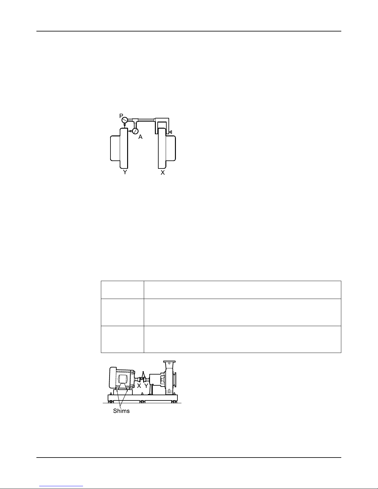
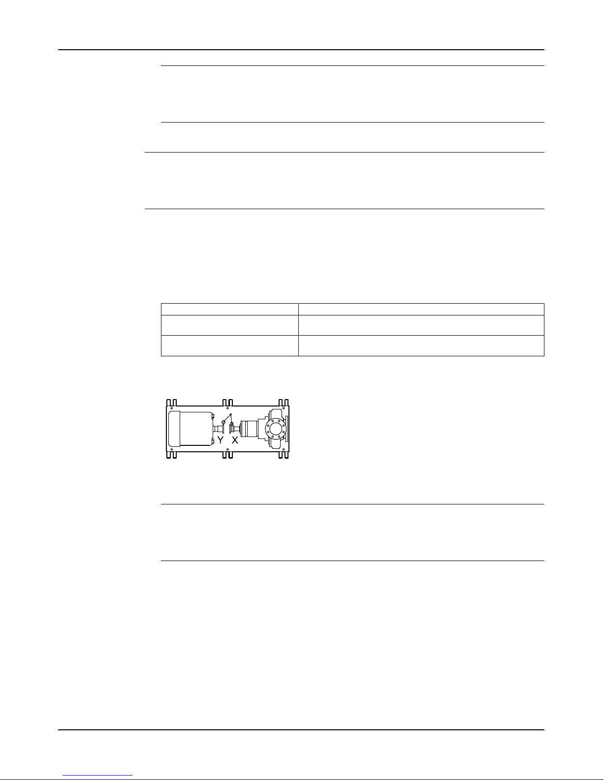
1. Attach two dial indicators on the pump coupling half (X):
a) Attach one indicator (P) so that the indicator rod comes into contact with the perimeter
of the driver coupling half (Y).
This indicator is used to measure parallel misalignment.
b) Attach the other indicator (A) so that the indicator rod comes into contact with the inner
end of the driver coupling half.
This indicator is used to measure angular misalignment.
Figure 22: Dial indicator attachment
2. Rotate the pump coupling half (X) in order to check that the indicators are in contact with
the driver coupling half (Y) but do not bottom out.
3. Adjust the indicators if necessary.
Pump-to-driver alignment instructions
Perform angular alignment for a vertical correction
1. Set the angular alignment indicator to zero at the top-center position (12 o’clock) of the
driver coupling half (Y).
2. Rotate the indicator to the bottom-center position (6 o’clock).
3. Record the indicator reading.
When the
reading value
is...
Then...
Negative The coupling halves are farther apart at the bottom than at the top. Perform one of
these steps:
• Add shims in order to raise the feet of the driver at the shaft end.
• Remove shims in order to lower the feet of the driver at the other end.
Positive Thecoupling halves are closer at the bottomthanatthetop.Performoneofthese
steps:
• Remove shims in order to lower the feet of the driver at the shaft end.
• Add shims in order to raise the feet of the driver at the other end.
Figure 23: Side view of an incorrect vertical alignment
4. Repeat the previous steps until the permitted reading value is achieved.
Page 37
Installation
Model 3196 i-FRAME Installation, Operation, and Maintenance Manual 35
Perform angular alignment for a horizontal correction
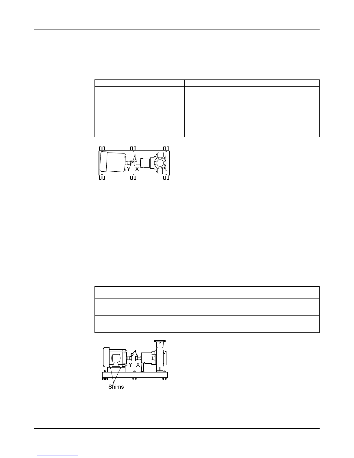
1. Set the angular alignment indicator (A) to zero on left side of the driver coupling half (Y),
90° from the top-center position (9 o’clock).
2. Rotate the indicator through the top-center position to the right side, 180° from the start
position (3 o’clock).
3. Record the indicator reading.
When the reading value is... Then...
Negative The coupling halves are farther apart on the right side than
the left. Perform one of these steps:
• Slide the shaft end of the driver to the left.
• Slide the opposite end to the right.
Positive Thecouplinghalvesareclosertogetherontherightside
than the left. Perform one of these steps:
• Slide the shaft end of the driver to the right.
• Slide the opposite end to the left.
Figure 24: Top view of an incorrect horizontal alignment
4. Repeat the previous steps until the permitted reading value is achieved.
Perform parallel alignment for a vertical correction
Refer to the alignment table in "Permitted indicator values for alignment checks" (see Table of
Contents for location of table) for the proper cold alignment value based on the motor
temperature rise and the pump operating temperature.
Before you start this procedure, make sure that the dial indicators are correctly set up.
A unit is in parallel alignment when the parallel indicator (P) does not vary by more than
0.05 mm | 0.002 in. as measured at four points 90° apart at the operating temperature.
1. Set the parallel alignment indicator (P) to zero at the top-center position (12 o’clock) of the
driver coupling half (Y).
2. Rotate the indicator to the bottom-center position (6 o’clock).
3. Record the indicator reading.
When the reading
value is...
Then...
Negative The pump coupling half (X) is lower than the driver coupling half (Y). Remove
shims of a thickness equal to half of the indicator reading value under each
driver foot.
Positive The pump coupling half (X) is higher than the driver coupling half (Y). Add
shims of a thickness equal to half of the indicator reading value to each driver
foot.
Figure 25: Side view of an incorrect vertical alignment
4. Repeat the previous steps until the permitted reading value is achieved.
Page 38
Installation
Model 3196 i-FRAME Installation, Operation, and Maintenance Manual36
NOTICE:
The specified permitted reading values are valid only at operating temperature. For cold
settings, other values are permitted. The correct tolerances must be used. Failure to do so
can result in misalignment.
Perform parallel alignment for a horizontal correction
NOTICE:
The specified permitted reading values are valid only at operating temperature. For cold
settings, other values are permitted. The correct tolerances must be used. Failure to do so can
result in misalignment.
A unit is in parallel alignment when the parallel indicator (P) does not vary by more than
0.05 mm | 0.002 in. as measured at four points 90° apart at the operating temperature.
1. Set the parallel alignment indicator (P) to zero on the left side of the driver coupling half (Y),
90° from the top-center position (9 o’clock).
2. Rotate the indicator through the top-center position to the right side, 180° from the start
position (3 o’clock).
3. Record the indicator reading.
When the reading value is... Then...
Negative The driver coupling half (Y) is to the left of the pump coupling
half (X).
Positive The driver coupling half (Y) is to the right of the pump coupling
half (X).
4. Slide the driver carefully in the appropriate direction. Make sure to slide the driver evenly.
Failure to do so can negatively affect horizontal angular correction.
Figure 26: Top view of an incorrect horizontal alignment
5. Repeat the previous steps until the permitted reading value is achieved.
NOTICE:
The specified permitted reading values are valid only at operating temperature. For cold
settings, other values are permitted. The correct tolerances must be used. Failure to do so
can result in misalignment.
Perform complete alignment for a vertical correction
A unit is in complete alignment when both the angular indicator (A) and the parallel indicator (P)
do not vary by more than 0.05 mm | 0.002 in. as measured at four points 90° apart.
1. Set the angular and parallel dial indicators to zero at the top-center position (12 o’clock) of
the driver coupling half (Y).
2. Rotate the indicators to the bottom-center position (6 o’clock).
3. Record the indicator readings.
4. Make corrections according to the separate instructions for angular and parallel alignment
until you obtain the permitted reading values.
Page 39
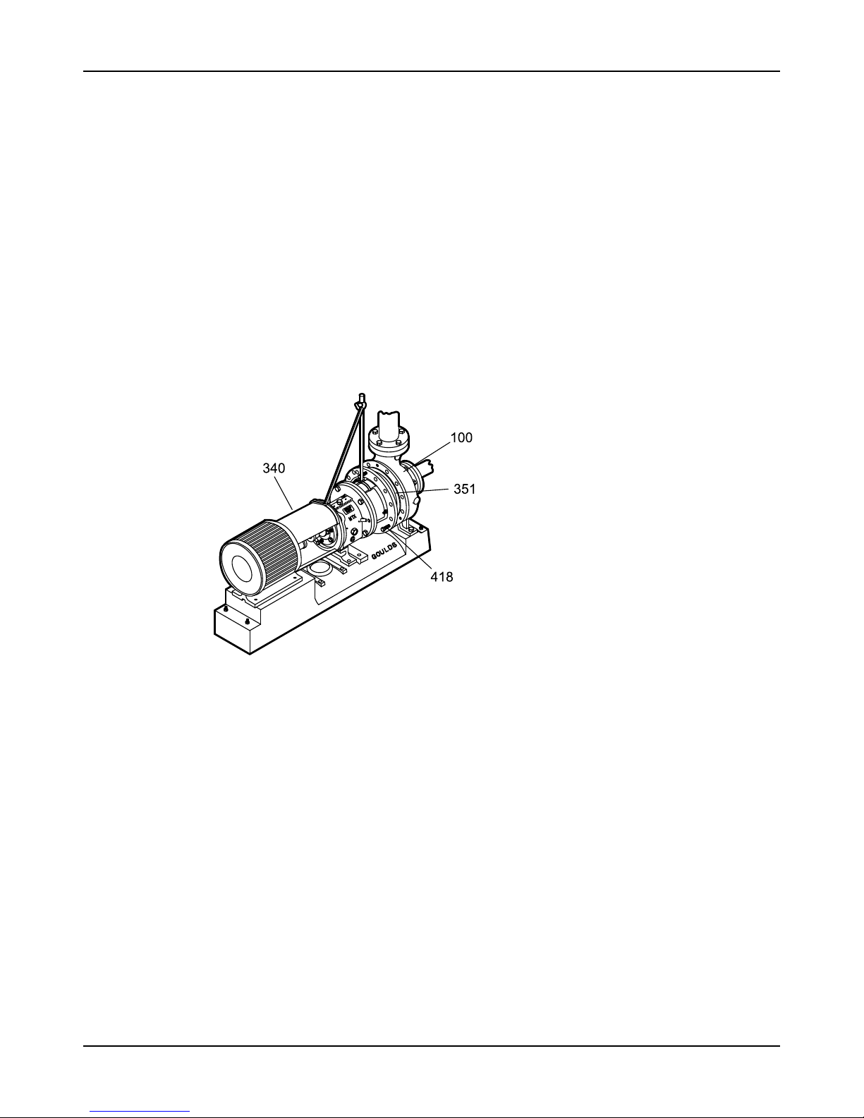
Installation
Model 3196 i-FRAME Installation, Operation, and Maintenance Manual 37
Perform complete alignment for a horizontal correction
A unit is in complete alignment when both the angular indicator (A) and the parallel indicator (P)
do not vary by more than 0.05 mm | 0.002 in. as measured at four points 90° apart.
1. Set the angular and parallel dial indicators to zero at the left side of the driver coupling half
(Y), 90° from the top-center position (9 o’clock).
2. Rotate the indicators through the top-center position to the right side, 180° from the start
position (3 o’clock).
3. Record the indicator readings.
4. Make corrections according to the separate instructions for angular and parallel alignment
until you obtain the permitted reading values.
C-face adapter
Intended use
The C-face adapter is a device that attaches the pump to the drive unit to minimize the axial
and radial play between the two coupling halves.
Illustration
Figure 27: Example of the C-face adapter (340)
Alignment requirements
When you use a C-face adapter, you do not have to align the shaft. The rabbeted fit of the drive
unit to the adapter and the adapter to the bearing housing automatically align the shafts to
within the specified limits.
Specified limits
A C-face adapter can attain a nominal alignment of 0.18mm | 0.007 in. Total Indicated Runout
(T.I.R.). However, because of the stack-up of the machining tolerances of the various parts, the
alignment can be as high as 0.38mm | 0.015 inches TIR. Use of a flexible coupling with an
elastomeric insert is required to maintain acceptable pump and motor life when using a c-face
adapter.
If high reliability (with shaft alignments of less than 0.05mm | 0.002 in.) is required for the pump,
use a foot-mounted drive unit on a precision-machined baseplate and perform a conventional
alignment.
Grout the baseplate
Required equipment:
Page 40
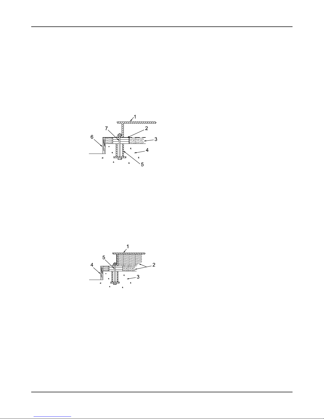
Installation
Model 3196 i-FRAME Installation, Operation, and Maintenance Manual38
• Cleaners: Do not use an oil-based cleaner because the grout will not bond to it. See the
instructions provided by the grout manufacturer.
• Grout: Non-shrink grout is recommended.
1. Clean all the areas of the baseplate that will come into contact with the grout.
2. Build a dam around the foundation.
3. Thoroughly wet the foundation that will come into contact with the grout.
4. Pour grout through the grout hole into the baseplate up to the level of the dam.
When you pour the grout, remove air bubbles from it by using one of these methods:
• Puddle with a vibrator.
• Pump the grout into place.
5. Allow the grout to set.
1. Baseplate
2. Shims or wedges
3. Grout
4. Foundation
5. Sleeve
6. Dam
7. Bolt
Figure 28: Pour grout into baseplate
6. Fill the remainder of the baseplate with grout, and allow the grout to set for at least 48
hours.
1. Baseplate
2. Grout
3. Foundation
4. Dam
5. Bolt
Figure 29: Fill remainder of baseplate with grout
7. Tighten the foundation bolts.
Page 41
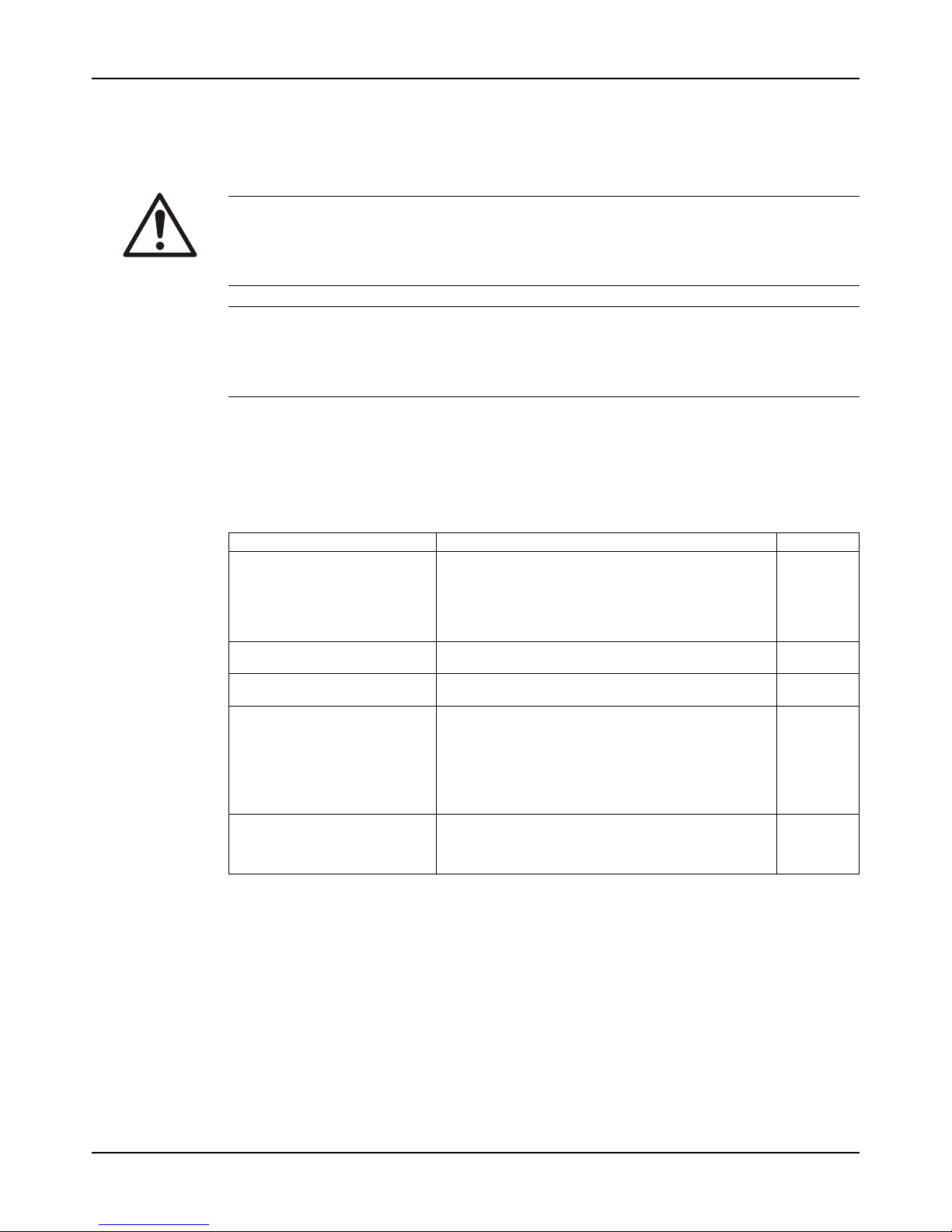
Installation
Model 3196 i-FRAME Installation, Operation, and Maintenance Manual 39
Piping checklists
General piping checklist
Precautions
WARNING:
Risk of premature failure. Casing deformation can result in misalignment and contact with
rotating parts, causing excess heat generation and sparks. Flange loads from the piping
system, including those from the thermal expansion of the piping, must not exceed the limits of
the pump.
NOTICE:
Vary the capacity with the regulating valve in the discharge line. Never throttle the flow from the
suction side. This action can result in decreased performance, unexpected heat generation,
and equipment damage.
Piping guidelines
Guidelines for piping are given in the Hydraulic Institute Standards available from the Hydraulic
Institute at 9 Sylvan Way, Parsippany, NJ 07054-3802. You must review this document before
you install the pump.
Checklist
Check Explanation/comment Checked
Check that all piping is supported
independently of, and lined up
naturally with, the pump flange.
This helps to prevent:
• Strain on the pump
• Misalignment between the pump and the drive unit
• Wear on the pump bearings and the coupling
• Wear on the pump bearings, seal, and shafting
Keep the piping as short as possible.
This helps to minimize friction losses.
Check that only necessary fittings
are used.
This helps to minimize friction losses.
Do not connect the piping to the
pump until:
• The grout for the baseplate
or sub-base becomes hard.
• The hold-down bolts for the
pump and the driver are
tightened.
—
If the pump handles liquids at
elevated temperatures, make
sure that the expansion loops and
joints are properly installed.
This helps to prevent misalignment due to linear expansion of the piping.
Page 42
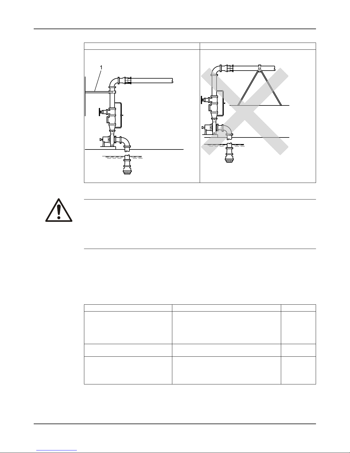
Installation
Model 3196 i-FRAME Installation, Operation, and Maintenance Manual40
Example: Installation for expansion
Correct Incorrect
This illustration shows a correct installation for
expansion:
1. Expansion loop/joint
This illustration shows an incorrect installation for
expansion:
Fastening
WARNING:
Risk of serious personal injury or property damage. Fasteners such as bolts and nuts are
critical to the safe and reliable operation of the product. Ensure appropriate use of fasteners
during installation or reassembly of the unit.
• Use fasteners of the proper size and material only.
• Replace all corroded fasteners.
• Ensure that all fasteners are properly tightened and that there are no missing fasteners.
Suction-piping checklist
Performance curve reference
Net positive suction head available (NPSHA) must always exceed NPSH required (NPSHR) as
shown on the published performance curve of the pump.
Suction-piping checks
Check Explanation/comment Checked
Check that the distance between the
inlet flange of the pump and the closest
elbow is at least two pipe diameters.
Check that the distance between the
inlet flange of the pump and the closest
elbow is at least five pipe diameters.
This minimizes the risk of cavitation in the
suction inlet of the pump due to turbulence.
See the Example sections for illustrations.
Check that elbows in general do not
have sharp bends.
See the Example sections for illustrations.
—
Check that the suction piping is one or
two sizes larger than the suction inlet of
the pump.
Install an eccentric reducer between
the pump inlet and the suction piping.
The suction piping must never have a smaller
diameter than the suction inlet of the pump.
See the Example sections for illustrations.
Page 43
Installation
Model 3196 i-FRAME Installation, Operation, and Maintenance Manual 41
Check Explanation/comment Checked
Check that the eccentric reducer at the
suction flange of the pump has the
following properties:
• Sloping side down
• Horizontal side at the top
See the example illustrations.
Suggested suction strainers are used.
Check that they are at least three times
the area of the suction piping.
Monitor the pressure drop across the
suction strainer.
An increased pressure drop across the
strainer of 5 psi (34.5 kPa) indicates
that the strainer should be removed
and cleaned.
After a period of time (24 hours minimum) system flushing should be complete and the suction strainer can be
removed.
Suction strainers help to prevent debris from
entering the pump.
Mesh holes with a minimum diameter of 1/16 in.
(1.6 mm) are recommended.
Liquids with specific gravity less than 0.60 a
pressure drop across the suction strainer may be
due to ice buildup. Ice buildup can cause turbulence, low pressure areas and pumpage vaporization.
If more than one pump operates from
the same liquid source, check that
separate suction-piping lines are used
for each pump.
This recommendation helps you to achieve a
higher pump performance and prevent vapor
locking especially with specific gravity of liquid
less than 0.60.
If necessary, make sure that the suction piping includes a drain valve and
that it is correctly installed.
—
Assure adequate insulation is applied
for liquids with specific gravity less than
0.60.
To assure sufficient NPSHa.
Liquid source below the pump
Check Explanation/comment Checked
Make sure that the suction piping is
free from air pockets.
This helps to prevent the occurrence of air and
cavitation in the pump inlet.
Check that the suction piping slopes
upwards from the liquid source to the
pump inlet.
—
If the pump is not self-priming, check
that a device for priming the pump is
installed.
Use a foot valve with a diameter that is at least
equivalent to the diameter of the suction piping.
Liquid source above the pump
Check Explanation/comment Checked
Check that an isolation valve is installed in the suction piping at a distance of at least two times the pipe
diameter from the suction inlet.
This permits you to close the line during pump
inspection and maintenance.
Do not use the isolation valve to throttle the pump.
Throttling can cause these problems:
• Loss of priming
• Excessive temperatures
• Damage to the pump
• Voiding the warranty
Make sure that the suction piping is
free from air pockets.
This helps to prevent the occurrence of air and
cavitation in the pump inlet.
Check that the piping is level or slopes
downward from the liquid source.
—
Make sure that no part of the suction
piping extends below the suction flange
of the pump.
—
Make sure that the suction piping is
adequately submerged below the surface of the liquid source.
This prevents air from entering the pump through
a suction vortex.
Page 44
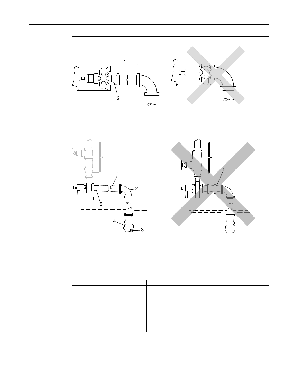
Installation
Model 3196 i-FRAME Installation, Operation, and Maintenance Manual42
Example: Elbow close to the pump suction inlet
Correct Incorrect
The correct distance between the inlet flange of the
pump and the closest elbow must be at least five
pipe diameters.
1. Enough distance to prevent cavitation
2. Eccentric reducer with a level top
Example: Suction piping equipment
Correct Incorrect
1. Suction pipe sloping upwards from liquid source
2. Long-radius elbow
3. Strainer
4. Foot valve
5. Eccentric reducer with a level top
1. Air pocket, because the eccentric reducer is not
used and because the suction piping does not
slope gradually upward from the liquid source
Discharge piping checklist
Checklist
Check Explanation/comment Checked
Check that an isolation valve is installed in the discharge line. For specific gravity less than 0.60, minimize distance from pump discharge.
The isolation valve is required for:
• Priming
• Regulation of flow
• Inspection and maintenance of the pump
• Reduce risk of pumpage vaporization and
vapor locking at low flow rates for low specific
gravity liquids.
See Example: Discharge piping equipment for
illustrations.
Page 45
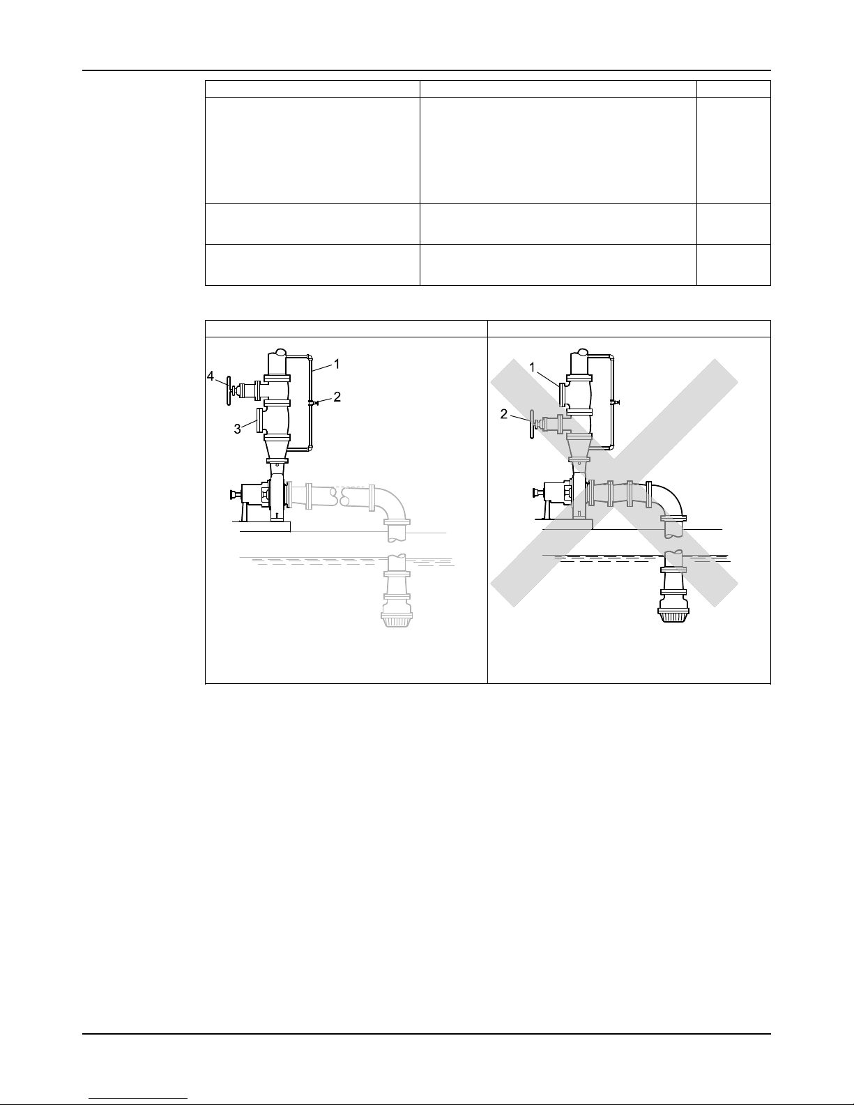
Installation
Model 3196 i-FRAME Installation, Operation, and Maintenance Manual 43
Check Explanation/comment Checked
Check that a check valve is installed in
the discharge line, between the isolation valve and the pump discharge
outlet.
The location between the isolation valve and the
pump allows inspection of the check valve.
The check valve prevents damage to the pump
and seal due to the back flow through the pump,
when the drive unit is shut off. It is also used to
restrain the liquid flow.
See Example: Discharge piping equipment for
illustrations.
If increasers are used, check that they
are installed between the pump and
the check valve.
See Example: Discharge piping equipment for
illustrations.
If quick-closing valves are installed in
the system, check that cushioning devices are used.
This protects the pump from surges and water
hammer.
Example: Discharge piping equipment
Correct Incorrect
1. Bypass line
2. Shut-off valve
3. Check valve
4. Discharge isolation valve
1. Check valve (incorrect position)
2. The isolation valve should not be positioned
between the check valve and the pump.
Page 46
Commissioning, Startup, Operation, and Shutdown
Model 3196 i-FRAME Installation, Operation, and Maintenance Manual44
Commissioning, Startup, Operation, and
Shutdown
Preparation for startup
WARNING:
• Breach of containment can cause fire, burns, and other serious injury. Failure to follow
these precautions before starting the unit may lead to dangerous operating conditions,
equipment failure, and breach of containment.
• Risk of serious physical injury or death. Exceeding any of the pump operating limits (e.g. pressure, temperature, power, etc.) could result in equipment failure, such as explosion,
seizure, or breach of containment. Assure that the system operating conditions are within
the capabilities of the pump.
• Risk of explosion and serious physical injury. Do not operate pump with blocked system
piping or with suction or discharge valves closed. This can result in rapid heating and
vaporization of pumpage.
• Risk of breach of containment and equipment damage. Ensure the pump operates only
between minimum and maximum rated flows. Operation outside of these limits can cause
high vibration, mechanical seal and/or shaft failure, and/or loss of prime.
• Running a pump without safety devices exposes operators to risk of serious personal
injury or death. Never operate a unit unless appropriate safety devices (guards, etc.) are
properly installed.
• Failure to disconnect and lock out driver power may result in serious physical injury or
death. Always disconnect and lock out power to the driver before performing any
installation or maintenance tasks.
• Electrical connections must be made by certified electricians in compliance with all
international, national, state, and local rules.
• Refer to driver/coupling/gear manufacturer's installation and operation manuals (IOM)
for specific instructions and recommendations.
• Starting the pump in reverse rotation can result in the contact of metal parts, heat
generation, and breach of containment. Ensure correct driver settings prior to starting any
pump.
• Risk of death or serious injury. Leaking fluid can cause fire and/or burns. Ensure all
openings are sealed prior to filling the pump.
Precautions
NOTICE:
• Excessive warm-up rates can cause equipment damage. Ensure the warm-up rate does
not exceed 1.4°C | 2.5°F per minute.
• When a cartridge mechanical seal is used, ensure that the set screws in the seal locking
ring are tightened and that the centering clips have been removed prior to startup. This
prevents seal or shaft sleeve damage by ensuring that the seal is properly installed and
centered on the sleeve.
You must follow these precautions before you start the pump:
• Flush and clean the system thoroughly to remove dirt or debris in the pipe system in order
to prevent premature failure at initial startup.
• Bring variable-speed drivers to the rated speed as quickly as possible.
• Run a new or rebuilt pump at a speed that provides enough flow to flush and cool the
close-running surfaces of the stuffing-box bushing.
Page 47
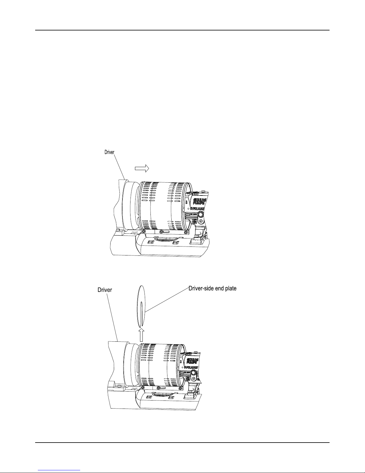
Commissioning, Startup, Operation, and Shutdown
Model 3196 i-FRAME Installation, Operation, and Maintenance Manual 45
• If temperatures of the pumped fluid will exceed 93°C | 200°F, then warm up the pump prior
to operation. Circulate a small amount of fluid through the pump until the casing
temperature is within 38°C | 100°F of the fluid temperature. Accomplish this by flowing fluid
from pump inlet to discharge drain (optionally, the casing vent can be included in warm-up
circuit but not required). Soak for (2) hours at process fluid temperature.
At initial startup, do not adjust the variable-speed drivers or check for speed governor or overspeed trip settings while the variable-speed driver is coupled to the pump. If the settings have
not been verified, then uncouple the unit and refer to instructions supplied by the driver
manufacturer.
Remove the coupling guard
1. Remove the nut, bolt, and washers from the slotted hole in the center of the coupling guard.
2. Slide the driver half of the coupling guard toward the pump.
3. Remove the nut, bolt, and washers from the driver half of the coupling guard.
4. Remove the driver-side end plate.
5. Remove the driver half of the coupling guard:
a) Slightly spread the bottom apart.
Page 48
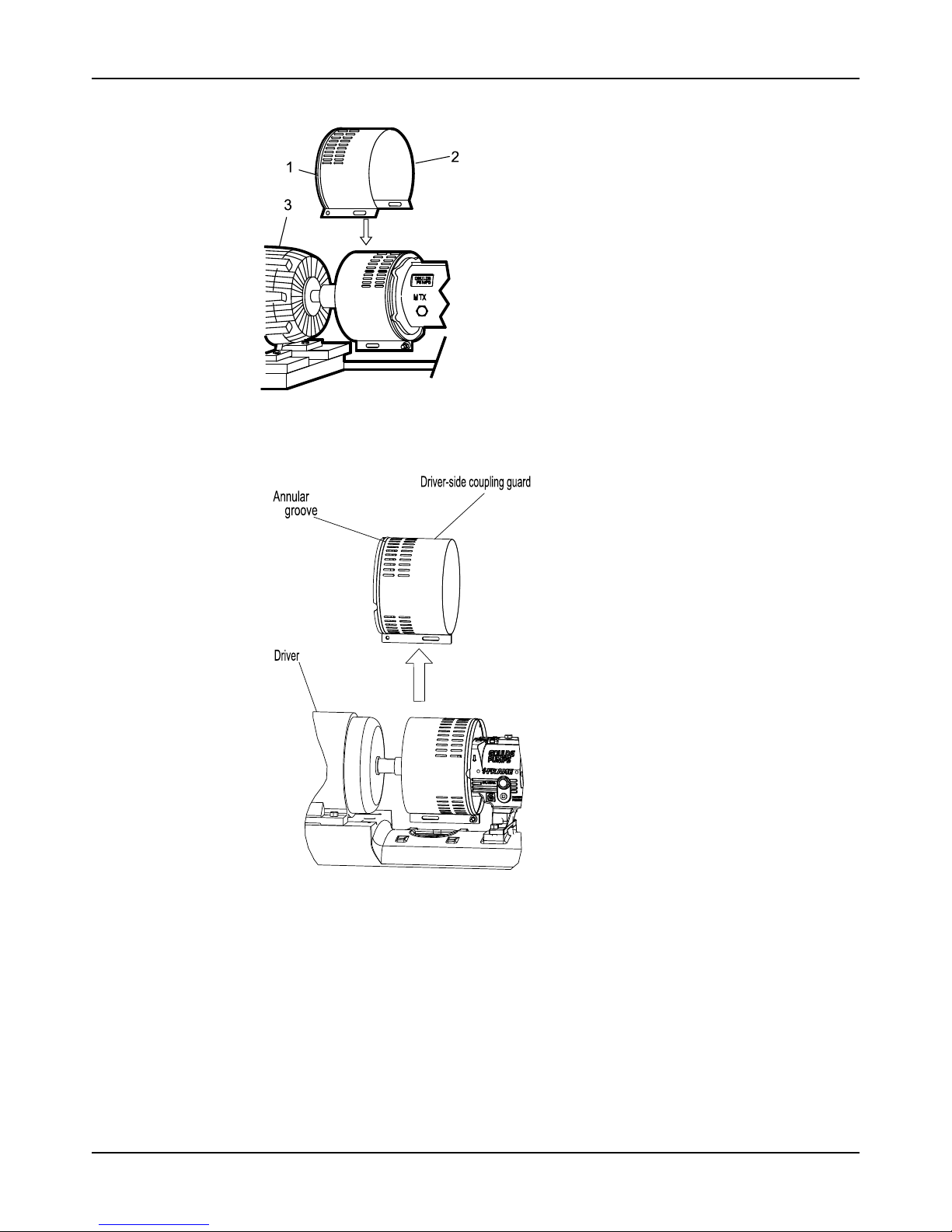
Commissioning, Startup, Operation, and Shutdown
Model 3196 i-FRAME Installation, Operation, and Maintenance Manual46
b) Lift upwards.
1. Annular groove
2. Driver half of the coupling guard
3. Driver
6. Remove the remaining nut, bolt, and washers from the pump half of the coupling guard.
It is not necessary to remove the end plate from the pump side of the bearing housing. You
can access the bearing-housing tap bolts without removing this end plate if maintenance of
internal pump parts is necessary.
7. Remove the pump half of the coupling guard:
a) Slightly spread the bottom apart.
Page 49
Commissioning, Startup, Operation, and Shutdown
Model 3196 i-FRAME Installation, Operation, and Maintenance Manual 47
b) Lift upwards.
1. Annular groove
2. Pump-side end plate
3. Driver
4. Pump half of the coupling guard
Check the rotation - Frame Mounted
WARNING:
• Starting the pump in reverse rotation can result in the contact of metal parts, heat
generation, and breach of containment. Ensure correct driver settings prior to starting any
pump.
• Failure to disconnect and lock out driver power may result in serious physical injury or
death. Always disconnect and lock out power to the driver before performing any
installation or maintenance tasks.
• Electrical connections must be made by certified electricians in compliance with all
international, national, state, and local rules.
• Refer to driver/coupling/gear manufacturer's installation and operation manuals (IOM)
for specific instructions and recommendations.
1. Lock out power to the driver.
2. Make sure that the coupling hubs are fastened securely to the shafts.
3. Make sure that the coupling spacer is removed.
The pump ships with the coupling spacer removed.
4. Unlock power to the driver.
5. Make sure that everyone is clear, and then jog the driver long enough to determine that the
direction of rotation corresponds to the arrow on the bearing housing or close-coupled
frame.
6. Lock out power to the driver.
Impeller-clearance check
The impeller-clearance check ensures the following:
• The pump turns freely.
• The pump operates at optimal efficiency for long equipment life and low energy
consumption.
Page 50
Commissioning, Startup, Operation, and Shutdown
Model 3196 i-FRAME Installation, Operation, and Maintenance Manual48
Impeller clearances (3196 and HT 3196)
NOTICE:
Set the cold (ambient) impeller clearance according to this table. Failure to do so may result in
heat generation and equipment damage. Higher clearances are used above 93°C | 200°F to
prevent the impeller from contacting the casing due to thermal expansion.
Table 8: Impeller clearances
This pump requires the impeller clearances in the following table.
Service temperature STi MTi/LTi XLT-i/i17
mm | in. mm | in. mm|in.
-29 to 93°C | -20 to 200°F 0.13 | 0.005 0.20 | 0.008 0.38 | 0.015
Up to 121°C | 250°F 0.15 | 0.006 0.22 | 0.009 0.41 | 0.016
Up to 149°C | 300°F 0.18 | 0.007 0.25 | 0.010 0.43 | 0.017
Up to 177°C| 350°F 0.22 | 0.009 0.30 | 0.012 0.48 | 0.019
Up to 204°C | 400°F 0.25 | 0.010 0.33 | 0.013 0.50 | 0.020
Up to 232°C | 450°F 0.28 | 0.011 0.35 | 0.014 0.53 | 0.021
Up to 260°C| 500°F 0.30 | 0.012 0.38 | 0.015 0.56 | 0.022
Up to 288°C | 550°F 0.33 | 0.013 0.41 | 0.016 0.58 | 0.023
Up to 316°C | 600°F 0.36 | 0.014 0.43 | 0.017 0.61 | 0.024
Up to 343°C | 650°F 0.40 | 0.016 0.48 | 0.019 0.66 | 0.026
Up to 371°C | 700°F 0.43 | 0.017 0.50 | 0.020 0.69 | 0.027
Impeller-clearance setting
Importance of a proper impeller clearance
A proper impeller clearance ensures that the pump runs at high performance.
WARNING:
• Risk of mechanical seal damage leading to breach of containment. If a cartridge
mechanical seal is used, ensure that the set screws in the seal locking ring are loosened
and that the centering clips have been installed prior to clearance adjustment.
Impeller clearance methods
You can set the impeller clearance with either of these methods:
• Dial indicator method
• Feeler gauge method
Set the impeller clearance - dial indicator method (all except CV 3196)
WARNING:
Failure to disconnect and lock out driver power may result in serious physical injury or death.
Always disconnect and lock out power to the driver before performing any installation or
maintenance tasks.
• Electrical connections must be made by certified electricians in compliance with all
international, national, state, and local rules.
• Refer to driver/coupling/gear manufacturer's installation and operation manuals (IOM) for
specific instructions and recommendations.
1. Remove the coupling guard.
Page 51
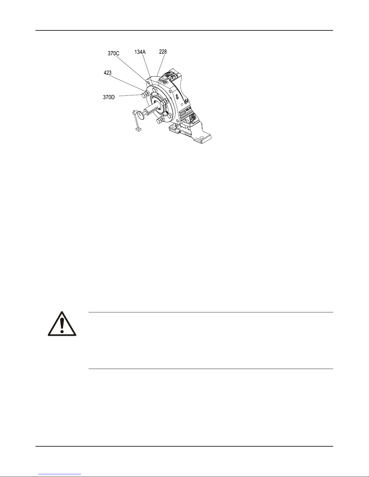
Commissioning, Startup, Operation, and Shutdown
Model 3196 i-FRAME Installation, Operation, and Maintenance Manual 49
2. Set the indicator so that the button contacts either the shaft end or the face of the coupling.
Figure 30: Dial indicator setting
3. Loosen the jam nuts (423) on the jack bolts (370D) , and then back the bolts out about two
turns.
4. Tighten the locking bolts evenly (370C), bringing the bearing housing (134A) towards the
frame (228) until the impeller contacts the casing.
5. Turn the shaft to ensure that there is contact between the impeller and the casing.
6. Set the indicator to zero and loosen the locking bolt (370C) about one turn.
7. Thread in the jack bolts (370D) until the jack bolts evenly contact the bearing frame.
8. Tighten the jack bolts evenly about one flat at a time, moving the bearing housing (134A)
away from the bearing frame until the indicator shows the correct clearance.
Refer to the impeller clearance table to determine the correct clearance.
9. Tighten the bolts evenly in this order:
a) Tighten the locking bolts (370C).
b) Tighten the jack bolts (370D).
Make sure to keep the indicator reading at the proper setting.
10. Make sure the shaft turns freely.
Set the impeller clearance - feeler gauge method (all except CV 3196)
WARNING:
Failure to disconnect and lock out driver power may result in serious physical injury or death.
Always disconnect and lock out power to the driver before performing any installation or
maintenance tasks.
• Electrical connections must be made by certified electricians in compliance with all
international, national, state, and local rules.
• Refer to driver/coupling/gear manufacturer's installation and operation manuals (IOM) for
specific instructions and recommendations.
1. Lock out the driver power and remove the coupling guard.
Page 52
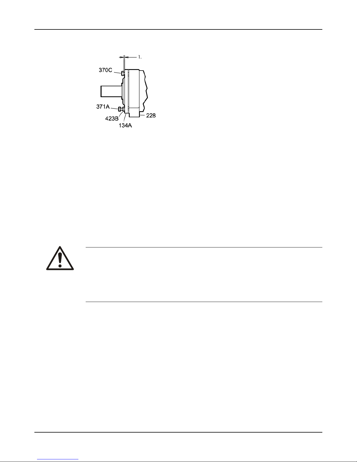
Commissioning, Startup, Operation, and Shutdown
Model 3196 i-FRAME Installation, Operation, and Maintenance Manual50
2. Loosen the jam nuts (423B) on the jack bolts (371A), and then back the bolts out about two
turns.
Figure 31: Loosen jam nuts
1. See impeller clearance table for distance
3. Evenly tighten the locking bolts (370C), bringing the bearing housing (134A) towards the
frame (228) until the impeller contacts the casing.
4. Turn the shaft to ensure that there is contact between the impeller and the casing.
5. Use a feeler gauge to set the gap between the three locking bolts (370C) and the bearing
housing (134A) to the correct impeller clearance.
Refer to the impeller clearance table to determine the correct clearance.
6. Use the three jack bolts (370D) to evenly loosen the bearing housing (134A) until it contacts
the locking bolts (370C).
7. Evenly tighten the jam nuts (423B).
8. Make sure the shaft turns freely.
Couple the pump and driver
WARNING:
Failure to disconnect and lock out driver power may result in serious physical injury or death.
Always disconnect and lock out power to the driver before performing any installation or
maintenance tasks.
• Electrical connections must be made by certified electricians in compliance with all
international, national, state, and local rules.
• Refer to driver/coupling/gear manufacturer's installation and operation manuals (IOM) for
specific instructions and recommendations.
Couplings must have proper certification to be used in an ATEX classified environment. Use
the instructions from the coupling manufacturer in order to lubricate and install the coupling.
Refer to driver/coupling/gear manufacturers IOM for specific instructions and recommendations.
Page 53
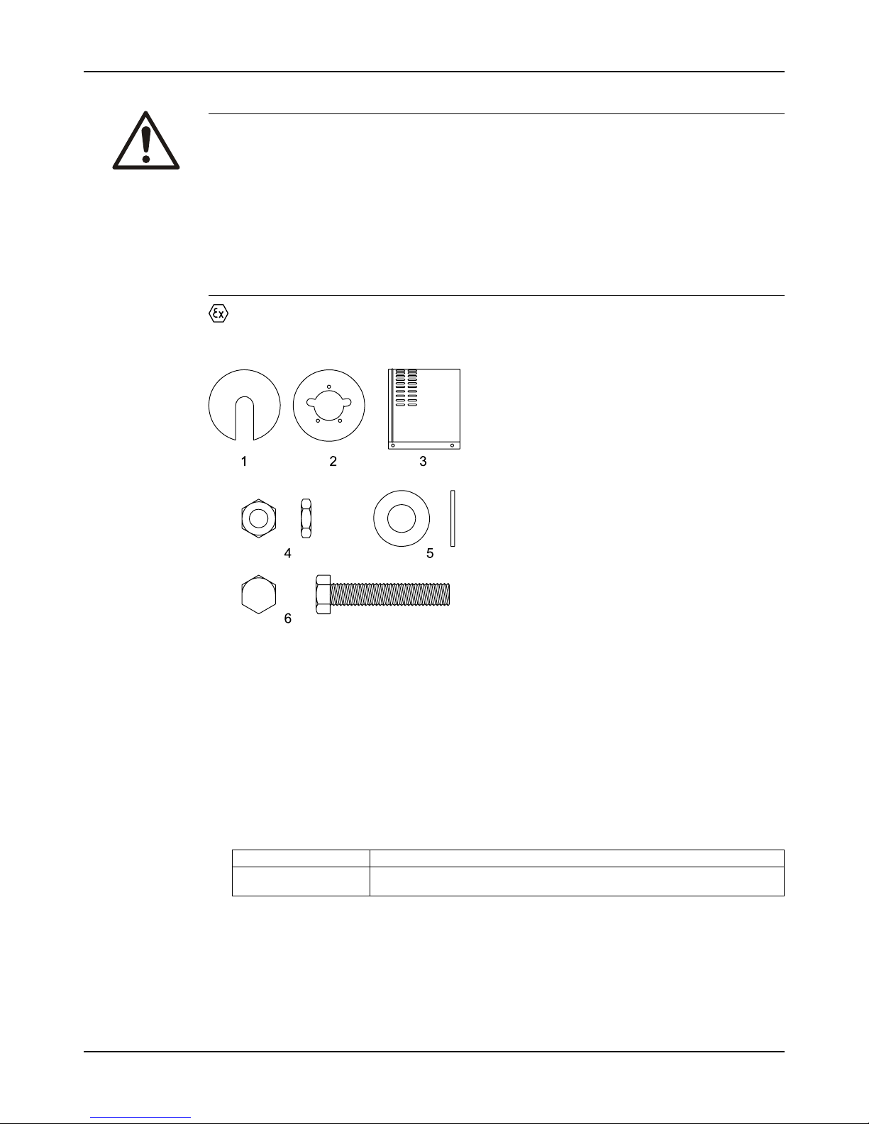
Commissioning, Startup, Operation, and Shutdown
Model 3196 i-FRAME Installation, Operation, and Maintenance Manual 51
Install the coupling guard
WARNING:
• Running a pump without safety devices exposes operators to risk of serious personal
injury or death. Never operate a unit unless appropriate safety devices (guards, etc.) are
properly installed.
• Failure to disconnect and lock out driver power may result in serious physical injury or
death. Always disconnect and lock out power to the driver before performing any
installation or maintenance tasks.
• Electrical connections must be made by certified electricians in compliance with all
international, national, state, and local rules.
• Refer to driver/coupling/gear manufacturer's installation and operation manuals (IOM)
for specific instructions and recommendations.
The coupling used in an Ex-classified environment must be properly certified and must be
constructed from a spark resistant material.
Required parts:
1. End plate, drive end
2. End plate, pump end
3. Guard half, 2 required
4. 3/8-16 nut, 3 required
5. 3/8 in. washer
6. 3/8-16 x 2 in. hex head bolt, 3 required
Figure 32: Required parts
1. De-energize the motor, place the motor in a locked-out position, and place a caution tag at
the starter that indicates the disconnect.
2. Put the pump-side end plate in place.
If the pump-side end plate is already in place, make any necessary coupling adjustments
and then proceed to the next step.
If the pump size is... Then...
STi, MTi, LTi Align the pump-side end plate to the bearing frame. You do not need to
adjust the impeller.
Page 54
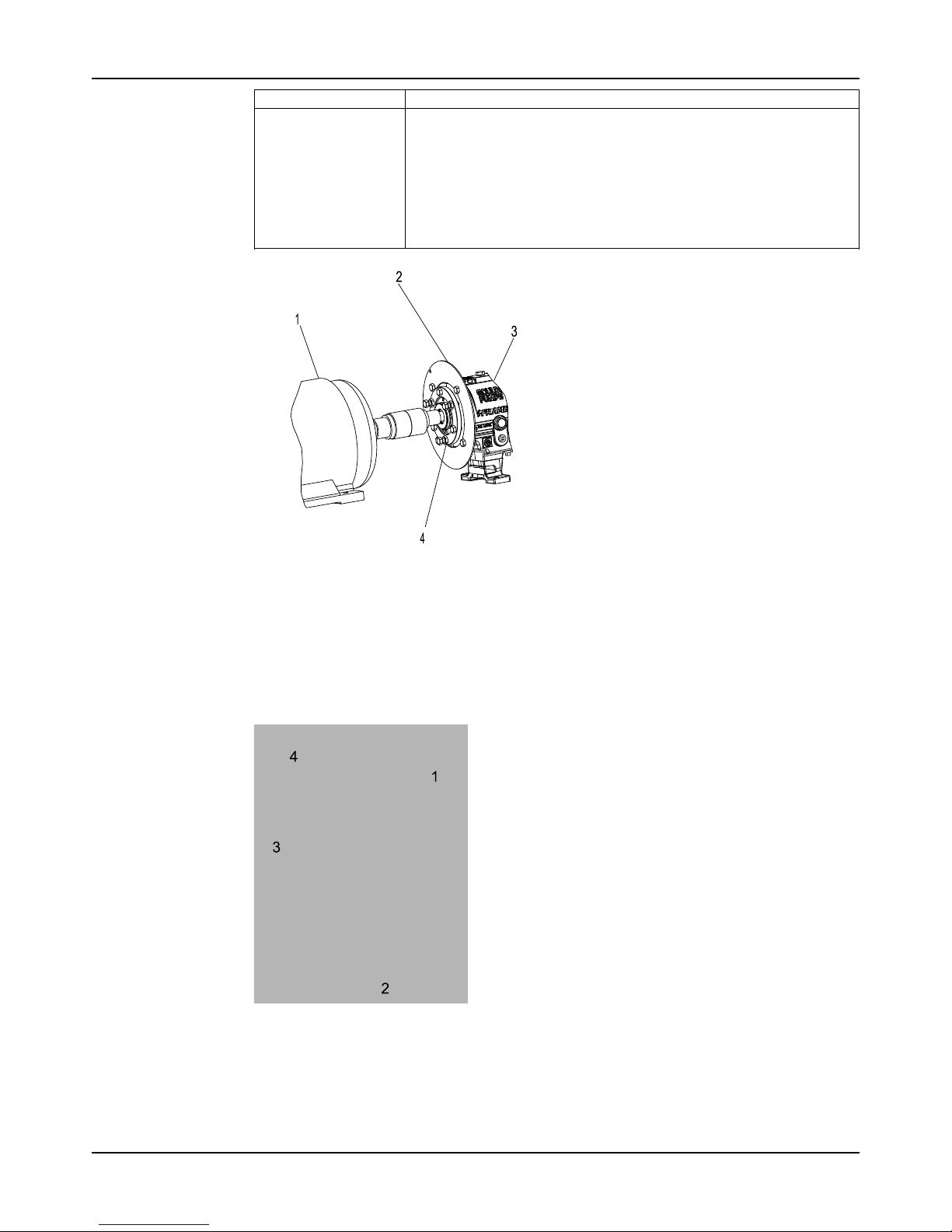
Commissioning, Startup, Operation, and Shutdown
Model 3196 i-FRAME Installation, Operation, and Maintenance Manual52
If the pump size is... Then...
XLT-i
1. Align the end plate on the pump side to the bearing housing so that you
meet these conditions:
1. The large slots on the end plate do not touch the bearing housing
tap bolts.
2. The small slots align with the impeller adjusting bolts.
2. Fasten the end plate to the bearing housing using the jam nuts on the
impeller adjusting bolts.
3. Check the impeller clearance. Refer to the impeller clearance table for
the correct impeller clearance.
1. Driver
2. Pump end plate
3. Bearing housing
4. Jam nut
Figure 33: Pump-side end plate placement
3. Put the pump-half of the coupling guard in place:
a) Slightly spread the bottom apart.
b) Place the coupling guard half over the pump-side end plate.
1. Annular groove
2. Pump-side end plate
3. Driver
4. Pump half of the coupling guard
Figure 34: Guard half installation
Page 55
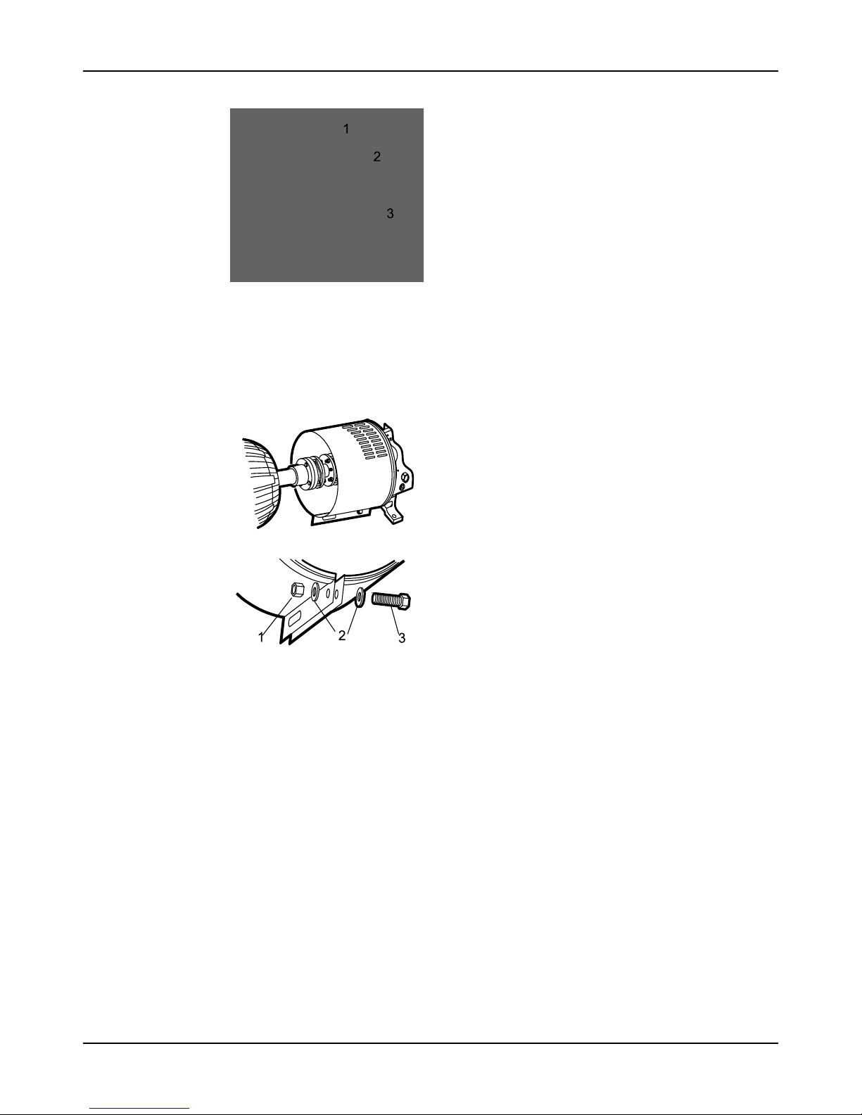
Commissioning, Startup, Operation, and Shutdown
Model 3196 i-FRAME Installation, Operation, and Maintenance Manual 53
The annular groove in the coupling guard half must fit around the end plate.
1. Annular groove
2. End plate (pump end)
3. Guard half
Figure 35: Annular groove in coupling guard
4. Use a bolt, a nut, and two washers to secure the coupling guard half to the end plate.
Tighten securely.
1. Nut
2. Washer
3. Bolt
Figure 36: Secure coupling guard half to end plate
5. Put the driver half of the coupling guard in place:
a) Slightly spread the bottom apart.
Page 56

Commissioning, Startup, Operation, and Shutdown
Model 3196 i-FRAME Installation, Operation, and Maintenance Manual54
b) Place the driver half of the coupling guard over the pump half of the coupling guard.
The annular groove in the coupling guard half must face the motor.
Figure 37: Placement of driver half of coupling guard
6. Place the driver-side end plate over the motor shaft.
Figure 38: Placement of driver half of coupling guard
7. Place the driver-side end plate in the annular groove of the driver-half of the coupling
guard.
8. Use a bolt, a nut, and two washers to secure the coupling guard half to the end plate. Handtighten only.
The hole is located on the driver-side of the coupling guard half.
Page 57
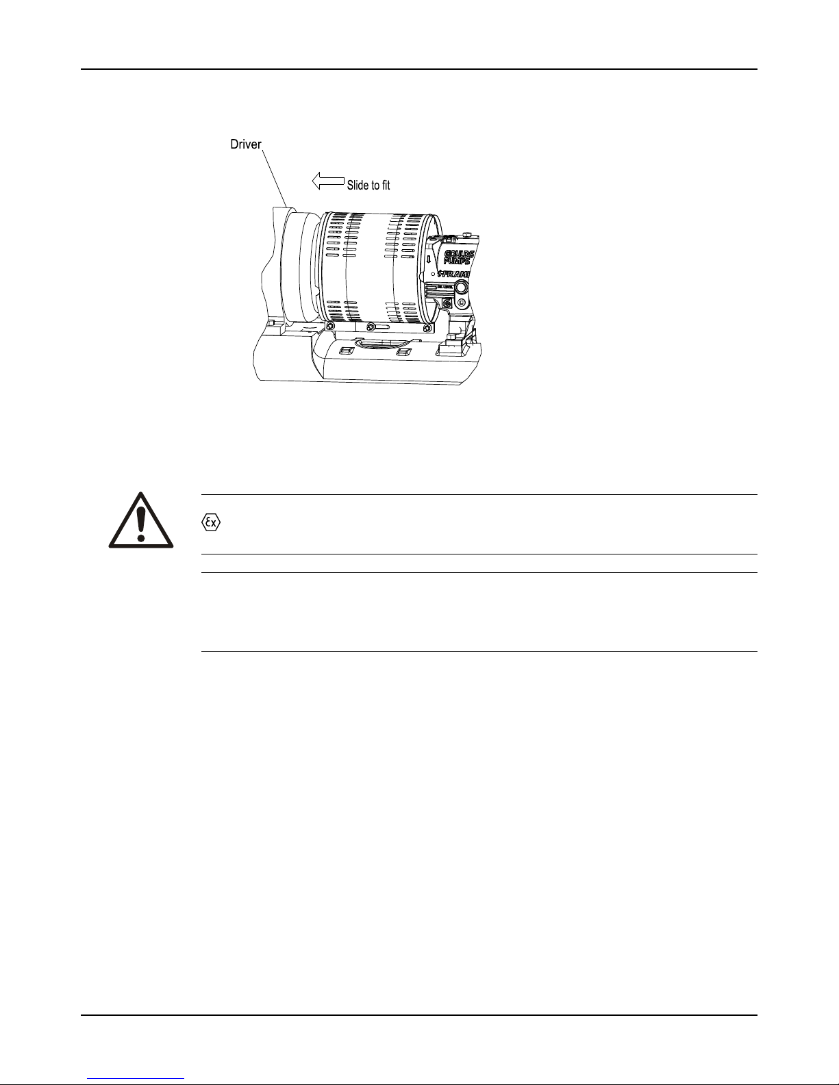
Commissioning, Startup, Operation, and Shutdown
Model 3196 i-FRAME Installation, Operation, and Maintenance Manual 55
9. Slide the driver-half of the coupling guard towards the motor so that the coupling guard
completely covers the shafts and coupling.
Figure 39: Slide driver-half of coupling guard towards motor
10. Use a nut, a bolt, and two washers to secure the coupling guard halves together.
11. Tighten all nuts on the guard assembly.
Bearing lubrication
WARNING:
Risk of explosive hazard and premature failure from sparks and heat generation. Ensure
bearings are properly lubricated prior to startup.
NOTICE:
Grease can settle in equipment left idle leaving bearings improperly lubricated. Check the
greasing on a pump that has been out of service for a long period of time and re-grease if
necessary.
Pumps are shipped without oil. You must lubricate oil-lubricated bearings at the job site.
Grease-lubricated bearings are lubricated at the factory.
The bearing manufacturer fills greased-for-life bearings with grease and seals them at the
factory. You do not need to lubricate or seal these bearings.
Page 58
Commissioning, Startup, Operation, and Shutdown
Model 3196 i-FRAME Installation, Operation, and Maintenance Manual56
Oil volumes
Oil volume requirements
This table shows the required amount of oil for oil-lubricated bearings.
Frame ml Qts. Oz.
STi 400 0.5 16
MTi 1400 1.5 47
LTi 1400 1.5 48
XLT-i and i17 3000 3 96
Lubricating-oil requirements
Oil requirements based on temperature
For the majority of operating conditions, bearing temperatures run between 49°C | 120°F and 82°C |
180°F, and you can use an oil of ISO viscosity grade 68 at 38°C | 100°F. If temperatures exceed 82°C |
180°F, refer to the table for temperature requirements.
Temperature Oil requirement
Bearing temperatures exceed 82°C | 180°F Use ISO viscosity grade 100 with bearing-frame
cooling or finned-tube oil cooler. The finned-tube oil
cooler is standard with the HT 3196 model and
optional for all other models.
Pumped-fluid temperatures exceed 177°C | 350°F Use synthetic lubrication.
Acceptable oil for lubricating bearings
Acceptable lubricants
Examples of acceptable high quality turbine oils with rust and oxidation inhibitors.
Brand Lubricant type
Chevron GST Oil 68
Exxon Teresstic EP 68
Mobil DTE 68 Heavy Medium
Phillips 66 Turbine Oil VG68
Shell Turbo T 68
Sunoco Sunvis 968
Royal Purple SYNFILM ISO VG 68 Synthetic Oil
Lubricate the bearings with oil
WARNING:
Risk of explosive hazard and premature failure from sparks and heat generation. Ensure
bearings are properly lubricated prior to startup.
Use a high-quality turbine oil with rust and oxidation inhibitors.
1. Remove the fill plug.
2. Fill the bearing frame with oil through the filler connection, which is located on top of the
bearing frame.
Fill the bearing frame with oil until the oil level reaches the middle of the sight glass (319).
The correct volume of oil required for each size of bearing frame can be found in the ‘Oil
Page 59
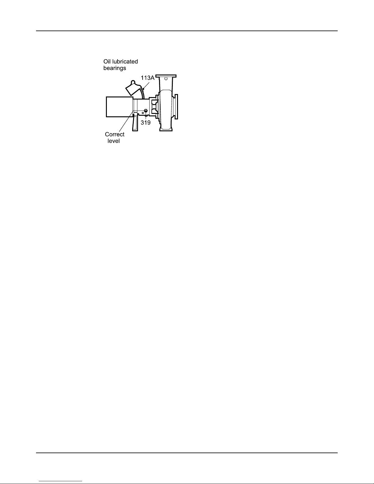
Commissioning, Startup, Operation, and Shutdown
Model 3196 i-FRAME Installation, Operation, and Maintenance Manual 57
Volume Requirements’ section in the ‘Bearing Maintenance’ / ‘Maintenance’ portion of the
IOM.
Figure 40: Oil filler connection
3. Replace the fill plug.
Lubricate the bearings with pure oil mist
Oil mist is an optional feature for this pump.
• To lubricate bearings with pure oil mist, follow the instructions provided by the
manufacturer of the oil-mist generator.
The inlet connections are on the top of the bearing frame.
Greased-for-life bearing lubrication
The bearing manufacturer fills greased-for-life bearings with grease and seals them at the
factory. You do not need to lubricate or seal these bearings. Refer to the Maintenance chapter
for re-greasing and maintenance procedures for these bearings.
Shaft-sealing options
In most cases, the manufacturer seals the shaft before shipping the pump. If your pump does
not have a sealed shaft, see the Shaft-seal maintenance section in the Maintenance chapter.
This model uses these types of shaft seals:
• Cartridge mechanical seal
• Conventional inside-component mechanical seal
• Conventional outside-component mechanical seal
• Dynamic seal
• Packed-stuffing-box option
Mechanical seal options
Pumps are usually shipped with mechanical seals installed. If they are not, then refer to the
mechanical seal manufacturer's installation instructions.
These are the mechanical seal options for this pump:
• Cartridge mechanical seal
• Conventional inside component mechanical seal
• Conventional outside component mechanical seal
Connection of sealing liquid for mechanical seals
Seal lubrication is required
Seal faces must have liquid film between them for proper lubrication. Locate the taps using the
illustrations shipped with the seal.
Page 60
Commissioning, Startup, Operation, and Shutdown
Model 3196 i-FRAME Installation, Operation, and Maintenance Manual58
Seal flushing methods
You can use these methods in order to flush or cool the seal:
Method Description
Product flush Run the piping so that the pump pushes the pumped fluid from the casing and
injects it into the seal gland. If necessary, an external heat exchanger cools the
pumped fluid before it enters the seal gland.
External flush Runthepipingsothatthepumpinjectsaclean,cool,compatibleliquiddirectlyinto
the seal gland. The pressure of the flushing liquid must be 0.35 to 1.01 kg/cm2| 5
to 15 psi greater than the seal chamber pressure. The injection rate must be 2 to 8
lpm | 0.5 to 2 gpm.
Other You can use other methods that employ multiple gland or seal chamber
connections. Refer to the mechanical seal reference drawing and piping diagrams.
Packed stuffing box option
WARNING:
Packed stuffing boxes are not allowed in an ATEX-classified environment.
The factory does not install the packing, lantern ring, or split gland.
These parts are included with the pump in the box of fittings. Before you start the pump, you
must install the packing, lantern ring, and split gland according to the Packed stuffing box
maintenance section in the Maintenance chapter.
Connection of sealing liquid for a packed stuffing box
NOTICE:
Make sure to lubricate the packing. Failure to do so may result in shortening the life of the
packing and the pump.
You must use an external sealing liquid under these conditions:
• The pumped fluid includes abrasive particles.
• The stuffing-box pressure is below atmospheric pressure when the pump is running with a
suction lift or when the suction source is in a vacuum. Under these conditions, packing is
not cooled and lubricated and air is drawn into pump.
Conditions for application of an external liquid
Condition Action
The stuffing box pressure is above atmospheric
pressure and the pumped fluid is clean.
Normal gland leaks of 40 to 60 drops per minute is
usually sufficient to lubricate and cool the packing.
You do not need sealing liquid.
The stuffing box pressure is below atmospheric
pressure or the pumped fluid is not clean.
An outside source of clean compatible liquid is
required.
An outside source of clean compatible liquid is
required.
You must connect the piping to the lantern ring
connection with a 40 to 60 drops-per-minute leak
rate. The pressure must be 1.01 kg/cm2| 15 psi
above the stuffing box pressure.
Dynamic-seal option
WARNING:
Dynamic seals are not allowed in an ATEX-classified environment.
The dynamic seal consists of two parts:
• Repeller seal
• Secondary seal (one of the following):
• Graphite packing
• Elastomenic face seal
Page 61
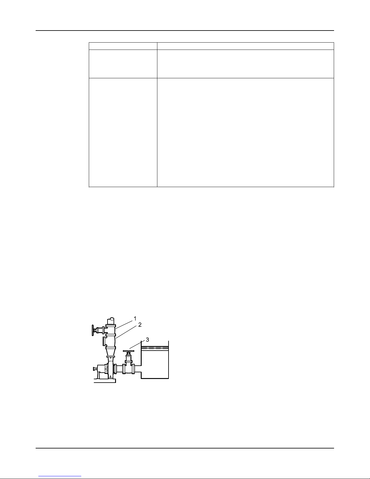
Commissioning, Startup, Operation, and Shutdown
Model 3196 i-FRAME Installation, Operation, and Maintenance Manual 59
Table 9: Dynamic seal part function
Part Function
Repeller seal A repeller seal prevents liquid from entering the stuffing box during
operation. The repeller normally does not require a flush. However, for
services that allow a build-up of solids on the repeller, you must install a
flush connection. If a danger of freezing exists, then you must install a drain
connection to drain the repeller chamber.
Secondary seal (graphite
packing)
This secondary seal prevents leaks during pump shutdown and is
comprised of the following:
• Graphite packing – Graphite packing provides adequate life running
dry but can provide longer performance if lubricated with clean water
or grease.
• If you lubricate with clean water, then the repeller reduces both the
quantity and pressure of seal water that is necessary. If the suction
head is less than the repeller capability, then the stuffing box
pressure is the same as the atmospheric pressure. Water pressure
for the seal must be high enough to overcome static head when the
pump is not operating to keep pumped fluid out of the packing.
There must be enough flow to cool the packing.
• If you lubricate with grease, then you must use spring-loaded
grease lubricators to maintain a constant supply.
• Elastomeric face seal – The elastomeric face seal consists of an
elastomer rotary fitted to the shaft and a ceramic stationary seat fitted
in the gland. To set an elastomeric face seal, refer to Set an
elastomeric face seal. This seal is designed to run dry, so no flush is
necessary.
Set an elastomeric face seal
This procedure ensures that the elastomeric seal attains proper contact. No other adjustments
are necessary.
1. Remove the gland nuts.
2. Slide the gland back on the sleeve.
3. Pull the rotary back on the sleeve until the rotary is about 25 mm | 1 in. beyond the stuffing
box face.
4. Push the gland back onto the studs, pushing the rotary back along the sleeve.
5. Tighten the gland nuts.
Prime the pump with the suction supply above the pump
1. Slowly open the suction isolation valve.
2. Open the air vents on the suction and discharge piping until the pumped fluid flows out.
3. Close the air vents.
1. Discharge isolation valve
2. Check valve
3. Suction isolation valve
Figure 41: Suction supply above pump
Page 62
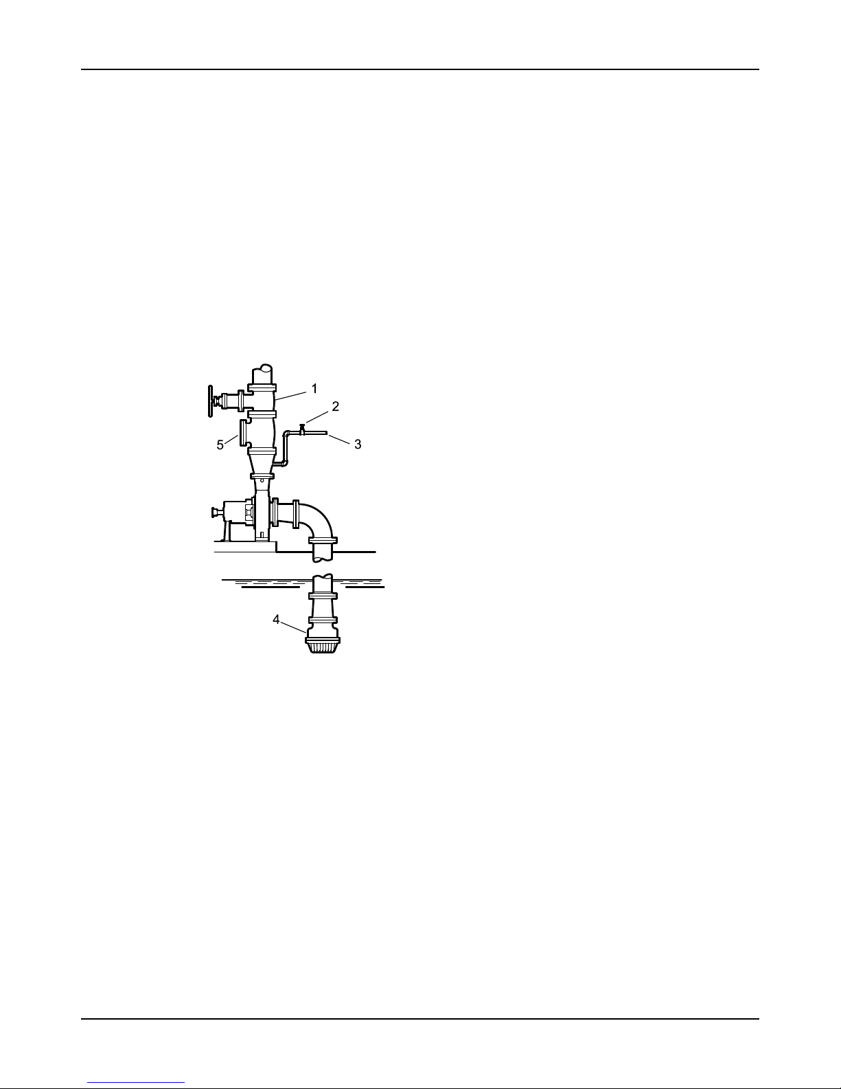
Commissioning, Startup, Operation, and Shutdown
Model 3196 i-FRAME Installation, Operation, and Maintenance Manual60
Prime the pump with the suction supply below the pump
Use a foot valve and an outside source of liquid in order to prime the pump. The liquid can
come from one of these sources:
• A priming pump
• A pressurized discharge line
• Another outside supply
1. Close the discharge isolation valve.
2. Open the air vent valves in the casing.
3. Open the valve in the outside supply line until only liquid escapes from the vent valves.
4. Close the vent valves.
5. Close the outside supply line.
This illustration is an example of priming the pump with a foot valve and an outside supply:
1. Discharge isolation valve
2. Shutoff valve
3. From outside supply
4. Foot valve
5. Check valve
Figure 42: Pump priming with suction supply below pump
This illustration is an example of priming the pump with a foot valve using a bypass around the
check valve:
Page 63
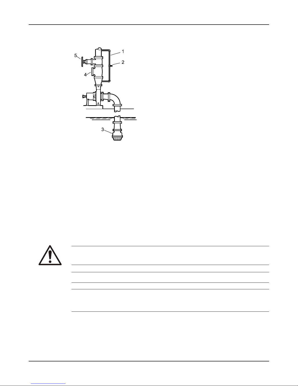
Commissioning, Startup, Operation, and Shutdown
Model 3196 i-FRAME Installation, Operation, and Maintenance Manual 61
1. By-pass line
2. Shutoff valve
3. Foot valve
4. Check valve
5. Discharge isolation valve
Figure 43: Pump priming with suction supply below pump with foot valve using bypass around
check valve
Other methods of priming the pump
You can also use these methods in order to prime the pump:
• Prime by ejector
• Prime by automatic priming pump
Start the pump
WARNING:
Risk of equipment damage, seal failure and breach of containment. Ensure all flush and cooling
systems are operating correctly prior to starting pump.
NOTICE:
NOTICE:
Risk of equipment damage on pure or purge-oil mist-lubricated units. Remove the viewing port
plugs to verify that oil mist is flowing properly. Reinstall the plugs after confirming.
Before you start the pump, you must perform these tasks:
• Open the suction valve.
• Open any recirculation or cooling lines.
1. Fully close or partially open the discharge valve, depending on system conditions.
2. Start the driver.
Page 64
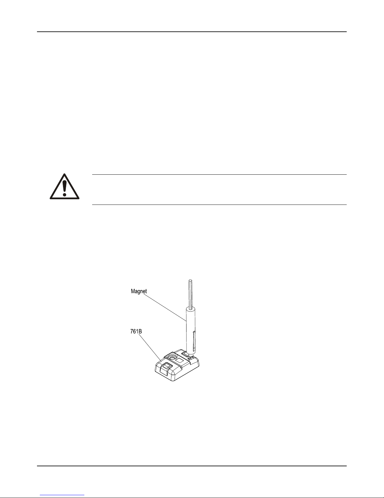
Commissioning, Startup, Operation, and Shutdown
Model 3196 i-FRAME Installation, Operation, and Maintenance Manual62
3. Slowly open the discharge valve until the pump reaches the desired flow.
4. Immediately check the pressure gauge to ensure that the pump quickly reaches the correct
discharge pressure.
5. If the pump fails to reach the correct pressure, perform these steps:
a) Stop the driver.
b) Prime the pump again.
c) Restart the driver.
6. Monitor the pump while it is operating:
a) Check the pump for bearing temperature, excessive vibration, and noise.
b) If the pump exceeds normal levels, then shut down the pump immediately and correct
the problem.
A pump can exceed normal levels for several reasons. See Troubleshooting for
information about possible solutions to this problem.
7. Repeat steps 5 and 6 until the pump runs properly.
Activate the i-ALERT®Condition Monitor
WARNING:
Explosive hazard and risk of personal injury. Heating to high temperatures could cause
combustion of the condition monitor. Never heat the condition monitor to temperatures in
excess of 149°C | 300°F or dispose of in a fire.
By using the i-ALERT®Condition monitor or the i-ALERT®2 Bluetooth Equipment Health
Monitor, you agree to be bound by the Terms and Conditions of the Software License
Agreement (page 18)
The condition monitor is ready for activation when the pump is running and has reached a
steady flow, pressure, and temperature. This process only takes a few minutes.
1. Place a small magnet on the condition monitor over the ITT logo and then remove it, as this
example shows.
Figure 44: i-ALERT®condition monitor
When the condition monitor is activated it:
1. Displays a series of red LEDs followed by a solid green LED.
2. Collects eight samples that are spaced one second apart.
3. Averages these readings to establish the baseline vibration level.
4. Flashes a green LED after approximately twelve seconds.
Page 65

Commissioning, Startup, Operation, and Shutdown
Model 3196 i-FRAME Installation, Operation, and Maintenance Manual 63
For the first ten minutes, the green LED flashes every second for five consecutive flashes
and then pauses to take a vibration reading. More frequent measurements (every six
seconds) are taken in this startup period so that an alarm can be immediately detected.
i-ALERT®Condition Monitor routine operation
To install and/or activate the i-ALERT®2 monitor, please refer to the i-ALERT®2 IOM orhttp://
www.ittproservices.com/aftermarket-products/monitoring/i-alert2/ (i-ALERT2.com). Routine op-
eration instructions are also included in the i-ALERT®2 IOM.
Measurement interval
This table shows the measurement intervals for the condition monitor during normal operation and when
the monitor is in alarm mode.
Mode Measurement interval
Normal operating mode Five minutes
Alarm mode Two minutes
When the condition monitor measures a reading beyond the specified temperature and
vibration limits, the appropriate red LED flashes. After the process or pump condition that
causes the alarm is corrected, the condition monitor returns to normal mode after one normallevel measurement.
Alarm mode
When the condition monitor is in alarm mode, you should investigate the cause of the condition
and make necessary corrections in a timely manner.
Magnetic device considerations
Be careful when you use magnetic devices in close proximity of the condition monitor, such as
magnetic vibration-monitoring probes or dial indicators. These magnetic devices can accidentally activate or deactivate the condition monitor resulting in improper alarm levels or loss of
monitoring.
Pump operation precautions
General considerations
NOTICE:
• Vary the capacity with the regulating valve in the discharge line. Never throttle the flow
from the suction side. This action can result in decreased performance, unexpected heat
generation, and equipment damage.
• Risk of equipment damage from unexpected heat generation. Do not overload the driver.
Ensure that the pump operating conditions are suitable for the driver. The driver can
overload in these circumstances:
• The specific gravity or viscosity of the fluid is greater than expected
• The pumped fluid exceeds the rated flow rate.
• Make sure to operate the pump at or near the rated conditions. Failure to do so can result
in pump damage from cavitation or recirculation.
Page 66
Commissioning, Startup, Operation, and Shutdown
Model 3196 i-FRAME Installation, Operation, and Maintenance Manual64
Operation at reduced capacity
WARNING:
• Risk of breach of containment and equipment damage. Excessive vibration levels can
cause damage to bearings, stuffing box, seal chamber, and/or mechanical seal. Observe
pump for vibration levels, bearing temperature, and excessive noise. If normal levels are
exceeded, shut down and resolve.
• Risk of explosion and serious physical injury. Do not operate pump with blocked system
piping or with suction or discharge valves closed. This can result in rapid heating and
vaporization of pumpage.
• Risk of equipment damage and serious physical injury. Heat build-up can cause rotating
parts to score or seize. Observe pump for excessive heat build-up. If normal levels are
exceeded, shut down and resolve.
NOTICE:
Cavitation can cause damage to the internal surfaces of the pump. Ensure net positive suction
head available (NPSHA) always exceeds NPSH required (NPSH3) as shown on the published
performance curve of the pump.
Operation under freezing conditions
NOTICE:
Do not expose an idle pump to freezing conditions. Drain all liquid that is inside the pump and
any auxiliary equipment. Failure to do so can cause liquid to freeze and damage the pump.
Shut down the pump
WARNING:
Precautions must be taken to prevent physical injury. The pump may handle hazardous and/or
toxic fluids. Proper personal protective equipment should be worn. Pumpage must be handled
and disposed of in conformance with applicable environmental regulations.
1. Slowly close the discharge valve.
2. Shut down and lock out the driver to prevent accidental rotation.
Deactivate the i-ALERT®Condition Monitor
NOTICE:
Always deactivate the condition monitor when the pump is going to be shut down for an
extended period of time. Failure to do so will result in reduced battery life.
1. Touch and hold a small magnet to the condition monitor over the ITT logo until the red
LEDs blink three times.
This should take 10-15 seconds if the condition monitor is in normal operating mode and
approximately five seconds if the condition monitor is in alarm mode.
2. Remove the magnet.
If the deactivation is successful, solid red LEDs will be displayed.
Page 67

Commissioning, Startup, Operation, and Shutdown
Model 3196 i-FRAME Installation, Operation, and Maintenance Manual 65
Reset the i-ALERT®Condition Monitor
To deactivate or reset the i-ALERT®2 monitor, please refer to the i-ALERT®2 IOM or iALERT2.com, http://www.ittproservices.com/aftermarket-products/monitoring/i-alert2/
Always reset the condition monitor when the pump is started after maintenance, system
change, or being shut down for an extended period of time. Failure to do so may result in false
baseline levels that could cause the condition monitor to alert in error.
1. Touch a magnet to the condition monitor over the ITT logo to turn the power on.The
condition monitor begins to establish a new baseline vibration level.
Page 68

Commissioning, Startup, Operation, and Shutdown
Model 3196 i-FRAME Installation, Operation, and Maintenance Manual66
Make the final alignment of the pump and driver
WARNING:
• Failure to disconnect and lock out driver power may result in serious physical injury or
death. Always disconnect and lock out power to the driver before performing any
installation or maintenance tasks.
• Electrical connections must be made by certified electricians in compliance with all
international, national, state, and local rules.
• Refer to driver/coupling/gear manufacturer's installation and operation manuals (IOM)
for specific instructions and recommendations.
• Misalignment can cause decreased performance, equipment damage, and even catastrophic failure of frame-mounted units leading to serious injury. Proper alignment is the
responsibility of the installer and the user of the unit. Check the alignment of all drive
components prior to operating the unit.
• Follow the coupling installation and operation procedures from the coupling manufactur-
er.
You must check the final alignment after the pump and driver are at operating temperature. For
initial alignment instructions, see the Installation chapter.
1. Run the unit under actual operating conditions for enough time to bring the pump, driver,
and associated system to operating temperature.
2. Shut down the pump and the driver.
3. Remove the coupling guard.
See Remove the coupling guard in the Maintenance chapter.
4. Check the alignment while the unit is still hot.
See Pump-to-driver alignment in the Installation chapter.
5. Reinstall the coupling guard.
6. Restart the pump and driver.
Page 69

Maintenance
Model 3196 i-FRAME Installation, Operation, and Maintenance Manual 67
Maintenance
Maintenance schedule
Maintenance inspections
A maintenance schedule includes these types of inspections:
• Routine maintenance
• Routine inspections
• Three-month inspections
• Annual inspections
Shorten the inspection intervals appropriately if the pumped fluid is abrasive or corrosive or if
the environment is classified as potentially explosive.
Routine maintenance
Perform these tasks whenever you perform routine maintenance:
• Lubricate the bearings.
• Inspect the seal.
Routine inspections
Perform these tasks whenever you check the pump during routine inspections:
• Check the level and condition of the oil through the sight glass on the bearing frame.
• Check for unusual noise, vibration, and bearing temperatures.
• Check the pump and piping for leaks.
• Analyze the vibration.
• Inspect the discharge pressure.
• Inspect the temperature.
• Check the seal chamber and stuffing box for leaks.
• Ensure that there are no leaks from the mechanical seal.
• Adjust or replace the packing in the stuffing box if you notice excessive leaking.
Three-month inspections
Perform these tasks every three months:
• Check that the foundation and the hold-down bolts are tight.
• Check the packing if the pump has been left idle, and replace as required.
• Change the oil every three months (2000 operating hours) at minimum.
• Change the oil more often if there are adverse atmospheric or other conditions that
might contaminate or break down the oil.
• Check the shaft alignment, and realign as required.
Annual inspections
Perform these inspections one time each year:
• Check the pump capacity.
• Check the pump pressure.
• Check the pump power.
If the pump performance does not satisfy your process requirements, and the process
requirements have not changed, then perform these steps:
1. Disassemble the pump.
2. Inspect it.
Page 70
Maintenance
Model 3196 i-FRAME Installation, Operation, and Maintenance Manual68
3. Replace worn parts.
Bearing maintenance
These bearing lubrication sections list different temperatures of the pumped fluid. If the
pump is ATEX-certified and the temperature of the pumped fluid exceeds the permitted
temperature values, then consult your ITT representative.
Bearing lubrication schedule
Type of bearing First lubrication Lubrication intervals
Oil-lubricated bearings Add oil before you install and start
the pump. Change the oil after
200 hours for new bearings.
After the first 200 hours, change
the oil every 2000 operating hours
or every three months.
Grease-lubricated bearings Grease-lubricated bearings are in-
itially lubricated at the factory.
Regrease bearings every 2000
operating hours or every three
months.
Lubricating-oil requirements
Oil requirements based on temperature
For the majority of operating conditions, bearing temperatures run between 49°C | 120°F and 82°C |
180°F, and you can use an oil of ISO viscosity grade 68 at 38°C | 100°F. If temperatures exceed 82°C |
180°F, refer to the table for temperature requirements.
Temperature Oil requirement
Bearing temperatures exceed 82°C | 180°F Use ISO viscosity grade 100 with bearing-frame
cooling or finned-tube oil cooler. The finned-tube oil
cooler is standard with the HT 3196 model and
optional for all other models.
Pumped-fluid temperatures exceed 177°C | 350°F Use synthetic lubrication.
Page 71
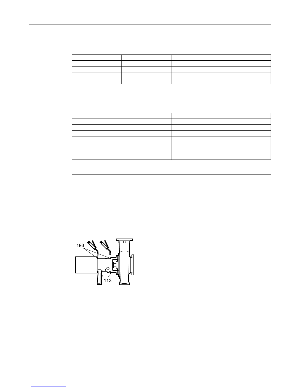
Maintenance
Model 3196 i-FRAME Installation, Operation, and Maintenance Manual 69
Oil volumes
Oil volume requirements
This table shows the required amount of oil for oil-lubricated bearings.
Frame ml Qts. Oz.
STi 400 0.5 16
MTi 1400 1.5 47
LTi 1400 1.5 48
XLT-i and i17 3000 3 96
Acceptable oil for lubricating bearings
Acceptable lubricants
Examples of acceptable high quality turbine oils with rust and oxidation inhibitors.
Brand Lubricant type
Chevron GST Oil 68
Exxon Teresstic EP 68
Mobil DTE 68 Heavy Medium
Phillips 66 Turbine Oil VG68
Shell Turbo T 68
Sunoco Sunvis 968
Royal Purple SYNFILM ISO VG 68 Synthetic Oil
Regrease the grease-lubricated bearings
NOTICE:
Risk of equipment damage. Ensure that the grease container, the greasing device, and the
fittings are clean. Failure to do so can result in impurities entering the bearing housing while
regreasing the bearings.
Figure 45: Bearing lubrication
1. Wipe dirt from the grease fittings.
2. Remove the two grease-relief plugs from the bottom of the frame.
3. Fill both of the grease cavities through the fittings with a recommended grease until the
fresh grease comes out of the relief holes.
4. Make sure that the frame seals are seated in the bearing housing.
If they are not, press them in place with the drains located at the bottom.
5. Reinstall the grease-relief plugs.
6. Wipe off any excess grease.
7. Recheck the alignment.
Page 72
Maintenance
Model 3196 i-FRAME Installation, Operation, and Maintenance Manual70
The bearing temperature usually rises after you regrease due to an excess supply of grease.
Temperatures return to normal in about two to four operating hours as the pump runs and
purges the excess grease from the bearings.
Lubricating-grease requirements
Precautions
NOTICE:
• Avoid equipment damage or decreased performance. Never mix greases of different
consistencies (NLGI 1 or 3 with NLGI 2) or with different thickeners. For example, never
mix a lithium-based grease with a polyurea based grease. If it is necessary to change the
grease type or consistency, remove the rotor and old grease from the housing before
regreasing.
Bearing temperature
Bearing temperatures are generally about 18°C | 20°F greater than bearing-housing outer surface
temperatures.
This table shows the type of grease required for the operating temperature of the pump.
Bearing temperature Type of grease
-15°C to 110°C | 5°F to 230°F Use a lithium-based mineral-oil grease with a consistency of NLGI 2.
Exceed 177°C | 350°F Useahigh-temperaturegrease.Mineral-oilgreases
should have oxidation stabilizers and a consistency
of NGLI 3.
Grease recommendations based on temperature
Most pumps use Sunoco 2EP grease. High temperature units that can pump fluids with a temperature
greater than 177°C | 350°F use Mobil SCH32.
This table shows which brand of grease to use when lubricating the pump.
Brand When temperature of pumped
fluid is less than 177°C | 350°F
NLGI consistency 2
When temperature of pumped
fluid is greater than177°C |
350°F NLGI consistency 3
Mobil Mobilux EP2 SCH32
Exxon Unirex N2 Unirex N3
Sunoco Mutipurpose 2EP N/A
SKF LGMT 2 LGMT 3
Lubricate the bearings after a shutdown period
1. Flush out the bearings and bearing frame with a light oil to remove contaminants.
During flushing, make sure to rotate the shaft slowly by hand.
2. Flush the bearing housing with the proper lubricating oil to ensure oil quality after cleaning.
3. Refer to "Reassembly" section for proper bearing greasing procedure.
Mechanical-seal maintenance
WARNING:
The mechanical seal used in an Ex-classified environment must be properly certified.
CAUTION:
Running a mechanical seal dry, even for a few seconds, can cause seal failure and physical
injury. Never operate the pump without liquid supplied to the mechanical seal.
Page 73
Maintenance
Model 3196 i-FRAME Installation, Operation, and Maintenance Manual 71
Cartridge-type mechanical seals
Cartridge-type mechanical seals are commonly used. Cartridge seals are preset by the seal
manufacturer and require no field settings. Cartridge seals installed by the user require
disengagement of the holding clips prior to operation, allowing the seal to slide into place. If the
seal has been installed in the pump by ITT, these clips have already been disengaged.
Other mechanical seal types
For other types of mechanical seals, refer to the instructions provided by the seal manufacturer
for installation and setting.
Reference drawing
The manufacturer supplies a reference drawing with the data package. Keep this drawing for
future use when you perform maintenance and seal adjustments. The seal drawing specifies
the required flush fluid and attachment points.
Before you start the pump
Check the seal and all flush piping.
Mechanical seal life
The life of a mechanical seal depends on the cleanliness of the pumped fluid. Due to the
diversity of operating conditions, it is not possible to give definite indications as to the life of a
mechanical seal.
Packed stuffing-box maintenance
WARNING:
• Packed stuffing boxes are not allowed in an ATEX-classified environment.
• Failure to disconnect and lock out driver power may result in serious physical injury. Never
attempt to replace the packing until the driver is properly locked out.
Accepted leakage rate
It is not necessary to shut down or disassemble the pump to inspect the packing operation.
During normal operation, the packing should leak approximately one drop per second.
Adjustment of gland
Adjust the gland if the leakage rate is greater than or less than the specified rate.
Evenly adjust each of the two gland bolts with a one-quarter (1/4) turn until the desired leakage
rate is obtained. Tighten the bolts to decrease the rate. Loosen the bolts to increase the rate.
Tightening of packing
NOTICE: Never over-tighten packing to the point where less than one drop per second is
observed. Over-tightening can cause excessive wear and power consumption during operation.
If you cannot tighten the packing to obtain less than the specified leakage rate, then replace the
packing.
Page 74
Maintenance
Model 3196 i-FRAME Installation, Operation, and Maintenance Manual72
Dynamic-seal maintenance
WARNING:
Dynamic seals are not allowed in an ATEX-classified environment.
About the dynamic seal
Dynamic seal parts do not wear substantially to affect operation and do not require
maintenance unless the service is particularly abrasive or corrosive.
Repeller
The dynamic repeller prevents pumpage leaks through the stuffing box when the pump
operates under published acceptable conditions.
Static seal
A static seal prevents leakage when the pump is shut down. A static seal is either of the
following:
• a lip seal
• an elastomeric-face seal
• graphite packing
The only maintenance that the lip seal and the elastomeric-face seal require is replacement
when leakage becomes excessive.
The graphite packing should be installed as stuffing-box packing and is designed to run dry.
Disassembly precautions
WARNING:
• Risk of serious physical injury or death from rapid depressurization. Ensure pump is
isolated from system and pressure is relieved before disassembling pump, removing
plugs, opening vent or drain valves, or disconnecting piping.
• Risk of serious personal injury. Applying heat to impellers, propellers, or their retaining
devices can cause trapped liquid to rapidly expand and result in a violent explosion. This
manual clearly identifies accepted methods for disassembling units. These methods must
be adhered to. Never apply heat to aid in their removal unless explicitly stated in this
manual.
• Failure to disconnect and lock out driver power may result in serious physical injury or
death. Always disconnect and lock out power to the driver before performing any
installation or maintenance tasks.
• Electrical connections must be made by certified electricians in compliance with all
international, national, state, and local rules.
• Refer to driver/coupling/gear manufacturer's installation and operation manuals (IOM)
for specific instructions and recommendations.
• Handling heavy equipment poses a crush hazard. Use caution during handling and wear
appropriate Personal Protective Equipment (PPE, such as steel-toed shoes, gloves, etc.)
at all times.
• Precautions must be taken to prevent physical injury. The pump may handle hazardous
and/or toxic fluids. Proper personal protective equipment should be worn. Pumpage must
be handled and disposed of in conformance with applicable environmental regulations.
• Risk of serious personal injury from exposure to hazardous or toxic liquids. A small amount
of liquid will be present in certain areas like the seal chamber upon disassembly.
Page 75
Maintenance
Model 3196 i-FRAME Installation, Operation, and Maintenance Manual 73
CAUTION:
• Avoid injury. Worn pump components can have sharp edges. Wear appropriate gloves
while handling these parts.
Tools required
In order to disassemble the pump, you need these tools:
• Bearing puller
• Brass drift punch
• Cleaning agents and solvents
• Dial indicators
• Feeler gauges
• Hex wrenches
• Hydraulic press
• Induction heater
• Leveling blocks and shims
• Lifting sling
• Micrometer
• Rubber mallet
• Screwdriver
• Snap-ring pliers
• Torque wrench with sockets
• Wrenches
• Lifting eyebolt (dependent on pump size)
Drain the pump
CAUTION:
• Risk of physical injury. Allow all system and pump components to cool before handling.
1. Leave the drain valve open and remove the drain plug located on the bottom of the pump
housing.
Do not reinstall the plug or close the drain valve until the reassembly is complete.
2. Remove the coupling guard.
Remove the coupling
1. Disconnect the coupling.
2. Remove the C-face adapter.
3. Remove the coupling-guard pump end-plate.
Page 76
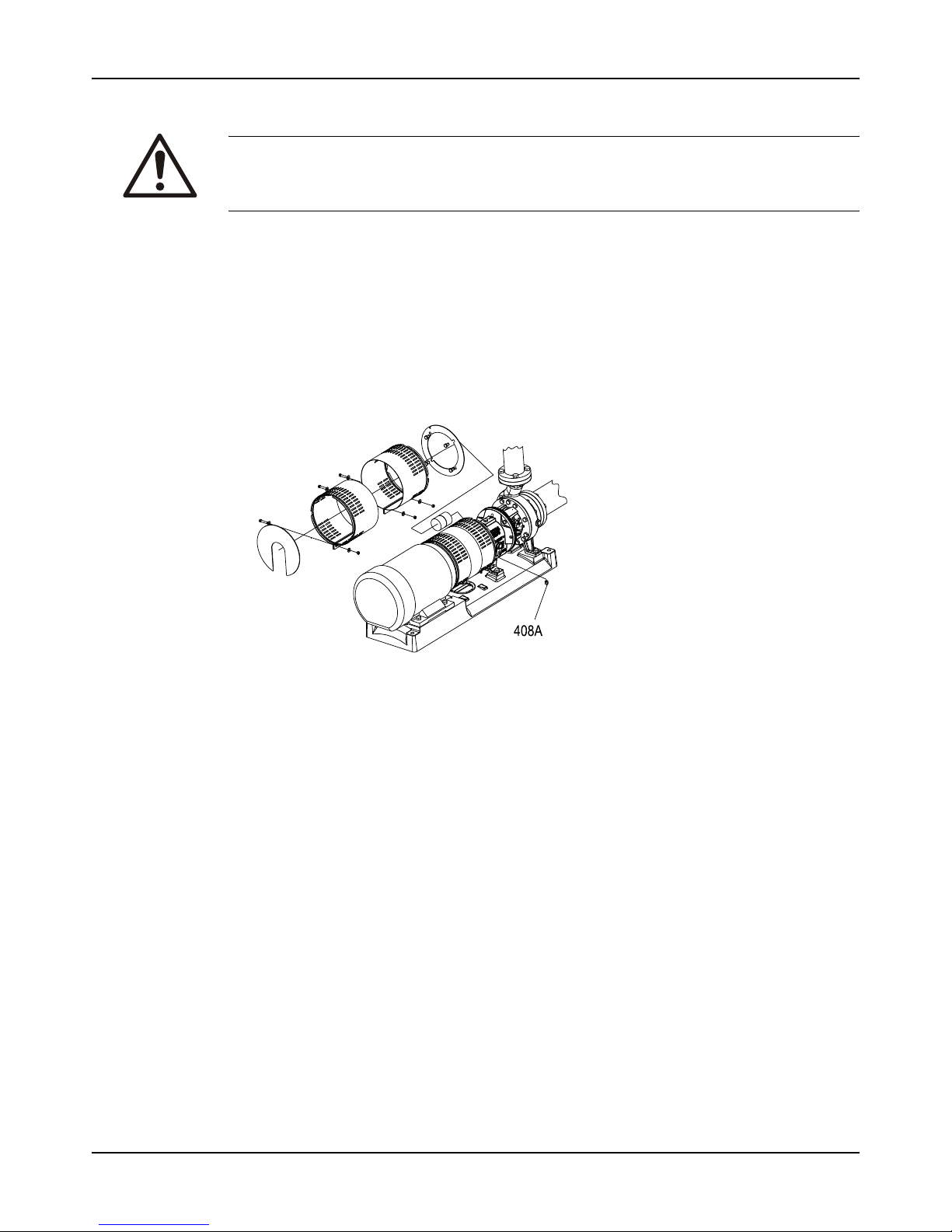
Maintenance
Model 3196 i-FRAME Installation, Operation, and Maintenance Manual74
Remove the back pull-out assembly
WARNING:
Lifting and handling heavy equipment poses a crush hazard. Use caution during lifting and
handling and wear appropriate Personal Protective Equipment (PPE, such as steel-toed shoes,
gloves, etc.) at all times. Seek assistance if necessary.
1. Is your bearing frame oil lubricated?
• If No: Proceed to step 2.
• If Yes:
1. Remove the bearing-frame drain plug (408A) in order to drain oil from the bearing
frame.
2. Replace the plug after the oil is drained.
3. Remove the oil reservoir, if equipped.
Figure 46: Back pull-out assembly removal (oil lubricated bearing frame)
Oil analysis should be part of a preventive maintenance program that determines the cause
of a failure. Save the oil in a clean container for inspection.
2. Does your pump use a C-face adapter?
• If Yes: Place one sling from the hoist through the frame adapter (108) or frame (228A)
for the STi and a second sling from the hoist through the C-face adapter.
Page 77
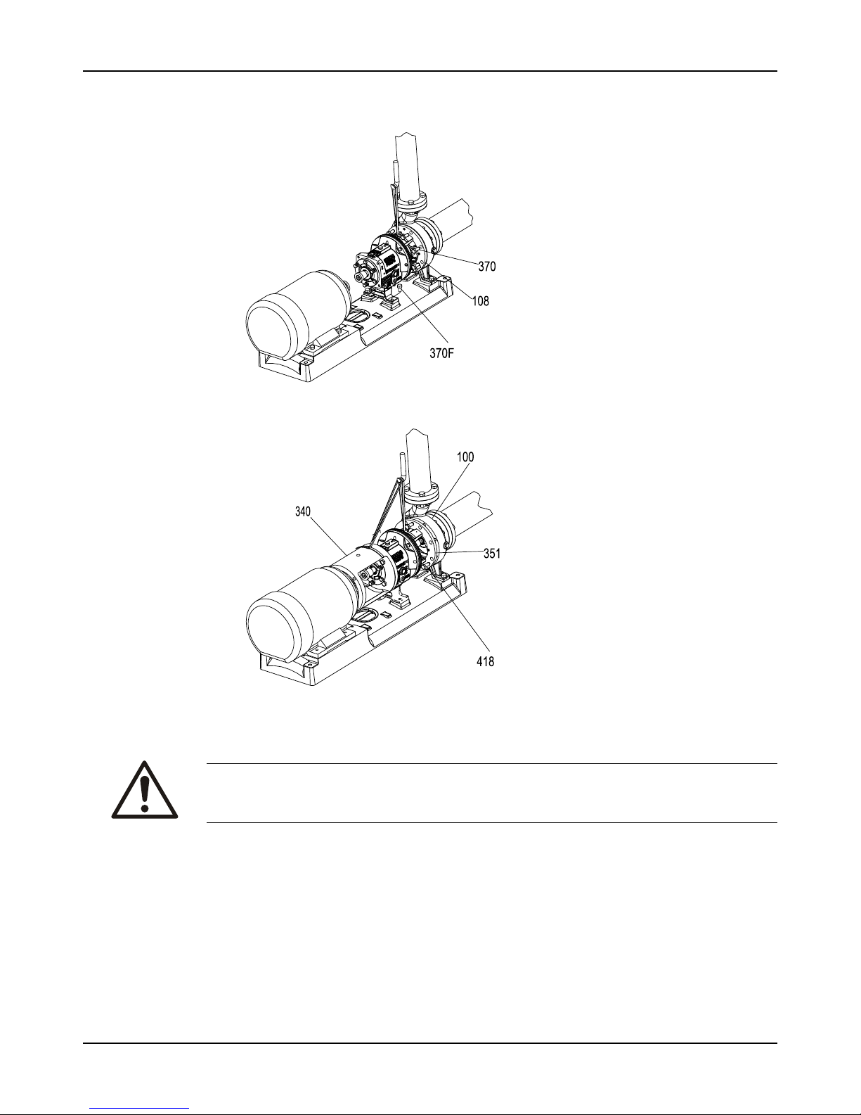
Maintenance
Model 3196 i-FRAME Installation, Operation, and Maintenance Manual 75
• If No: Place a sling from the hoist through the frame adapter (108) or the frame (228A)
for the STi.
Figure 47: Back pull-out assembly removal (with C-face adapter)
Figure 48: Back pull-out assembly removal (without C-face adapter)
3. Remove the hold-down bolts of the bearing frame foot.
4. Remove the casing bolts.
WARNING:
• Risk of severe physical injury or death from explosion of trapped liquid. Never use heat to
remove parts unless explicitly stated in this manual.
5. Tighten the jackscrews evenly, using an alternating pattern, in order to remove the back
pull-out assembly.
You can use penetrating oil if the adapter to the casing joint is corroded.
6. Remove the back pull-out assembly from the casing (100).
7. Mark and remove the shims from under the frame foot and save them for reassembly.
8. Remove and discard the casing gasket.
You will insert a new casing gasket during reassembly.
9. Remove the jackscrews.
10. Clean all gasket surfaces.
Page 78
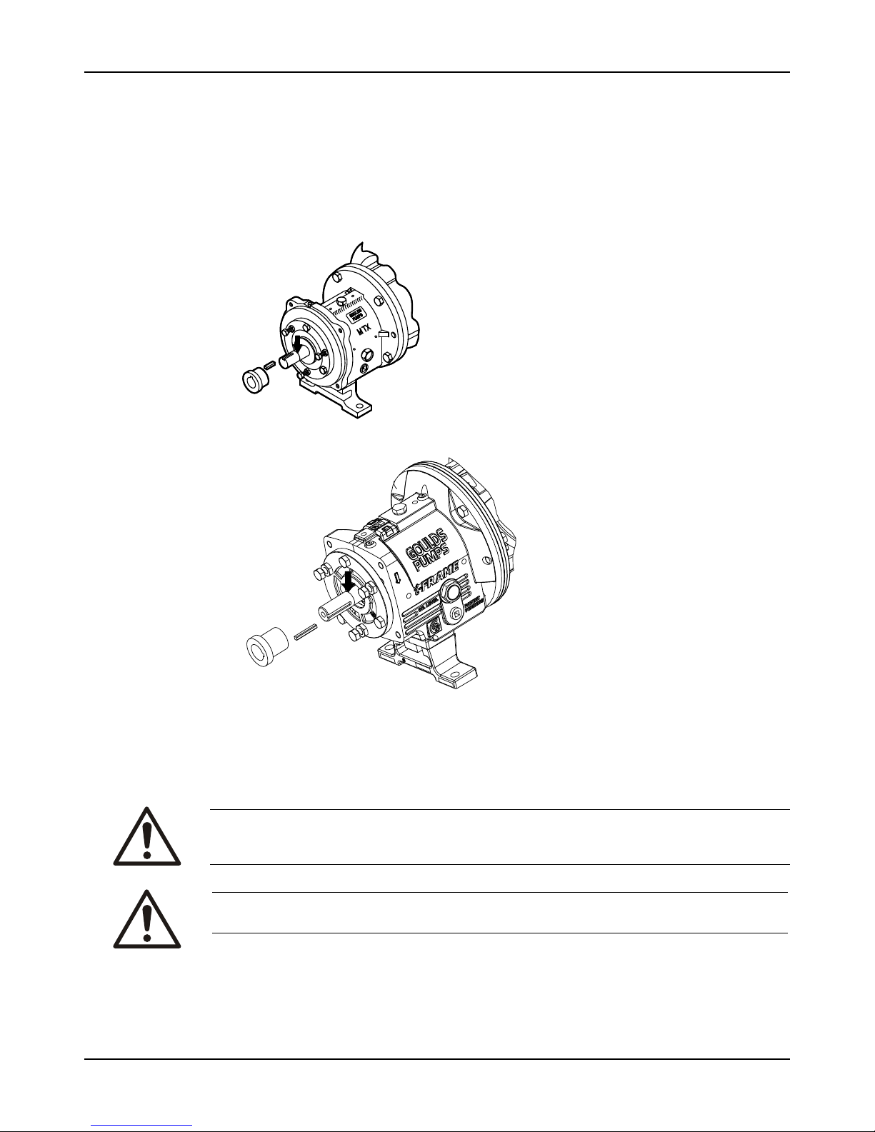
Maintenance
Model 3196 i-FRAME Installation, Operation, and Maintenance Manual76
Clean surfaces prevent the casing gasket from partially adhering to the casing due to
binders and adhesives in the gasket material.
Remove the coupling hub
1. Clamp the frame adapter securely to the workbench.
2. Remove the coupling hub.
Mark the shaft for relocation of the coupling hub during reassembly.
Figure 49: Coupling hub removal
Impeller removal
Remove the impeller (STi, MTi, and LTi)
WARNING:
Risk of severe physical injury or death from explosion of trapped liquid. Never use heat to
remove parts unless explicitly stated in this manual.
CAUTION:
Risk of physical injury from sharp edges. Wear heavy work gloves when handling impellers.
1. Slide the shaft wrench (A05107A or A01676A) over the shaft (122) and key.
2. Rotate the impeller (101) clockwise (viewed from the impeller end of the shaft) and raise
the wrench off of the work surface.
Page 79
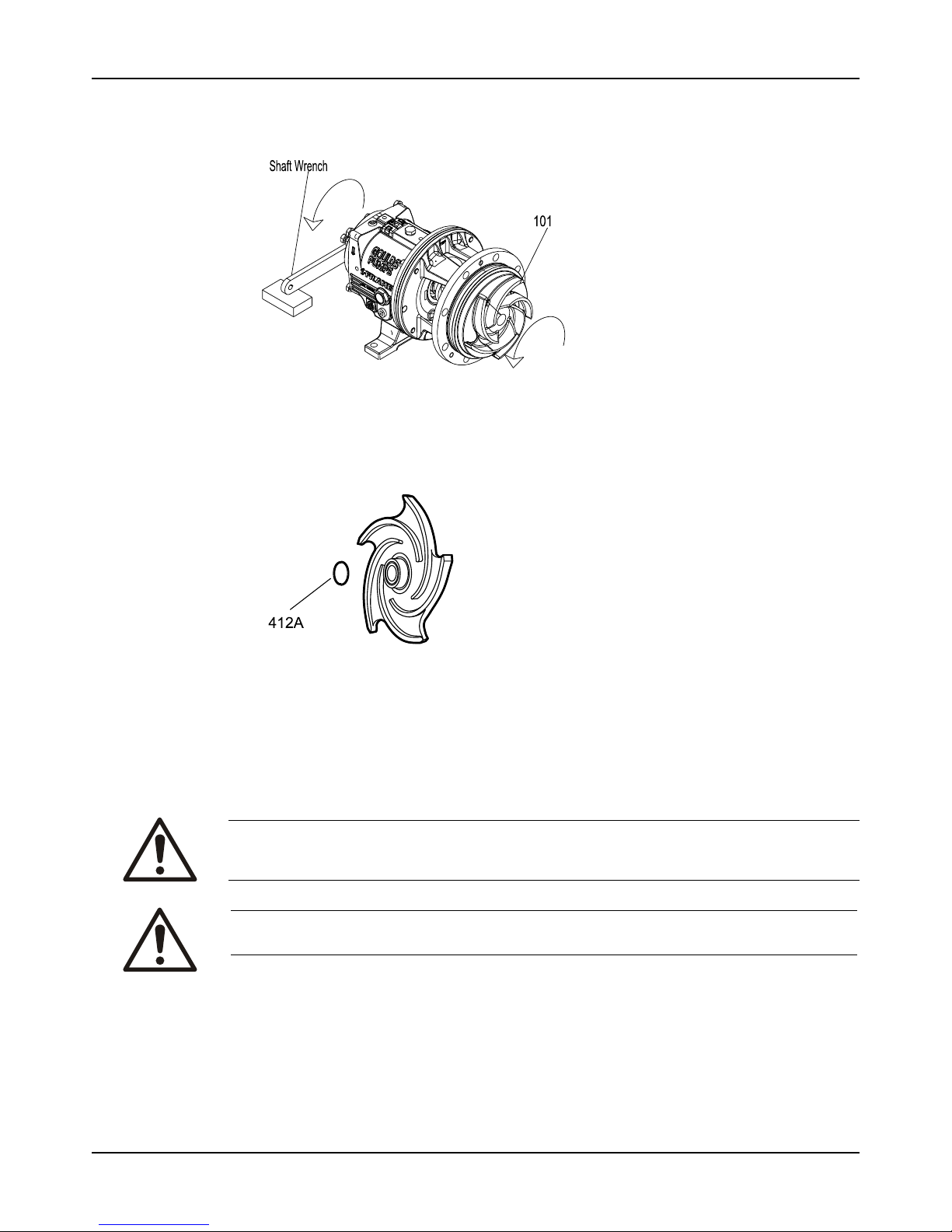
Maintenance
Model 3196 i-FRAME Installation, Operation, and Maintenance Manual 77
3. To loosen the impeller, quickly turn it counter-clockwise (viewed from the impeller end of
the shaft) while impacting the wrench handle on the workbench or a solid block.
Figure 50: Loosen impeller
4. Repeat step 3 until the impeller becomes loose.
5. Remove and discard the impeller O-ring (412A).
You will insert a new O-ring during reassembly.
Figure 51: O-ring for models 3196, HT 3196, NM 3196, 3198, and 3796
If the impeller cannot be removed by the previous methods, cut the shaft between the gland
and the frame, remove the impeller, stuffing-box cover, gland, sleeve, and shaft end as a unit.
Do not apply heat.
Remove the impeller (XLT-i, and i17)
WARNING:
Risk of severe physical injury or death from explosion of trapped liquid. Never use heat to
remove parts unless explicitly stated in this manual.
CAUTION:
Risk of physical injury from sharp edges. Wear heavy work gloves when handling impellers.
Clamp the frame foot (241) to the workbench when you use this method to remove the impeller.
Page 80
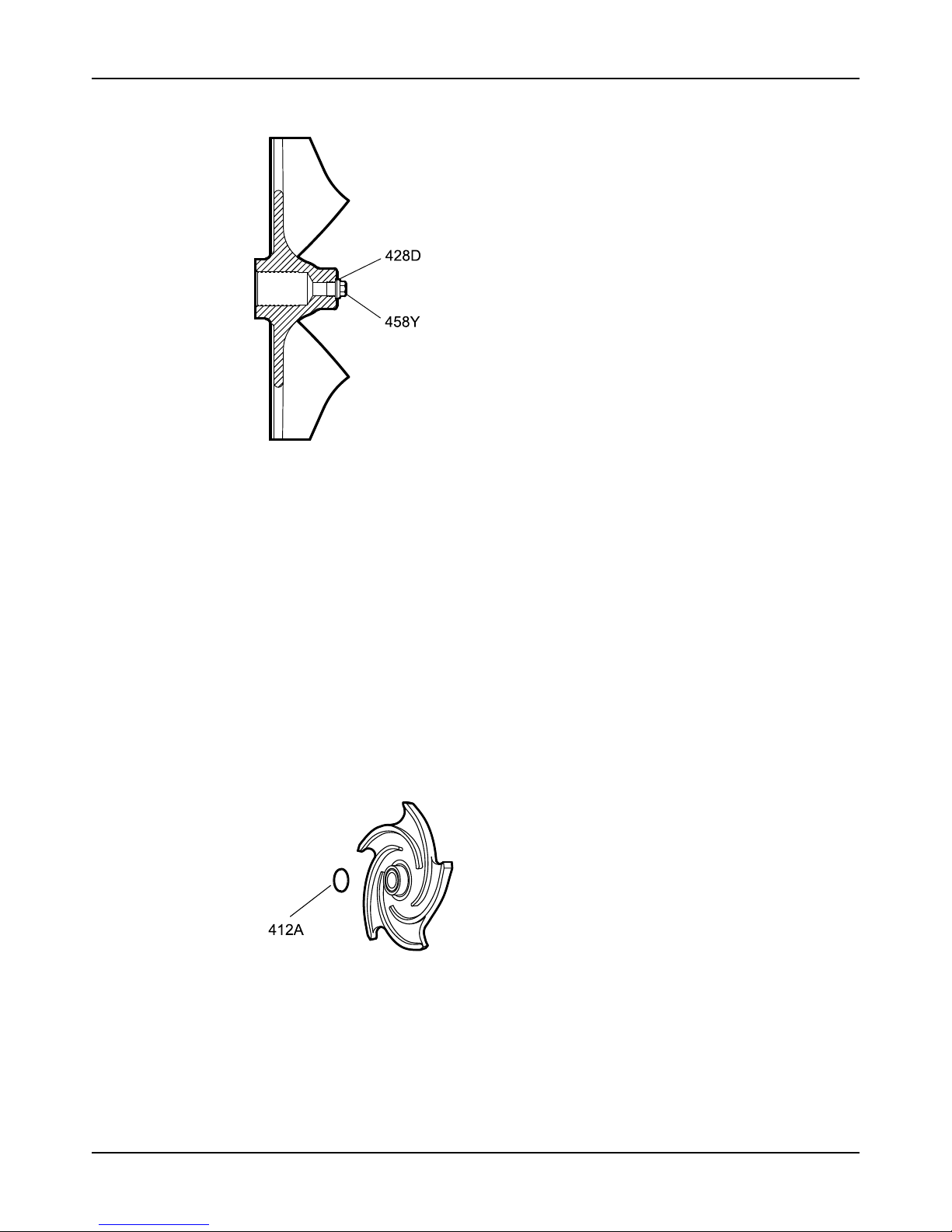
Maintenance
Model 3196 i-FRAME Installation, Operation, and Maintenance Manual78
1. Remove the impeller plug (458Y) from the front of the impeller (101) and discard the PTFE
gasket (428D).
2. Spray penetrating oil through the plug hole into the cavity at the end of the shaft and let it
penetrate for 15 minutes.
3. While waiting, rotate the shaft several times to distribute the oil.
4. Slide the shaft wrench (A05107A) over the shaft (122) and key.
5. Rotate the impeller clockwise (viewed from the impeller end of the shaft) and raise the
wrench off of the work surface.
6. To loosen the impeller, quickly turn the impeller counter-clockwise (viewed from the
impeller end of the shaft) while impacting the wrench handle on the workbench or a solid
block.
7. Repeat step 6 until the impeller becomes loose.
8. If step 6 and 7 do not work then do this:
a) Place a socket wrench over the cast nut on the impeller hub.
b) Turn the impeller counter-clockwise (viewed from the impeller end of the shaft).
Be sure that the impeller wrench rests on the workbench or a solid block and that the power
end is secure on the work surface.
9. Remove and discard the impeller O-ring (412A).
You will insert a new O-ring during reassembly.
Figure 52: O-ring for models 3196 and HT 3196
If the impeller cannot be removed by the previous methods, cut the shaft between the gland
and the frame, remove the impeller, stuffing-box cover, gland, sleeve, and shaft end as a unit.
Do not apply heat.
Page 81
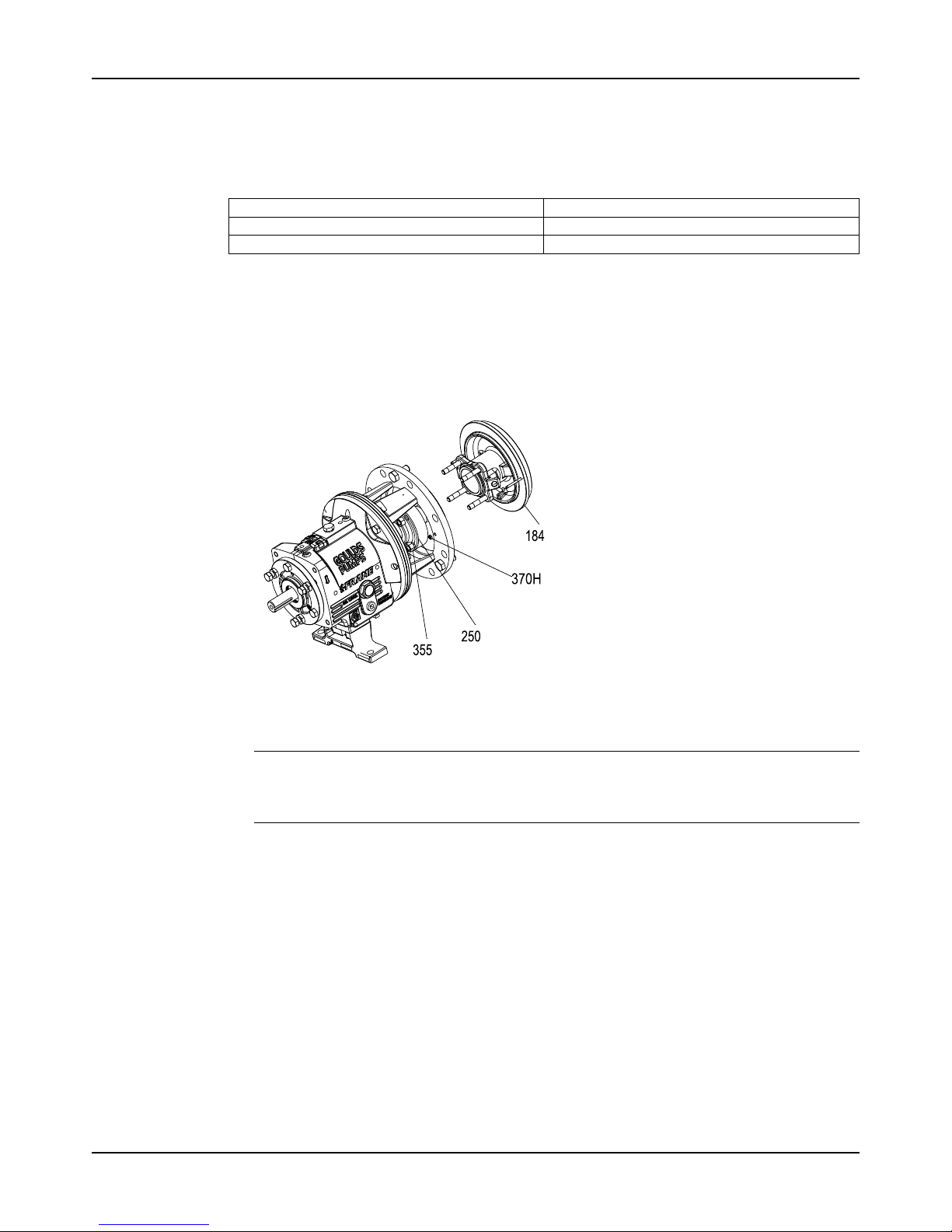
Maintenance
Model 3196 i-FRAME Installation, Operation, and Maintenance Manual 79
Seal-chamber cover removal
Seal-chamber removal procedures
Choose from one of these procedures to remove the seal-chamber cover.
Table 10: Procedures for seal-chamber cover removal by model
Model Procedure
3196, CV 3196, HT 3196, LF 3196, 3796 Removetheseal-chambercover.
NM 3196, 3198 Remove the seal-chamber cover and/or backplate.
Remove the seal-chamber cover (3196, CV 3196, HT 3196, LF 3196,
3796)
1. Remove the gland stud nuts (355).
2. Remove the seal-chamber stud nuts (370H).
3. Remove the seal chamber (184).
Figure 53: Seal chamber cover removal
4. Remove the shaft sleeve (126) if it is used.
The mechanical seal is attached to the sleeve.
NOTICE:
Be careful with the mechanical seal. Carbon or ceramic components are brittle and easily
broken.
5. Remove the rotary portion of the seal from the sleeve by loosening the setscrews and
sliding it off the sleeve.
Refer to the mechanical-seal instructions for more information.
Page 82
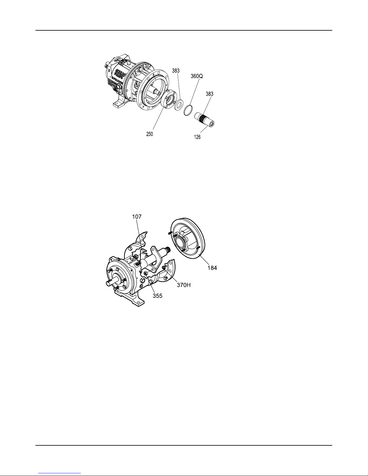
Maintenance
Model 3196 i-FRAME Installation, Operation, and Maintenance Manual80
6. Remove the gland (250), the stationary portion of the seal, and the O-ring (360Q).
Figure 54: Gland removal
Remove the stuffing-box cover (3196, CV 3196, HT 3196, LF 3196,
3796)
1. Remove the gland nuts (355) and the gland (107).
2. Remove the stuffing-box-cover nuts (370H).
3. Remove the stuffing-box cover (184).
Figure 55: Stuffing box cover removal
Page 83
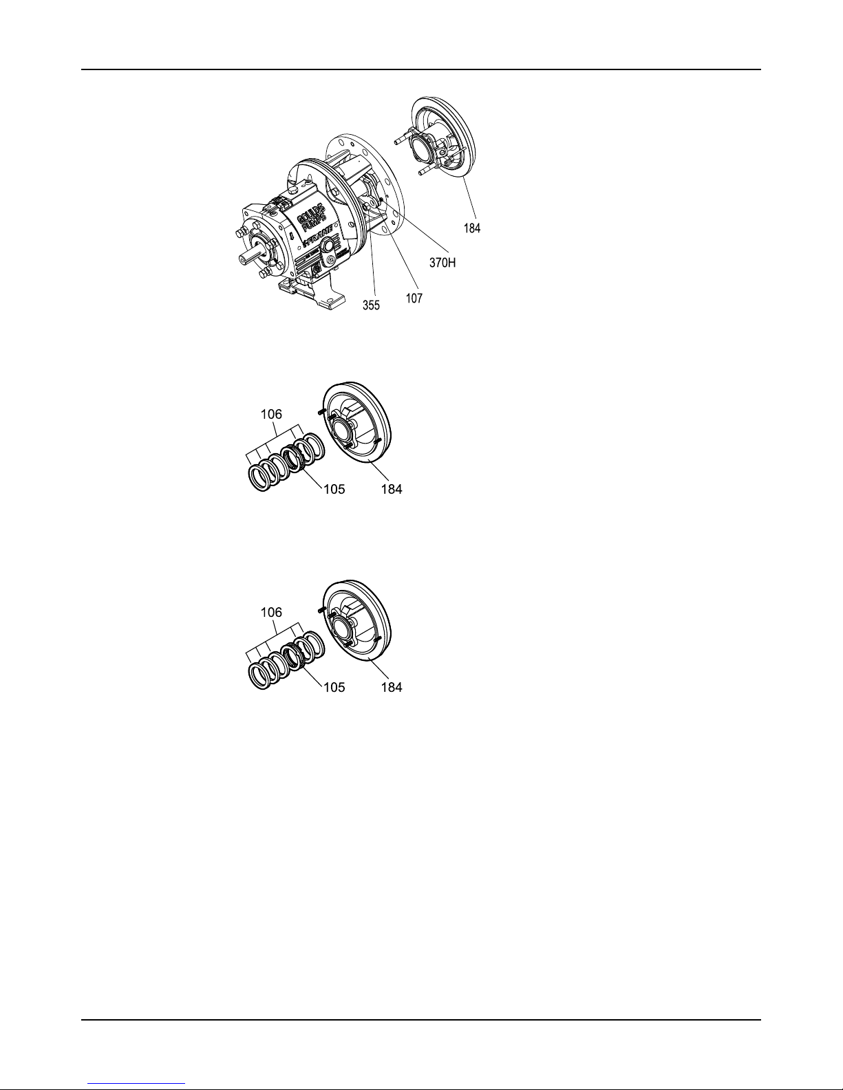
Maintenance
Model 3196 i-FRAME Installation, Operation, and Maintenance Manual 81
Figure 56: Stuffing box cover removal
4. Remove the shaft sleeve (126).
Figure 57: Remove the shaft sleeve
5. Remove the packing (106) and lantern ring (105) from the stuffing-box cover (184).
A lantern ring does not come with self-lubricating graphite packing.
Figure 58: Packing and lantern ring removal
Remove the dynamic seal
1. Remove the stud nuts (370H).
Page 84
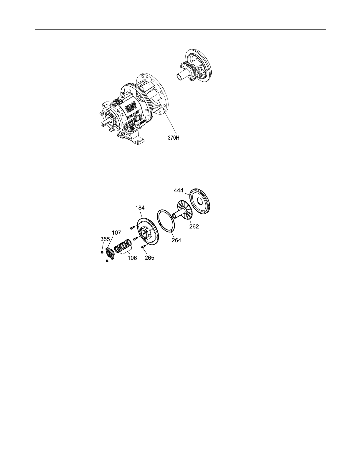
Maintenance
Model 3196 i-FRAME Installation, Operation, and Maintenance Manual82
2. Remove the dynamic-seal assembly.
Figure 59: Dynamic seal removal
3. Remove the socket head cap screws (265).
4. Remove the packed stuffing box cover (184) and gasket (264).
5. Remove the repeller (262) from the backplate (444).
Figure 60: Repeller removal
Remove the frame adapter (MTi, LTi, XLT-i, i17)
The 3198 frame adapter is not interchangeable with the adapter of any other model.
1. Remove the dowel pins (469B) and the bolts (370B).
2. Remove the frame adapter (108).
3. Remove and discard the gasket (360D).
Page 85
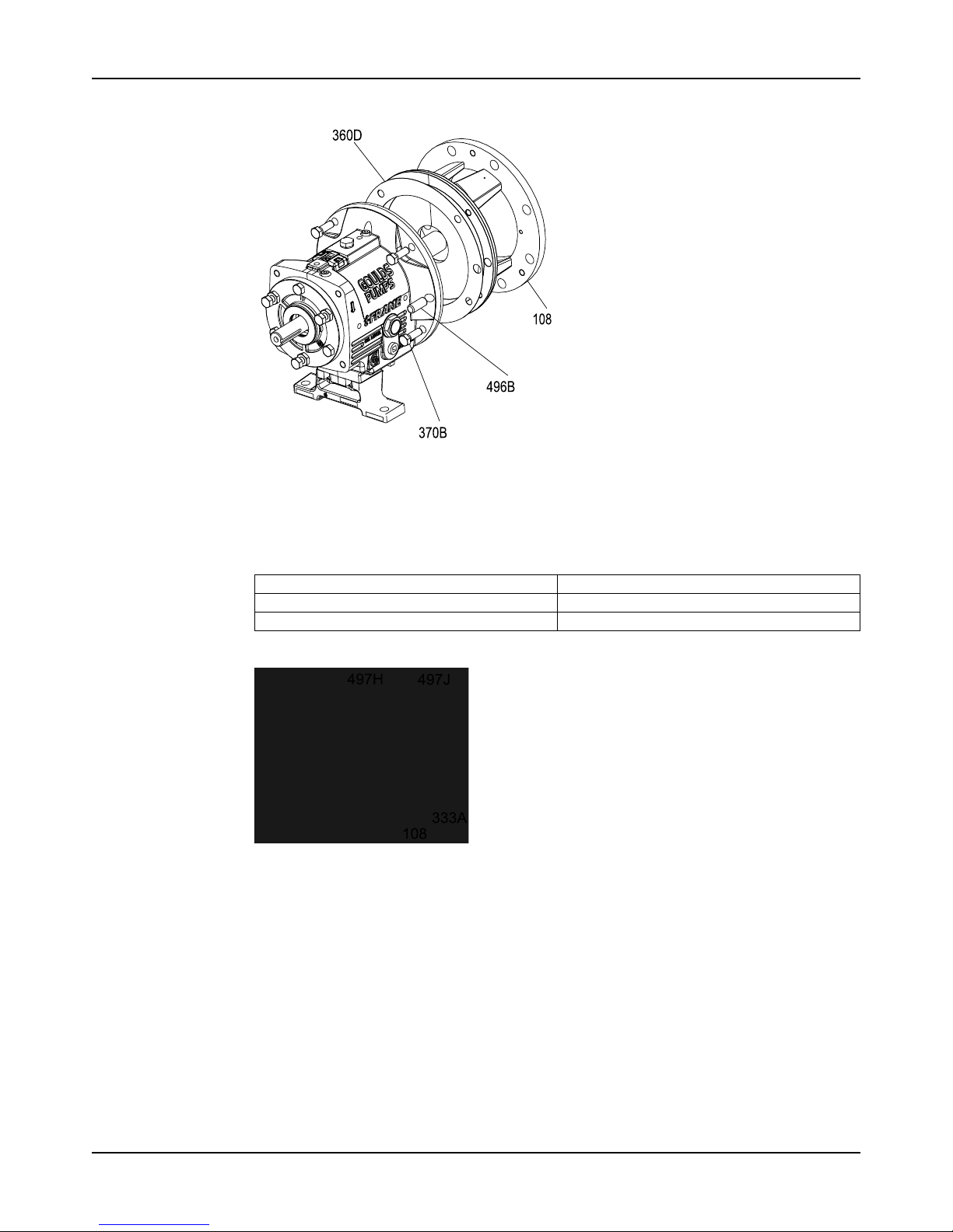
Maintenance
Model 3196 i-FRAME Installation, Operation, and Maintenance Manual 83
You will install a new gasket during reassembly.
Remove the inboard labyrinth oil seal
Labyrinth oil-seal O-rings are part of the 3196 maintenance kits, and they are sold separately.
1. Determine the fit of your labyrinth oil seal.
Table 11: Labyrinth oil-seal fit
Model Type of fit
STi O-ringfitintothebearing-frameadapter(228A)
MTi, LTi, XLT-i and i17 O-ring fit into the frame adapter
2. Remove the O-rings (497H and 497J) and the seal (333A).
Figure 61: O-ring removal
Disassemble the power end (STi, MTi)
1. Remove the clamp screws (370C) and back off the jam nuts (423).
2. Tighten the jack screws (370D) evenly to move the bearing housing (134) out of the bearing
frame (228A).
Page 86
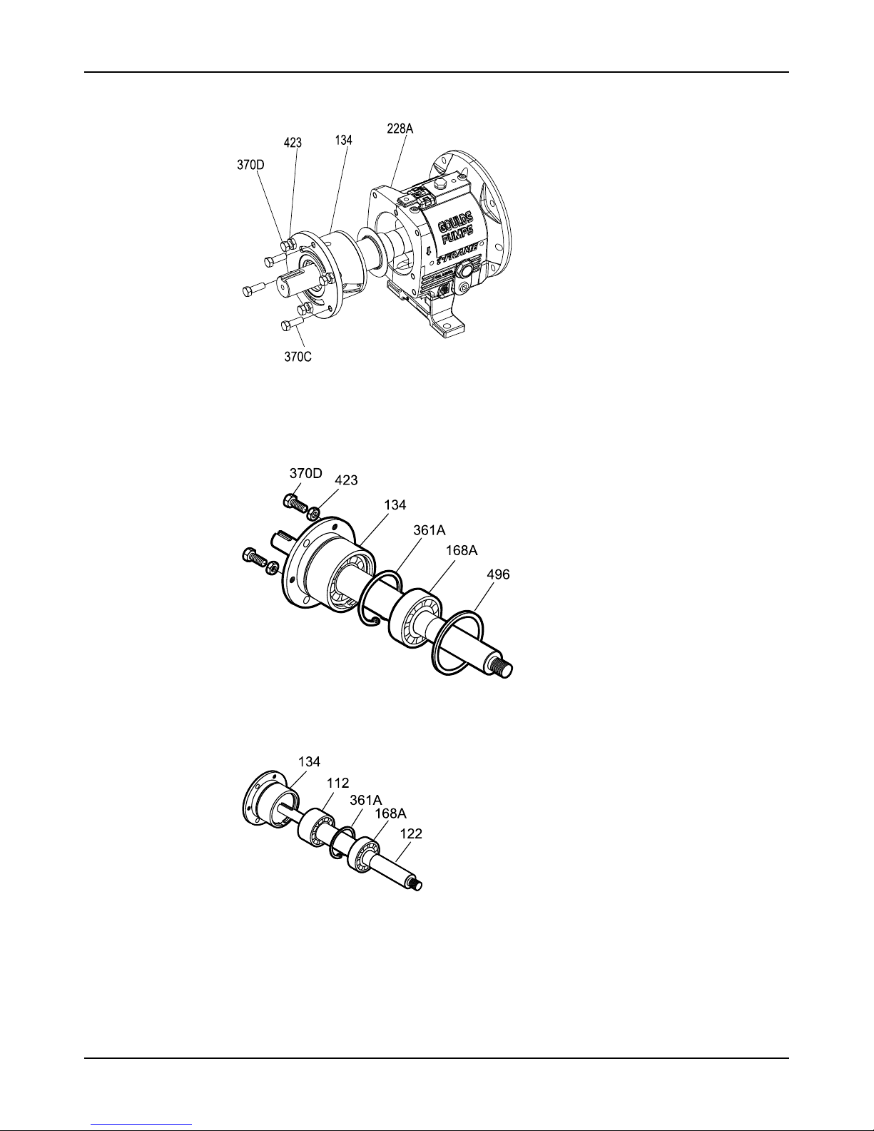
Maintenance
Model 3196 i-FRAME Installation, Operation, and Maintenance Manual84
3. Remove the shaft assembly from the bearing frame (228A).
Figure 62: Shaft assembly removal
4. Remove the jack screws (370D) with nuts (423).
5. Remove the bearing housing O-ring (496) and the bearings.
6. Remove the outboard bearing retaining snap ring (361A).
Figure 63: Outboard bearing retaining snap ring removal
7. Remove the bearing housing (134) and bearings (112A and 168A) from the shaft (122).
Figure 64: Bearing housing and bearings removal
8. Remove the bearing locknut (136) and bearing lock washer (382).
9. Remove the inboard bearing (168A).
10. Remove the outboard bearing (112A).
Page 87
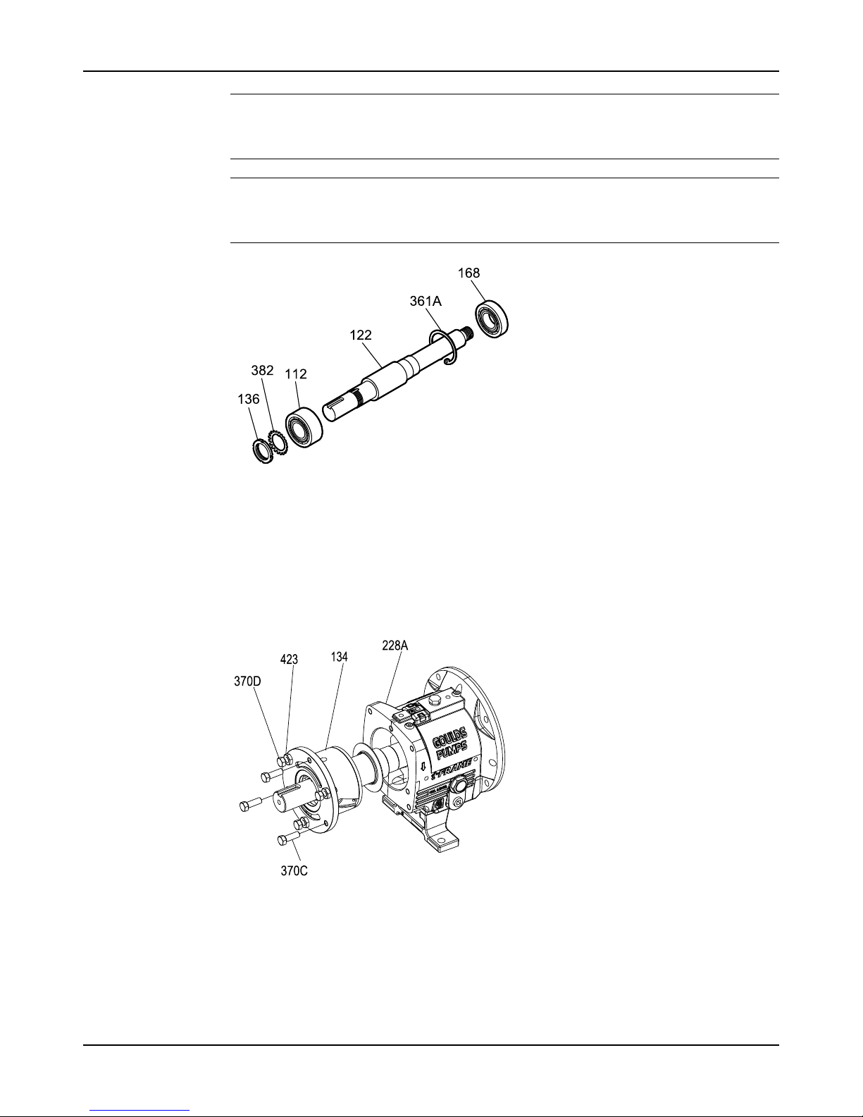
Maintenance
Model 3196 i-FRAME Installation, Operation, and Maintenance Manual 85
NOTICE:
Use force only on the inner race when pressing bearings from the shaft. Failure to do so
may result in equipment damage.
NOTICE:
Do not reuse bearings if removed from shaft. Doing so may result in equipment damage.
Replace the bearings before reassembly.
Figure 65: Outboard bearing removal
Disassemble the power end (STi and MTi with duplex bearings)
1. Remove the clamp screws (370C) and back off the jam nuts (423).
2. Tighten the jack screws (370D) evenly to move the bearing housing (134) out of the bearing
frame (228A).
3. Remove the shaft assembly from the bearing frame (228A).
Figure 66: Shaft assembly removal
Page 88
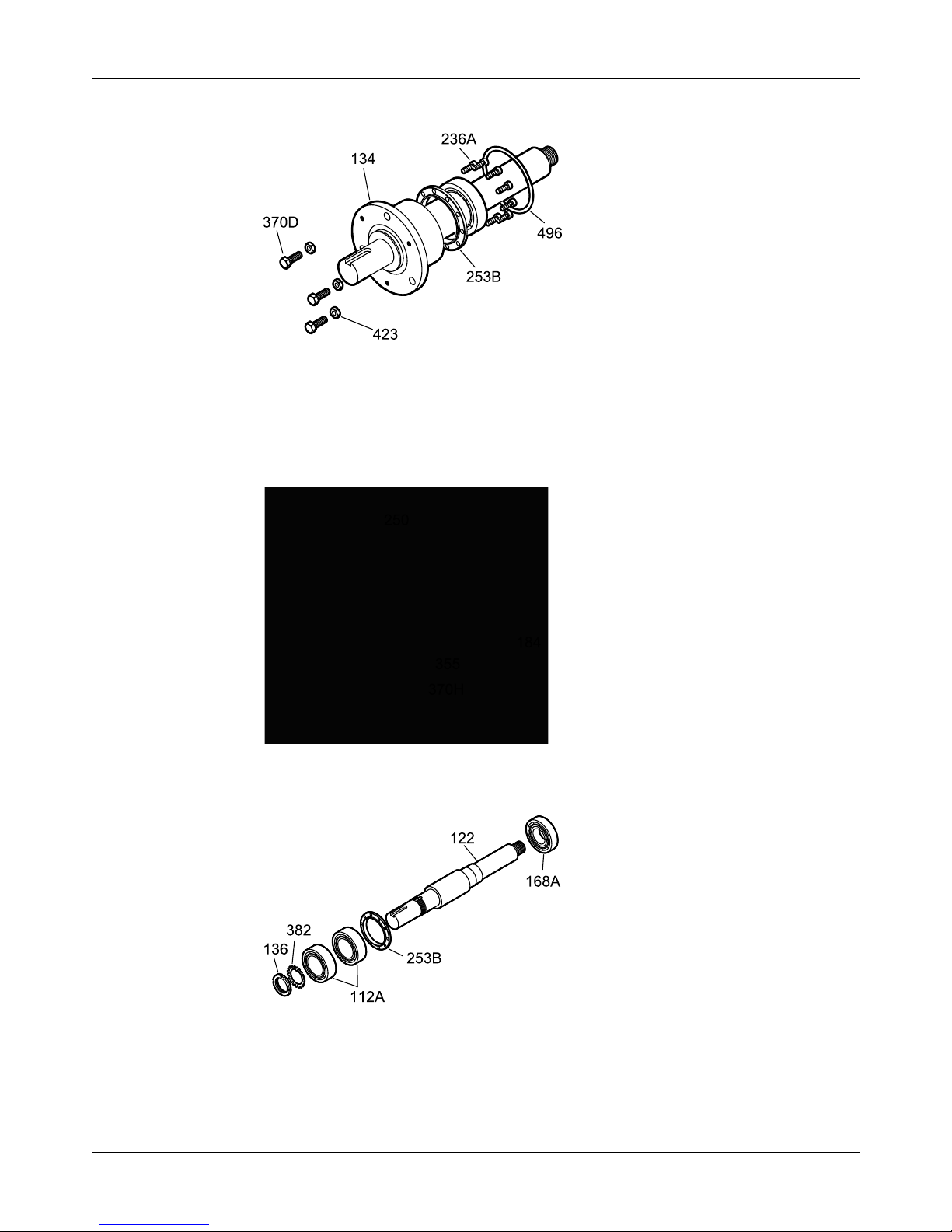
Maintenance
Model 3196 i-FRAME Installation, Operation, and Maintenance Manual86
4. Remove the jack screws (370D) with the nuts (423).
Figure 67: Jack screw removal
5. Remove the bearing housing O-ring (496).
6. Remove the clamp ring screws (236A) and separate the clamp ring (253B) from the bearing
housing (134).
You must remove the bearings before you can remove the clamp ring from the shaft.
7. Remove the bearing housing (134) and the bearings (112A and 168A) from the shaft (122).
Figure 68: Bearing housing and bearing removal
8. Remove the inboard bearing (168A).
Figure 69: Inboard bearing removal
9. Remove the bearing locknut (136) and bearing lockwasher (382).
10. Remove the outboard bearings (112A).
Page 89
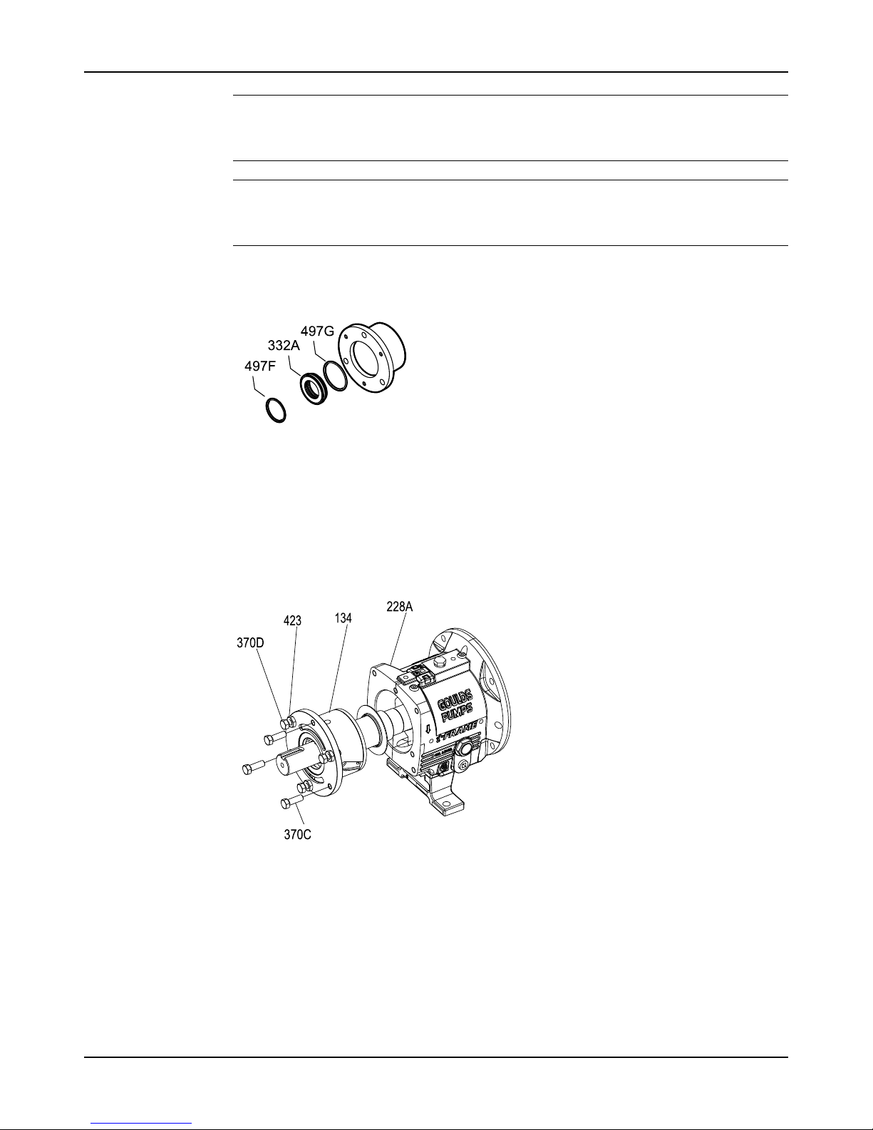
Maintenance
Model 3196 i-FRAME Installation, Operation, and Maintenance Manual 87
NOTICE:
Use force only on the inner race when pressing bearings from the shaft. Failure to do so
may result in equipment damage.
NOTICE:
Do not reuse bearings if removed from shaft. Doing so may result in equipment damage.
Replace the bearings before reassembly.
11. Remove the outboard labyrinth oil seal (332A) from the bearing housing (134).
Remove the O-rings (497F and 497G) if it is necessary. Labyrinth oil seal O-rings are part
of the 3196 maintenance kits and they are sold separately.
Figure 70: Outboard labyrinth oil seal removal
Disassemble the power end (LTi)
1. Remove the clamp screws (370C) and back off the jam nuts (423).
2. Evenly tighten the jack screws (370D) to move the bearing housing (134) out of the bearing
frame (228A).
3. Remove the shaft assembly from the bearing frame (228A).
Figure 71: Shaft assembly removal
4. Remove the jack screws (370D) with the nuts (423).
5. Remove the clamp-ring screws (236A) and separate the clamp ring (253B) from the
bearing housing (134).
Page 90
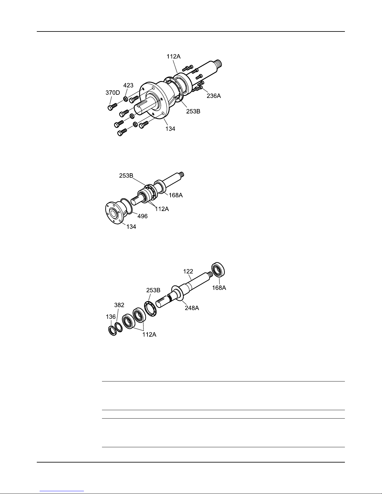
Maintenance
Model 3196 i-FRAME Installation, Operation, and Maintenance Manual88
You must remove the bearings before you can remove the clamp ring from the shaft.
Figure 72: Clamp ring removal
6. Remove the bearing housing (134) and the bearings (112A and 168A) from the shaft (122).
Figure 73: Bearing housing and bearing removal
7. Remove the bearing housing O-ring (496) and the inboard bearing (168A).
Figure 74: O-ring removal
8. Remove the flinger so that the flinger seating surface on the shaft can be cleaned.
9. Remove the bearing locknut (136) and the bearing lockwasher (382).
10. Remove the outboard bearings (112A) and the clamp ring (253B).
NOTICE:
Use force only on the inner race when pressing bearings from the shaft. Failure to do so
may result in equipment damage.
NOTICE:
Do not reuse bearings if removed from shaft. Doing so may result in equipment damage.
Replace the bearings before reassembly.
Page 91
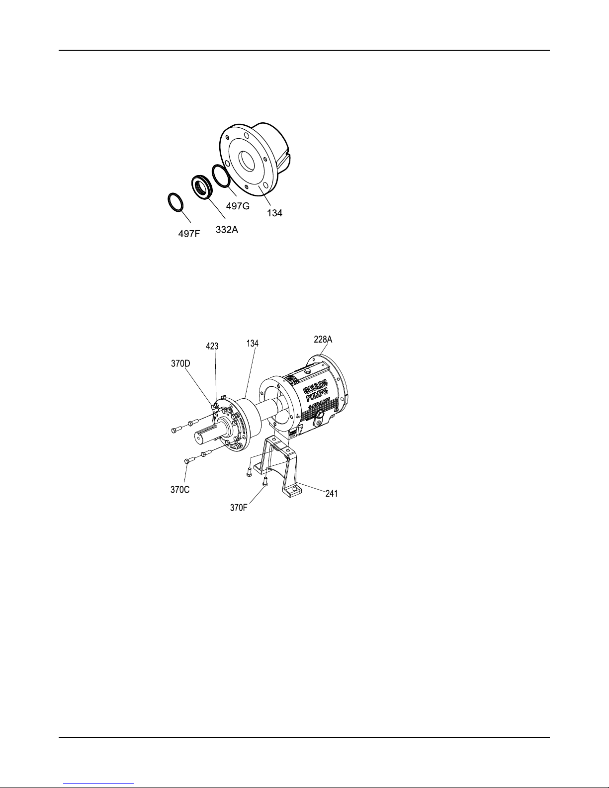
Maintenance
Model 3196 i-FRAME Installation, Operation, and Maintenance Manual 89
11. Remove the outboard labyrinth oil seal (332A) from the bearing housing (134).
12. Remove the O-rings (497F and 497G) if it is necessary.
Labyrinth oil-seal O-rings are part of the 3196 maintenance kits, and they are sold
separately.
Figure 75: O-ring removal
Disassemble the power end (XLT-i and i17)
1. Remove the bearing frame from the frame foot (241) using the frame-foot bolts (370F).
2. Remove the clamp screws (370C) and back off the jam nuts (423).
3. Tighten the jack screws (370D) evenly to move the bearing housing (134) out of the bearing
frame (228A).
4. Remove the shaft assembly from the bearing frame (228A).
5. Remove the jack screws (370D), the nuts (423), and the bearing housing O-ring.
Page 92
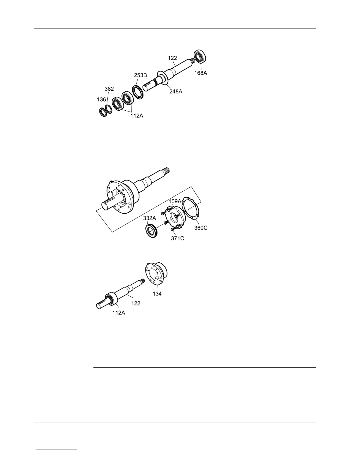
Maintenance
Model 3196 i-FRAME Installation, Operation, and Maintenance Manual90
6. Remove the inboard bearing (168A).
7. Remove the bolts (371C), the bearing end cover (109A), and the gasket (360C).
8. Remove the outboard labyrinth oil seal (332A) from the end cover (109A).
9. Remove the O-rings (497F and 497G) if it is necessary.
Labyrinth oil-seal O-rings are part of the 3196 maintenance kits, and they are sold
separately.
10. Remove the bearing housing (134) and the bearing (112A) from the shaft (122).
11. Remove the bearing locknut (136), the bearing lockwasher (382), and the outboard bearing
(112A).
NOTICE:
Use force only on the inner race when pressing bearings from the shaft. Failure to do so
may result in equipment damage.
Page 93
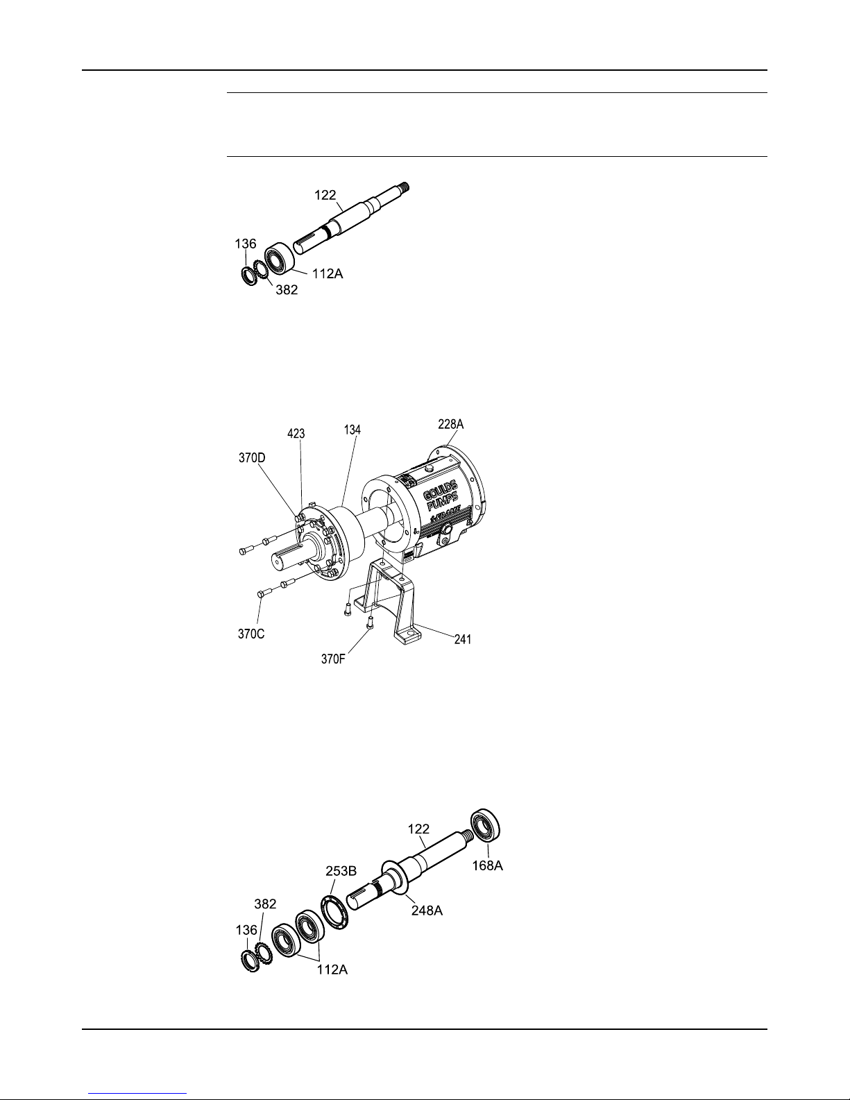
Maintenance
Model 3196 i-FRAME Installation, Operation, and Maintenance Manual 91
NOTICE:
Do not reuse bearings if removed from shaft. Doing so may result in equipment damage.
Replace the bearings before reassembly.
Disassemble the power end (XLT-i and i17 with duplex bearings)
1. Remove the bearing frame to frame foot (241) using the frame-foot bolts (370F).
2. Remove the clamp screws (370C) and back off the jam nuts (423).
3. Tighten the jack screws (370D) evenly to move the bearing housing (134) out of the bearing
frame (228A).
4. Remove the shaft assembly from the bearing frame (228A).
5. Remove the jack screws (370D) and the nuts (423).
6. Remove the bearing housing O-ring (496) and the inboard bearing (168A).
Page 94
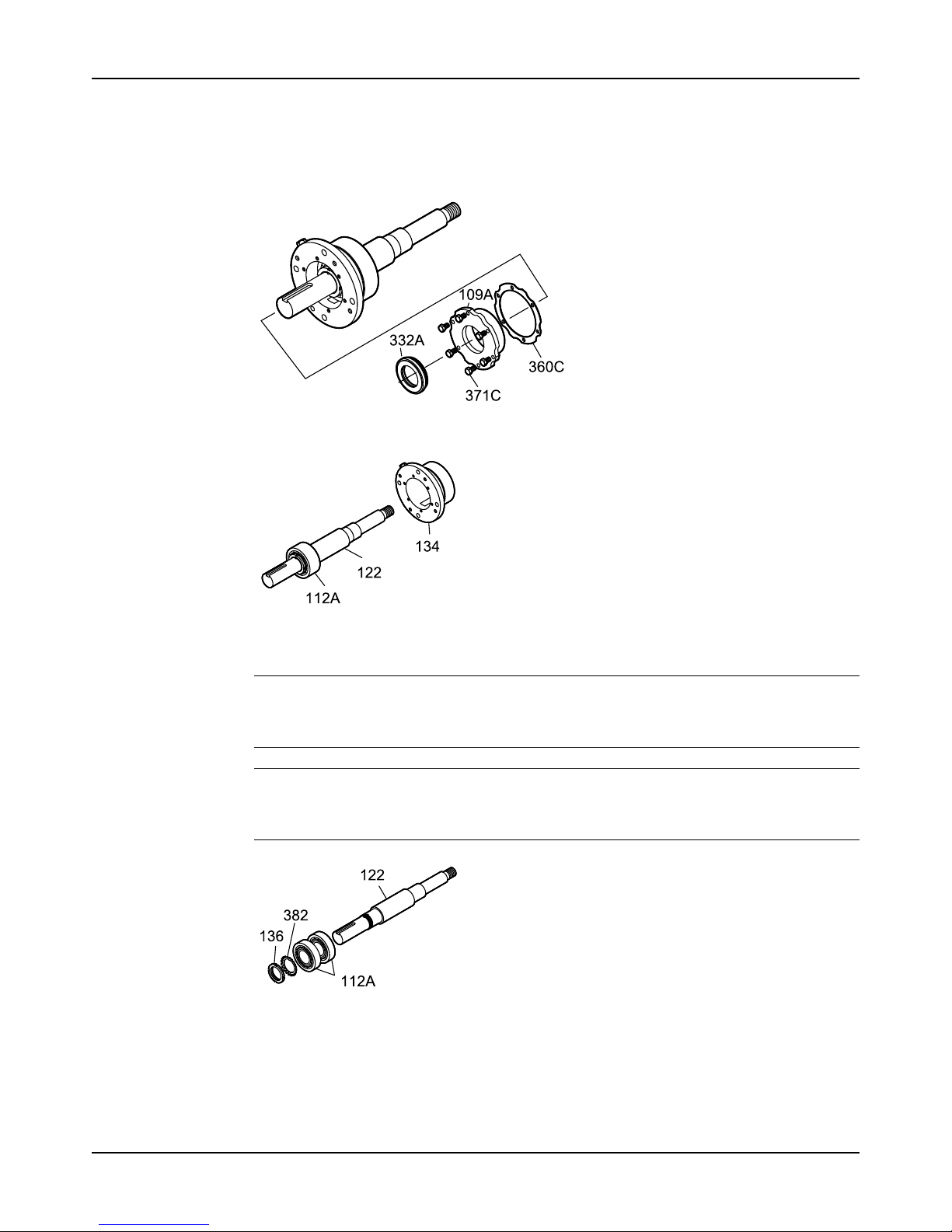
Maintenance
Model 3196 i-FRAME Installation, Operation, and Maintenance Manual92
7. Remove the bolts (371C), the end cover (109A), and the gasket (360C).
8. If necessary, remove the outboard labyrinth oil seal (332A) from the end cover (109A) and
remove the O-rings (497F and 497G).
Labyrinth oil-seal O-rings are part of the 3196 maintenance kits, or they are sold
separately.
9. Remove the bearing housing (134) and bearings (112A) from the shaft (122) .
10. Remove the bearing locknut (136), the bearing lockwasher (382), and the outboard bearing
(112A).
NOTICE:
Use force only on the inner race when pressing bearings from the shaft. Failure to do so
may result in equipment damage.
NOTICE:
Do not reuse bearings if removed from shaft. Doing so may result in equipment damage.
Replace the bearings before reassembly.
Disassemble the bearing frame
1. Remove these plugs from the bearing frame (228A).
• oil-fill plug (113A)
Page 95
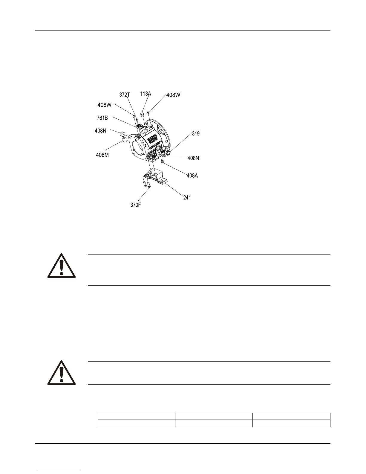
Maintenance
Model 3196 i-FRAME Installation, Operation, and Maintenance Manual 93
• oil-drain plug (408A)
• sight-oiler plug (408J)
• four oil mist/grease connection plugs (408H)
• oil-cooler inlet and outlet plugs (408L and 408M) or oil cooler
2. For the MTi and LTi models, remove the bearing frame foot-to-frame bolts (370F) and the
frame foot (241).
Figure 76: Plug removal
Guidelines for i-ALERT®Condition Monitor disposal
Precautions
WARNING:
• Explosive hazard and risk of personal injury. Heating to high temperatures could cause
combustion of the condition monitor. Never heat the condition monitor to temperatures in
excess of 149°C | 300°F or dispose of in a fire.
Guidelines
The battery contained in the condition monitor does not contain enough lithium to qualify as
reactive hazardous waste. Use these guidelines when disposing of the condition monitor.
• The condition monitor is safe for disposal in the normal municipal waste stream.
• Adhere to local laws when you dispose of the condition monitor.
Disassemble the C-face adapter
WARNING:
Risk of personal injury and equipment damage from dropping or tipping motor. The motor must
be properly supported with a clean, uncorroded eye bolt or a strap under both ends.
1. Loosen the motor-mounting bolts and remove the motor.
Table 12: Required number of motor-mounting bolts
This table shows the number of motor-mounting bolts.
Pump frame Motor frame Number of bolts
STi All 4
Page 96
Maintenance
Model 3196 i-FRAME Installation, Operation, and Maintenance Manual94
Pump frame Motor frame Number of bolts
MTi and LTi 143-286 4
324-365 8
2. Loosen the bolts attached to the bearing-frame flange and remove the C-face adapter from
the bearing frame.
Pre-assembly inspections
Guidelines
Before you assemble the pump parts, make sure you follow these guidelines:
• Inspect the pump parts according to the information in these pre-assembly topics before
you reassemble your pump. Replace any part that does not meet the required criteria.
• Make sure that the parts are clean. Clean the pump parts in solvent in order to remove oil,
grease, and dirt.
NOTICE:
Protect machined surfaces while cleaning the parts. Failure to do so may result in
equipment damage.
Replacement guidelines
Casing check and replacement
WARNING:
Risk of death or serious injury. Leaking fluid can cause fire and/or burns. Inspect and ensure
gasket sealing surfaces are not damaged and repair or replace as necessary.
Inspect the casing for cracks and excessive wear or pitting. Thoroughly clean gasket surfaces
and alignment fits in order to remove rust and debris.
Repair or replace the casing if you notice any of these conditions:
• Localized wear or grooving that is greater than 3.2 mm | 1/8 in. deep
• Pitting that is greater than 3.2 mm | 1/8 in. deep
• Irregularities in the casing-gasket seat surface
Casing areas to inspect
The arrows point to the areas to inspect for wear on the casing:
Page 97
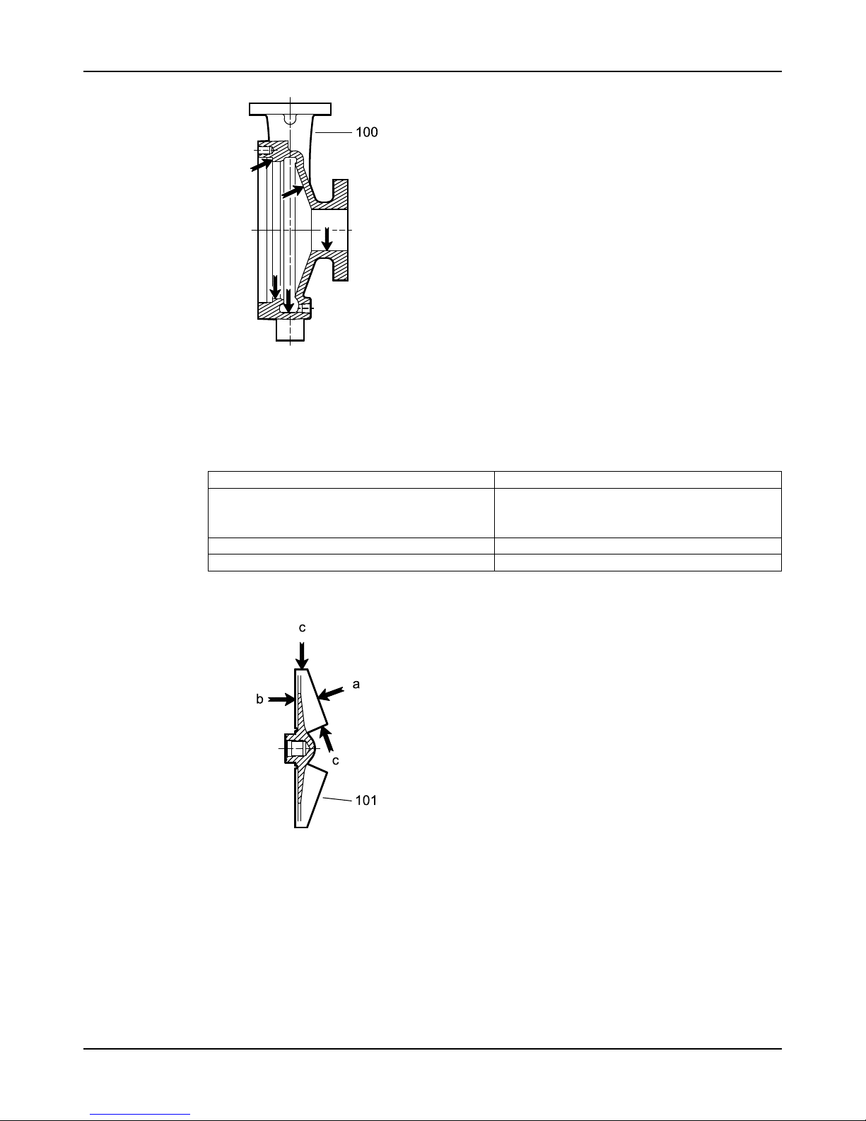
Maintenance
Model 3196 i-FRAME Installation, Operation, and Maintenance Manual 95
Figure 77: 3196, HT 3196, LF 3196, NM 3196, and 3198 casing
Impeller replacement
This table shows the criteria for replacing the impeller:
Impeller parts When to replace
Impeller vanes
• When grooved deeper than 1.6 mm | 1/16 in.,
or
• When worn evenly more than 0.8 mm | 1/32 in.
Pumpout vanes When worn or bent more than 0.8 mm | 1/32 in.
Vane edges When you see cracks, pitting, or corrosion damage
Impeller areas to inspect
Figure 78: Areas to inspect for wear on the 3196 impeller.
Frame adapter check and replacement
• Replace the frame adapter if it has cracks or excessive corrosion damage.
• Make sure the gasket surface is clean.
Page 98
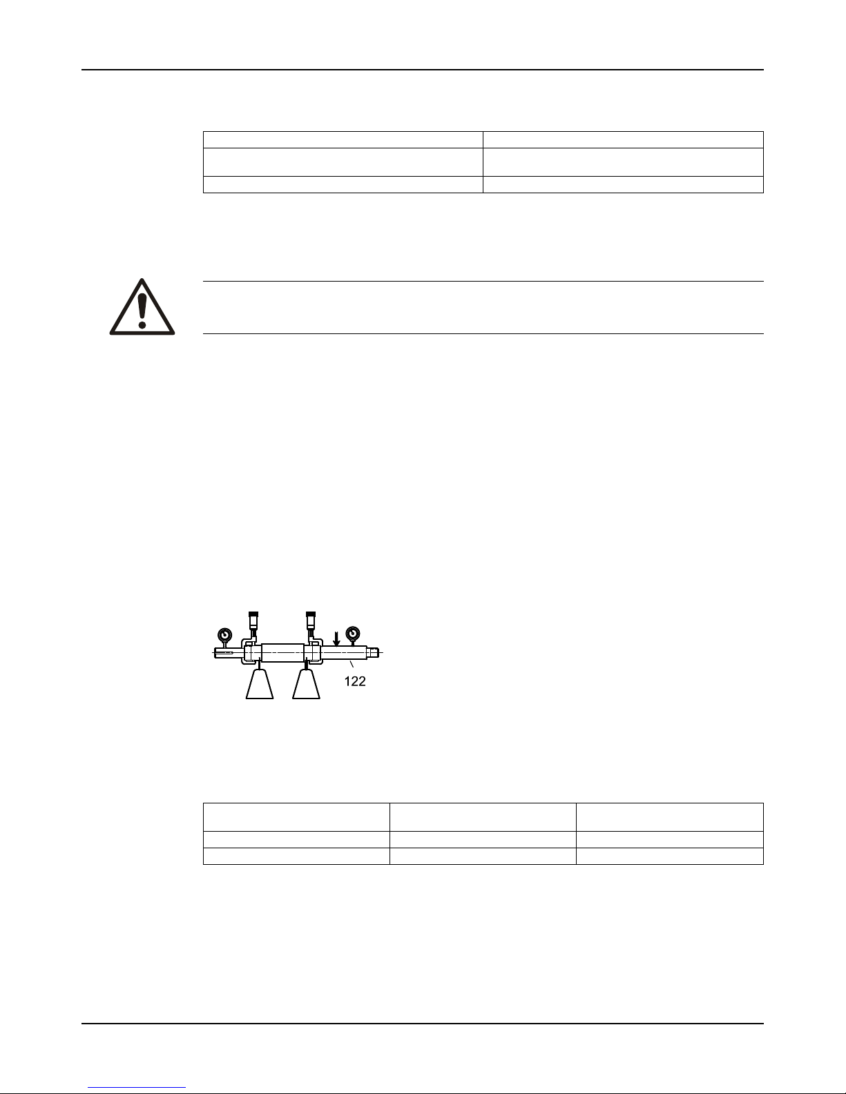
Maintenance
Model 3196 i-FRAME Installation, Operation, and Maintenance Manual96
Dynamic-seal repeller replacement
This table shows the criteria for replacing dynamic-seal repeller parts for the 3196, CV 3196, and LF 3196
pump models.
Dynamic seal part When to replace
Dynamic-seal repeller vane The grooves are deeper than 1.6 mm | 1/16 in. or
are worn evenly more than 0.8 mm | 1/32 in..
Sleeve surface The surface has grooves, pitting, or other damage.
Labyrinth seal replacement
Replace the labyrinth-seal O-ring if it has cuts and cracks.
Gaskets, O-rings, and seats replacement
WARNING:
Risk of death or serious injury. Leaking fluid can cause fire and/or burns. Replace all gaskets
and O-rings at each overhaul or disassembly.
• Replace all gaskets and O-rings at each overhaul and disassembly.
• Inspect the seats. They must be smooth and free of physical defects.
In order to repair worn seats, skin cut them in a lathe while you maintain dimensional
relationships with other surfaces.
• Replace parts if the seats are defective.
Shaft and sleeve replacement guidelines
Two types of sleeves
The 3198 is offered with either a metallic sleeve that uses the standard 3196 shaft or a PTFE
sleeve. The PTFE sleeve requires a special shaft and a different inboard labyrinth oil seal.
Shaft measurements check
Replace the shaft (122) if any measurements exceed acceptable values. See Bearing fits and
tolerances.
Figure 79: Shaft measurements check
Straightness check
Replace the shaft (122) if runout exceeds the values in this table:
Table 13: Shaft runout tolerances for sleeve fit and coupling fit
Sleeve fit in millimeters | inches Coupling fit in millimeters |
inches
With sleeve 0.025 | 0.001 0.025 | 0.001
Without sleeve 0.051 | 0.002 0.025 | 0.001
Page 99
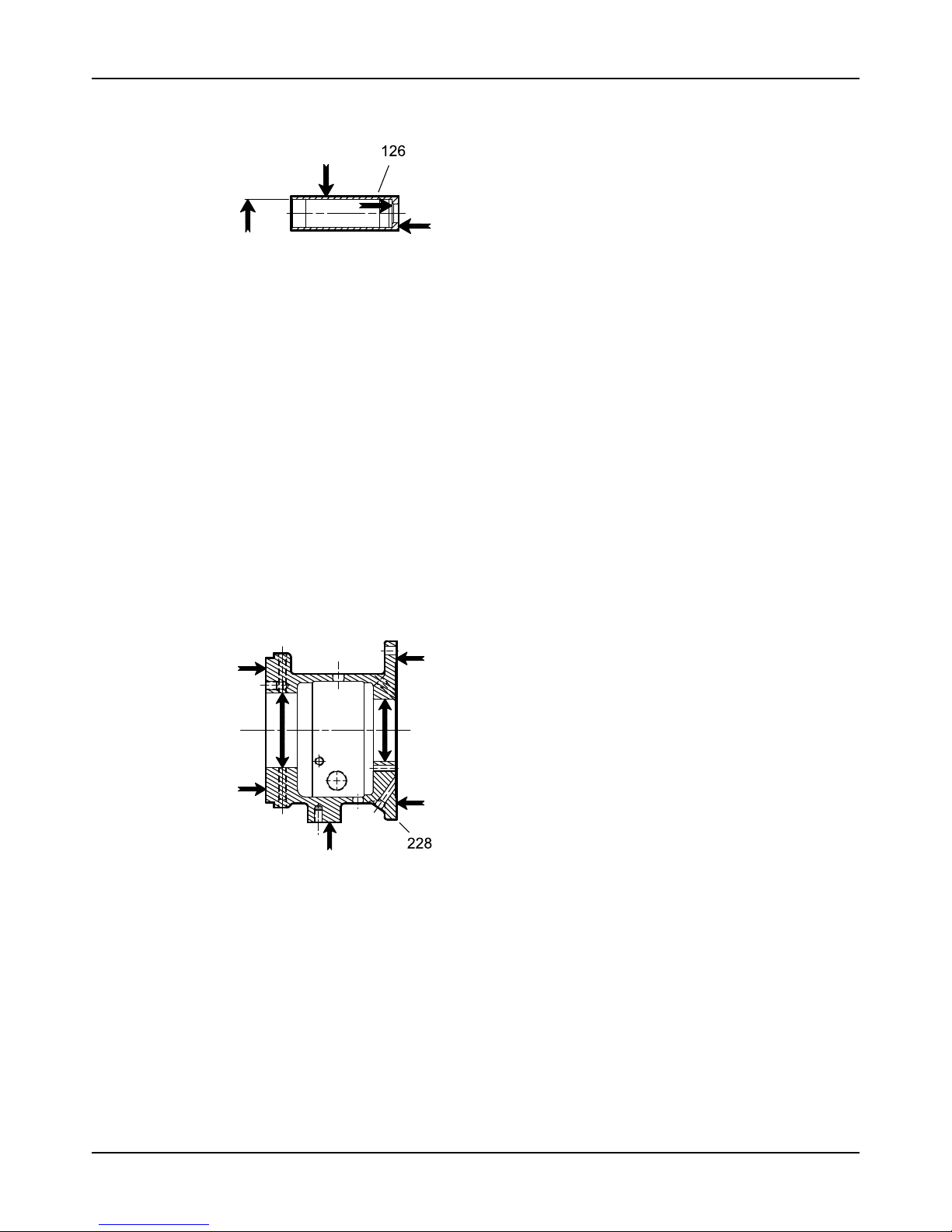
Maintenance
Model 3196 i-FRAME Installation, Operation, and Maintenance Manual 97
Shaft and sleeve check
Figure 80: Shaft and sleeve check
• Check the shaft and sleeve (126) surface for grooves and pitting.
• Replace the shaft and sleeve if any grooves or pits are found.
Bearing-frame inspection
Checklist
Check the bearing frame for these conditions:
• Visually inspect the bearing frame and frame foot for cracks.
• Check the inside surfaces of the frame for rust, scale, or debris. Remove all loose and
foreign material.
• Make sure that all lubrication passages are clear.
• If the frame has been exposed to pumped fluid, inspect the frame for corrosion or pitting.
• Inspect the inboard-bearing bores.
If any bores are outside the measurements in the Bearing fits and tolerances table, replace
the bearing frame.
Surface inspection locations
This figure shows the areas to inspect for wear on the bearing frame outside surface.
Figure 81: Outside surface inspection locations
Page 100
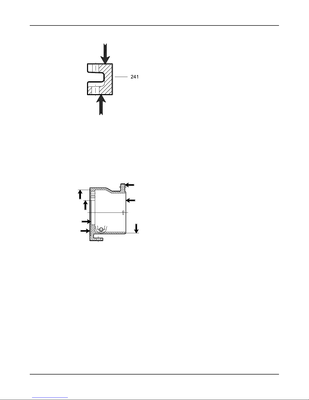
Maintenance
Model 3196 i-FRAME Installation, Operation, and Maintenance Manual98
This figure shows the areas to inspect for wear on the bearing frame inside surface.
Figure 82: Inside surface inspection locations
C-face adapter inspection
Checklist
• Visually inspect the C-face adapter (340) for cracks.
• Check all surfaces for rust, scale, or debris and remove all loose and foreign material.
• Check for corrosion or pitting.
This figure shows the areas to inspect for cracks on the C-face adapter.
Figure 83: C-face adapter inspection locations
Seal chamber and stuffing box cover inspection
Checklist
Perform these checks when you inspect the seal chamber and stuffing box cover:
• Make sure that these surfaces are clean:
• Seal chamber and stuffing box cover
• Dynamic-seal backplate gasket
• Mounting
• Make sure there is no pitting or wear greater than 3.2 mm | 1/8 in. deep.
Replace the seal chamber and stuffing box cover if pitting or wear exceeds this
measurement.
• Inspect the machined surfaces and mating faces noted in the figures.
These images point to the areas to inspect:
 Loading...