

Goulds Pumps 3196 i-FRAME Installation, Operation And Maintenance Manual

Installation, Operation,
and Maintenance Manual
Model 3196 i-FRAME


Table of Contents
Model 3196 i-FRAME Installation, Operation, and Maintenance Manual 1
Table of Contents
Introduction and Safety ..........................................................................................................5
Introduction .............................................................................................................................5
Safety ...................................................................................................................................... 6
Safety terminology and symbols ........................................................................................... 6
Environmental safety ............................................................................................................ 7
User safety ........................................................................................................................... 8
Ex-approved products .......................................................................................................... 9
Product approval standards .................................................................................................. 10
Product warranty ................................................................................................................... 11
Transportation and Storage .................................................................................................12
Inspect the delivery ............................................................................................................... 12
Inspect the package ........................................................................................................... 12
Inspect the unit ................................................................................................................... 12
Transportation guidelines ...................................................................................................... 12
Pump handling ................................................................................................................... 12
Lifting methods ................................................................................................................... 12
Storage guidelines ................................................................................................................ 15
Pump storage requirements ............................................................................................... 15
Frostproofing ...................................................................................................................... 15
Product Description .............................................................................................................. 16
General description 3196 ......................................................................................................16
Part description 3196 .......................................................................................................... 17
General description i-ALERT®Condition Monitor .................................................................. 18
Nameplate information .......................................................................................................... 20
Installation ............................................................................................................................. 23
Preinstallation ....................................................................................................................... 23
Pump location guidelines .................................................................................................... 23
Foundation requirements ................................................................................................... 24
Baseplate-mounting procedures ...........................................................................................24
Prepare the baseplate for mounting ................................................................................... 24
Install the baseplate using shims or wedges ...................................................................... 25
Install the baseplate using jackscrews ................................................................................ 26
Install the baseplate using spring mounting ........................................................................ 28
Install the baseplate using stilt mounting ............................................................................ 29
Baseplate-leveling worksheet ............................................................................................. 31
Install the pump, driver, and coupling .................................................................................... 32
Pump-to-driver alignment ...................................................................................................... 32
Alignment checks ............................................................................................................... 32
Permitted indicator values for alignment checks ................................................................ 33
Alignment measurement guidelines ................................................................................... 33
Attach the dial indicators for alignment ...............................................................................34
Pump-to-driver alignment instructions ................................................................................ 34
C-face adapter .................................................................................................................... 37
Grout the baseplate .............................................................................................................. 37
Piping checklists ................................................................................................................... 39
General piping checklist ..................................................................................................... 39
Suction-piping checklist ...................................................................................................... 40
Discharge piping checklist .................................................................................................. 42

Table of Contents
Model 3196 i-FRAME Installation, Operation, and Maintenance Manual2
Commissioning, Startup, Operation, and Shutdown ......................................................... 44
Preparation for startup .......................................................................................................... 44
Remove the coupling guard .................................................................................................. 45
Check the rotation - Frame Mounted ..................................................................................... 47
Impeller-clearance check ......................................................................................................47
Impeller clearances (3196 and HT 3196) ........................................................................... 48
Impeller-clearance setting ..................................................................................................... 48
Set the impeller clearance - dial indicator method (all except CV 3196) .............................48
Set the impeller clearance - feeler gauge method (all except CV 3196) ............................. 49
Couple the pump and driver .................................................................................................. 50
Install the coupling guard .................................................................................................... 51
Bearing lubrication .............................................................................................................. 55
Shaft-sealing options ............................................................................................................ 57
Mechanical seal options ..................................................................................................... 57
Connection of sealing liquid for mechanical seals .............................................................. 57
Packed stuffing box option ................................................................................................. 58
Connection of sealing liquid for a packed stuffing box ........................................................ 58
Dynamic-seal option ........................................................................................................... 58
Set an elastomeric face seal ............................................................................................... 59
Prime the pump with the suction supply above the pump ..................................................... 59
Prime the pump with the suction supply below the pump ...................................................... 60
Other methods of priming the pump ...................................................................................... 61
Start the pump ...................................................................................................................... 61
Activate the i-ALERT®Condition Monitor .............................................................................. 62
i-ALERT®Condition Monitor routine operation ...................................................................... 63
Pump operation precautions ................................................................................................. 63
Shut down the pump ............................................................................................................. 64
Deactivate the i-ALERT®Condition Monitor ..........................................................................64
Reset the i-ALERT®Condition Monitor ................................................................................. 65
Make the final alignment of the pump and driver ................................................................... 66
Maintenance ........................................................................................................................... 67
Maintenance schedule ..........................................................................................................67
Bearing maintenance ............................................................................................................68
Lubricating-oil requirements ............................................................................................... 68
Regrease the grease-lubricated bearings .......................................................................... 69
Lubricate the bearings after a shutdown period .................................................................. 70
Mechanical-seal maintenance .............................................................................................. 70
Packed stuffing-box maintenance .........................................................................................71
Dynamic-seal maintenance ................................................................................................... 72
Disassembly precautions ......................................................................................................72
Tools required .......................................................................................................................73
Drain the pump ..................................................................................................................... 73
Remove the coupling ............................................................................................................ 73
Remove the back pull-out assembly ..................................................................................... 74
Remove the coupling hub ..................................................................................................... 76
Impeller removal ................................................................................................................... 76
Remove the impeller (STi, MTi, and LTi) ............................................................................ 76
Remove the impeller (XLT-i, and i17) ................................................................................. 77
Seal-chamber cover removal ................................................................................................ 79
Remove the seal-chamber cover (3196, CV 3196, HT 3196, LF 3196, 3796) ....................... 79
Remove the stuffing-box cover (3196, CV 3196, HT 3196, LF 3196, 3796) .......................... 80
Remove the dynamic seal ..................................................................................................... 81
Remove the frame adapter (MTi, LTi, XLT-i, i17) .................................................................. 82
Remove the inboard labyrinth oil seal ................................................................................... 83
Disassemble the power end (STi, MTi) ................................................................................. 83
Disassemble the power end (STi and MTi with duplex bearings) .......................................... 85

Table of Contents
Model 3196 i-FRAME Installation, Operation, and Maintenance Manual 3
Disassemble the power end (LTi) ......................................................................................... 87
Disassemble the power end (XLT-i and i17) ......................................................................... 89
Disassemble the power end (XLT-i and i17 with duplex bearings) ........................................ 91
Disassemble the bearing frame ............................................................................................ 92
Guidelines for i-ALERT®Condition Monitor disposal ............................................................. 93
Disassemble the C-face adapter ........................................................................................... 93
Pre-assembly inspections .....................................................................................................94
Replacement guidelines ..................................................................................................... 94
Shaft and sleeve replacement guidelines ...........................................................................96
Bearing-frame inspection ................................................................................................... 97
C-face adapter inspection ................................................................................................... 98
Seal chamber and stuffing box cover inspection ................................................................ 98
Bearings inspection .......................................................................................................... 100
Bearing-housing inspection .............................................................................................. 100
Bearing fits and tolerances ...............................................................................................102
Assemble the rotating element and the bearing frame (STi and MTi) ................................. 102
Assemble the rotating element and the bearing frame (STi and MTi with duplex
bearings) ............................................................................................................................. 105
Assemble the rotating element and the bearing frame (LTi) ............................................... 108
Assemble the rotating element and the bearing frame (XLT-i and i17) ............................... 111
Assemble the rotating element and the bearing frame (XLT-i and i17 with duplex
bearings) ............................................................................................................................. 114
Assemble the frame ............................................................................................................ 118
INPRO labyrinth oil seal description .................................................................................... 121
Assemble the INPRO labyrinth oil seal ............................................................................... 122
Assemble the C-face adapter .............................................................................................. 122
Shaft sealing ....................................................................................................................... 123
Seal the shaft with a dynamic seal .................................................................................... 123
Seal the shaft with a packed stuffing box .......................................................................... 124
Seal the shaft with a cartridge mechanical seal ................................................................ 125
Seal the shaft with a conventional inside-component mechanical seal ............................ 126
Seal the shaft with a conventional outside-component mechanical seal .......................... 127
Install the impeller ............................................................................................................... 130
Attach the i-ALERT®Condition Monitor to the pump ...........................................................131
Post-assembly checks ........................................................................................................ 132
Install the back pull-out assembly (except HT 3196) ........................................................... 132
Bolt torque values ............................................................................................................... 135
Shaft-end play ..................................................................................................................... 136
Bearing types ......................................................................................................................136
Spare parts ......................................................................................................................... 136
3196 interchangeability .......................................................................................................137
Frame lubrication conversion ..............................................................................................137
Convert from greased-for-life or regreaseable to oil-lubricated bearings ............................ 138
Conversion from flood-oil to pure-oil mist ............................................................................ 139
Convert from flood oil to regreaseable ................................................................................ 139
Troubleshooting .................................................................................................................. 140
Operation troubleshooting ................................................................................................... 140
Alignment troubleshooting .................................................................................................. 141
Assembly troubleshooting ................................................................................................... 141
i-ALERT®Condition Monitor troubleshooting ...................................................................... 141
Parts Listings and Cross-Sectionals .................................................................................142
Parts list .............................................................................................................................. 142
Certification: CE or CE ATEX ............................................................................................. 151
Certificates of conformance ................................................................................................ 151

Table of Contents
Model 3196 i-FRAME Installation, Operation, and Maintenance Manual4
Other Relevant Documentation or Manuals ...................................................................... 157
Local ITT Contacts .............................................................................................................. 158
Regional offices .................................................................................................................. 158

Introduction and Safety
Model 3196 i-FRAME Installation, Operation, and Maintenance Manual 5
Introduction and Safety
Introduction
Purpose of this manual
The purpose of this manual is to provide necessary information for:
• Installation
• Operation
• Maintenance
CAUTION:
Failure to observe the instructions contained in this manual could result in personal injury and
property damage, and may void the warranty. Read this manual carefully before installing and
using the product.
NOTICE:
Save this manual for future reference and keep it readily available.
Requesting other information
Special versions can be supplied with supplementary instruction leaflets. See the sales
contract for any modifications or special version characteristics. For instructions, situations, or
events that are not considered in this manual or in the sales documents, please contact the
nearest ITT representative.
Always specify the exact product type and identification code when requesting technical
information or spare parts.
Introduction and Safety
Model 3196 i-FRAME Installation, Operation, and Maintenance Manual6
Safety
WARNING:
• The operator must be aware of the pumpage and take appropriate safety precautions to
prevent physical injury.
• Risk of serious injury or death. If any pressure-containing device is over-pressurized, it can
explode, rupture, or discharge its contents. It is critical to take all necessary measures to
avoid over-pressurization.
• Risk of death, serious personal injury, and property damage. Installing, operating, or
maintaining the unit using any method not prescribed in this manual is prohibited.
Prohibited methods include any modification to the equipment or use of parts not provided
by ITT. If there is any uncertainty regarding the appropriate use of the equipment, please
contact an ITT representative before proceeding.
• Risk of serious personal injury. Applying heat to impellers, propellers, or their retaining
devices can cause trapped liquid to rapidly expand and result in a violent explosion. This
manual clearly identifies accepted methods for disassembling units. These methods must
be adhered to. Never apply heat to aid in their removal unless explicitly stated in this
manual.
• If the pump or motor is damaged or leaking, electric shock, fire, explosion, liberation of
toxic fumes, physical harm, or environmental damage may result. Do not operate the unit
until the problem has been corrected or repaired.
• Risk of serious personal injury or property damage. Dry running may cause rotating parts
within the pump to seize to non-moving parts. Do not run dry.
• Risk of death, serious personal injury, and property damage. Heat and pressure buildup
can cause explosion, rupture, and discharge of pumpage. Never operate the pump with
suction and/or discharge valves closed.
• Running a pump without safety devices exposes operators to risk of serious personal
injury or death. Never operate a unit unless appropriate safety devices (guards, etc.) are
properly installed. See specific information about safety devices in other sections of this
manual.
CAUTION:
Risk of injury and/or property damage. Operating a pump in an inappropriate application can
cause over pressurization, overheating, and/or unstable operation. Do not change the service
application without the approval of an authorized ITT representative.
Safety terminology and symbols
About safety messages
It is extremely important that you read, understand, and follow the safety messages and
regulations carefully before handling the product. They are published to help prevent these
hazards:
• Personal accidents and health problems
• Damage to the product
• Product malfunction
Hazard levels
Hazard level Indication
DANGER:
A hazardous situation which, if not avoided, will
result in death or serious injury
Introduction and Safety
Model 3196 i-FRAME Installation, Operation, and Maintenance Manual 7
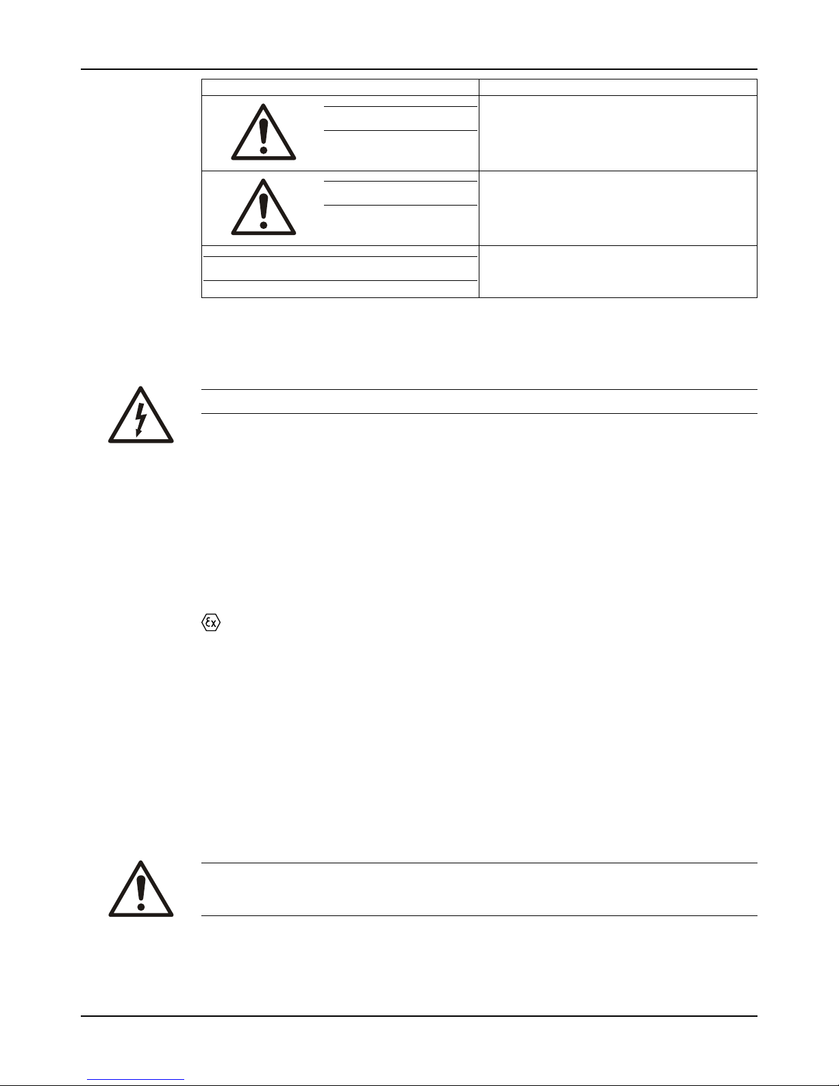
Hazard level Indication
WARNING:
A hazardous situation which, if not avoided,
could result in death or serious injury
CAUTION:
A hazardous situation which, if not avoided,
could result in minor or moderate injury
NOTICE:
• A potential situation which, if not avoided,
could result in undesirable conditions
• A practice not related to personal injury
Hazard categories
Hazard categories can either fall under hazard levels or let specific symbols replace the
ordinary hazard level symbols.
Electrical hazards are indicated by the following specific symbol:
Electrical Hazard:
These are examples of other categories that can occur. They fall under the ordinary hazard
levels and may use complementing symbols:
• Crush hazard
• Cutting hazard
• Arc flash hazard
The Ex symbol
The Ex symbol indicates safety regulations for Ex-approved products when used in
atmospheres that are potentially explosive or flammable.
Environmental safety
The work area
Always keep the station clean to avoid and/or discover emissions.
Waste and emissions regulations
Observe these safety regulations regarding waste and emissions:
• Appropriately dispose of all waste.
• Handle and dispose of the processed liquid in compliance with applicable environmental
regulations.
• Clean up all spills in accordance with safety and environmental procedures.
• Report all environmental emissions to the appropriate authorities.
WARNING:
If the product has been contaminated in any way, such as from toxic chemicals or nuclear
radiation, do NOT send the product to ITT unless it has been properly decontaminated.
Electrical installation
For electrical installation recycling requirements, consult your local electric utility.

Introduction and Safety
Model 3196 i-FRAME Installation, Operation, and Maintenance Manual8
Recycling guidelines
Always follow local laws and regulations regarding recycling.
User safety
General safety rules
These safety rules apply:
• Always keep the work area clean.
• Pay attention to the risks presented by gas and vapors in the work area.
• Avoid all electrical dangers. Pay attention to the risks of electric shock or arc flash hazards.
• Always bear in mind the risk of drowning, electrical accidents, and burn injuries.
Safety equipment
Use safety equipment according to the company regulations. Use this safety equipment within
the work area:
• Helmet
• Safety goggles, preferably with side shields
• Protective shoes
• Protective gloves
• Gas mask
• Hearing protection
• First-aid kit
• Safety devices
Electrical connections
Electrical connections must be made by certified electricians in compliance with all international, national, state, and local regulations. For more information about requirements, see sections
dealing specifically with electrical connections.
Precautions before work
Observe these safety precautions before you work with the product or are in connection with
the product:
• Provide a suitable barrier around the work area, for example, a guard rail.
• Make sure that all safety guards are in place and secure.
• Make sure that you have a clear path of retreat.
• Make sure that the product cannot roll or fall over and injure people or damage property.
• Make sure that the lifting equipment is in good condition.
• Use a lifting harness, a safety line, and a breathing device as required.
• Allow all system and pump components to cool before you handle them.
• Make sure that the product has been thoroughly cleaned.
• Disconnect and lock out power before you service the pump.
• Check the explosion risk before you weld or use electric hand tools.
Precautions during work
Observe these safety precautions when you work with the product or are in connection with the
product:
CAUTION:
Failure to observe the instructions contained in this manual could result in personal injury and
property damage, and may void the warranty. Read this manual carefully before installing and
using the product.

Introduction and Safety
Model 3196 i-FRAME Installation, Operation, and Maintenance Manual 9
• Never work alone.
• Always wear protective clothing and hand protection.
• Stay clear of suspended loads.
• Always lift the product by its lifting device.
• Beware of the risk of a sudden start if the product is used with an automatic level control.
• Beware of the starting jerk, which can be powerful.
• Rinse the components in water after you disassemble the pump.
• Do not exceed the maximum working pressure of the pump.
• Do not open any vent or drain valve or remove any plugs while the system is pressurized.
Make sure that the pump is isolated from the system and that pressure is relieved before
you disassemble the pump, remove plugs, or disconnect piping.
• Never operate a pump without a properly installed coupling guard.
• The coupling guard used in an ATEX classified environment must be constructed from
a non-sparking material.
Hazardous liquids
The product is designed for use in liquids that can be hazardous to your health. Observe these
rules when you work with the product:
• Make sure that all personnel who work with biologically hazardous liquids are vaccinated
against diseases to which they may be exposed.
• Observe strict personal cleanliness.
• A small amount of liquid will be present in certain areas like the seal chamber.
Wash the skin and eyes
1. Follow these procedures for chemicals or hazardous fluids that have come into contact with
your eyes or your skin:
Condition Action
Chemicals or hazardous
fluids in eyes
1. Hold your eyelids apart forcibly with your fingers.
2. Rinse the eyes with eyewash or running water for at least 15 minutes.
3. Seek medical attention.
Chemicals or hazardous
fluids on skin
1. Remove contaminated clothing.
2. Wash the skin with soap and water for at least 1 minute.
3. Seek medical attention, if necessary.
Ex-approved products
Follow these special handling instructions if you have an Ex-approved unit.
Personnel requirements
These are the personnel requirements for Ex-approved products in potentially explosive
atmospheres:
• All work on the product must be carried out by certified electricians and ITT-authorized
mechanics. Special rules apply to installations in explosive atmospheres.
• All users must know about the risks of electric current and the chemical and physical
characteristics of the gas, the vapor, or both present in hazardous areas.
• Any maintenance for Ex-approved products must conform to international and national
standards (for example, IEC/EN 60079-17).
ITT disclaims all responsibility for work done by untrained and unauthorized personnel.
Product and product handling requirements
These are the product and product handling requirements for Ex-approved products in
potentially explosive atmospheres:
• Only use the product in accordance with the approved motor data.
Introduction and Safety
Model 3196 i-FRAME Installation, Operation, and Maintenance Manual10
• The Ex-approved product must never run dry during normal operation. Dry running during
service and inspection is only permitted outside the classified area.
• Before you start work on the product, make sure that the product and the control panel are
isolated from the power supply and the control circuit, so they cannot be energized.
• Do not open the product while it is energized or in an explosive gas atmosphere.
• Make sure that thermal contacts are connected to a protection circuit according to the
approval classification of the product, and that they are in use.
• Intrinsically safe circuits are normally required for the automatic level-control system by the
level regulator if mounted in zone 0.
• The yield stress of fasteners must be in accordance with the approval drawing and the
product specification.
• Do not modify the equipment without approval from an authorized ITT representative.
• Only use parts that are provided by an authorized ITT representative.
Product approval standards
Regular standards
WARNING:
Use of equipment unsuitable for the environment can pose risks of ignition and/or explosion.
Ensure that the code classifications on the pump are compatible with the specific environment
in which the equipment is to be installed. If they are not compatible, do not operate the
equipment and contact an ITT representative before proceeding.
All standard products are approved according to CSA standards in Canada and UL standards
in USA. The drive unit degree of protection follows IP68. See the nameplate for maximum
submersion, according to standard IEC 60529.
All electrical ratings and performance of the motors comply with IEC 600341.
Explosion-proofing standards
All explosion-proof products for use in explosive atmospheres are designed in compliance with
one or more of the following approvals:
• EN, ATEX Directive 94/9/EC
• FM According to NEC
• Class 1 Div 1 Groups “C”, and “D”
• Class 2 Div 1 Groups “E”, “F”, and “G”
• Class 3 Div 1 Hazardous Locations
ATEX/IECEx:
• Group: IIC
• Category: Ex ia
• Temperature Class: T4 (for ambients up to 100ºC)
• ATEX Marking: Ex II 1 G
CSA certification
Intrinsically safe for:
• Class I, Div. 1, Groups A, B, C, D
• Class II, Div. 1, Groups E, F, G

Introduction and Safety
Model 3196 i-FRAME Installation, Operation, and Maintenance Manual 11
• Class III
• Certified to Canadian and US requirements
Product warranty
Coverage
ITT undertakes to remedy faults in products from ITT under these conditions:
• The faults are due to defects in design, materials, or workmanship.
• The faults are reported to an ITT representative within the warranty period.
• The product is used only under the conditions described in this manual.
• The monitoring equipment incorporated in the product is correctly connected and in use.
• All service and repair work is done by ITT-authorized personnel.
• Genuine ITT parts are used.
• Only Ex-approved spare parts and accessories authorized by ITT are used in Ex-approved
products.
Limitations
The warranty does not cover faults caused by these situations:
• Deficient maintenance
• Improper installation
• Modifications or changes to the product and installation made without consulting ITT
• Incorrectly executed repair work
• Normal wear and tear
ITT assumes no liability for these situations:
• Bodily injuries
• Material damages
• Economic losses
Warranty claim
ITT products are high-quality products with expected reliable operation and long life. However,
should the need arise for a warranty claim, then contact your ITT representative.
Transportation and Storage
Model 3196 i-FRAME Installation, Operation, and Maintenance Manual12
Transportation and Storage
Inspect the delivery
Inspect the package
1. Inspect the package for damaged or missing items upon delivery.
2. Note any damaged or missing items on the receipt and freight bill.
3. File a claim with the shipping company if anything is out of order.
If the product has been picked up at a distributor, make a claim directly to the distributor.
Inspect the unit
1. Remove packing materials from the product.
Dispose of all packing materials in accordance with local regulations.
2. Inspect the product to determine if any parts have been damaged or are missing.
3. If applicable, unfasten the product by removing any screws, bolts, or straps.
For your personal safety, be careful when you handle nails and straps.
4. Contact your sales representative if anything is out of order.
Transportation guidelines
Pump handling
WARNING:
Dropping, rolling or tipping units, or applying other shock loads, can cause property damage
and personal injury. Ensure that the unit is properly supported and secure during lifting and
handling.
CAUTION:
Risk of injury or equipment damage from use of inadequate lifting devices. Ensure lifting
devices (such as chains, straps, forklifts, cranes, etc.) are rated to sufficient capacity.
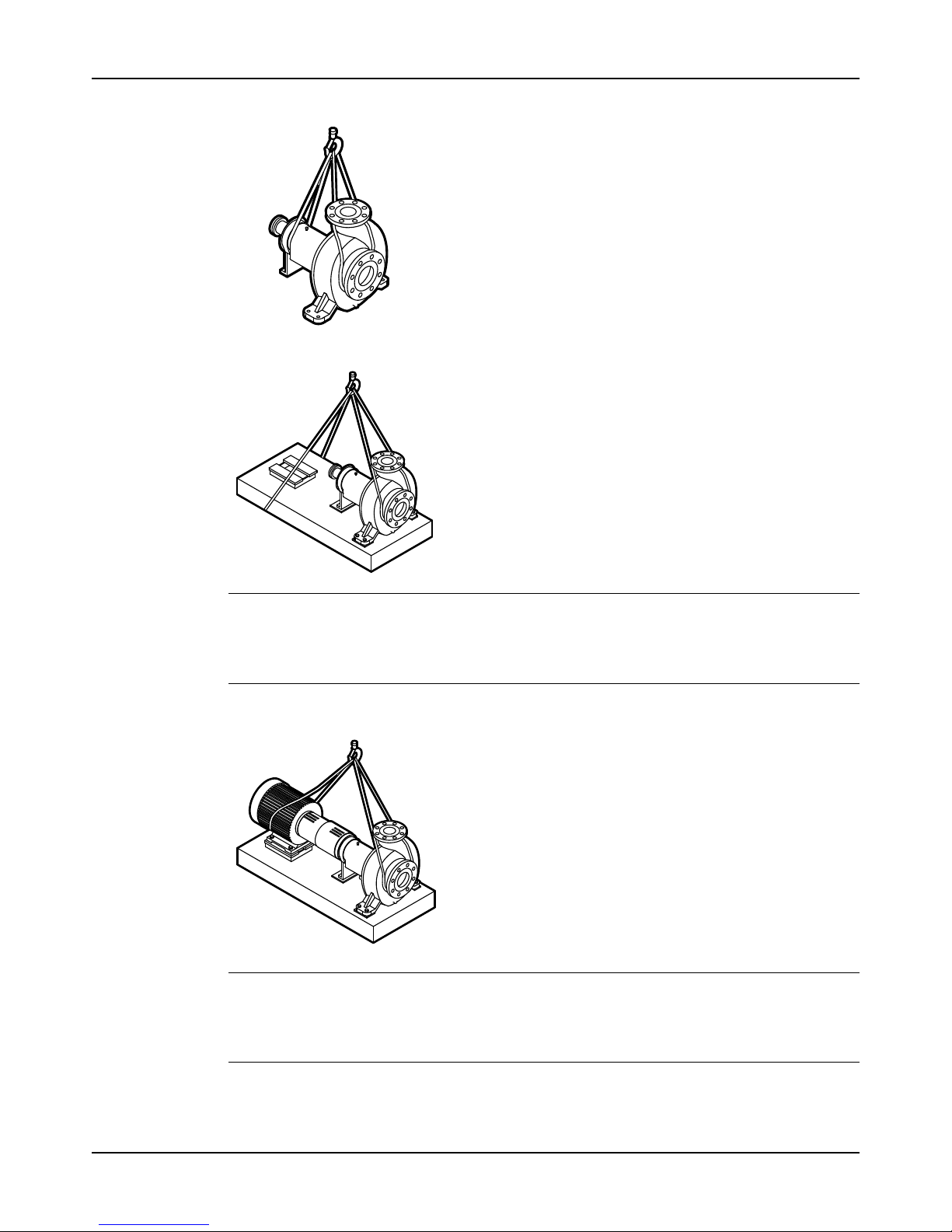
Lifting methods
WARNING:
• Risk of serious personal injury or equipment damage. Proper lifting practices are critical to
safe transport of heavy equipment. Ensure that practices used are in compliance with all
applicable regulations and standards.
• Safe lifting points are specifically identified in this manual. It is critical to lift the equipment
only at these points. Integral lifting eyes or eye bolts on pump and motor components are
intended for use in lifting the individual components only.
• Lifting and handling heavy equipment poses a crush hazard. Use caution during lifting and
handling and wear appropriate Personal Protective Equipment (PPE, such as steel-toed
shoes, gloves, etc.) at all times. Seek assistance if necessary.
Table 1: Methods
Pump type Lifting method
A bare pump without lifting handles
Use a suitable sling attached properly to solid points like the casing,
the flanges, or the frames.
A bare pump with lifting handles Liftthepumpbythehandles.
A base-mounted pump Use slings under the pump casing and the drive unit, or under the base
rails.
Transportation and Storage
Model 3196 i-FRAME Installation, Operation, and Maintenance Manual 13
Examples
Figure 1: Example of a proper lifting method
NOTICE:
Do not use this method to lift a Polyshield ANSI Combo with the pump and motor mounted.
These items are not designed to handle the heavy weight of the Polyshield system. Doing so
may result in equipment damage.
Figure 2: Example of a proper lifting method
NOTICE:
Do not use this method to lift a Polyshield ANSI Combo with the pump and motor mounted.
These items are not designed to handle the heavy weight of the Polyshield system. Doing so
may result in equipment damage.
Figure 3: Example of a proper lifting method
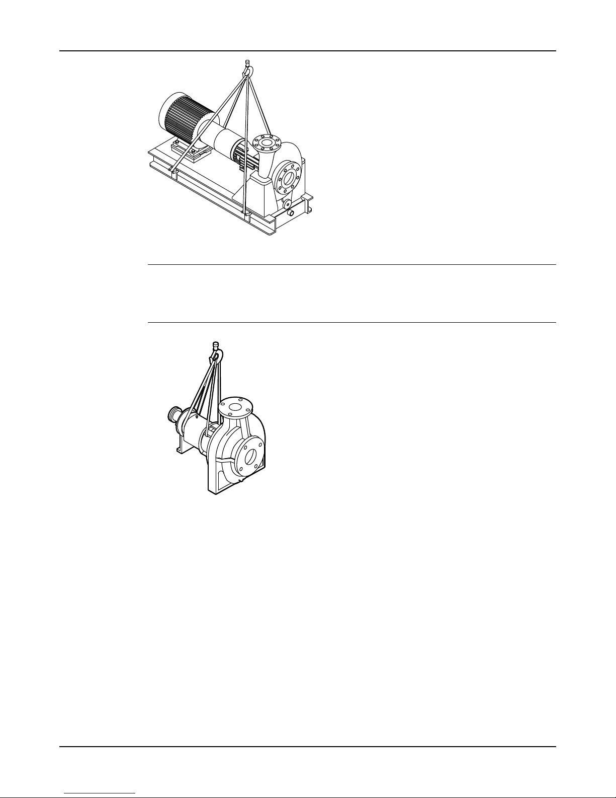
Transportation and Storage
Model 3196 i-FRAME Installation, Operation, and Maintenance Manual14
Figure 4: Example of a proper lifting method
NOTICE:
When lifting a unit for which a strap cannot be secured at the suction flange, secure the strap
through the frame/frame adapter. Securing at the frame adapter will prevent slipping of the
strap and possible equipment damage.
Figure 5: Example of a proper lifting method with a strap secured around the frame adapter
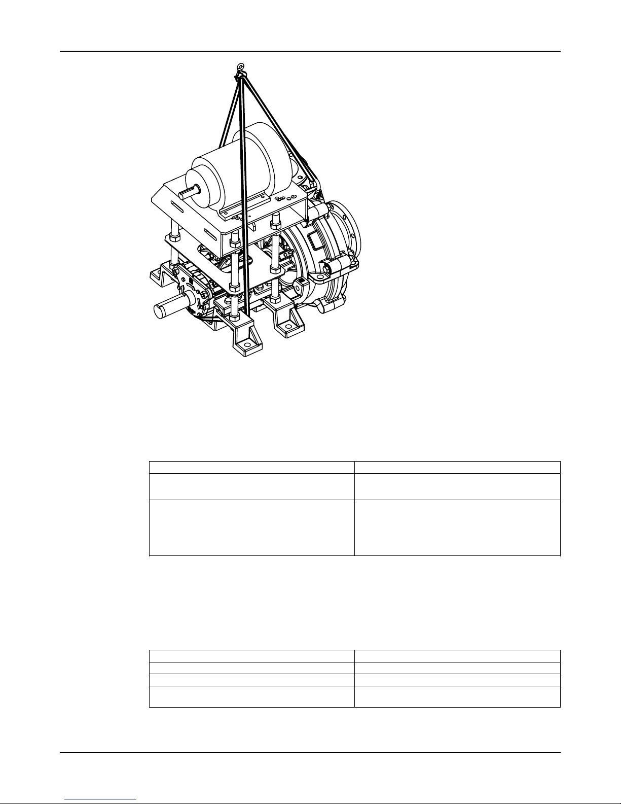
Transportation and Storage
Model 3196 i-FRAME Installation, Operation, and Maintenance Manual 15
Figure 6: Example of offset overhead motor mount pump proper lifting method
Storage guidelines
Pump storage requirements
Storage requirements depend on the amount of time that you store the unit. The normal
packaging is designed only to protect the unit during shipping.
Length of time in storage Storage requirements
Upon receipt/short-term (less than six months)
• Store in a covered and dry location.
• Store the unit free from dirt and vibrations.
Long-term (more than six months)
• Store in a covered and dry location.
• Store the unit free from heat, dirt, and vibrations.
• Rotate the shaft by hand several times at least
every three months.
Treat bearing and machined surfaces so that they are well preserved. Refer to drive unit and
coupling manufacturers for their long-term storage procedures.
You can purchase long-term storage treatment with the initial unit order or you can purchase it
and apply it after the units are already in the field. Contact your local ITT sales representative.
Frostproofing
Table 2: Situations when the pump is or is not frostproof
Situation Condition
Operating The pump is frostproof.
Immersed in a liquid The pump is frostproof.
Lifted out of a liquid into a temperature below
freezing
The impeller might freeze.

Product Description
Model 3196 i-FRAME Installation, Operation, and Maintenance Manual16
Product Description
General description 3196
The 3196 is a horizontal overhung, open impeller, centrifugal pump. This pump is ANSI B73.1
compliant.
The model is based on 5 power ends and 29 hydraulic sizes.
Figure 7: 3196 pump
This table shows the number of hydraulic sizes available for each drive-unit size group.
Drive-unit size group Number of hydraulic sizes
STi 5
MTi 15
LTi 15
XLT-i 5
i-17 4
WARNING:
Use of equipment unsuitable for the environment can pose risks of ignition and/or explosion.
Ensure that the code classifications on the pump are compatible with the specific environment
in which the equipment is to be installed. If they are not compatible, do not operate the
equipment and contact an ITT representative before proceeding.
Product Description
Model 3196 i-FRAME Installation, Operation, and Maintenance Manual 17
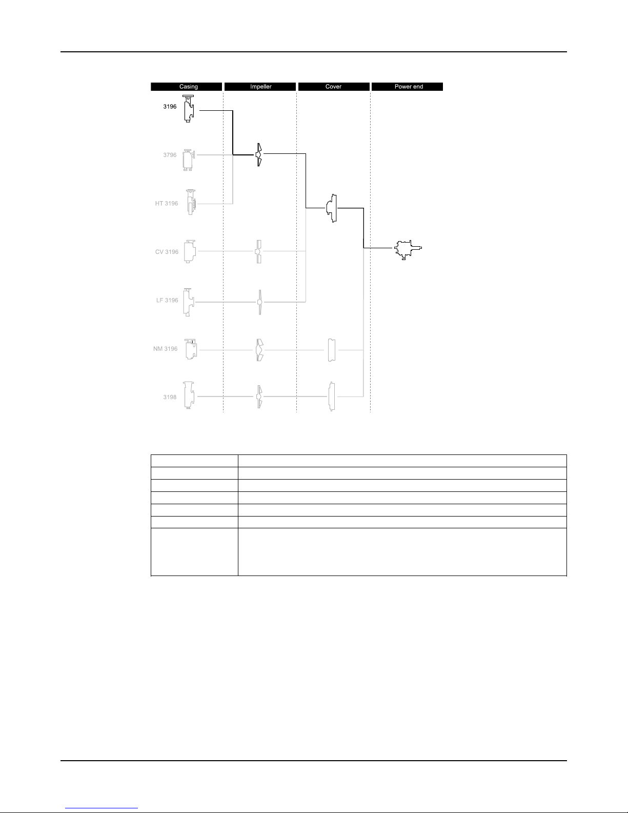
Part description 3196
Figure 8: 3196 part description
Table 3: Casing
This table describes the pump casing parts.
Part Description
Discharge Top-centerline
Casing ventilation Self venting
Gasket Fully confined
Mounting method Integral foot support for maximum resistance to misalignment due to piping loads.
Standard flange ANSI flat-faced serrated flange
Optional flanges One of the following flanges can be used:
• ANSI class 150 raised-face serrated flange
• ANSI class 300 flat-face serrated flange
• ANSI class 300 raised-face serrated flange
Impeller
The impeller is
• fully open
• threaded onto the shaft
The threads are sealed from the pumped liquid by a PTFE O-ring for the 3196.
Cover
Standard
• Stuffing Box cover designed for packing or a mechanical seal
• BigBore or TaperBore® PLUS seal chambers designed for improved performance of
mechanical seals

Product Description
Model 3196 i-FRAME Installation, Operation, and Maintenance Manual18
Optional sealing design
• a dynamic seal is available which uses a repeller to pump liquid out of the stuffing box
while the pump operates. A static seal prevents leakage when the pump is shut down.
Table 4: Power end
This table describes the main parts of the power end.
Part Description
Frame adapter The ductile iron frame adapter has
• a machined rabbet fit to the seal chamber/ stuffing box cover
• a precision dowel pin fit to the bearing frame.
Power end
• Flood-oil lubrication is standard.
• Oil-mist, regreasable and greased-for-life options are available.
• The oil level is checked through a sight glass.
• The power end is sealed with labyrinth seals.
• The power end is made in the following sizes:
• STi
• MTi
• LTi
• XLT-i
• i-17
Shaft The shaft is available with or without a sleeve.
Bearings The inboard bearing
• carries only radial loads.
• is free to float axially in the frame.
• is a single-row deep-groove ball bearing
The outboard bearing
• is shouldered and locked to the shaft and housing to enable it to carry radial
and thrust loads.
• is a double-row angular-contact bearing, except for the LTi which uses a pair
of single-row angular-contact ball bearings mounted back-to-back.
General description i-ALERT®Condition Monitor
Description
The i-ALERT®2 Condition Monitor is a compact, battery-operated monitoring device that
continuously measures the vibration and temperature of the pump power end. The condition
monitor uses blinking red LEDs to alert the pump operator when the pump exceeds pre-set
vibration and temperature limits. This allows the pump operator to make changes to the
process or the pump before a catastrophic failure occurs. The condition monitor is also
equipped with a single green LED to indicate when it is operational and has sufficient battery
life. (i-ALERT®2) Bluetooth Equipment Health Monitor option available. The i-ALERT®2 monitor
allows customers to identify potential problems before they become costly failures. It tracks
vibration, temperature and run-time hours and wirelessly syncs the data with a smart phone or
tablet the i-ALERT®2 mobile app. More information available on http://www.ittproservices.com/
aftermarket-products/monitoring/i-alert2/i-ALERT2.com).
Software License Agreement
BY USING THE i-ALERT®2 CONDITION MONITOR, YOU AGREE TO BE BOUND BY THE
TERMS AND CONDITIONS OF THE FOLLOWING LICENSE AGREEMENT. PLEASE READ
THIS AGREEMENT CAREFULLY.
ITT Corporation and its subsidiaries, affiliates, either directly, or through its authorized
sublicensees ("ITT") grants you a limited, non-exclusive license to use the software embedded
in this device ("Software") in binary executable form in the normal operation of the i-ALERT®2
condition monitor for monitoring the condition of an Goulds Pump Inc. model. Title, ownership
rights, and intellectual property rights in and to the Software remain in ITT or its third-party

Product Description
Model 3196 i-FRAME Installation, Operation, and Maintenance Manual 19
providers. You agree that this license agreement does not need to be signed for it to take
effect.
You acknowledge that this Software is the property of ITT and is protected under United States
of America copyright laws and international copyright treaties. You further acknowledge that
the structure, organization, and code of the Software are valuable trade secrets of ITT and/or
its third-party providers and that the Software in source code form remains a valuable trade
secret of ITT. You agree not to decompile, disassemble, modify, reverse assemble, reverse
engineer, or reduce to human readable form the Software or any part thereof or create any
derivative works based on the Software. You agree not to export or re-export the Software to
any country in violation of the export control laws of the United States of America.
Alarm mode
The condition monitor enters alarm mode when either vibration or temperature limits are
exceeded over two consecutive readings within a ten minute period. Alarm mode is indicated
with two red flashing LEDs within two second intervals.
Temperature and vibration limits
Variable Limit
Temperature 91°C | 195°F
Vibration 100%increaseoverthebaselinelevel
Battery life
The i-ALERT®2 Condition Monitor battery is not replaceable. You must replace the entire
unit once the battery runs out of power.
The battery life is not covered as part of the standard pump warranty.
This table shows the average condition monitor battery life under normal and alarm-mode operating
conditions.
Condition monitor operational state Battery life
Normal operating and environmental conditions Three to five years
Alarm mode One year

Product Description
Model 3196 i-FRAME Installation, Operation, and Maintenance Manual20
Nameplate information
Important information for ordering
Every pump has nameplates that provide information about the pump. The nameplates are
located on the casing and the bearing frame.
When you order spare parts, identify this pump information:
• Model
• Size
• Serial number
• Item numbers of the required parts
Refer to the nameplate on the pump casing for most of the information. See Parts List for item
numbers.
Nameplate types
Nameplate Description
Pump casing
Pump
Provides information about the hydraulic characteristics of the pump.
The formula for the pump size is: Discharge x Suction - Nominal Maximum Impeller Diameter in inches.
(Example: 2x3-8)
Bearing frame Provides information about the lubrication system used.
ATEX If applicable, your pump unit might have an ATEX nameplate affixed to the pump, the baseplate, or the
discharge head. The nameplate provides information about the ATEX specifications of this pump.
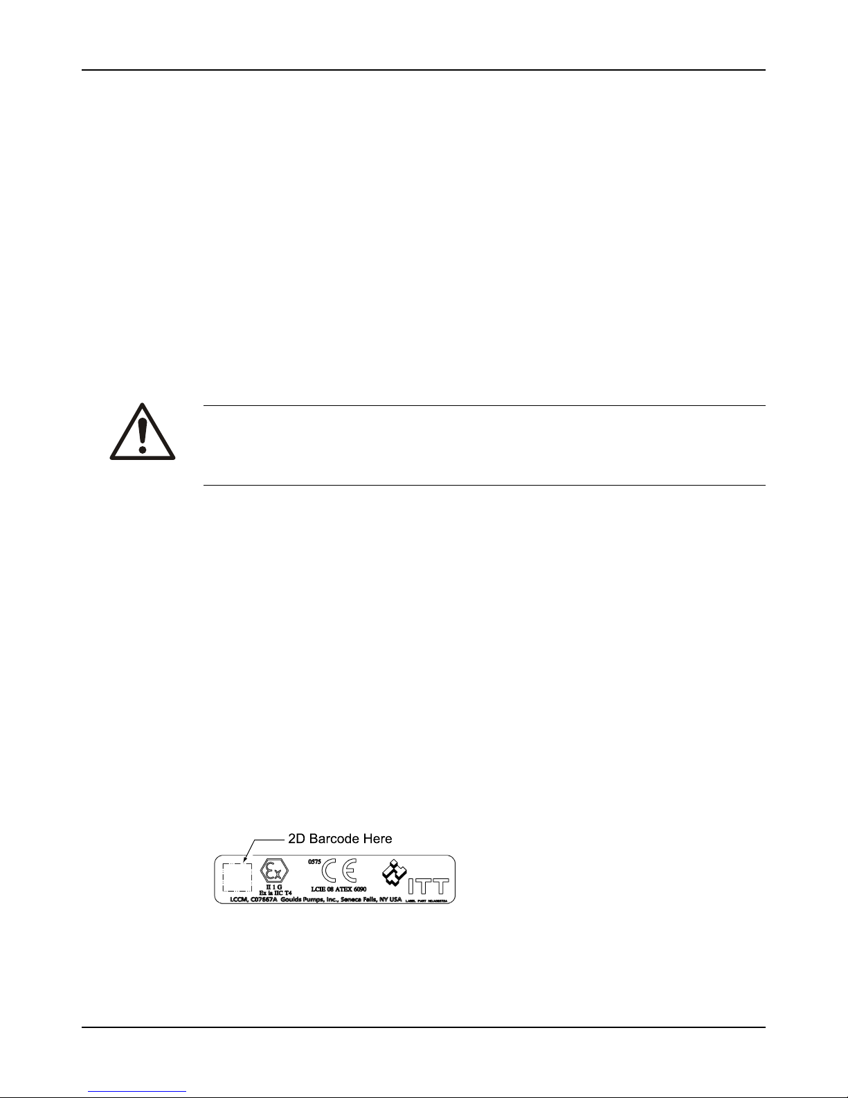
IECEx If applicable, your pump unit might have the following IECEx nameplate affixed to the pump and/or
baseplate. The nameplate provides information about the IECEx specifications of this pump.
Nameplate on the pump casing using English units
Figure 9: Nameplate on the pump casing using English units
Table 5: Explanation of nameplate on the pump casing
Nameplate field Explanation
IMPLR. DIA. Impeller diameter, in inches
MAX. DIA. Maximum impeller diameter, in inches
GPM Ratedpumpflow,ingallonsperminute
FT HD Rated pump head, in feet
RPM Rated pump speed, revolutions per minute
MOD. Pump model
SIZE Size of the pump
STD. NO. ANSIstandarddesignation
MAT L. CONST. Material of which the pump is constructed
SER. NO. Serial number of the pump
MAX DSGN PSI @
100ºF
Maximum pressure at 100ºF according to the pump design
Product Description
Model 3196 i-FRAME Installation, Operation, and Maintenance Manual 21
Nameplate on the pump casing using metric units
Figure 10: Metric units - nameplate on pump casing
Table 6: Explanation of the nameplate on the pump casing
Nameplate field Explanation
IMPLR. DIA. Impellerdiameter
MAX. DIA. Maximum impeller diameter
M3/HR Rated pump flow, in cubic meters per hour
M HD Rated pump head, in meters
RPM Rated pump speed, in revolutions per minute
MOD. Pump model
SIZE Size of the pump
STD. NO. ANSI standard designation
MAT L. CONST Material of which the pump is constructed
SER. NO. Serialnumberofthepump
MAX. DSGN KG/CM3@ 20°C Kilograms per cubic centimeter at 20°C
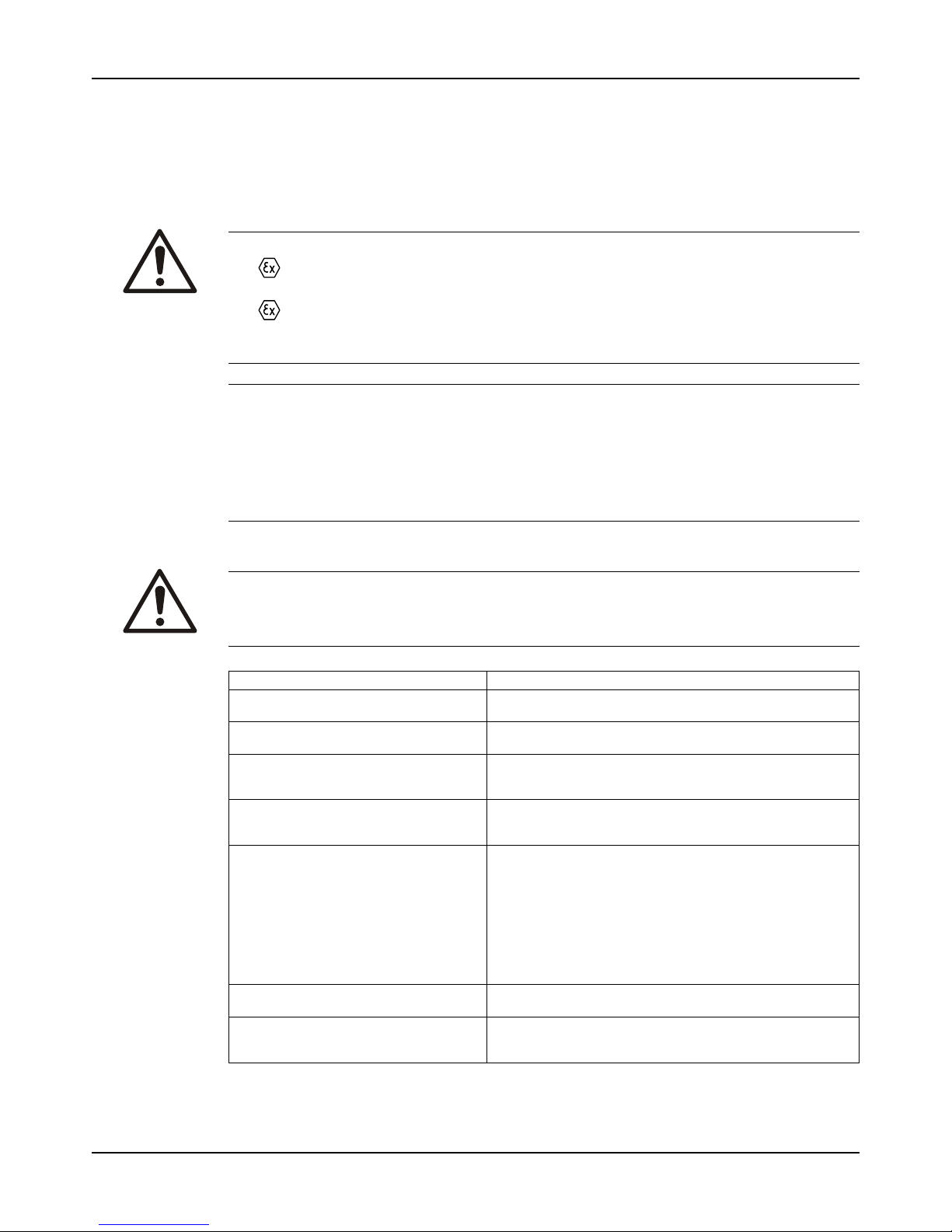
Nameplate on the bearing frame
Figure 11: Nameplate on the bearing frame
Table 7: Explanation of the nameplate on the bearing frame
Nameplate field Explanation
BRG. O. B. Outboard bearing designation
BRG. I. B. Inboard bearing designation
S/N Serial number of the pump
LUBE Lubricant, oil or grease
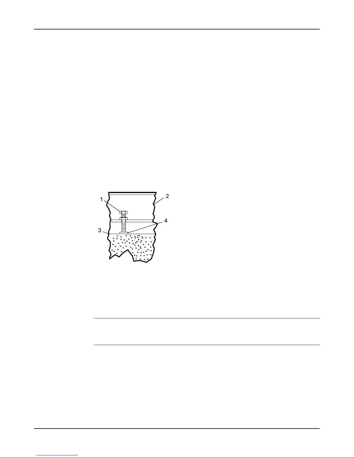
ATEX nameplate
Figure 12: ATEX nameplate
Nameplate field Explanation
II Group 2
2 Category 2

Product Description
Model 3196 i-FRAME Installation, Operation, and Maintenance Manual22
Nameplate field Explanation
G/D Pumpcanbeusedwhengasanddustarepresent
T4 Temperature class
WARNING:
Use of equipment unsuitable for the environment can pose risks of ignition and/or explosion.
Ensure that the code classifications on the pump are compatible with the specific environment
in which the equipment is to be installed. If they are not compatible, do not operate the
equipment and contact an ITT representative before proceeding.
Installation
Model 3196 i-FRAME Installation, Operation, and Maintenance Manual 23
Installation
Preinstallation
Precautions
WARNING:
• When installing in a potentially explosive environment, ensure that the motor is
properly certified.
• All equipment being installed must be properly grounded to prevent unexpected
discharge. Discharge can cause equipment damage, electric shock, and result in serious
injury. Test the ground lead to verify it is connected correctly.
NOTICE:
• Electrical connections must be made by certified electricians in compliance with all
international, national, state and local regulations.
• Supervision by an authorized ITT representative is recommended to ensure proper
installation. Improper installation may result in equipment damage or decreased performance.
Pump location guidelines
WARNING:
Safe lifting points are specifically identified in this manual. It is critical to lift the equipment only
at these points. Integral lifting eyes or eye bolts on pump and motor components are intended
for use in lifting the individual components only.
Guideline Explanation/comment
Keep the pump as close to the liquid
source as practically possible.
This minimizes the friction loss and keeps the suction piping
as short as possible.
Make sure that the space around the
pump is sufficient.
This facilitates ventilation, inspection, maintenance, and service.
If you require lifting equipment such as a
hoist or tackle, make sure that there is
enough space above the pump.
This makes it easier to properly use the lifting equipment and
safely remove and relocate the components to a safe
location.
Protect the unit from weather and water
damage due to rain, flooding, and freezing
temperatures.
This is applicable if nothing else is specified.
Do not install and operate the equipment
in closed systems unless the system is
constructed with properly-sized safety devices and control devices.
Acceptable devices:
• Pressure relief valves
• Compression tanks
• Pressure controls
• Temperature controls
• Flow controls
If the system does not include these devices, consult the
engineer or architect in charge before you operate the pump.
Take into consideration the occurrence of
unwanted noise and vibration.
The best pump location for noise and vibration absorption is
on a concrete floor with subsoil underneath.
If the pump location is overhead, undertake special precautions to reduce possible noise transmission.
Consider a consultation with a noise specialist.

Installation
Model 3196 i-FRAME Installation, Operation, and Maintenance Manual24
Foundation requirements
Requirements
• The foundation must be able to absorb any type of vibration and form a permanent, rigid
support for the unit.
• The location and size of the foundation bolt holes must match those shown on the
assembly drawing provided with the pump data package.
• The foundation must weigh between two and three times the weight of the pump.
• Provide a flat, substantial concrete foundation in order to prevent strain and distortion
when you tighten the foundation bolts.
Sleeve-type bolts
1. Baseplate
2. Shims or wedges
3. Foundation
4. Sleeve
5. Dam
6. Bolt
Figure 13: Sleeve type bolts
J-type bolts
1. Baseplate
2. Shims or wedges
3. Foundation
4. Dam
5. Bolt
Figure 14: J-type bolts
Baseplate-mounting procedures
Prepare the baseplate for mounting
1. Remove all the attached equipment from the baseplate.
2. Clean the underside of the baseplate completely.
3. If applicable, coat the underside of the baseplate with an epoxy primer.

Installation
Model 3196 i-FRAME Installation, Operation, and Maintenance Manual 25
Use an epoxy primer only if you used an epoxy-based grout.
4. Remove the rust-proofing coat from the machined mounting pads using an appropriate
solvent.
5. Remove water and debris from the foundation-bolt holes.
Install the baseplate using shims or wedges
Required tools:
• Two sets of shims or wedges for each foundation bolt
• Two machinist's levels
• Baseplate-leveling worksheet
This procedure is applicable to cast iron and fabricated steel baseplates.
1. If you use sleeve-type bolts, fill the bolt sleeves with packing material or rags to prevent
grout from entering the bolt holes.
2. Put the sets of wedges or shims on each side of each foundation bolt.
The sets of wedges should have a height of between 19 mm | 0.75 in. and 38 mm | 1.50 in.
1. Shims or wedges
Figure 15: Top view
1. Shims or wedges
Figure 16: Side view
3. Lower the baseplate carefully onto the foundation bolts.
4. Put the machinist's levels across the mounting pads of the driver and the mounting pads of
the pump.
NOTICE:
Remove all dirt from the mounting pads in order to ensure that the correct leveling is
achieved. Failure to do so can result in equipment damage or decreased performance.
5. Level the baseplate both lengthwise and across by adding or removing shims or moving the
wedges.
These are the leveling tolerances:
• A maximum difference of 3.2 mm | 0.125 in. lengthwise
• A maximum difference of 1.5 mm | 0.059 in. across
You can use the baseplate-leveling worksheet when you take the readings.
6. Hand-tighten the nuts for the foundation.
Installation
Model 3196 i-FRAME Installation, Operation, and Maintenance Manual26
Install the baseplate using jackscrews
Tools required:
• Anti-seize compound
• Jackscrews
• Bar stock
• Two machinist's levels
• Baseplate-leveling worksheet
This procedure is applicable to the feature-fabricated steel baseplate and the advantage base
baseplate.
1. Apply an anti-seize compound on the jackscrews.
The compound makes it easier to remove the screws after you grout.
2. Lower the baseplate carefully onto the foundation bolts and perform these steps:
a) Cut the plates from the bar stock and chamfer the edges of the plates in order to reduce
stress concentrations.
b) Put the plates between the jackscrews and the foundation surface.
c) Use the four jackscrews in the corners in order to raise the baseplate above the
foundation.
Make sure that the distance between the baseplate and the foundation surface is
between 19 mm | 0.75 in. and 38 mm | 1.50 in.
d) Make sure that the center jackscrews do not touch the foundation surface yet.
1. Jackscrew
2. Baseplate
3. Foundation
4. Plate
Figure 17: Jackscrews
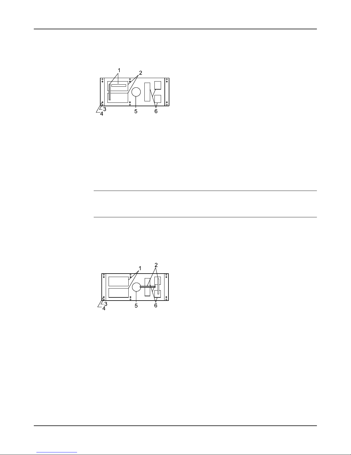
3. Level the driver mounting pads:
NOTICE:
Remove all dirt from the mounting pads in order to ensure that the correct leveling is
achieved. Failure to do so can result in equipment damage or decreased performance.
a) Put one machinist's level lengthwise on one of the two pads.
b) Put the other machinist's level across the ends of the two pads.
Installation
Model 3196 i-FRAME Installation, Operation, and Maintenance Manual 27
c) Level the pads by adjusting the four jackscrews in the corners.
Make sure that the machinist's level readings are as close to zero as possible, both
lengthwise and across.
Use the baseplate-leveling worksheet when you take the readings.
1. Machinist's levels
2. Driver's mounting pads
3. Foundation bolts
4. Jackscrews
5. Grout hole
6. Pump's mounting pads
Figure 18: Level driver mounting pads
4. Turn the center jackscrews down so that they rest on their plates on the foundation surface.
5. Level the pump mounting pads:
NOTICE:
Remove all dirt from the mounting pads in order to ensure that the correct leveling is
achieved. Failure to do so can result in equipment damage or decreased performance.
a) Put one machinist's level lengthwise on one of the two pads.
b) Put the other level across the center of the two pads.
c) Level the pads by adjusting the four jackscrews in the corners.
Make sure that the machinist's level readings are as close to zero as possible, both
lengthwise and across.
1. Driver's mounting pads
2. Machinist's levels
3. Foundation bolts
4. Jackscrews
5. Grout hole
6. Pump's mounting pads
Figure 19: Level pump mounting pads
6. Hand-tighten the nuts for the foundation bolts.
7. Check that the driver's mounting pads are level and adjust the jackscrews and the
foundation bolts if necessary.
The correct level measurement is a maximum of 0.0167 mm/m | 0.002 in./ft .

Installation
Model 3196 i-FRAME Installation, Operation, and Maintenance Manual28
Install the baseplate using spring mounting
NOTICE:
The spring-mounted baseplate is designed only to support piping loads from thermal
expansion. Ensure that the suction and discharge piping are supported individually. Failure to
do so may result in equipment damage.
The foundation pads are not provided with the baseplate. Make sure that the foundation pads
are 316 stainless-steel plates, which have a 16-20 micro-inch surface finish.
Before you start this procedure, make sure that the foundation pads are correctly installed on
the foundation/floor (see the manufacturer's instructions).
1. Put the baseplate on a support above the foundation/floor.
Make sure that there is enough space between the baseplate and the foundation/floor in
order to install the spring assemblies.
2. Install the lower part of the spring assembly:
a) Screw the lower jam nut onto the spring stud.
b) Screw the lower adjusting nut onto the spring-stud, on top of the jam nut.
c) Set the lower adjusting nut to the correct height.
The correct height depends on the required distance between the foundation/floor and
the baseplate.
d) Put a washer, a follower, a spring, and one more follower onto the lower adjusting nut.
3. Install the spring assembly on the baseplate:
a) Insert the spring assembly into the baseplate's anchorage hole from below.
b) Put a follower, a spring, another follower, and a washer onto the spring stud.
c) Fasten the spring assembly with the upper adjusting nut by hand.
4. Thread the upper jam nut onto the spring stud by hand.
5. Repeat steps 2 through 4 for all the spring assemblies.
6. Lower the baseplate so that the spring assemblies fit into the foundation pads.
7. Level the baseplate and make the final height adjustments:
a) Loosen the upper jam nuts and adjusting nuts.
b) Adjust the height and level the baseplate by moving the lower adjusting nuts.
c) When the baseplate is level, tighten the top adjusting nuts so that the top springs are
not loose in their followers.
8. Fasten the lower and upper jam nuts on each spring assembly.
 Loading...