

Goulds Pumps 2GFK3813A, 2GFV3814J, 2GFV3812J, 2GFK3814A, 2GFK3815A Installation, Operation And Maintenance Manual
...
Installation, Operation, and
Maintenance Manual
887072_3.0
GFK-GFV Series
Submersible Sewage Pumps


Pump models included in the IOM
2GFK3812A 2GFV3812J
2GFK3813A 2GFV3813J
2GFK3814A 2GFV3814J
2GFK3815A 2GFV3815J
2GFK3212G 2GFV3212K
2GFK3213G 2GFV3213K
2GFK3214G 2GFV3214K
2GFK3215G 2GFV3215K
2GFK2412H
2GFK2413H
2GFK2414H
2GFK2415H
Pump models included in the IOM
GFK-GFV Series Installation, Operation, and Maintenance Manual

Table of Contents
1 Introduction and Safety............................................................................................................................................................. 2
1.1 Introduction.................................................................................................................................................................................. 2
1.2 Safety terminology and symbols................................................................................................................................................2
1.3 User safety.....................................................................................................................................................................................2
1.4 Ex-approved products................................................................................................................................................................ 2
1.5 Special hazards............................................................................................................................................................................ 3
1.6 Protecting the environment........................................................................................................................................................3
1.7 Spare parts....................................................................................................................................................................................3
1.8 Warranty........................................................................................................................................................................................3
2 Transportation and Storage.......................................................................................................................................................3
2.1 Examine the delivery................................................................................................................................................................... 3
2.1.1 Examine the package.......................................................................................................................................................... 3
2.1.2 Examine the unit.................................................................................................................................................................. 3
2.2 Transportation guidelines...........................................................................................................................................................3
2.2.1 Lifting.....................................................................................................................................................................................4
2.3 Temperature ranges for transportation, handling and storage.............................................................................................4
2.4 Storage guidelines.......................................................................................................................................................................4
3 Product Description...................................................................................................................................................................4
3.1 Products included........................................................................................................................................................................4
3.2 Pump design................................................................................................................................................................................ 4
3.3 Monitoring Equipment................................................................................................................................................................5
3.4 The data plate.............................................................................................................................................................................. 5
3.5 Product denomination................................................................................................................................................................ 5
4 Installation................................................................................................................................................................................. 6
4.1 Install the pump........................................................................................................................................................................... 6
4.1.1 Install with Wet well installation......................................................................................................................................... 6
4.1.2 Install with Free-standing installation................................................................................................................................7
4.2 Make the electrical connections................................................................................................................................................ 7
4.2.1 Connect the motor cable to the pump............................................................................................................................. 8
4.2.2 Connect the motor cable to the starter and monitoring equipment............................................................................ 8
4.2.3 Cable charts..........................................................................................................................................................................9
4.3 Check the impeller rotation......................................................................................................................................................11
5 Operation.................................................................................................................................................................................11
5.1 Precautions.................................................................................................................................................................................11
5.2 Start the pump........................................................................................................................................................................... 11
6 Maintenance............................................................................................................................................................................11
6.1 Change the coolant...................................................................................................................................................................12
6.1.1 Empty the coolant..............................................................................................................................................................12
6.1.2 Fill with coolant.................................................................................................................................................................. 12
6.2 Service the pump.......................................................................................................................................................................13
6.2.1 Inspection........................................................................................................................................................................... 13
6.2.2 Overhaul............................................................................................................................................................................. 13
6.2.3 Service in case of alarm.................................................................................................................................................... 13
6.3 Replace the impeller................................................................................................................................................................. 14
6.3.1 Remove the impeller: Non-clog and Vortex (H, M) ...................................................................................................... 14
6.3.2 Remove the impeller: Vortex (L)...................................................................................................................................... 14
6.3.3 Install the impeller............................................................................................................................................................. 14
7 Troubleshooting.......................................................................................................................................................................15
7.1 The pump does not start.......................................................................................................................................................... 16
7.2 The pump does not stop when a level sensor is used..........................................................................................................16
7.3 The pump starts-stops-starts in rapid sequence................................................................................................................... 16
7.4 The pump runs but the motor protection trips......................................................................................................................17
7.5 The pump delivers too little or no water................................................................................................................................ 17
8 Technical Reference................................................................................................................................................................17
8.1 Motor data.................................................................................................................................................................................. 17
Table of Contents
GFK-GFV Series Installation, Operation, and Maintenance Manual 1
1 Introduction and Safety
1 Introduction and Safety
1.1 Introduction
Electrical hazard Magnetic fields hazard
Electrical Hazard:
CAUTION:
Purpose of the manual
The purpose of this manual is to provide necessary information for
working with the unit. Read this manual carefully before starting work.
Read and keep the manual
Save this manual for future reference, and keep it readily available at
the location of the unit.
Intended use
WARNING:
Operating, installing, or maintaining the unit in any way that
is not covered in this manual could cause death, serious personal injury, or damage to the equipment and the surroundings. This includes any modification to the equipment or use
of parts not provided by Xylem. If there is a question regarding the intended use of the equipment, please contact a Xylem representative before proceeding.
Other manuals
See also the safety requirements and information in the original manufacturer's manuals for any other equipment furnished separately for use
in this system.
Description of user and installer symbols
Specific information for personnel in charge of installing
the product in the system (plumbing and/or electrical
aspects) or in charge of maintenance.
Specific information for users of the product.
1.2 Safety terminology and symbols
About safety messages
It is extremely important that you read, understand, and follow the safety messages and regulations carefully before handling the product.
They are published to help prevent these hazards:
• Personal accidents and health problems
• Damage to the product and its surroundings
• Product malfunction
Hazard levels
Hazard level Indication
DANGER:
WARNING:
CAUTION:
NOTICE:
Special symbols
Some hazard categories have specific symbols, as shown in the following table.
A hazardous situation which, if not
avoided, will result in death or serious injury
A hazardous situation which, if not
avoided, could result in death or
serious injury
A hazardous situation which, if not
avoided, could result in minor or
moderate injury
Notices are used when there is a
risk of equipment damage or decreased performance, but not personal injury.
1.3 User safety
All regulations, codes, and health and safety directives must be observed.
The site
• Observe lockout/tagout procedures before starting work on the
product, such as transportation, installation, maintenance, or service.
• Pay attention to the risks presented by gas and vapors in the work
area.
• Always be aware of the area surrounding the equipment, and any
hazards posed by the site or nearby equipment.
Qualified personnel
This product must be installed, operated, and maintained by qualified
personnel only.
Protective equipment and safety devices
• Use personal protective equipment as needed. Examples of personal protective equipment include, but are not limited to, hard hats,
safety goggles, protective gloves and shoes, and breathing equipment.
• Make sure that all safety features on the product are functioning
and in use at all times when the unit is being operated.
1.4 Ex-approved products
Follow these special handling instructions if you have an Ex-approved
unit.
Personnel requirements
These are the personnel requirements for Ex-approved products in potentially explosive atmospheres:
• All work on the product must be carried out by certified electricians
and Xylem authorized mechanics. Special rules apply to installations
in explosive atmospheres.
• All users must know about the risks of electric current and the
chemical and physical characteristics of the gas, the vapor, or both
present in hazardous areas.
• Any maintenance for Ex-approved products must conform to international and national standards (for example, IEC/EN 60079-17).
Xylem disclaims all responsibility for work done by untrained and unauthorized personnel.
Product and product handling requirements
These are the product and product handling requirements for Ex-approved products in potentially explosive atmospheres:
• Only use the product in accordance with the approved motor data.
• You must fully submerge the Ex-approved product during normal
operation. Dry running during service and inspection is only permitted outside the classified area.
• Before you start work on the product, make sure that the product
and the control panel are isolated from the power supply and the
control circuit, so they cannot be energized.
• Do not open the product while it is energized or in an explosive gas
atmosphere.
• Intrinsically safe circuits are normally required for the automatic level-control system by the level regulator if mounted in zone 0.
• The yield stress of fasteners must be in accordance with the approval drawing and the product specification.
• Do not modify the equipment without approval from an Ex-approved Xylem representative.
• Only use original Xylem spare parts that are provided by an Ex-approved Xylem representative.
• The thermal detectors that are fitted to the stator windings must be
connected correctly to a separate motor control circuit and in use.
The detectors disconnect the power supply to the motor timely.
This action prevents the rise of temperatures above the temperature value for the approval classification.
2 GFK-GFV Series Installation, Operation, and Maintenance Manual
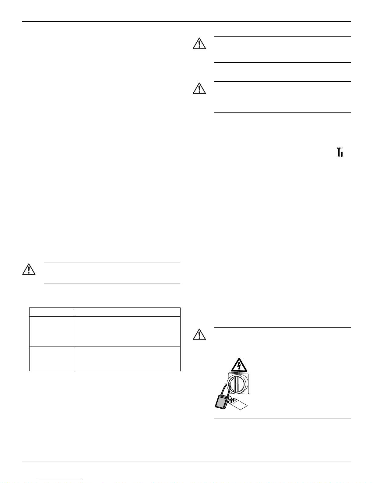
Equipment
locked out by
Name .......................
DANGER
2 Transportation and Storage
• The width of flameproof joints is more than the values specified in
the tables of the IEC 60079–1 standard.
• The gap of flameproof joints is less than the values specified in Table 1 of the IEC 60079–1 standard.
• The flameproof joints are NOT intended to be repaired.
• The equipment must be submerged during normal operation.
Guidelines for compliance
Compliance is fulfilled only when you operate the unit within its intended use. Do not change the conditions of the service without the approval of an Ex-approved Xylem representative. When you install or maintain explosion proof products, always comply with the directive and applicable standards (for example, IEC/EN 60079–14).
Minimum permitted liquid level
See the dimensional drawings of the product for the minimum permitted liquid level according to the approval for explosion proof products.
If the information is missing on the dimensional drawing, the product
must be fully submerged. Level-sensing equipment must be installed if
the product can be operated at less than the minimum submersion
depth.
Monitoring equipment
For additional safety, use condition-monitoring devices. Examples of
condition-monitoring devices include, but are not limited to, the following:
• Level indicators
• Temperature detectors in addition to the stator thermal detectors
Any thermal detectors or thermal protection devices delivered with the
pump must be installed and in use at all times.
1.5 Special hazards
Biological hazards
The product is designed for use in liquids that can be hazardous to
your health. Observe these rules when you work with the product:
• Make sure that all personnel who may come into contact with biological hazards are vaccinated against diseases to which they may
be exposed.
• Observe strict personal cleanliness.
WARNING: Biological Hazard
Infection risk. Rinse the unit thoroughly with clean water before working on it.
Wash the skin and eyes
Follow these procedures for chemicals or hazardous fluids that have
come into contact with your eyes or your skin:
Condition Action
Chemicals or hazardous fluids in
eyes
Chemicals or hazardous fluids on
skin
1. Hold your eyelids apart forcibly with your
fingers.
2. Rinse the eyes with eyewash or running
water for at least 15 minutes.
3. Seek medical attention.
1. Remove contaminated clothing.
2. Wash the skin with soap and water for at
least 1 minute.
3. Seek medical attention, if necessary.
Exceptional sites
CAUTION: Radiation Hazard
Do NOT send the product to Xylem if it has been exposed to
nuclear radiation, unless Xylem has been informed and appropriate actions have been agreed upon.
1.7 Spare parts
CAUTION:
Only use the manufacturer’s original spare parts to replace
any worn or faulty components. The use of unsuitable spare
parts may cause malfunctions, damage, and injuries as well
as void the warranty.
1.8 Warranty
For information about warranty, see the sales contract.
2 Transportation and Storage
2.1 Examine the delivery
2.1.1 Examine the package
1. Examine the package for damaged or missing items upon delivery.
2. Record any damaged or missing items on the receipt and freight
bill.
3. If anything is out of order, then file a claim with the shipping company.
If the product has been picked up at a distributor, make a claim directly to the distributor.
2.1.2 Examine the unit
1. Remove packing materials from the product.
Dispose of all packing materials in accordance with local regula-
tions.
2. To determine whether any parts have been damaged or are missing, examine the product.
3. If applicable, unfasten the product by removing any screws, bolts,
or straps.
Use care around nails and straps.
4. If there is any issue, then contact a sales representative.
2.2 Transportation guidelines
Precautions
DANGER: Crush Hazard
Moving parts can entangle or crush. Always disconnect and
lock out power before servicing to prevent unexpected startup. Failure to do so could result in death or serious injury.
1.6 Protecting the environment
Emissions and waste disposal
Observe the local regulations and codes regarding:
• Reporting of emissions to the appropriate authorities
• Sorting, recycling and disposal of solid or liquid waste
• Clean-up of spills
GFK-GFV Series Installation, Operation, and Maintenance Manual 3
Position and fastening
The unit can be transported either horizontally or vertically. Make sure
that the unit is correctly fastened during transportation, and cannot roll
or fall over.
3 Product Description
2.2.1 Lifting
Always inspect the lifting equipment and tackle before starting any
work.
WARNING: Crush Hazard
1) Always lift the unit by its designated lifting points. 2) Use
suitable lifting equipment and ensure that the product is
properly harnessed. 3) Wear personal protective equipment.
4) Stay clear of cables and suspended loads.
NOTICE:
Never lift the unit by its cables or hose.
Lifting equipment
Lifting equipment is always required to handle the unit. The lifting
equipment must fulfill the following requirements:
• The minimum height between the lifting hook and the floor must be
sufficient to lift the unit. Contact a Xylem representative for more information.
• The lifting equipment must be able to hoist the unit straight up and
down, preferably without the need for resetting the lifting hook.
• The lifting equipment must be correctly anchored and in good condition.
• The lifting equipment must support the weight of the entire assembly. Only authorized personnel may use the lifting equipment.
• Two sets of lifting equipment must be used to lift the unit for repair
work.
• The lifting equipment must be dimensioned to lift the unit with any
remaining pumped media in it.
• The lifting equipment must not be oversized.
CAUTION: Crush Hazard
Over-dimensioned lifting equipment can lead to injury. A
site-specific risk analysis must be done.
Below –13°C (9°F), the viscosity increases such that the glycol mixture
will lose its flow properties. However, the glycol-water mixture will not
solidify completely and thus cannot harm the product.
2.4 Storage guidelines
Storage location
The product must be stored in a covered and dry location free from
heat, dirt, and vibrations.
NOTICE:
Protect the product against humidity, heat sources, and mechanical
damage.
NOTICE:
Do not place heavy weights on the packed product.
Long-term storage
If the unit is stored more than six months, then the following apply:
• Before operating the unit after storage, it must be inspected with
special attention to the seals and the cable entry.
• The impeller/propeller must be rotated every other month to prevent the seals from sticking together.
3 Product Description
3.1 Products included
Pump model Standard EX
1310.181 X
2.3 Temperature ranges for transportation,
handling and storage
Handling at freezing temperature
At temperatures below freezing, the product and all installation equipment, including the lifting gear, must be handled with extreme care.
Make sure that the product is warmed up to a temperature above the
freezing point before starting up. Avoid rotating the impeller/propeller
by hand at temperatures below the freezing point. The recommended
method to warm the unit up is to submerge it in the liquid which will be
pumped or mixed.
NOTICE:
Never use a naked flame to thaw the unit.
Unit in as-delivered condition
If the unit is still in the condition in which it left the factory - all packing
materials are undisturbed - then the acceptable temperature range
during transportation, handling and storage is: –50°C (–58ºF) to +60°C
(+140ºF).
If the unit has been exposed to freezing temperatures, then allow it to
reach the ambient temperature of the sump before operating.
Lifting the unit out of liquid
The unit is normally protected from freezing while operating or immersed in liquid, but the impeller/propeller and the shaft seal may
freeze if the unit is lifted out of the liquid into a surrounding temperature below freezing.
Follow these guidelines to avoid freezing damage:
1. Empty all pumped liquid, if applicable.
2. Check all liquids used for lubrication or cooling, both oil and waterglycol mixtures, for the presence of unacceptable amounts of water.
Change if needed.
Water-glycol mixtures: Units equipped with an internal closed-loop
cooling system are filled with a mixture of water and 30% glycol. This
mixture remains a flowing liquid at temperatures down to –13°C (9°F).
3.2 Pump design
The pump is submersible, and driven by an electric motor.
Intended use
The product is intended for moving wastewater, sludge, raw and clean
water. Always follow the application limits that are given in Technical
Reference on page 17. If there is a question regarding the intended
use of the equipment, please contact a local sales and service representative before proceeding.
DANGER: Explosion/Fire Hazard
Special rules apply to installations in explosive or flammable
atmospheres. Do not install the product or any auxiliary
equipment in an explosive zone unless it is rated explosionproof or intrinsically-safe. If the product is EN/ATEX-, MSHAor FM-approved, then see the specific EX information in the
Safety chapter before taking any further actions.
NOTICE:
Do NOT use the unit in highly corrosive liquids.
Spare parts
• Modifications to the unit or installation should only be carried out
after consulting with Xylem.
• Original spare parts and accessories that are authorized by Xylem
are essential for compliance. The use of other parts can invalidate
any claims for warranty or compensation. For more information contact your Xylem representative.
Model variants
L
M Medium head
H High head
S Super high head
Low head
4 GFK-GFV Series Installation, Operation, and Maintenance Manual
1
2
3
4
5
6
7
9
8
WS007964A
2
1312 14
22
21
20
17 18 1916159 10 11
8
7
6
5
4
3
1
23
24
WS006257A
3 Product Description
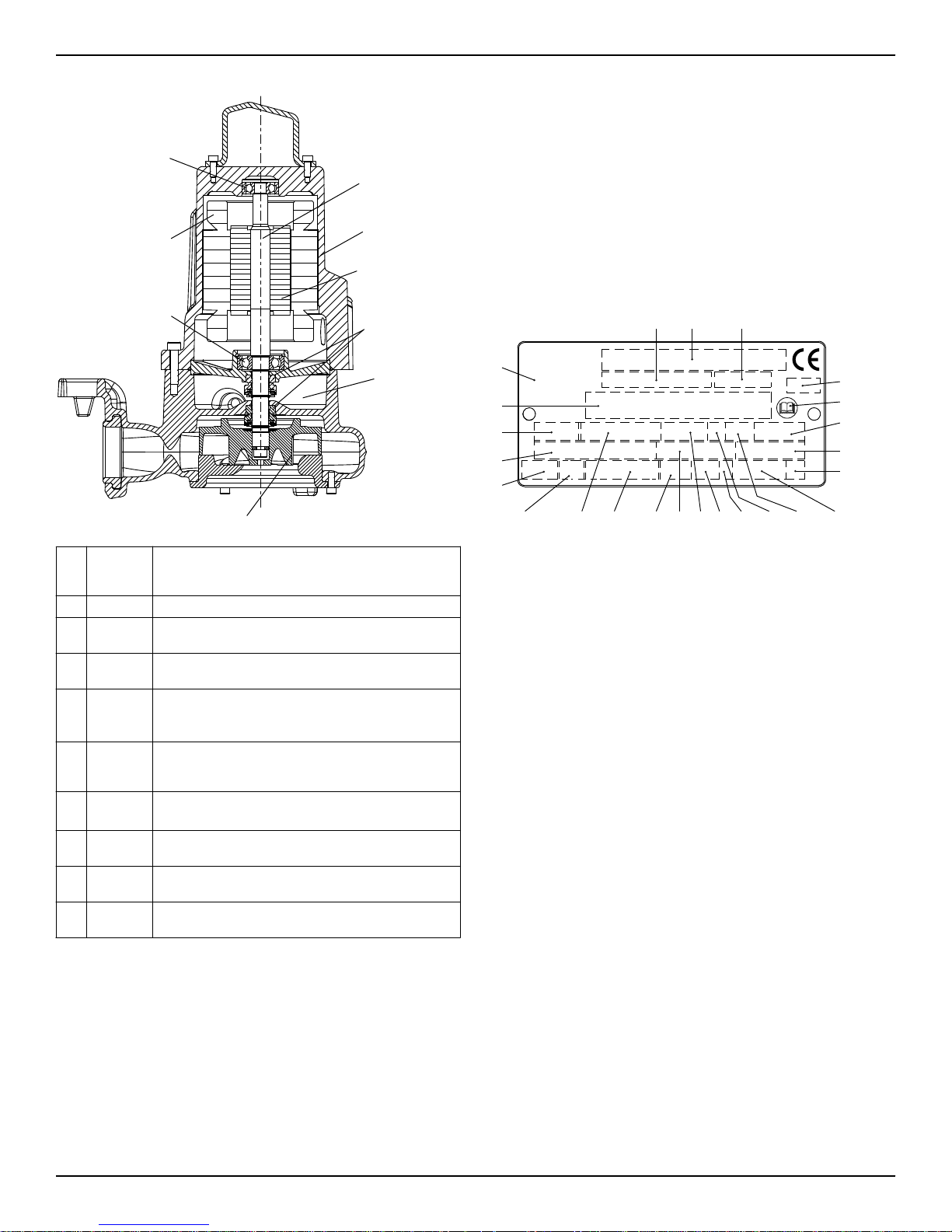
Parts
• The monitoring equipment must be of a design that makes automatic restart impossible.
• Information in the junction box shows if the pump is equipped with
optional sensors
Optional sensors
LD LD is a miniature float switch for detection of liquid in the stator
housing. Due to its design, it is best suited for pumps in a vertical
position. The LD sensor is installed in the bottom of the stator
housing.
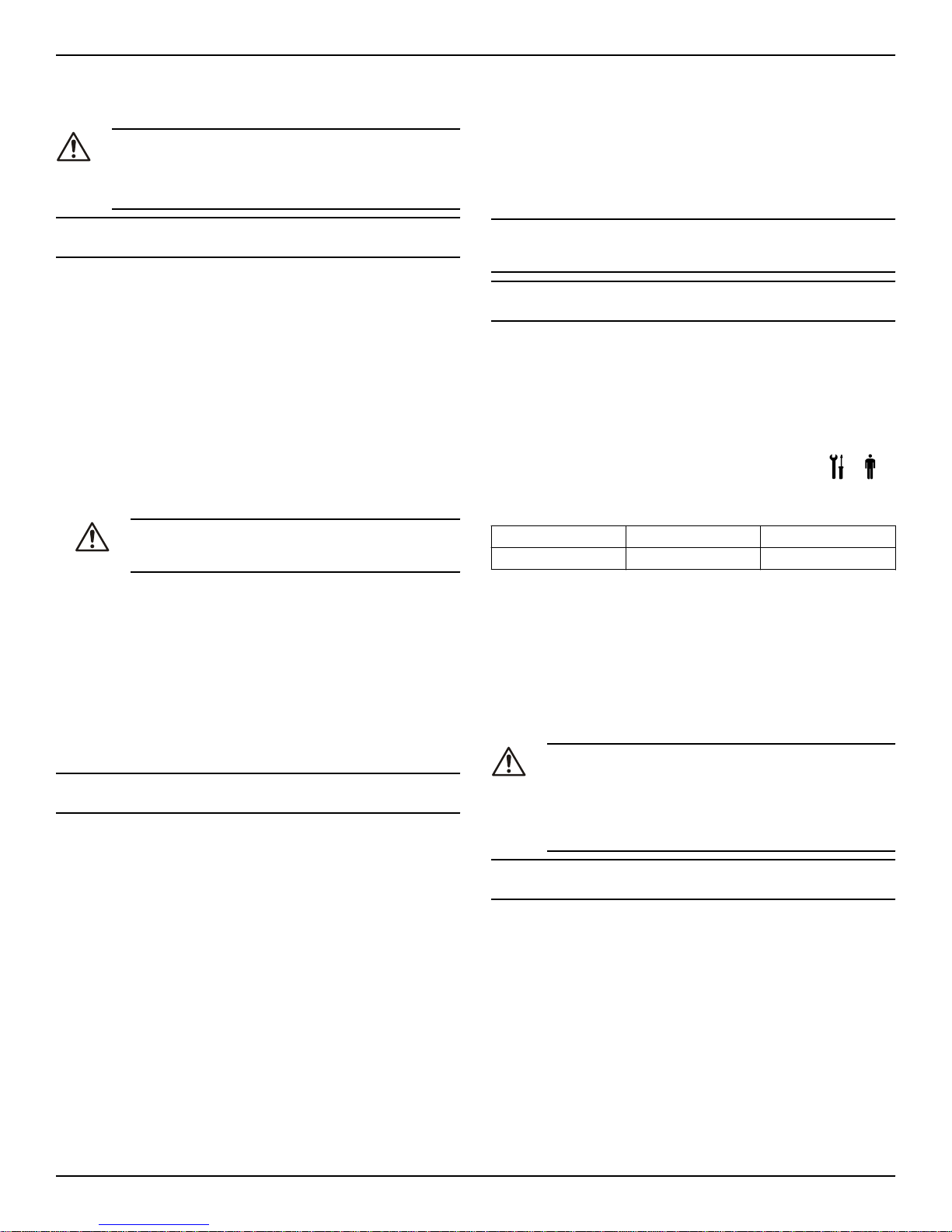
3.4 The data plate
The data plate is a metal label that is located on the main body of the
products. The data plate lists key product specifications. Specially approved products also have an approval plate.
Po-
Denomi-
si-
nation
tion
1 Shaft Stainless steel with an integrated rotor
2 Stator
housing
3 Motor For information about the motor, see Technical Reference
4 Mechani-
cal seal
5 Oil hous-
ing
6 Impeller Vortex
7 Main
bearing
8 Thermal
contact
9 Support
bearing
3.3 Monitoring Equipment
The following applies to the monitoring equipment of the pump:
GFK-GFV Series Installation, Operation, and Maintenance Manual 5
• The stator incorporates thermal contacts that are connected in series that activate the alarm at overtemperature.
• The thermal contacts open at 125°C (257°F).
• Ex-approved pumps must have thermal contacts that are connected
to the control panel.
• The sensors must be connected to either the SMR 311 monitoring
equipment or equivalent equipment.
Description
Cooled by ambient liquid
on page 17.
Inner seal: carbon/aluminium oxide CSB/Al2O
Outer seal: corrosion-resistant cemented carbide/
aluminium oxide WCCR/Al2O
Includes coolant that lubricates and cools the seals;
acts as a buffer between the pumped fluid and the
electric motor
Non-clog
Single-row ball bearing
The pump is equipped with thermal contacts, see
Monitoring Equipment on page 5 .
Single-row ball bearing
1. Curve code or Propeller code
2. Serial number
3. Product number
4. Country of origin
5. Additional information
6. Phase; type of current; frequency
7. Rated voltage
8. Thermal protection
9. Thermal class
10.Rated shaft power
11.International standard
12.Degree of protection
13.Rated current
3
3
14.Rated speed
15.Maximum submergence
16.Direction of rotation: L=left, R=right
17.Duty class
18.Duty factor
19.Product weight
20.Locked rotor code letter
21.Power factor
22.Maximum ambient temperature
23.Read installation manual
24.Notified body, only for EN-approved Ex products
Figure 1: The data plate
3.5 Product denomination
Reading instruction
In this section, code characters are illustrated accordingly:
X = letter
Y = digit
The different types of codes are marked up with a, b and c. Code pa-
rameters are marked up with numbers.
 Loading...