

Goulds Pumps 231-INSIDER-P, 111-INSIDER-P Installation Manual
INSTALLATION
INSTRUCTIONS
Rapid City, SD, USA, 09/2009
MODEL 231/111-INSIDER-P
Revision C1
II_231-111-INS-P_C1
2880 North Plaza Drive, Rapid City, South Dakota 57702
(800) 843-8848 · (605) 348-5580 · fax (605) 348-5685

BE SURE POWER IS DISCONNECTED PRIOR TO INSTALLATION!
FOLLOW NATIONAL, STATE AND LOCAL CODES.
The PumpSaver
CentriPro
Pentek
from dry-well, dead-head, rapid-cycling, jammed impeller, and over/undervoltage conditions. Typical
applications include residential water wells, commercial water wells, irrigation wells, and golf course
and other sprinkler systems.
CONNECTIONS
Refer to specific connection instructions depending on the particular control box being used:
Franklin
Pentek
CentriPro
After the PumpSaver
outside of the control box.
READ THESE INSTRUCTIONS ENTIRELY BEFORE INSTALLATION.
®
Plus Model 231-INSIDER-P fits inside 1/3 – 1hp, 230V Franklin™, Pentek®, or
™
control boxes. The Model 111-INSIDER-P fits inside 1/3 and 1/2hp, 115VAC Franklin™,
®
or CentriPro™ control boxes. PumpSavers are designed to protect single-phase pumps
™
control box – page 3
®
control box – page 5
™
control box – page 7
®
Plus has been installed, place the provided PumpSaver®Plus Label on the
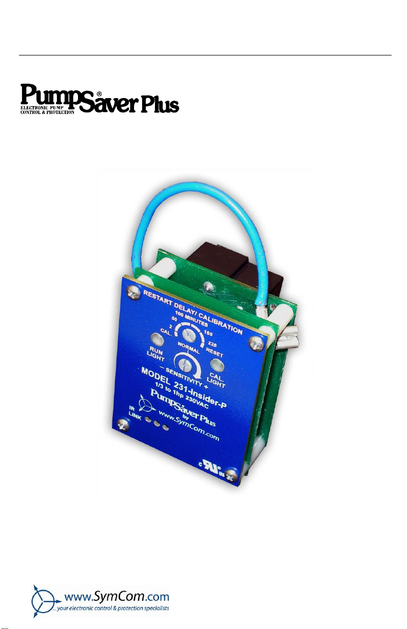
FIGURE 1: PumpSaver
®
Plus Enclosure Label
*** WARNING ***
PROPER OPERATION REQUIRES FIELD CALIBRATION
© 2009 SymCom, Inc. All Rights Reserved 2
FRANKLIN™ CONTROL BOX
CONNECTIONS
1. Remove the cover from the front of the 3-wire Franklin
2. Disconnect the yellow wire from terminal L2 and remove the blue wire completely from th e
control box (save the blue wire for future use).
3. Connect the blue wire attached to the PumpSaver
switch.
4. Press the PumpSaver
5. Reconnect the yellow wire to L2 on the PumpSaver
®
Plus onto the L1 and L2 terminals.
™
control box.
®
Plus to the L1 terminal on the solid-state
®
Plus.
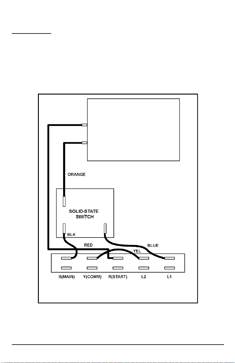
FIGURE 2: Franklin™ Control Box without the PumpSaver®Plus
© 2009 SymCom, Inc. All Rights Reserved 3
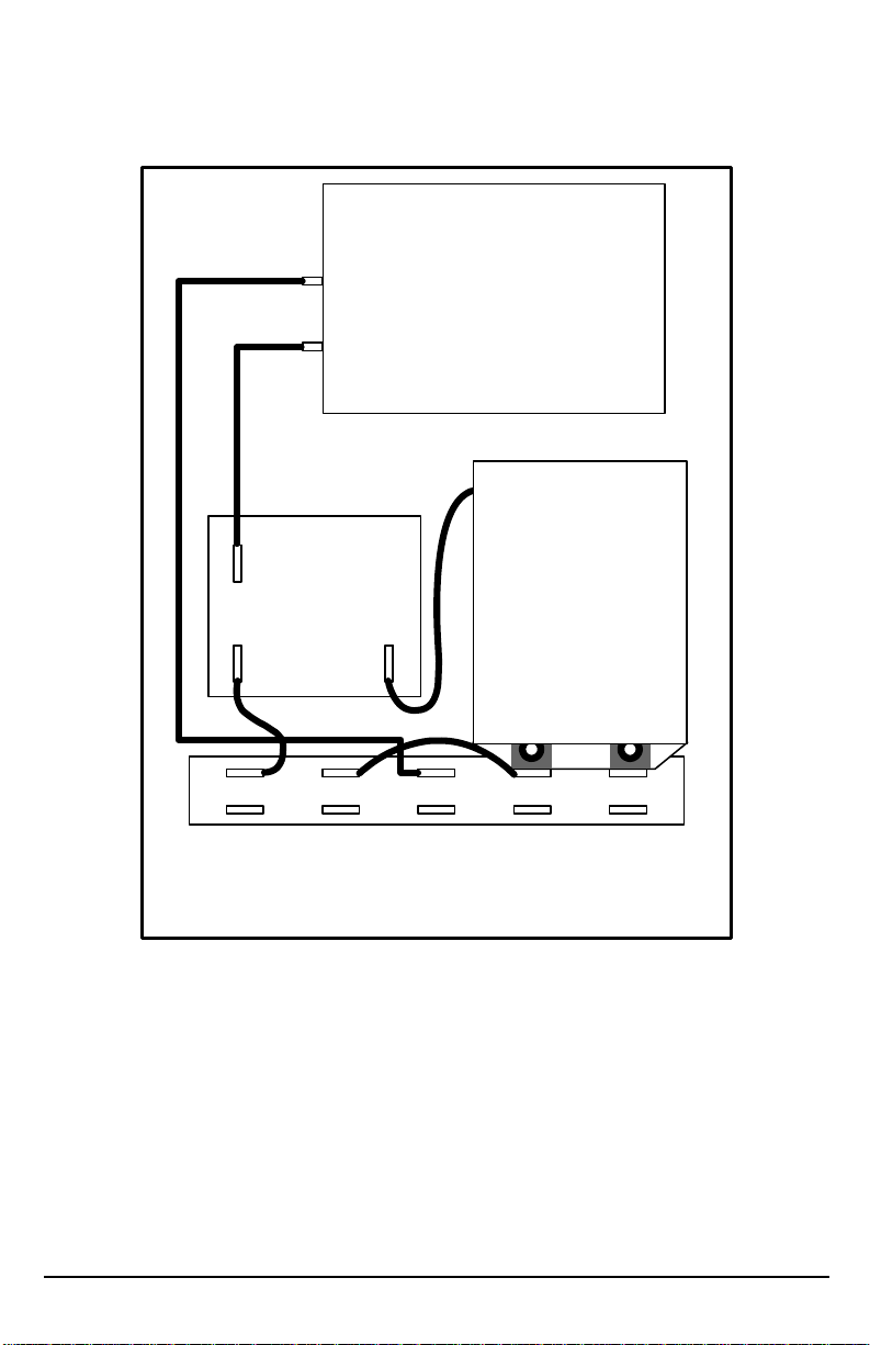
FRANKLIN™ CONTROL BOX
ORANGE
BLUE
SOLID-STATE
SWITCH
BLK
231/111
INSIDER-P
RED
B(MAIN) Y(COMM)
YEL
R(START) L2 L1
FIGURE 3: Franklin™ Control Box with the PumpSaver®Plus Installed
© 2009 SymCom, Inc. All Rights Reserved 4
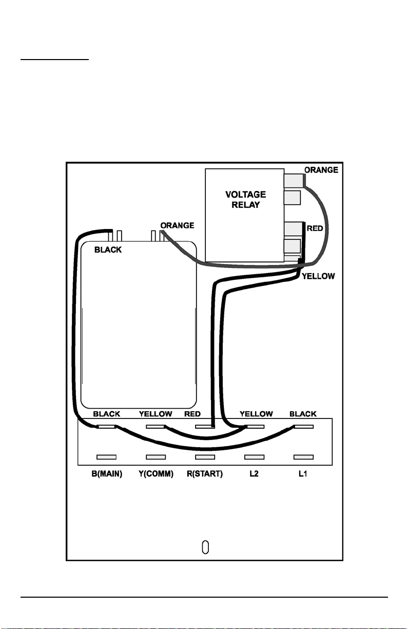
PENTEK® CONTROL BOX
CONNECTIONS
1. Remove the cover from the front of the 3-wire Pentek® control box.
2. Disconnect the yellow wire from terminal L2.
3. Cut and remove the black wire connecting L1 and B (MAIN).
4. Press the PumpSaver
5. Reconnect the yellow wire to L2 on the PumpSaver
6. Connect the blue wire attached to the PumpSaver®Plus to the dual-lug terminal with the black
wire at the top of the capacitor.
®
Plus onto the L1 and L2 terminals.
®
Plus.
FIGURE 4: Pentek® Control Box without the PumpSaver®Plus Installed
© 2009 SymCom, Inc. All Rights Reserved 5
 Loading...